EP4031867B1 - Vorrichtung zur entnahme einer probe einer biologischen flüssigkeit - Google Patents
Vorrichtung zur entnahme einer probe einer biologischen flüssigkeit Download PDFInfo
- Publication number
- EP4031867B1 EP4031867B1 EP20771859.4A EP20771859A EP4031867B1 EP 4031867 B1 EP4031867 B1 EP 4031867B1 EP 20771859 A EP20771859 A EP 20771859A EP 4031867 B1 EP4031867 B1 EP 4031867B1
- Authority
- EP
- European Patent Office
- Prior art keywords
- housing
- strip
- diffusion
- band
- absorbent
- Prior art date
- Legal status (The legal status is an assumption and is not a legal conclusion. Google has not performed a legal analysis and makes no representation as to the accuracy of the status listed.)
- Active
Links
Images





Classifications
-
- B—PERFORMING OPERATIONS; TRANSPORTING
- B01—PHYSICAL OR CHEMICAL PROCESSES OR APPARATUS IN GENERAL
- B01L—CHEMICAL OR PHYSICAL LABORATORY APPARATUS FOR GENERAL USE
- B01L3/00—Containers or dishes for laboratory use, e.g. laboratory glassware; Droppers
- B01L3/50—Containers for the purpose of retaining a material to be analysed, e.g. test tubes
- B01L3/502—Containers for the purpose of retaining a material to be analysed, e.g. test tubes with fluid transport, e.g. in multi-compartment structures
- B01L3/5023—Containers for the purpose of retaining a material to be analysed, e.g. test tubes with fluid transport, e.g. in multi-compartment structures with a sample being transported to, and subsequently stored in an absorbent for analysis
-
- B—PERFORMING OPERATIONS; TRANSPORTING
- B01—PHYSICAL OR CHEMICAL PROCESSES OR APPARATUS IN GENERAL
- B01L—CHEMICAL OR PHYSICAL LABORATORY APPARATUS FOR GENERAL USE
- B01L2300/00—Additional constructional details
- B01L2300/08—Geometry, shape and general structure
- B01L2300/0809—Geometry, shape and general structure rectangular shaped
- B01L2300/0825—Test strips
-
- B—PERFORMING OPERATIONS; TRANSPORTING
- B01—PHYSICAL OR CHEMICAL PROCESSES OR APPARATUS IN GENERAL
- B01L—CHEMICAL OR PHYSICAL LABORATORY APPARATUS FOR GENERAL USE
- B01L2300/00—Additional constructional details
- B01L2300/08—Geometry, shape and general structure
- B01L2300/0887—Laminated structure
-
- B—PERFORMING OPERATIONS; TRANSPORTING
- B01—PHYSICAL OR CHEMICAL PROCESSES OR APPARATUS IN GENERAL
- B01L—CHEMICAL OR PHYSICAL LABORATORY APPARATUS FOR GENERAL USE
- B01L2300/00—Additional constructional details
- B01L2300/12—Specific details about materials
- B01L2300/126—Paper
-
- B—PERFORMING OPERATIONS; TRANSPORTING
- B01—PHYSICAL OR CHEMICAL PROCESSES OR APPARATUS IN GENERAL
- B01L—CHEMICAL OR PHYSICAL LABORATORY APPARATUS FOR GENERAL USE
- B01L2400/00—Moving or stopping fluids
- B01L2400/04—Moving fluids with specific forces or mechanical means
- B01L2400/0403—Moving fluids with specific forces or mechanical means specific forces
- B01L2400/0406—Moving fluids with specific forces or mechanical means specific forces capillary forces
Definitions
- the present invention relates to a device for collecting a biological liquid sample. It applies, in particular, to a cartridge for collecting a urine sample for the purpose of analyzing urinary marker values.
- This home solution does not always provide reliable information to the user, the user may have difficulty discerning a change in color from the instructions, the soaking time of the strip in the biological liquid is not necessarily controlled by the user, time latency between the end of soaking and the interpretation of the colors of the reagents is also not always controlled by the user.
- WO 00/42430 A1 describes a biological sample collection device according to the state of the art.
- the present invention aims to remedy these drawbacks with a completely innovative approach.
- the present invention relates to. a biological liquid sample collection device intended to be able to be inserted into a portable biological liquid analysis reader, the collection device comprising a transparent or translucent strip extending along a longitudinal axis and comprising on its upper face a plurality reactive color-changing elements arranged one after the other along the longitudinal axis; an absorbent assembly extending along the longitudinal axis and comprising a biological liquid deposition portion; a biological liquid diffusion band arranged over the plurality of reactive elements; a housing extending along the longitudinal axis between two lateral ends, the housing comprising: a housing bottom, the strip being arranged at the bottom of the housing, the lower face of the strip being arranged facing the housing bottom, each element reagent being arranged transparently through the strip facing an opening in the bottom of the housing; an upper cover arranged over the diffusion strip, and comprising at least one protruding pattern forming a first bearing surface configured to press the diffusion strip into contact with the plurality of reactive elements; an access opening configured
- the biological liquid deposit portion can be arranged through the access opening.
- the absorbent set can be a single blotting paper.
- the biological liquid deposition portion may include an absorbent reservoir band distinct from the diffusion band;
- the box which may include a second support surface configured to press at least one contact portion of the absorbent reservoir strip) into contact with a contact pad of the diffusion strip.
- the absorbent reservoir strip and the diffusion strip can be arranged generally longitudinally one after the other, the reservoir strip can be configured to move in translation along the longitudinal axis; the contact portion can be arranged at the end of the absorbent tank strip; the contact portion can be configured to strike the second support surface by pushing along the longitudinal axis of the absorbent reservoir strip so as to be brought into contact with the contact pad of the diffusion strip.
- the diffusion strip and the absorbent reservoir strip may respectively comprise a diffusion blotting paper and a reservoir blotting paper distinct from the diffusion blotting paper, the reservoir blotting paper comprising a liquid absorption characteristic greater than that of the blotting paper of diffusion.
- the diffusion strip may comprise a plurality of reception areas arranged successively along the longitudinal axis, each reactive element being arranged under a single reception area, the diffusion strip may include a recess of material between each reception beaches.
- the access opening can be arranged on one of the side ends of the housing.
- the housing may comprise two opposite longitudinal walls internal to the housing forming a slide cooperating with a removable support of the absorbent assembly, the removable support being configured to be inserted into the housing through the access opening.
- the access opening can be arranged on the cover of the housing or on the bottom of the housing.
- a system 10 for analyzing a biological liquid sample comprises a device 12, or cartridge, for collecting a biological liquid sample and a portable reader 14 for analyzing a biological liquid sample.
- a device 12 or cartridge for collecting a biological liquid sample
- a portable reader 14 for analyzing a biological liquid sample.
- left and right orientations are defined along a longitudinal axis L and orientations above and below, or upper and lower, are defined along a vertical axis V.
- the device 12 for taking a biological liquid sample is intended to be inserted into the portable reader 14 for analyzing biological liquid.
- the sampling device 12 comprises a housing 16 extending generally along the longitudinal axis L between two left and right lateral ends 18, 20, the housing 16 being configured to be inserted in translation, in a longitudinal direction D, in an opening 22 of the reader 14.
- a sampling device 12 of approximately 10 centimeters in length along the longitudinal axis L, with a thickness of less than one centimeter along the vertical axis V and a width along an axis transverse to the longitudinal axis L of the order of a centimeter could correspond to the need.
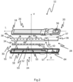
- the device 12 for sampling the figure 1 comprises the housing 16 comprising a lower element or housing base 24 and an upper element or cover 26 making it possible to close the top of the housing 16.
- the sampling device 12 comprises an absorbent assembly 28, extending along the longitudinal axis L, configured to be arranged in the housing 16.
- the sampling device 12 also comprises a strip 30 extending longitudinally and comprising on its upper face a plurality of reactive elements 32, 34 with color change arranged one after the other along the longitudinal axis L.
- a reactive element 32, 34 when brought into contact with a biological liquid, for example and without limitation, a change from orange color to blue for an indication of acidity (or also denoted 'pH') of the biological liquid, but still an appearance of color, that is to say from the white appearance of the reactive element 32, 34 to a pink color during the detection of nitrites in the biological liquid in contact with the adequate reactive element 32, 34.
- a strip 30 which can comprise ten reactive elements 32, 34 is compatible with the housing 16 and is suitable for a sufficiently exhaustive analysis of biological liquid.
- the absorbent assembly 28 like an absorbent paper capable of absorbing a liquid, has the role of receiving the biological liquid and diffusing it in contact with the reactive elements 32, 34.
- the The absorbent assembly 28 comprises an absorbent reservoir strip 36 intended for the deposition of biological liquid, and a diffusion strip 38 configured to diffuse by capillary action the biological liquid previously deposited on the absorbent reservoir strip 36 on the reactive elements 32, 34 of the strip 30.
- the absorbent reservoir strip 36 therefore comprises at least one portion configured to be in contact with the diffusion strip 38.
- the diffusion strip 38 and the absorbent reservoir strip 36 respectively comprise a diffusion blotting paper and a reservoir blotting paper distinct from the diffusion blotting paper, the reservoir blotting paper comprising a superior liquid absorption characteristic to that of diffusion blotting paper.
- the reservoir blotting paper must allow absorption of a quantity of biological liquid necessary for the analysis, and also allow rapid transfer of the biological liquid to the diffusion blotting paper.
- a reservoir blotting paper with a thickness between 2 and 3 millimeters, and with a liquid absorption characteristic of between 200 and 300 milligrams of liquid per square centimeter could be suitable for sampling device 12, this type of reservoir blotting paper comprising a liquid advancement speed of between 3 and 5 cm for a time of ten seconds.
- a diffusion blotting paper comprising a thickness less than a millimeter, preferably between 0.2 and 0.6 millimeter, and an absorption capacity of between 20 and 40 milligrams of liquid per square centimeter could be suitable for the device 12 sampling, this type of diffusion blotting paper comprising a liquid advancement speed of between 0.5 and 1.5 cm for a time of 10 seconds.
- the absorbent reservoir strip 36 and the diffusion strip 38 are arranged generally longitudinally one after the other.
- the absorbent reservoir strip 36 extending from the right lateral end 20 of the housing 16 to its second end forming a contact portion 40
- the diffusion strip 38 extending from the left lateral end 18 of the housing 16 to 'at its second end forming a contact pad 42.
- the contact portion 40 is configured to be in contact with the diffusion strip 38.
- the contact portion 40 is arranged over the contact pad 42 of the end of the broadcast band 38.
- the strip 30 is arranged below the diffusion strip 38. More particularly, the upper face of the strip 30, equipped with the plurality of reactive elements 32, 34 faces the lower face of the diffusion strip 38 so that the diffusion band 38 can come to bear on the reactive elements 32, 34, allowing a reaction of the reactive elements 32, 34 in contact with the biological liquid diffused by capillarity through the diffusion band 38.
- the diffusion of the biological liquid through the diffusion strip takes place from the contact portion 40 of the absorbent reservoir strip 36 in contact with the contact pad 42 of the end of the diffusion strip 38, up to the end opposite the contact area 40 of the diffusion band 38.
- the reactive elements 32, 34 are in contact with the diffusion band 38, they are in turn in contact with the biological liquid diffusing in the longitudinal direction D.
- the diffusion strip 38 comprises a plurality of reception areas 44, 46 arranged successively along the longitudinal axis L and separated from each other along the longitudinal axis L by a material recess 48, 50 of the strip diffusion strip 38.
- Each reactive element 32 is configured to be arranged in contact with a single reception area 44, the diffusion strip 38 comprising a material recess between each of the reception areas 44, 46.
- the reception areas 44, 46 are arranged along a longitudinal edge of the diffusion band 38, thus forming a series of reception areas 44, 46 in the form of successive slots.
- This embodiment allows the biological liquid to diffuse along the other longitudinal edge of the diffusion band 38, this other edge being opposite the edge forming the slots.
- the biological liquid can impregnate the reception areas 44, 46 successively and progressively one after the other.
- the strip 30 is configured to be arranged in the bottom of the housing 24 along the longitudinal axis L.
- the lower face of the strip 30, that is to say the face of the strip 30 opposite the face of the strip 30 on which the reactive elements 32, 34 are arranged, is arranged facing the bottom of the housing 24.
- the strip 30 is preferably a transparent strip 30, each reactive element 32, 34 of the strip being arranged, by transparency through the strip 30, facing an opening 52 in the bottom of the housing 24.
- the opening 52 of the housing bottom 24 is an opening 52 extending longitudinally, of a length along the longitudinal axis L slightly less than that of the strip 30 and of a width, in a direction transverse to the longitudinal axis L, slightly less than that of the strip 30, so that the strip 30 can come to rest on the periphery of the opening 52 of the housing base 24.
- the strip 30 is configured to be arranged between a first side wall 51 of a first edge of the housing bottom 24 extending longitudinally, and lateral stop pins 53 of the strip 30 arranged on the bottom of the housing 24.
- the strip 30 is configured to be arranged between a transverse wall 55 of the left end of the housing base 24 and another transverse wall 57, opposite the transverse wall 55 of the left end of the housing base 24, arranged on the housing base 24. It should be noted that the strip 30 makes it possible in particular to hold the elements reagents 32, 34 fixed in the housing 16, and to protect the reactive elements 32, 34 against impurities outside the housing 16
- the case back 24 is configured to be able to keep the diffusion band 38 fixed both against longitudinal movements and against lateral movements.
- the lateral stop pins 53 of the strip 30 are configured to be arranged between slots or material recesses 48, 50 of the diffusion strip 38.
- the edge of the diffusion strip 38 not having slots is configured to be arranged abutting against a second side wall 59 of the second edge of the housing base 24 extending longitudinally.
- the absorbent reservoir strip 36 is of generally parallelepiped shape.
- the housing base 24 comprises a plurality of transverse support tabs 64 extending between each longitudinal edge of the housing base 24 and projecting towards the interior of the housing 16.
- the transverse support tabs 64 of the plurality of transverse tabs 64 support are spaced regularly from the right lateral end 20 of the bottom of the housing 24 so as to be able to maintain the absorbent reservoir strip 36 in a balanced manner when closing the housing 16.
- the cover 26 of the housing 16 comprises a housing 54 configured to receive the absorbent tank strip 36.
- the housing 54 is formed by a reduction of material from the internal face of the cover 26.
- the housing 54 extends longitudinally from the end right side 20 of the cover 26 and is generally rectangular in shape making it possible to maintain fixed both against translational movements along the longitudinal axis L, and against lateral movements, the absorbent tank strip 36.
- the housing 54 of the absorbent tank strip 36 has an access opening 56 allowing direct access to a portion of the absorbent reservoir strip 36 from outside the housing 16 of the sampling device 12.
- the portion of the absorbent reservoir strip 36 arranged opposite the access opening 56 forms a portion 37 for depositing the biological liquid.
- the internal face of the cover 26 comprises support tabs 60 projecting from the internal face of the cover 26, the support tabs 60 extending longitudinally from the left lateral end 18 of the cover 26 to the housing 54 of the absorbent reservoir strip 36.
- the support tabs 60 form protruding patterns towards the inside of the housing 16, the tabs 60 being configured to rest on the diffusion strip 38.
- the internal face of the cover 26 comprises support pads 62 configured to bear against the reception areas 44, 46 of the diffusion strip 38.
- the absorbent reservoir strip 36 when the housing 16 is closed, that is to say when the periphery of the cover 26 is fixed with the periphery of the bottom of the housing 24, for example non-limiting, by clipping, the absorbent reservoir strip 36 is in contact with the diffusion strip 38, the diffusion strip 38 is in contact with the reactive elements 32, 34. More particularly, when the housing 16 is closed, the internal surface of the housing 54 rests on the absorbent reservoir strip 36. The absorbent reservoir strip 36 is therefore compressed between the internal surface of the housing 54 and the transverse tongues 64 so that the contact portion 40 of the absorbent reservoir strip 36 is in contact with support against the contact pad 42 of the diffusion strip 38. For this purpose , in the event of deposit of biological liquid on the deposit portion 37 of the sampling device 12, the biological liquid can diffuse from the absorbent reservoir strip 36 to the diffusion strip 38.
- the longitudinal support tabs 60 exert pressure on the diffusion strip 38 towards the bottom of the housing 24.
- the support pads 62 exert a force d support on the diffusion strip 38, allowing contact in support of the reception areas 44, 46 against the reactive elements 32, 34.
- the support force exerted by the longitudinal support tabs 60 associated with the force of The support exerted by the support pads 62 on the diffusion strip 38 allows reliable and durable support contact of the reception pads 44, 46 against the reactive elements 32, 34, thus allowing, in the event of the presence of liquid biological on the diffusion band 38, a reliable reaction of the reactive elements 32, 34 with the biological liquid which can result in a change of color of the reactive elements 32, 34.
- the strip 30, preferably transparent can be flexible in order to be able to withstand the assembly constraints of the sampling device 12.
- the strip 30 it is advantageous for the strip 30 to be a strip 30 of plastic material.
- Other material solutions such as for example, and not limited to, glass or even polymethyl methacrylate, could have been possible.
- the strip 30 may not necessarily be transparent, but only allow the passage of light, like a translucent material.
- the access opening 56 could also have been arranged on the bottom of the housing 24. Also, it could have been possible to provide a first access opening on the bottom of the housing 24 and a second access opening on the cover 26.
- a second embodiment of a sampling device 112 is shown.
- This second embodiment differs from the first embodiment in that the absorbent reservoir strip 136 is no longer arranged in a housing of the cover 126 fixed against translational movements.
- the absorbent element 128 includes an absorbent reservoir strip 136 arranged through a lateral access opening 156 arranged on the right lateral face of the right lateral end 120 of the housing 116 so that the biological liquid deposit portion 137 of the absorbent reservoir strip 136 is configured to be arranged outside the housing 116.
- the deposit portion 137 is advantageously configured to be covered by a cap 166 allowing the sampling device 112 to be handled manually without having to grasp the device 112 directly by touching the portion 137 deposit during its insertion into the reader 14.
- the absorbent reservoir strip 136 is arranged so as to be movable in translation along the longitudinal axis L.
- the absorbent reservoir strip 136 comprises from its left end to its right end, successively, a contact portion 140 configured to be in contact with the diffusion strip 138, a guide portion 168 in translation configured to be arranged in a guide ring 170, and the portion 137 for depositing biological liquid.
- the absorbent reservoir strip 136 and the diffusion strip 138 are arranged generally longitudinally one after the other in a manner generally similar to the first embodiment.
- the guide ring 170 is arranged integrally with the guide portion 168 of the absorbent tank strip 136.
- the guide ring 170 cooperates with guide rails extending inside the housing 116 from the side access opening 156.
- the guide ring 170 is configured to extend simultaneously inside the housing 116 so as to be partially arranged on its guide rails and also partially outside the housing 116 so as to form a first stop stop for the cap 166 when the latter is arranged in translation on the deposition portion 137.
- the guide ring 170 comprises an upper element and a lower element respectively comprising a male element such as a tenon and a female element, the guide portion 168 in translation of the absorbent reservoir strip 136 comprising a fixing opening 171 allowing the passage of the female element of the lower element through the absorbent tank band 136 in order to allow the coupling of the two elements of the guide ring 170.
- the guide ring 170 is configured to maintain the portion of guidance 168 during translation of the absorbent tank strip 136.
- the cover 126 of the housing comprises a support section 127 arranged over the reception areas 144, 146 of the diffusion band 138 and configured to come to bear on the reception areas 144, 146 of the diffusion band 138 when closing the housing 116 to bring the receiving areas 144, 146 into contact with the reactive elements 132, 134.
- the cover 126 of the housing includes a sliding section 129 arranged raised in relation to the support section 127 and configured for sliding in translation of the guide ring 170, the guide rails being arranged in this sliding section 129.
- the cover 126 comprises a sloping transition section 131 connecting the support section 127 and the sliding section 129.
- the contact pad 142 of the end of the diffusion strip 138 is arranged at least partially under the transition section of the cover 126.
- the contact portion 140 of the absorbent reservoir strip 136 is configured to be arranged out of contact with the contact pad 142 of the diffusion strip 138 according to an initial position of the guide ring 170. According to this initial position, the guide ring 170 forms a first stop for the cap 166 during its arrangement in translation on the deposition portion 137.
- the guide ring 170 is configured to be slid in translation towards the inside of the sliding section 129 by pushing action P on the cap 166 until the cap 166 abuts on the outer periphery of the opening d lateral access 156 of the housing 116, the periphery of the lateral access opening 156 forming a second stop for the cap 166.
- the contact portion 140 of the absorbent reservoir strip 136 hits the internal surface of the section transition 131 of the cover 126 so as to be folded in the direction of the contact area 142 of the diffusion strip 138.
- the internal surface of the transition section 131 is a bearing surface of the cover 126 for the contact portion 140 of the absorbent tank strip 136.
- the sliding section 129 may comprise a means for immobilizing the guide ring 170 of the notch type, the immobilizing means being configured to immobilize the guide ring 170 when it is pressed by the cap 166 in the stop position against the second stop stop.
- the immobilization means can advantageously only be operational up to a certain extraction force exerted on the cap 166 or directly on the deposit portion 137.
- the immobilization means may comprise at least one boss on a guide rail so that the guide ring 170 must be inserted with adequate force to override this boss. This boss can generate a tactile rendering of confirmation of effective insertion of the absorbent reservoir strip 136 into the sampling device 112 so as to ensure the contact portion 140 of the absorbent reservoir strip 136 with the beach contact 142 of the diffusion band 138.
- the second embodiment also differs from the first embodiment in that the housing bottom 124 comprises a plurality of housing bottom openings 152, 153 arranged one after the other along the longitudinal axis L.
- each reactive element 132, 134 of the strip 130 is arranged, by transparency through the strip 130, in with respect to a single opening 152 of the housing bottom 124 different from another opening 154 of the housing bottom 124 associated with another element reagent 134.
- a single housing bottom opening 124 extending longitudinally could be suitable, the solution consisting of a plurality of housing bottom openings 152, 154 124 makes it possible to robusten the overall structure of the case back 124.
- the second embodiment also differs from the first embodiment in that the upper surface of the cover 126 comprises a first boss 172 and a second boss 174, each boss 172, 174 projecting towards the outside of the housing 116.
- the first boss 172 is arranged in the vicinity of the free end of the support section 127 of the cover 126 so as to be aligned vertically with the left end of the diffusion strip 138, the second boss 174 being arranged astride the transition section 131 of the cover 126 and the support section 127 of the cover 126.
- the first boss 172 and the second boss 174 make it possible to guarantee flat maintenance along the longitudinal axis L of the diffusion strip 138 during its insertion in the portable reader 14 for analyzing a biological liquid sample, the first boss 172 and the second boss 174 being inserted in friction with a wall of the reader 14 so as to exert pressure on the diffusion strip 138.
- the first boss 172 and the second boss 174 also contribute to reinforcing the contact between the reception areas 144, 146 of the diffusion strip 138 on the reactive elements 132, 134. It will be appropriate, that depending on the length along the longitudinal axis L of the strip diffusion 138, a single boss or a plurality of bosses distributed on the upper surface of the cover 126 can also be suitable according to the invention.
- the first boss 172 and the second boss 174 make it possible to press the sampling device 112 on the base of the reader at the end of the stroke, the approach being done with play.
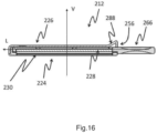
- a third embodiment of a sampling device 212 is shown.
- This third embodiment differs in particular from the first embodiment in that the housing 216 comprises a lateral access opening 256 arranged on the right side face of the right end 220 of the housing 216, in a manner similar to the second embodiment .
- the sampling device 212 comprises a handle 266 for handling the sampling device 212 configured to be arranged abutting against the periphery of the lateral access opening 256.
- the third embodiment differs from the second embodiment in that the handling handle 266 allows the complete insertion and extraction of the absorbent assembly 228 from the housing 216.
- the sampling device 212 comprises a removable support 276 of the absorbent assembly 228 configured to be inserted or extracted from the housing 216, the removable support 276 extending longitudinally from a first end comprising the handling handle 266 to its second end configured to be inserted into the housing 216 through the side access opening 256.
- the bottom of the housing 224 of the sampling device 212 has two opposite longitudinal walls sufficiently spaced from one another so as to form a slide 278 configured to guide the removable support 276 of the absorbent assembly 228 during its insertion in the housing 216.
- the strip 230 comprising the reactive elements 232, 234 is configured to be arranged longitudinally in the bottom of the housing 224, each of the ends of the strip 230 being configured to be held in a notch 280, 282 in the bottom of the housing 224 .
- the slide 278 and the removable support 276 of the absorbent assembly 228 may include immobilization means of the type of stop of the removable support 276, so as to keep the absorbent assembly 228 stationary when the handle 266 handling of the removable support 276 abuts against the periphery of the side access opening 256 of the housing 216.
- the face of the strip 230 not comprising any reactive elements 232, 234 is configured to be arranged to rest against the bottom of the housing 224 facing an opening 252 extending longitudinally, of a length along the longitudinal axis L slightly less than that of the strip 30 and of a width, in a direction transverse to the longitudinal axis L, slightly less than that of the strip 230, so that the strip 230 can come to rest on the periphery of the opening 252 of the housing base 224.
- the absorbent assembly 228 comprises a single absorbent element extending longitudinally and generally forming a parallelepiped element.
- the single absorbent element may be, for example non-limiting, of the reservoir blotting paper type.
- the single absorbent element acts as a diffusion band 238 and also allows the deposition of the biological liquid.
- the single absorbent element comprises a biological liquid deposition portion 237 and a diffusion band 238, the deposition portion 237 also being able to serve as a diffusion band 238.
- the removable support 276 is configured to hold the absorbent assembly 228 on its periphery so that its upper surface and its lower surface are directly accessible from above or below the support removable 276.
- the removable support 276 comprises retaining side walls 284 of the absorbent assembly 228, each retaining side wall 284 comprising edges 286 bearing on the upper surface and on the lower surface of the assembly absorbent 228.
- the portion 237 for depositing biological liquid can be as well defined on the upper or lower surface of the absorbent assembly 228 forming a single absorbent element, the diffusion band 238 being able to be identified as also being the upper surface or the lower surface of the absorbent assembly 228.
- slot-type patterns on one of the faces of the absorbent assembly 228 as illustrated on the diffusion band 38 of the first and second embodiment.
- a succession of zones reduced in thickness arranged successively along the longitudinal axis L on one face of the absorbent assembly 228 and each being separated by zones not reduced in thickness can form a diffusion band 238 in the shape of a crenel .
- the surface of the absorbent assembly 228 opposite the diffusion band 238 can therefore be defined as a deposition portion 237, the biological liquid being able to diffuse from the surface acting as a portion 237 deposited up to the surface acting as a diffusion band 238.
- the absorbent assembly 228 when the housing 216 is closed and the removable support 276 comprising the absorbent assembly 228 is entirely arranged in the housing 216, that is to say when the handle 266 abuts against the periphery of the lateral access opening 256, the absorbent assembly 228 is not in contact with the reactive elements 232, 234 of the strip 230.
- the distance d along the vertical axis V between the reactive elements 232, 324 and the surface of the absorbent assembly 228 forming the single absorbent element serving as a diffusion strip 238 may be less than a millimeter, this distance d being able to correspond to the thickness along the vertical axis V of the edges 286 of the side walls of maintaining 284 of the absorbent assembly 228.
- the sampling device 212 does not by itself allow the biological liquid to be brought into contact with the reactive elements 232, 234.
- the sampling device 212 of the third embodiment is configured so that the biological liquid only comes into contact with the reactive elements 232, 234 when this sampling device 212 is inserted into the reader 14 for analyzing a biological liquid sample.
- the cover 226 of the housing 216 comprises at its right end, in the vicinity of the lateral access opening 256, an oblique sloping portion 288 of the bevel type extending upwards from the surface of the cover 226 towards the opening of 256 side access.
- This oblique sloping portion is configured to abut against a wall of the reader 14 so as to progressively slide downwards the sampling device 212 in vertical thrust into contact with an internal stop of the analysis reader 14.
- the internal stop of the analysis reader 14 is then configured to crush the strip 230 towards the absorbent assembly 228 during the vertical downward thrust of the sampling device 12, the reactive elements 232, 234 of the strip 230 then being in compressed contact between the absorbent assembly 228 and the strip 230 arranged in direct support against an excrescence of the base of the analysis reader 14.
- the strip 230 is crushed, the two ends of the strip 230 are each ejected from their notch 280, 282 of the bottom of the housing 224 of the sampling device 212.
- a fourth embodiment of a sampling device 312 is shown.
- This fourth embodiment is a variant of the third embodiment.
- the housing 316 includes a side access opening 356 arranged on the right side face of the right end of the housing 316, similarly to the third embodiment.
- the sampling device 312 comprises a handling handle 366 allowing insertion in a longitudinal direction D1 and extraction in a direction opposite to D1 complete of the absorbent assembly 328 of the housing 316.
- the sampling device 312 comprises a removable support 376 of the absorbent assembly 328 configured to be inserted or extracted from the housing 316, the removable support 376 extending longitudinally from a first end comprising the handling handle 366 up to its second end configured to be inserted into the housing 316 through the side access opening 356.
- the housing 316 of the sampling device 312 comprises a top of the housing 324 and two longitudinal walls 323 opposite and sufficiently spaced from one another so as to form a slide 378 configured to guide the removable support 376 of the absorbent assembly 328 when it is inserted into the housing 316.
- the strip 330 comprising the reactive elements 332, 334 is configured to be arranged longitudinally at the top of the housing 324 between the two longitudinal walls 323 forming the slide 378 of the removable support 376 of the absorbent assembly 328, each of the ends of the strip 330 being configured to be held in a notch 380, 382 of the top of the housing 324.
- top of the housing or bottom of the housing of the housing of the device sampling of biological fluid can be considered equivalent, the overall orientation of the sampling device and the reader of the device being indications.
- the names simply allow an intuitive and clear description of the figures illustrating the invention. More generally, none of the overall orientations described of the sampling device is a limiting constraint on the invention.
- the slide 378 and the removable support 376 of the absorbent assembly 328 may include locking means of the removable support 376 type, so as to keep the absorbent assembly 328 stationary when the removable support 376 abuts against the periphery of the side access opening 356 of the housing 316.
- the removable support 376 comprises respectively from its first end to its second end, the handling handle 366 delimited by a guard element 377 preferably of trapezoidal shape and configured to close the opening of the reader case in which it is provided to introduce the biological sampling device 312, then a reception area 379 configured to arrange an electronic identification label 381 and forming a stop 383 of the removable support 376 against the housing 316 of the sampling device 312, and finally a support portion 385 of the absorbent assembly 328.
- the support portion 385 comprises a support tongue 329 of the absorbent assembly 328, that is to say a tongue 329 on which the absorbent assembly 328 rests, the tongue 329 of support which may include side walls 384 allowing the absorbent assembly 328 to be maintained on the tongue 329.
- the housing 316 of the sampling device 312 does not include a housing base, when the removable support 376 is inserted into the housing 316 of the device 312 of sampling, the tab 329 supporting the absorbent assembly 328 acts as the bottom of the housing of the sampling device 312.
- the face of the strip 330 not comprising any reactive elements 332, 334 is configured to be arranged to rest against the top of the housing 324 facing a plurality of openings 352, 354 high of housing 324. More particularly, in order to be able to read the change in color of the reactive elements 332, 334 arranged on the strip 330, each reactive element 332, 334 of the strip 330 is arranged, by transparency through the strip 330, facing a single opening 352 of the plurality of openings at the top of the housing 324, this single opening 352 being different from another opening 354 at the top of the housing 324 associated with another reactive element 334.
- the absorbent assembly 328 comprises a single absorbent element extending longitudinally and generally forming a parallelepiped element.
- the single absorbent element 328 can be, for example non-limiting, of the reservoir blotting paper type.
- the single absorbent element 328 acts as a diffusion band 338 and also allows the deposition of the biological liquid.
- the single absorbent element 328 comprises a biological liquid deposition portion 337 and a diffusion band 338, the deposition portion 337 serving as diffusion band 338.
- a transparent longitudinal section of the sampling device 312 and a reader 314 for analyzing a biological fluid sample according to the fourth embodiment is shown.
- the housing 316 is closed, that is to say when the removable support 376 comprising the absorbent assembly 328 is arranged abutting in the housing 316, the absorbent assembly 328 is not in contact with the reactive elements 332 , 334 of the strip 330.
- the distance d1 along the vertical axis V between the reactive elements 332, 324 and the surface of the absorbent assembly 328 serving as diffusion strip 338 can be less than a millimeter.
- the sampling device 312 does not by itself allow the biological liquid to be brought into contact with the reactive elements 332, 334.
- the sampling device 312 of the fourth embodiment is configured so that the biological liquid only comes into contact with the reactive elements 332, 334 when this sampling device 312 is inserted into the reader 314 for analyzing a biological liquid sample.
- the right end of the support tongue 329 of the absorbent assembly 328 comprises a beveled portion 357 of thickness, along the vertical axis, greater than the rest of the support tongue 329, the beveled portion comprising a downward slope towards the reception area 379 of the identification label 381.
- the beveled portion 357 is configured to abut on a first boss 315 of the sample analysis reader 314 before its complete insertion into the analysis reader 314 of sample, that is to say before the guard element 377 closes the opening of the reader box 314 for sample analysis.
- the absorbent assembly 328 is not in contact with the reactive elements 332, 334 of the strip 330.
- the opposite longitudinal walls 323 forming the slide 378 of the removable support 376 move away from each other so as to bring out the removable support 376 of the slide 378, the removable support 376 being pushed by the first boss 315 towards the reactive elements 332, 334 of the strip 330.
- sample analysis reader 314 may include a second embossment 317 configured to also raise the free end of the support tab 329 of the absorbent assembly 328 towards the reactive elements 332, 334 of the strip 330 and therefore improve the contact between the absorbent assembly 328 towards the reactive elements 332, 334 of the strip 330.
- each housing 16, 116, 216, 316 of each sampling device 12, 112, 212, 312 can also include a lug arranged on a wall of the housing 16, 116, 216, 316 of so as to form a detection stop cooperating with a position sensor of the analysis reader 14, 314, thus allowing the reader 14, 314 analysis to check the presence or non-presence of the sampling device 12, 112, 212, 312 correctly arranged in the analysis reader 14, 314.
- each housing 16, 116, 216, 316 of each sampling device 12, 112, 212, 312 can include an electronic identification label arranged for example stuck on the cover 26, 126 , 226, or according to the fourth embodiment, glued to the removable support 376, so as to guarantee traceability of each sampling device 12, 112, 212.
- the housing 216 more particularly the upper cover 226 of the housing may also include lateral guide fins 227 making it possible to facilitate the insertion of the sampling cartridge into the analysis reader 14, 314.
- the guide fins 227 are configured to be able to cooperate with guide means specific to the analysis reader 14, 314.
- the reader 14, 314 for analyzing the figure 1 may include several variants so as to be compatible with each of the embodiments.
- a non-limiting example is illustrated in figures 21, 22 and 23 .
- each reactive element 32, 132, 232, 332 is particularly suitable for optical reading by reflection of light on each reactive element 32, 132, 232, 332 through the openings 52, 152, 252, 352 of the bottom of the housing 24, 124 , 224, or the top of the housing 324 and the strip 30, 130, 230, 330 allowing detection by the reader 14, 314 for analyzing a change in color of the reactive elements 32, 132, 232, 332 and therefore allowing automatic analysis by the reader 14 of the properties of the sample of the biological liquid to be analyzed.
- the reactive elements 32, 132, 232, 332 change color on contact with urine, can for example and in a non-limiting manner, provide information relating to the monitoring of the acidity of urine via its hydrogen potential, noted pH, or the urinary density and its creatinine concentration. Uric acid concentration is also a possible monitoring factor.
Landscapes
- Health & Medical Sciences (AREA)
- Chemical & Material Sciences (AREA)
- Analytical Chemistry (AREA)
- General Health & Medical Sciences (AREA)
- Hematology (AREA)
- Clinical Laboratory Science (AREA)
- Chemical Kinetics & Catalysis (AREA)
- Investigating Or Analysing Biological Materials (AREA)
- Sampling And Sample Adjustment (AREA)
Claims (10)
- Vorrichtung (12, 112, 212, 312) zur Entnahme einer Probe einer biologischen Flüssigkeit, die dazu bestimmt ist, in ein tragbares Lesegerät (14, 314) zur Analyse der biologischen Flüssigkeit eingeführt werden zu können, wobei die Vorrichtung (12, 112, 212, 312) zur Entnahme Folgendes umfasst:- einen transparenten oder transluzenten Streifen (30, 130, 230, 330), der sich entlang einer Längsachse (L) erstreckt und auf seiner Oberseite eine Vielzahl von farbwechselnden reaktiven Elementen (32, 132, 232, 332) aufweist, die entlang der Längsachse (L) hintereinander angeordnet sind;- eine absorbierende Einheit (28; 128, 228, 328), sich entlang der Längsachse (L) erstreckend und umfassendo einen Abschnitt (37, 137, 237, 337) zur Ablagerung von biologischer Flüssigkeit;o einen Diffusionsstreifen (38, 138, 238, 338) für die biologische Flüssigkeit, der über der Vielzahl von reaktiven Elementen (32, 132, 232, 332) angeordnet ist;- ein Gehäuse (16, 116, 216, 316), das sich entlang der Längsachse (L) zwischen zwei seitlichen Enden erstreckt, wobei das Gehäuse (16, 116, 216) Folgendes umfasst:o einen Gehäuseboden (24, 124, 224, 324), wobei der Streifen (30, 130, 230, 330) in dem Gehäuseboden (24, 124, 224, 324) angeordnet ist, wobei die Unterseite des Streifens (30, 130, 230, 330) gegenüber dem Gehäuseboden (24, 124, 224, 324) angeordnet ist, wobei jedes reaktive Element (32, 132, 232, 332) durch den Streifen (30, 130, 230, 330) hindurch transparent gegenüber einer Öffnung (52, 152, 252, 352) des Gehäusebodens (24, 124, 224, 324) angeordnet ist;o einen oberen Deckel (26, 126, 226, 326), der über dem Diffusionsstreifen (38, 138, 238) angeordnet ist und mindestens ein vorspringendes Muster (60, 172, 288) aufweist, das eine erste Auflagefläche bildet, die konfiguriert ist, um den Diffusionsstreifen (38, 138, 238, 338) in Kontakt mit der Vielzahl von reaktiven Elementen (32, 132, 232, 332) zu drücken;o eine Zugriffsöffnung (56, 156, 256, 356), die konfiguriert ist, um auf den Streifen des Abschnitts (37, 137, 237, 337) zur Ablagerung von biologischer Flüssigkeit zuzugreifen.
- Vorrichtung (12, 112, 212, 312) nach Anspruch 1, dadurch gekennzeichnet, dass der Abschnitt (37, 137, 237, 337) zur Ablagerung von biologischer Flüssigkeit durch die Zugangsöffnung (56, 156, 256, 356) hindurch angeordnet ist.
- Vorrichtung (212, 312) nach einem der vorhergehenden Ansprüche, dadurch gekennzeichnet, dass die absorbierende Einheit (228) ein einzelnes Löschpapier ist.
- Vorrichtung (12, 112) nach einem der Ansprüche 1 oder 2, dadurch gekennzeichnet, dass- der Abschnitt (37, 137) zur Ablagerung der biologischen Flüssigkeit einen absorbierenden Reservoirstreifen (36, 136) aufweist, der sich von dem Diffusionsstreifen (38, 138) unterscheidet;- das Gehäuse (16, 216) eine zweite Auflagefläche (64, 131) aufweist, die so konfiguriert ist, dass sie mindestens einen Kontaktabschnitt (40, 140) des absorbierenden Reservoirstreifens (36, 136) in Kontakt mit einem Kontaktbereich (42, 131) des absorbierenden Reservoirstreifens (36, 136) drückt.
- Vorrichtung (112) nach Anspruch 4, dadurch gekennzeichnet, dass- der absorbierende Reservoirstreifen (136) und der Diffusionsstreifen (138) im Wesentlichen in Längsrichtung hintereinander angeordnet sind, wobei der Reservoirstreifen (136) entlang der Längsachse (L) translatorisch beweglich konfiguriert ist,- der Kontaktabschnitt (140) am Ende des absorbierenden Reservoirstreifens (136) angeordnet ist; wobei der Kontaktabschnitt (140) so konfiguriert ist, dass er durch Drücken entlang der Längsachse (L) des absorbierenden Reservoirstreifens (136) auf die zweite Auflagefläche (131) stößt, so dass er mit der Kontaktfläche (142) des Diffusionsstreifens (138) in Kontakt gebracht wird.
- Vorrichtung (12, 112) nach einem der Ansprüche 4 oder 5, dadurch gekennzeichnet, dass- der Diffusionsstreifen (38, 138) und der absorbierende Reservoirstreifen (36, 136) jeweils ein Diffusionslöschpapier und ein sich von dem Diffusionslöschpapier unterscheidendes Reservoirlöschpapier umfassen, wobei das Reservoirlöschpapier eine höhere Flüssigkeitsabsorptionseigenschaft als das Diffusionslöschpapier aufweist.
- Vorrichtung (12, 112, 212) nach einem der vorhergehenden Ansprüche, dadurch gekennzeichnet, dass- der Diffusionsstreifen (38, 138, 238) eine Vielzahl von Aufnahmeflächen (44, 144) aufweist, die aufeinanderfolgend entlang der Längsachse (L) angeordnet sind, wobei jedes reaktive Element (32, 132, 232) unter einer einzelnen Aufnahmefläche (44, 144) angeordnet ist, wobei der Diffusionsstreifen (38, 138, 238) eine Materialausnehmung zwischen jeder der Aufnahmeflächen (44, 144) aufweist.
- Vorrichtung (212) nach einem der vorhergehenden Ansprüche, dadurch gekennzeichnet, dass- die Zugangsöffnung auf einer der seitlichen Extremitäten (220) des Gehäuses (116, 216) angeordnet ist.
- Vorrichtung (212) nach Anspruch 8, dadurch gekennzeichnet, dass das Gehäuse (216) zwei gegenüberliegende Längswände im Inneren des Gehäuses (216) umfasst, die eine Schiene (278) bilden, die mit einem entfernbaren Träger (276) der absorbierenden Anordnung (228) zusammenwirkt, wobei der entfernbare Träger (276) konfiguriert ist, um durch die Zugangsöffnung (256) in das Gehäuse (224) eingeführt zu werden.
- Vorrichtung (12) nach einem der vorhergehenden Ansprüche 1 bis 7, dadurch gekennzeichnet, dass- die Zugangsöffnung (56) auf dem Gehäusedeckel (26) oder auf dem Gehäuseboden (24) angeordnet ist.
Applications Claiming Priority (2)
| Application Number | Priority Date | Filing Date | Title |
|---|---|---|---|
| FR1910242A FR3100889B1 (fr) | 2019-09-17 | 2019-09-17 | Dispositif de prélèvement d’échantillon liquide biologique |
| PCT/EP2020/075812 WO2021052984A1 (fr) | 2019-09-17 | 2020-09-16 | Dispositif de prélèvement d'échantillon liquide biologique |
Publications (4)
| Publication Number | Publication Date |
|---|---|
| EP4031867A1 EP4031867A1 (de) | 2022-07-27 |
| EP4031867C0 EP4031867C0 (de) | 2023-11-08 |
| EP4031867B1 true EP4031867B1 (de) | 2023-11-08 |
| EP4031867B8 EP4031867B8 (de) | 2023-12-13 |
Family
ID=68425143
Family Applications (1)
| Application Number | Title | Priority Date | Filing Date |
|---|---|---|---|
| EP20771859.4A Active EP4031867B8 (de) | 2019-09-17 | 2020-09-16 | Vorrichtung zur entnahme einer probe einer biologischen flüssigkeit |
Country Status (5)
| Country | Link |
|---|---|
| US (1) | US20220280934A1 (de) |
| EP (1) | EP4031867B8 (de) |
| JP (1) | JP7514915B2 (de) |
| FR (1) | FR3100889B1 (de) |
| WO (1) | WO2021052984A1 (de) |
Family Cites Families (8)
| Publication number | Priority date | Publication date | Assignee | Title |
|---|---|---|---|---|
| JP2953418B2 (ja) * | 1997-01-09 | 1999-09-27 | 日本電気株式会社 | 生化学分析装置 |
| JPH11248700A (ja) * | 1998-03-04 | 1999-09-17 | Toppan Printing Co Ltd | 尿検査片 |
| WO2000042430A1 (en) * | 1999-01-15 | 2000-07-20 | Medtox Scientific, Inc. | Lateral flow test strip |
| US6844149B2 (en) | 2001-06-29 | 2005-01-18 | International Business Machines Corporation | Method, system, and apparatus for measurement and recording of blood chemistry and other physiological measurements |
| GB2391813B (en) * | 2002-08-14 | 2006-03-29 | Cozart Bioscience Ltd | An oral fluid collection, transfer and transportation device and method |
| CN102401828B (zh) * | 2003-09-23 | 2014-08-06 | 美艾利尔瑞士股份有限公司 | 侧流式检测装置 |
| KR101816520B1 (ko) | 2015-12-29 | 2018-01-10 | 광주과학기술원 | 다중 분자진단을 위한 칩 구조 |
| WO2019245744A1 (en) * | 2018-06-18 | 2019-12-26 | Becton, Dickinson And Company | Systems, devices, and methods for amplifying signals of a lateral flow assay |
-
2019
- 2019-09-17 FR FR1910242A patent/FR3100889B1/fr active Active
-
2020
- 2020-09-16 WO PCT/EP2020/075812 patent/WO2021052984A1/fr not_active Ceased
- 2020-09-16 US US17/637,062 patent/US20220280934A1/en active Pending
- 2020-09-16 JP JP2022516401A patent/JP7514915B2/ja active Active
- 2020-09-16 EP EP20771859.4A patent/EP4031867B8/de active Active
Also Published As
| Publication number | Publication date |
|---|---|
| FR3100889B1 (fr) | 2021-09-10 |
| JP7514915B2 (ja) | 2024-07-11 |
| WO2021052984A1 (fr) | 2021-03-25 |
| EP4031867A1 (de) | 2022-07-27 |
| FR3100889A1 (fr) | 2021-03-19 |
| EP4031867C0 (de) | 2023-11-08 |
| JP2022548097A (ja) | 2022-11-16 |
| EP4031867B8 (de) | 2023-12-13 |
| US20220280934A1 (en) | 2022-09-08 |
Similar Documents
| Publication | Publication Date | Title |
|---|---|---|
| US8066957B2 (en) | Easy strip access primary container and methods of manufacturing and utilization thereof | |
| EP2764363B1 (de) | Anordnung zur bestimmung der an-oder abwesenheit eines analyten in einer blutprobe und analysevorrichtung mit einer solchen anordnung | |
| FR2672126A1 (fr) | Segment reactionnel pour analyseur automatique d'echantillons et analyseur equipe d'un segment. | |
| EP4031867B1 (de) | Vorrichtung zur entnahme einer probe einer biologischen flüssigkeit | |
| EP3317664B1 (de) | System zur analyse einer flüssigkeitsprobe | |
| EP4031855B1 (de) | Verfahren und tragbarer leser zum analysieren einer biologischen probe | |
| EP3423840B1 (de) | Automatisches analysesystem für in-vitro-diagnostik | |
| WO2001054817A2 (fr) | Cuvettes, appareil d'analyse biologique automatise utilisant de telles cuvettes, moyen de transfert de cuvettes dans un tel appareil et procede de transfert | |
| CA2162486A1 (fr) | Dispositif applicateur d'un element plat de prelevement de micro-organismes, tel qu'une boite de petri | |
| EP1870160A1 (de) | Verpackung für Entnahmegerät für Körper-Sekrete | |
| EP3317017A1 (de) | Vorrichtung zur analyse einer flüssigkeitsprobe mit einer verriegelungs- und entnahmevorrichtung | |
| EP3314263B1 (de) | Lateral-flow-vorrichtung mit probennahme | |
| FR2709250A1 (fr) | Dispositif pour sélectionner des spermatozoïdes. | |
| FR2934506A1 (fr) | Recipient pour produits reactifs | |
| US20110182785A1 (en) | Flat Pop-Up Primary Container And Methods of Manufacturing And Utilization Thereof | |
| FR2883375A1 (fr) | Emballage pour outil de prelevement de secretions corporelles | |
| EP1029446B1 (de) | Pflanzentopf mit Wasservorrat | |
| EP0442232A1 (de) | Vorrichtung zur Flüssigkeitsprobenanalyse | |
| FR3091184A1 (fr) | Plaque pour échantillons biologiques | |
| FR2656779A1 (fr) | Boitier pour le stockage des pieces, jetons, cartes, etiquettes.. ou articles similaires pouvant etre associes a un anneau porte-cle. | |
| FR2533347A1 (fr) | Conteneur pour videodisque | |
| Malabou | Philosophie française et nouvelles perspectives sur la pensée de la mort | |
| FR2752198A1 (fr) | Dispositif pour le pliage du papier a lettre | |
| Furrer | Théorie métaéthiques et motivation morale | |
| FR3104561A1 (fr) | Dispositif de stockage et de distribution de bandelettes |
Legal Events
| Date | Code | Title | Description |
|---|---|---|---|
| STAA | Information on the status of an ep patent application or granted ep patent |
Free format text: STATUS: UNKNOWN |
|
| STAA | Information on the status of an ep patent application or granted ep patent |
Free format text: STATUS: THE INTERNATIONAL PUBLICATION HAS BEEN MADE |
|
| PUAI | Public reference made under article 153(3) epc to a published international application that has entered the european phase |
Free format text: ORIGINAL CODE: 0009012 |
|
| STAA | Information on the status of an ep patent application or granted ep patent |
Free format text: STATUS: REQUEST FOR EXAMINATION WAS MADE |
|
| 17P | Request for examination filed |
Effective date: 20220329 |
|
| AK | Designated contracting states |
Kind code of ref document: A1 Designated state(s): AL AT BE BG CH CY CZ DE DK EE ES FI FR GB GR HR HU IE IS IT LI LT LU LV MC MK MT NL NO PL PT RO RS SE SI SK SM TR |
|
| DAV | Request for validation of the european patent (deleted) | ||
| DAX | Request for extension of the european patent (deleted) | ||
| GRAP | Despatch of communication of intention to grant a patent |
Free format text: ORIGINAL CODE: EPIDOSNIGR1 |
|
| STAA | Information on the status of an ep patent application or granted ep patent |
Free format text: STATUS: GRANT OF PATENT IS INTENDED |
|
| INTG | Intention to grant announced |
Effective date: 20230426 |
|
| GRAS | Grant fee paid |
Free format text: ORIGINAL CODE: EPIDOSNIGR3 |
|
| GRAA | (expected) grant |
Free format text: ORIGINAL CODE: 0009210 |
|
| STAA | Information on the status of an ep patent application or granted ep patent |
Free format text: STATUS: THE PATENT HAS BEEN GRANTED |
|
| AK | Designated contracting states |
Kind code of ref document: B1 Designated state(s): AL AT BE BG CH CY CZ DE DK EE ES FI FR GB GR HR HU IE IS IT LI LT LU LV MC MK MT NL NO PL PT RO RS SE SI SK SM TR |
|
| REG | Reference to a national code |
Ref country code: GB Ref legal event code: FG4D Free format text: NOT ENGLISH |
|
| RAP4 | Party data changed (patent owner data changed or rights of a patent transferred) |
Owner name: IKI |
|
| REG | Reference to a national code |
Ref country code: CH Ref legal event code: PK Free format text: RECTIFICATION B8 Ref country code: CH Ref legal event code: EP |
|
| REG | Reference to a national code |
Ref country code: DE Ref legal event code: R096 Ref document number: 602020020770 Country of ref document: DE |
|
| REG | Reference to a national code |
Ref country code: IE Ref legal event code: FG4D Free format text: LANGUAGE OF EP DOCUMENT: FRENCH |
|
| U01 | Request for unitary effect filed |
Effective date: 20231110 |
|
| U07 | Unitary effect registered |
Designated state(s): AT BE BG DE DK EE FI FR IT LT LU LV MT NL PT SE SI Effective date: 20231116 |
|
| PG25 | Lapsed in a contracting state [announced via postgrant information from national office to epo] |
Ref country code: GR Free format text: LAPSE BECAUSE OF FAILURE TO SUBMIT A TRANSLATION OF THE DESCRIPTION OR TO PAY THE FEE WITHIN THE PRESCRIBED TIME-LIMIT Effective date: 20240209 |
|
| PG25 | Lapsed in a contracting state [announced via postgrant information from national office to epo] |
Ref country code: IS Free format text: LAPSE BECAUSE OF FAILURE TO SUBMIT A TRANSLATION OF THE DESCRIPTION OR TO PAY THE FEE WITHIN THE PRESCRIBED TIME-LIMIT Effective date: 20240308 |
|
| PG25 | Lapsed in a contracting state [announced via postgrant information from national office to epo] |
Ref country code: ES Free format text: LAPSE BECAUSE OF FAILURE TO SUBMIT A TRANSLATION OF THE DESCRIPTION OR TO PAY THE FEE WITHIN THE PRESCRIBED TIME-LIMIT Effective date: 20231108 |
|
| PG25 | Lapsed in a contracting state [announced via postgrant information from national office to epo] |
Ref country code: IS Free format text: LAPSE BECAUSE OF FAILURE TO SUBMIT A TRANSLATION OF THE DESCRIPTION OR TO PAY THE FEE WITHIN THE PRESCRIBED TIME-LIMIT Effective date: 20240308 Ref country code: GR Free format text: LAPSE BECAUSE OF FAILURE TO SUBMIT A TRANSLATION OF THE DESCRIPTION OR TO PAY THE FEE WITHIN THE PRESCRIBED TIME-LIMIT Effective date: 20240209 Ref country code: ES Free format text: LAPSE BECAUSE OF FAILURE TO SUBMIT A TRANSLATION OF THE DESCRIPTION OR TO PAY THE FEE WITHIN THE PRESCRIBED TIME-LIMIT Effective date: 20231108 |
|
| PG25 | Lapsed in a contracting state [announced via postgrant information from national office to epo] |
Ref country code: RS Free format text: LAPSE BECAUSE OF FAILURE TO SUBMIT A TRANSLATION OF THE DESCRIPTION OR TO PAY THE FEE WITHIN THE PRESCRIBED TIME-LIMIT Effective date: 20231108 Ref country code: PL Free format text: LAPSE BECAUSE OF FAILURE TO SUBMIT A TRANSLATION OF THE DESCRIPTION OR TO PAY THE FEE WITHIN THE PRESCRIBED TIME-LIMIT Effective date: 20231108 Ref country code: NO Free format text: LAPSE BECAUSE OF FAILURE TO SUBMIT A TRANSLATION OF THE DESCRIPTION OR TO PAY THE FEE WITHIN THE PRESCRIBED TIME-LIMIT Effective date: 20240208 Ref country code: HR Free format text: LAPSE BECAUSE OF FAILURE TO SUBMIT A TRANSLATION OF THE DESCRIPTION OR TO PAY THE FEE WITHIN THE PRESCRIBED TIME-LIMIT Effective date: 20231108 |
|
| PG25 | Lapsed in a contracting state [announced via postgrant information from national office to epo] |
Ref country code: CZ Free format text: LAPSE BECAUSE OF FAILURE TO SUBMIT A TRANSLATION OF THE DESCRIPTION OR TO PAY THE FEE WITHIN THE PRESCRIBED TIME-LIMIT Effective date: 20231108 |
|
| PG25 | Lapsed in a contracting state [announced via postgrant information from national office to epo] |
Ref country code: SK Free format text: LAPSE BECAUSE OF FAILURE TO SUBMIT A TRANSLATION OF THE DESCRIPTION OR TO PAY THE FEE WITHIN THE PRESCRIBED TIME-LIMIT Effective date: 20231108 |
|
| PG25 | Lapsed in a contracting state [announced via postgrant information from national office to epo] |
Ref country code: SM Free format text: LAPSE BECAUSE OF FAILURE TO SUBMIT A TRANSLATION OF THE DESCRIPTION OR TO PAY THE FEE WITHIN THE PRESCRIBED TIME-LIMIT Effective date: 20231108 Ref country code: SK Free format text: LAPSE BECAUSE OF FAILURE TO SUBMIT A TRANSLATION OF THE DESCRIPTION OR TO PAY THE FEE WITHIN THE PRESCRIBED TIME-LIMIT Effective date: 20231108 Ref country code: RO Free format text: LAPSE BECAUSE OF FAILURE TO SUBMIT A TRANSLATION OF THE DESCRIPTION OR TO PAY THE FEE WITHIN THE PRESCRIBED TIME-LIMIT Effective date: 20231108 Ref country code: CZ Free format text: LAPSE BECAUSE OF FAILURE TO SUBMIT A TRANSLATION OF THE DESCRIPTION OR TO PAY THE FEE WITHIN THE PRESCRIBED TIME-LIMIT Effective date: 20231108 |
|
| REG | Reference to a national code |
Ref country code: DE Ref legal event code: R097 Ref document number: 602020020770 Country of ref document: DE |
|
| PLBE | No opposition filed within time limit |
Free format text: ORIGINAL CODE: 0009261 |
|
| STAA | Information on the status of an ep patent application or granted ep patent |
Free format text: STATUS: NO OPPOSITION FILED WITHIN TIME LIMIT |
|
| 26N | No opposition filed |
Effective date: 20240809 |
|
| U20 | Renewal fee for the european patent with unitary effect paid |
Year of fee payment: 5 Effective date: 20240926 |
|
| PG25 | Lapsed in a contracting state [announced via postgrant information from national office to epo] |
Ref country code: MC Free format text: LAPSE BECAUSE OF FAILURE TO SUBMIT A TRANSLATION OF THE DESCRIPTION OR TO PAY THE FEE WITHIN THE PRESCRIBED TIME-LIMIT Effective date: 20231108 |
|
| REG | Reference to a national code |
Ref country code: CH Ref legal event code: PL |
|
| GBPC | Gb: european patent ceased through non-payment of renewal fee |
Effective date: 20240916 |
|
| PG25 | Lapsed in a contracting state [announced via postgrant information from national office to epo] |
Ref country code: GB Free format text: LAPSE BECAUSE OF NON-PAYMENT OF DUE FEES Effective date: 20240916 |
|
| PG25 | Lapsed in a contracting state [announced via postgrant information from national office to epo] |
Ref country code: CH Free format text: LAPSE BECAUSE OF NON-PAYMENT OF DUE FEES Effective date: 20240930 |
|
| PG25 | Lapsed in a contracting state [announced via postgrant information from national office to epo] |
Ref country code: IE Free format text: LAPSE BECAUSE OF NON-PAYMENT OF DUE FEES Effective date: 20240916 |
|
| U20 | Renewal fee for the european patent with unitary effect paid |
Year of fee payment: 6 Effective date: 20250929 |
|
| U1N | Appointed representative for the unitary patent procedure changed after the registration of the unitary effect |
Representative=s name: SANTARELLI; FR |
|
| PG25 | Lapsed in a contracting state [announced via postgrant information from national office to epo] |
Ref country code: CY Free format text: LAPSE BECAUSE OF FAILURE TO SUBMIT A TRANSLATION OF THE DESCRIPTION OR TO PAY THE FEE WITHIN THE PRESCRIBED TIME-LIMIT; INVALID AB INITIO Effective date: 20200916 |
|
| PG25 | Lapsed in a contracting state [announced via postgrant information from national office to epo] |
Ref country code: HU Free format text: LAPSE BECAUSE OF FAILURE TO SUBMIT A TRANSLATION OF THE DESCRIPTION OR TO PAY THE FEE WITHIN THE PRESCRIBED TIME-LIMIT; INVALID AB INITIO Effective date: 20200916 |