EP4032601A1 - Verfahren zur konzentrierung von rohstofflösungen und system zur konzentrierung von rohstofflösungen - Google Patents
Verfahren zur konzentrierung von rohstofflösungen und system zur konzentrierung von rohstofflösungen Download PDFInfo
- Publication number
- EP4032601A1 EP4032601A1 EP20865822.9A EP20865822A EP4032601A1 EP 4032601 A1 EP4032601 A1 EP 4032601A1 EP 20865822 A EP20865822 A EP 20865822A EP 4032601 A1 EP4032601 A1 EP 4032601A1
- Authority
- EP
- European Patent Office
- Prior art keywords
- feed solution
- concentration
- concentrating
- solvent
- membrane
- Prior art date
- Legal status (The legal status is an assumption and is not a legal conclusion. Google has not performed a legal analysis and makes no representation as to the accuracy of the status listed.)
- Pending
Links
Images




Classifications
-
- B—PERFORMING OPERATIONS; TRANSPORTING
- B01—PHYSICAL OR CHEMICAL PROCESSES OR APPARATUS IN GENERAL
- B01D—SEPARATION
- B01D61/00—Processes of separation using semi-permeable membranes, e.g. dialysis, osmosis or ultrafiltration; Apparatus, accessories or auxiliary operations specially adapted therefor
- B01D61/002—Forward osmosis or direct osmosis
- B01D61/0024—Controlling or regulating
-
- B—PERFORMING OPERATIONS; TRANSPORTING
- B01—PHYSICAL OR CHEMICAL PROCESSES OR APPARATUS IN GENERAL
- B01D—SEPARATION
- B01D61/00—Processes of separation using semi-permeable membranes, e.g. dialysis, osmosis or ultrafiltration; Apparatus, accessories or auxiliary operations specially adapted therefor
-
- B—PERFORMING OPERATIONS; TRANSPORTING
- B01—PHYSICAL OR CHEMICAL PROCESSES OR APPARATUS IN GENERAL
- B01D—SEPARATION
- B01D61/00—Processes of separation using semi-permeable membranes, e.g. dialysis, osmosis or ultrafiltration; Apparatus, accessories or auxiliary operations specially adapted therefor
- B01D61/36—Pervaporation; Membrane distillation; Liquid permeation
- B01D61/364—Membrane distillation
- B01D61/3641—Membrane distillation comprising multiple membrane distillation steps
-
- B—PERFORMING OPERATIONS; TRANSPORTING
- B01—PHYSICAL OR CHEMICAL PROCESSES OR APPARATUS IN GENERAL
- B01D—SEPARATION
- B01D61/00—Processes of separation using semi-permeable membranes, e.g. dialysis, osmosis or ultrafiltration; Apparatus, accessories or auxiliary operations specially adapted therefor
- B01D61/58—Multistep processes
-
- C—CHEMISTRY; METALLURGY
- C02—TREATMENT OF WATER, WASTE WATER, SEWAGE, OR SLUDGE
- C02F—TREATMENT OF WATER, WASTE WATER, SEWAGE, OR SLUDGE
- C02F1/00—Treatment of water, waste water, or sewage
- C02F1/44—Treatment of water, waste water, or sewage by dialysis, osmosis or reverse osmosis
-
- C—CHEMISTRY; METALLURGY
- C07—ORGANIC CHEMISTRY
- C07C—ACYCLIC OR CARBOCYCLIC COMPOUNDS
- C07C253/00—Preparation of carboxylic acid nitriles
- C07C253/32—Separation; Purification; Stabilisation; Use of additives
- C07C253/34—Separation; Purification
-
- C—CHEMISTRY; METALLURGY
- C07—ORGANIC CHEMISTRY
- C07C—ACYCLIC OR CARBOCYCLIC COMPOUNDS
- C07C29/00—Preparation of compounds having hydroxy or O-metal groups bound to a carbon atom not belonging to a six-membered aromatic ring
- C07C29/74—Separation; Purification; Use of additives, e.g. for stabilisation
- C07C29/76—Separation; Purification; Use of additives, e.g. for stabilisation by physical treatment
- C07C29/86—Separation; Purification; Use of additives, e.g. for stabilisation by physical treatment by liquid-liquid treatment
-
- C—CHEMISTRY; METALLURGY
- C07—ORGANIC CHEMISTRY
- C07D—HETEROCYCLIC COMPOUNDS
- C07D209/00—Heterocyclic compounds containing five-membered rings, condensed with other rings, with one nitrogen atom as the only ring hetero atom
- C07D209/02—Heterocyclic compounds containing five-membered rings, condensed with other rings, with one nitrogen atom as the only ring hetero atom condensed with one carbocyclic ring
- C07D209/04—Indoles; Hydrogenated indoles
- C07D209/10—Indoles; Hydrogenated indoles with substituted hydrocarbon radicals attached to carbon atoms of the hetero ring
- C07D209/18—Radicals substituted by carbon atoms having three bonds to hetero atoms with at the most one bond to halogen, e.g. ester or nitrile radicals
- C07D209/20—Radicals substituted by carbon atoms having three bonds to hetero atoms with at the most one bond to halogen, e.g. ester or nitrile radicals substituted additionally by nitrogen atoms, e.g. tryptophane
-
- C—CHEMISTRY; METALLURGY
- C07—ORGANIC CHEMISTRY
- C07K—PEPTIDES
- C07K1/00—General methods for the preparation of peptides, i.e. processes for the organic chemical preparation of peptides or proteins of any length
- C07K1/14—Extraction; Separation; Purification
- C07K1/145—Extraction; Separation; Purification by extraction or solubilisation
-
- B—PERFORMING OPERATIONS; TRANSPORTING
- B01—PHYSICAL OR CHEMICAL PROCESSES OR APPARATUS IN GENERAL
- B01D—SEPARATION
- B01D2317/00—Membrane module arrangements within a plant or an apparatus
- B01D2317/02—Elements in series
- B01D2317/022—Reject series
-
- B—PERFORMING OPERATIONS; TRANSPORTING
- B01—PHYSICAL OR CHEMICAL PROCESSES OR APPARATUS IN GENERAL
- B01D—SEPARATION
- B01D2317/00—Membrane module arrangements within a plant or an apparatus
- B01D2317/08—Use of membrane modules of different kinds
-
- B—PERFORMING OPERATIONS; TRANSPORTING
- B01—PHYSICAL OR CHEMICAL PROCESSES OR APPARATUS IN GENERAL
- B01D—SEPARATION
- B01D61/00—Processes of separation using semi-permeable membranes, e.g. dialysis, osmosis or ultrafiltration; Apparatus, accessories or auxiliary operations specially adapted therefor
- B01D61/002—Forward osmosis or direct osmosis
- B01D61/0022—Apparatus therefor
-
- B—PERFORMING OPERATIONS; TRANSPORTING
- B01—PHYSICAL OR CHEMICAL PROCESSES OR APPARATUS IN GENERAL
- B01D—SEPARATION
- B01D61/00—Processes of separation using semi-permeable membranes, e.g. dialysis, osmosis or ultrafiltration; Apparatus, accessories or auxiliary operations specially adapted therefor
- B01D61/36—Pervaporation; Membrane distillation; Liquid permeation
- B01D61/366—Apparatus therefor
Definitions
- the present invention relates to a concentration method and a concentration system for a feed solution containing water and an organic solvent as a solvent.
- the solvent in the feed solutions to be concentrated may contain both water and an organic solvent.
- the peptides are widely used as diagnostic/test drugs and pharmaceuticals, and the feeds thereof are very expensive. Therefore, when concentrating feed solutions containing peptide, etc., it is important to recover the peptides in high yield without denaturation.
- a membrane filtration method using an ultrafiltration membrane As one method for stably and efficiently concentrating feed solutions containing the peptides, a membrane filtration method using an ultrafiltration membrane is used. Since the membrane filtration method using an ultrafiltration membrane, which is a technique for separating a feed solution by sieving, does not involve a temperature change, it is possible to reduce energy load. In the membrane filtration method using an ultrafiltration membrane, components having a size larger than the cut-off molecular weight of the membrane are retained, but water passes through the membrane. Thus, this method is effective for concentrating the peptides (PTL 1).
- a reverse osmosis (RO) method using a membrane which allows a solvent to permeate at a molecular level is known.
- the RO method is a method for concentrating a feed solution, configured such that the feed solution is pressurized to a predetermined pressure higher than the osmotic pressure of the feed solution and then supplied to an RO membrane module, where only the solvent in the feed solution permeates the RO membrane, thereby removing the solvent (typically water) in the feed solution (PTL 2).
- a forward osmosis (FO) method is known as another concentration method for a feed solution.
- the FO method is a concentration method for a feed solution, wherein a feed solution is brought into contact with a draw solution having a higher osmotic pressure than the feed solution via a forward osmotic (FO) membrane, and the solvent is diffused from the feed solution to the draw solution. Since the FO method does not require pressurization, it is expected that the solute contained in the feed solution can be efficiently concentrated without adhesion (PTL 3).
- membrane distillation (MD) methods are known.
- DCMD method Direct Contact MD
- a feed solution is concentrated by bringing the feed solution into contact with cooling water having a temperature lower than the feed solution and thereby transferring the vapor of the solvent in the feed solution from the feed solution to the cooling water, is well known (PTL 4).
- PTL 5 discloses a method in which a forward osmosis method and membrane distillation are combined.
- the membrane distillation method is used to regenerate the draw solution used in the forward osmosis method.
- the membrane distillation method is used to regenerate the draw solution used for forward osmosis and is not applied to concentrating the feed solution.
- An object of the present invention is to provide a concentration method and a concentration system for a feed solution, which are capable of concentrating a feed solution without the conditions of pressurization and heating and capable of controlling the ratio of water and an organic solvent in the feed solution after concentrating to any ratio.
- the present invention has been made to achieve the above object.
- the present inventors have discovered that when concentrating a feed solution containing water and an organic solvent as a solvent, by combining a concentration method of removing mainly water in the feed solution and a concentration method of removing mainly the organic solvent, the ratio of water and the organic solvent can be adjusted to any ratio, thus arriving at the present invention.
- the feed solution can be concentrated without heating and pressurization, and the solvent composition can be adjusted during concentration. Therefore, solvent replacement after the concentrating step is not necessary, and a closed-system apparatus can be configured so that the loss of feed components is small and the concentration treatment can be carried out in a short time.
- concentration apparatus of the present invention When the concentration apparatus of the present invention is used, a concentration system for a feed solution having the advantages as described above can be constructed.
- the concentration system for a feed solution of the present invention is a concentration system for a feed solution by concentrating a feed solution containing a solute and a solvent to obtain a concentrate of the feed solution, wherein
- the above first concentrating means is carried out by a forward osmosis method.
- water which has a smaller molecular size, tends to be preferentially removed in the forward osmosis method of the first concentrating means.
- the second evaporating means is carried out by a method of removing the solvent through evaporation.
- the solvent Of water and the organic solvent, the one having a higher vapor pressure is preferentially removed in the second concentrating means.
- the proportion of the organic solvent removed is generally higher.
- the concentration system of the present invention carried out as a combination of these means, not only simply carries out concentration, but can carry out concentration while optionally controlling the ratio of water and the organic solvent in the solvent in the feed solution to be concentrated.
- the first concentrating means in the concentration system for a feed solution of the present invention is a forward osmosis method that uses a forward osmotic membrane.
- FIG. 1 is a schematic diagram showing the action mechanism of the concentration method that uses a forward osmotic membrane.
- a forward osmotic membrane (120) makes contact with a feed solution (a) on one side of the membrane and with a draw solution (d) having a higher osmotic pressure than the feed solution on the opposite side.
- the forward osmotic membrane (120) of FIG. 1 comprises a substrate layer (121) and an active layer (122) formed on one side of the substrate layer (121).
- the active layer (122) has a very dense structure which is mainly permeable to water and is not permeable to a solute, and is formed on the surface of the substrate layer (121) on the side in contact with the feed solution (a).
- an ultrafiltration membrane As the material of the substrate layer (121), an ultrafiltration membrane is generally used.
- the draw solution (d) permeates a portion of the substrate layer (121), composed of the ultrafiltration membrane, of the forward osmotic membrane (120), and the feed solution (a) is brought into contact with the draw solution (d) via the active layer (122).
- a solvent mainly water, in the feed solution (a) is transferred to the side of the draw solution (d) having a higher osmotic pressure, and concentration is carried out.
- the form of the forward osmotic membrane may be any of, for example, a hollow-fiber membranous, a tubular, and a flat membranous structure.
- the hollow-fiber membranous forward osmotic membrane is suitable since a flow path through which the feed solution and the draw solution pass can be formed without using a spacer, and uniform concentration can be carried out.
- the material of the ultrafiltration membrane constituting the substrate layer can be selected from materials that are widely used. However, a material that dissolves or swells in an organic solvent in the solvent contained in the feed solution and cannot maintain pore shape of the membrane cannot be used.
- the material of the ultrafiltration membrane preferably has a thin membrane layer composed of at least one selected from the group consisting of, for example, polyethersulfone, polysulfone, polyketone, polyether ether ketone, polyphenylene ether, polyvinylidene fluoride, polyacrylonitrile, polyimine, polyimide, polybenzoxazole, polybenzimidazole, sulfonated tetrafluoroethylene, and polyamide as a main component.
- a thin membrane layer composed of at least one selected from the group consisting of, for example, polyethersulfone, polysulfone, polyketone, polyether ether ketone, polyphenylene ether, polyvinylidene fluoride, polyacrylonitrile, polyimine, polyimide, polybenzoxazole, polybenzimidazole, sulfonated tetrafluoroethylene, and polyamide as a main component.
- the material of the active layer mainly uses polyamide.
- the active layer composed of polyamide can be formed by interfacial polymerization of a polyfunctional acid halide and a polyfunctional aromatic amine on the substrate layer.
- the polyfunctional aromatic acid halide is an aromatic acid halide compound having two or more acid halide groups in one molecule. Specific examples thereof include a trimesic acid halide, a trimellitic acid halide, an isophthalic acid halide, a terephthalic acid halide, a pyromellitic acid halide, a benzophenonetetracarboxylic acid halide, a biphenyldicarboxylic acid halide, a naphthalenedicarboxylic acid halide, a pyridinedicarboxylic acid halide, and a benzenedisulfonic acid halide, which can be used alone or in a mixture thereof.
- halide ion in the aromatic acid halide compounds examples include chloride ion, bromide ion, and iodide ion.
- chloride ion bromide ion
- iodide ion particularly trimesic acid chloride alone, a mixture of trimesic acid chloride and isophthalic acid chloride, or a mixture of trimesic acid chloride and terephthalic acid chloride is preferably used.
- the polyfunctional aromatic amine is an aromatic amine compound having two or more amine groups in one molecule.
- Specific examples thereof include m-phenylenediamine, p-phenylenediamine, 3,3'-diaminodiphenylmethane, 4,4'-diaminodiphenylamine, 4,4'-diaminodiphenyl ether, 3,4'-diaminodiphenyl ether, 3,3'-diaminodiphenylamine, 3,5-diaminobenzoic acid, 4,4'-diaminodiphenyl sulfone, 3,3'-diaminodipheny sulfone, 3,4'-diaminodiphenyl sulfone, 1,3,5-triaminobenzene, and 1,5-diaminonaphthalene, which can be used alone or in a mixture thereof.
- the interfacial polymerization of the polyfunctional acid halide and the polyfunctional aromatic amine can be carried out according to a conventional method.
- the outer diameter of the hollow-fiber membrane is, for example, 300 ⁇ m to 5,000 ⁇ m, preferably 350 ⁇ m to 4,000 ⁇ m.
- the inner diameter of the hollow-fiber membrane is, for example, 200 ⁇ m to 4,000 ⁇ m, preferably 250 ⁇ m to 1,500 ⁇ m.
- inorganic salts such as sodium chloride, magnesium chloride, calcium chloride, sodium sulfate, magnesium sulfate, and potassium sulfate
- citrates such as sodium citrate and magnesium citrate
- acetates such as sodium acetate and magnesium acetate
- hydroxycarboxylic acids such as gluconic acid, lactic acid, glycolic acid, and glyceric acid
- the organic solvent used as a solute is typically an alcohol, and is preferably methanol, ethanol, isopropanol, or t-butanol, and is particularly preferably isopropanol.
- Isopropanol has an appropriate vapor pressure and does not azeotrope with water, and thus can be easily removed from the feed solution by a second concentration method comprising an evaporating means, even when mixed into the feed solution during concentration.
- the feed solution be, for example, a pharmaceutical product or a pharmaceutical feed, from the viewpoint of obtaining a high-purity concentrate.
- Examples of the solvent of the draw solution include water and alcohols, and may be one or more selected from thereamong.
- the alcohol include polyhydric alcohols such as monohydric alcohols, dihydric alcohols, trihydric alcohols, tetrahydric alcohols, pentahydric alcohols, and hexahydric alcohols; glyercin, t-butyl alcohol, isopropanol, xylitol, sorbitol, mannitol, perseitol, volemitol, and D-erythro-D-galacto-octitol.
- the solvent of the draw solution is typically water.
- an alcohol can be used as a solute and a solvent of the draw solution.
- the solvent of the draw solution is preferably water.
- the draw solution is particularly preferably an aqueous solution of isopropanol.
- the solute of the draw solution is preferably a hydroxycarboxylic acid or a solid organic substance at room temperature.
- the driving force for moving the solvent from the feed solution to the draw solution in the forward osmosis method is the osmotic pressure difference between the feed solution and the draw solution, it is necessary to renew the liquid between the active layer of the forward osmotic membrane and the interface of the feed solution or the draw solution. Therefore, it is necessary to flow the feed solution and the draw solution at an appropriate flow rate.
- the feed solution (a) and the draw solution (d) are opposing flows, but may be parallel flows.
- FIG. 3 is a schematic diagram showing one example of a forward osmotic membrane module, preferably applied as the first concentrating means of the concentration system for a feed solution of the present invention.
- a plurality of hollow-fiber forward osmotic membranes (120) are stored in a housing (110). Both ends of each forward osmotic membrane (120) are adhesively fixed to the housing (110) with an adhesive resin (130).
- Two housing side pipes are located on a side surface of the housing (110). Of the housing side pipes, one is the draw solution inlet (111) and the other is the draw solution outlet (112).
- the interior of the housing (110) is split in two: a space through which the feed solution (a) flows and a space through which the draw solution (d) flows, by an outer wall of the forward osmotic membrane (120) and the adhesive resin (130). Except that the solvent can travel through an inner wall of the forward osmotic membrane (120), both spaces are fluidly shielded.
- a feed solution (a) When a feed solution (a) is introduced from one end of the forward osmotic membrane module (100), the feed solution (a) flows into the inside of the membrane of the hollow-fiber forward osmotic membrane (120) and flows out from the other end surface.
- the feed solution (a) can be brought into contact with the draw solution (d) via the forward osmotic membrane (120).
- the solvent mainly water
- the feed solution (a) is brought into contact with the draw solution (d) via the forward osmotic membrane (120).
- the solvent mainly water
- Concentration is carried out by such a mechanism in the forward osmotic membrane method.
- the flow direction of the feed solution (a) and the flow direction of the draw solution (d) in the forward osmotic membrane module (100) of FIG. 3 are opposite, but may be parallel.
- the material of the housing (110) of the forward osmotic membrane module (100) of FIG. 3 is selected from the viewpoint of chemical resistance, pressure resistance, heat resistance, impact resistance, and weather resistance, wherein components contained in the feed solution (a) and the draw solution (d) do not deteriorate various performances.
- a resin or a metal can be used as the material of the housing (110). From the above viewpoint, it is preferable to select a resin such as polypropylene, polysulfone, polyethersulfone, polyvinylidene fluoride, ABS resin, a fiber-reinforced plastic, or vinyl chloride; or a metal such as stainless steel, brass, or titanium.
- the adhesive resin (130) in FIG. 3 it is desirable to have satisfactory mechanical strength and heat resistance at 100 °C.
- the resin which can be used as the adhesive resin (130) include a thermosetting epoxy resin and a thermosetting urethane resin. From the viewpoint of heat resistance, an epoxy resin is preferable. From the viewpoint of handleability, a urethane resin is preferable.
- the method of adhesively fixing the forward osmotic membrane (120) to the housing (110) may be a known bonding method relating to the production of a hollow-fiber membrane module.
- the first concentrating means in the concentration system for a feed solution of the present invention is a concentrating means of removing water and an inorganic solvent in the feed solution through evaporation.
- a concentrating means examples include an evaporator, a thin-membrane distillation apparatus, a method of flowing a gas into a container charged with the feed solution to transfer the solvent out of the container, and a membrane distillation method.
- a membrane distillation method facilitates the adjustment of the ratio of water and the organic solvent removed from the feed solution, and is thus a particularly effective concentrating means.
- FIG. 2 is a schematic diagram showing the action mechanism of the concentration method that uses a membrane distillation method.
- a membrane (220) for membrane distillation comes into contact with the feed solution (a) on one side of the membrane and a cooling water (CW) having a temperature lower than the feed solution (a) on the opposite side.
- the temperature of the feed solution (a) is higher, and thus the solvent (b) has a higher vapor pressure.
- the solvent (b) in the feed solution (a) evaporates to form vapor, and is transferred to the cooling water (CW) side via the membrane (220) for membrane distillation to be liquefied, thereby facilitating concentration.
- both water and the organic solvent in the solvent (b) of the feed solution (a) are removed through evaporation.
- the one having a higher vapor pressure is preferentially removed.
- the organic solvent generally has a higher vapor pressure, and thus the proportion of the organic solvent removed is higher.
- a VMD (Vacuum MD) method in place of bringing the feed solution (a) and the cooling water (CW) into contact with each other via the membrane, a VMD (Vacuum MD) method, in which vapor is extracted by putting the feed solution (a) and the opposite side of the membrane in a reduced pressure state, can be applied.
- VMD Vauum MD
- the membrane for membrane distillation It is necessary for the membrane for membrane distillation to allow only the vapor of the solvent, not the feed solution, to pass therethrough.
- the feed solution having a high proportion of the organic solvent in the solvent, since the surface tension of the feed solution is low, the feed solution enters the pores of the membrane for membrane distillation and flows to the cooling water side as-is, and so-called "wetting" may occur.
- wetting occurs, the membrane for membrane distillation loses the concentrating function thereof.
- a highly hydrophobic membrane is used as the membrane for membrane distillation.
- a water contact angle is used as a method to express hydrophobicity.
- hydrophobicity is evaluated by the contact angle between a water droplet disposed on a surface of the membrane and the membrane.
- the membrane for the membrane distillation method used as the second concentrating means of the present invention preferably has a water contact angle of 90° or greater, more preferably 110° or greater, and even more preferably 120° or greater. There is no upper limit to the water contact angle, but realistically the upper limit is about 150°.
- the distillation is carried out at a low vapor pressure compared to high-temperature distillation. Therefore, as the property of the membrane for membrane distillation in the present invention, it is necessary for the vapor permeation resistance to be as low as possible. From this viewpoint, the pores of the membrane for membrane distillation are preferably as large as possible without wetting.
- the average pore size is preferably in the range of 0.02 ⁇ m to 0.5 ⁇ m, more preferably 0.05 ⁇ m to 0.3 ⁇ m. When the average pore size of the membrane for membrane distillation is less than 0.02 ⁇ m, the vapor permeation resistance is too high and a long concentrating time is required. When the value is greater than 0.5 ⁇ m, the possibility of wetting becomes high and stable concentration cannot be carried out.
- any of a hollow-fiber membranous, a tubular, and a flat membranous shape can be applied.
- the porosity of the membrane for membrane distillation is preferably 60% or greater, more preferably 70% or greater, from the viewpoint of obtaining high vapor permeability.
- the porosity is preferably 90% or less, more preferably 85% or less.
- the membrane thickness is preferably 10 ⁇ m to 1,000 ⁇ m, more preferably 20 ⁇ m to 500 ⁇ m, from the viewpoint of achieving both vapor permeability and mechanical strength of the membrane.
- the membrane thickness is 1,000 ⁇ m or less, high vapor permeability can be obtained.
- the membrane thickness is 10 ⁇ m or greater, the membrane can be used without deformation.
- the outer diameter of the hollow-fiber membranous membrane for membrane distillation is preferably 300 ⁇ m to 5,000 ⁇ m, more preferably 350 ⁇ m to 4,000 ⁇ m, and the inner diameter is preferably 200 ⁇ m to 4,000 ⁇ m, more preferably 250 ⁇ m to 3,000 ⁇ m.
- the hollow-fiber membrane is set to the sizes in these ranges, the balance of membrane strength and effective area of the membrane becomes satisfactory.
- the material of the membrane for membrane distillation can be selected from ones comprising at least one resin selected from the group consisting of polysulfone, polyethersulfone, polyethylene, polypropylene, polyvinylidene fluoride, polytetrafluoroethylene, an ethylene/tetrafluoroethylene copolymer, and polychlorotrifluoroethylene. From the viewpoint of hydrophobicity, membrane formability, and mechanical and thermal durability, it is preferable to select and use polyvinylidene fluoride, an ethylene/tetrafluoroethylene copolymer, and polychlorotrifluoroethylene.
- a membrane for membrane distillation having a hydrophobic polymer attached to at least a portion thereof can be used.
- the hydrophobic polymer may be, for example, a polymer having a hydrophobic structure.
- the hydrophobic structure include a non-polar group or a weakly polar group, and a non-polar skeleton or a weakly polar skeleton.
- the non-polar group or the weakly polar group include a hydrocarbon group and a fluorine-containing group.
- Examples of the non-polar skeleton or the weakly polar skeleton include a hydrocarbon backbone and a siloxane backbone.
- hydrophobic polymer examples include a polymer having a siloxane bond and a fluorine atom-containing polymer, and more specifically include the following:
- the hydrophobic polymer is preferably a polymer of a (meth)acrylate-based monomer and/or a vinyl-based monomer, having a (per)fluoroalkyl group and/or a (per)fluoropolyether group having 1 to 12 carbon atoms.
- FIG. 4 is a schematic diagram showing one example of a membrane module for membrane distillation, preferably applied as the second concentrating means of the concentration system for a feed solution of the present invention.
- a plurality of hollow-fiber membranes (220) for membrane distillation are stored in a housing (210). Both ends of each membrane (220) for membrane distillation are adhesively fixed to the housing (210) with an adhesive resin (230).
- Two housing side pipes are located on a side surface of the housing (210). Of the housing side pipes, one is the cooling water inlet (211) and the other is the cooling water outlet (212).
- the interior of the housing (210) is split in two: a space through which the feed solution (a) flows and a space through which the cooling water (CW) flows, by an outer wall of the membrane (220) for membrane distillation and the adhesive resin (230). Except that the solvent can travel through an inner wall of the membrane (220) for membrane distillation, both spaces are fluidly shielded.
- feed solution (a) When a feed solution (a) is introduced from one end of the membrane module (500) for membrane distillation, the feed solution (a) flows into the inside of the membrane of the hollow-fiber membrane (220) for membrane distillation and flows out from the other end surface.
- the cooling water (CW) flows from the cooling water inlet (211) of the side pipes of the housing (210), the cooling water (CW) flows into the outside space of the hollow-fiber membrane (220) for membrane distillation and flows out from the cooling water outlet (212).
- the feed solution (a) can be brought into contact with the cooling water (CW) via the membrane for membrane distillation (120). Vapor of the solvent is transferred from the feed solution (a) to the cooling water (CW) by the difference in osmotic pressure of the two liquids and liquefied in the cooling water (CW), and the feed solution (a) is concentrated thereby.
- both water and the organic solvent of the solvent (b) in the feed solution (a) evaporate, pass through the membrane (220) for membrane distillation as vapor, and are transferred to the cooling water (CW).
- the ratio of the moving water and the organic solvent is determined by the magnitude of the vapor pressures of both thereof, and normally the organic solvent is preferentially transferred, as described above.
- the flow direction of the feed solution (a) and the flow direction of the cooling water (CW) in the membrane module (500) for membrane distillation of FIG. 4 are opposite, but may be parallel.
- the temperatures of the feed solution (a) and the cooling water (CW) are not particularly limited, but are preferably set to ranges that do not change the composition of the solute of the feed solution (a).
- the material of the housing (210) of the membrane module (500) for membrane distillation of FIG. 4 is selected from the viewpoint of chemical resistance, pressure resistance, heat resistance, impact resistance, and weather resistance, wherein components contained in the feed solution (a) and the cooling water (CW) do not deteriorate various performances.
- a resin or a metal can be used as the material of the housing (210). From the above viewpoint, it is preferable to select a resin such as polypropylene, polysulfone, polyethersulfone, polyvinylidene fluoride, ABS resin, a fiber-reinforced plastic, or vinyl chloride; or a metal such as stainless steel, brass, or titanium.
- the adhesive resin (230) in FIG. 4 it is desirable to have satisfactory mechanical strength and heat resistance at 100 °C.
- the resin which can be used as the adhesive resin (230) include a thermosetting epoxy resin and a thermosetting urethane resin. From the viewpoint of heat resistance, an epoxy resin is preferable. From the viewpoint of handleability, a urethane resin is preferable.
- the method of adhesively fixing the membrane (220) for membrane distillation to the housing (210) may be a known bonding method relating to the production of a hollow-fiber membrane module.
- FIGS. 5 to 10 show concentration systems of the present invention.
- the concentration system of FIG. 5 is an example in which a method of flowing a gas into a container charged with the feed solution to transfer the solvent out of the container is applied as the second concentrating means.
- the system of FIG. 5 comprises a forward osmotic membrane module (100), a feed solution tank (200), a draw solution tank (300), and a trap (400), wherein the feed solution tank (200) is mounted with a blower (BL).
- a forward osmotic membrane module 100
- a feed solution tank 200
- a draw solution tank 300
- a trap 400
- the feed solution tank 200
- BL blower
- the feed solution (a) is sent at a suitable flow rate by a pump (P) from a lower portion of the feed solution tank (200) filled with the feed solution (a) to one of the spaces (for example, a space on the side of the hollow-fiber forward osmotic membrane) of the forward osmotic membrane module (100).
- the flow rate of the feed solution (a) is manually or automatically regulated by a flow meter (not shown).
- the draw solution (d) is supplied by a pump (P) from the draw solution tank (300) filled with the draw solution (d) to another space (for example, an outside space of the hollow-fiber forward osmotic membrane) of the forward osmotic membrane module (100).
- the concentrated feed solution (a) exits from the forward osmotic membrane module (100) and is returned to the feed solution tank (200) to be circulated.
- the composition of the solvent (b) in the feed solution (a) after concentration generally has a high proportion of the organic solvent.
- a blower (BL) is provided in the feed solution tank (200), and air is sent into the feed solution tank (200) by the blower.
- the introduced air and the solvent vapor evaporated by the air are discharged out of the feed solution tank (200), thereby facilitating concentration.
- concentration with a stable composition can be carried out by providing the feed solution tank (200) with a stirring function as needed.
- the concentration by the second concentrating means both water and the organic solvent are removed.
- the organic solvent having a high vapor pressure is preferentially removed, and thus the composition of the solvent (b) in the feed solution (a) after concentration generally has a high proportion of water.
- the concentration system of FIG. 6 is an example in which a membrane distillation method is applied as the second concentrating means.
- the system of FIG. 6 comprises a forward osmotic membrane module (100), a feed solution tank (200), a draw solution tank (300), a membrane module (500) for membrane distillation, and a cooling water tank (700).
- the forward osmotic membrane module (100) and the membrane module (500) for membrane distillation are connected in parallel to the feed solution tank
- Concentration by the forward osmotic membrane module (100) is carried out by the same method as the system for concentration of FIG. 5 .
- the feed solution (a) is supplied at a suitable flow rate using a pump (P) from the bottom portion of the feed solution tank (200) to one of the spaces (for example, a space of the inside of the hollow-fiber membrane for membrane distillation) of the membrane module (500) for membrane distillation.
- the feed solution (a) is returned to the feed solution tank (200) to be circulated after passing through the interior of the hollow-fiber membrane.
- the return site is located at the bottom portion of the feed solution tank (200).
- Cooling water (CW) having a temperature lower than that of the feed solution (a) is introduced into another space (for example, an outside space of the hollow-fiber membrane for membrane distillation) of the membrane module (500) for membrane distillation.
- the feed solution (a) is brought into contact with the cooling water (CW) via the hollow-fiber membrane for membrane distillation.
- the solvent in the feed solution (a) evaporates due to the difference in vapor pressure between the feed solution (a) and the cooling water (CW), passes through the membrane for membrane distillation as vapor, and is transferred to the cooling water (CW) side, thereby facilitating concentration. Since it is necessary to make a temperature difference between the feed solution (a) and the cooling water (CW), it is necessary for both the feed solution (a) from the feed solution tank (200) and the cooling water (CW) from the cooling water tank (700) to undergo heat exchange with a thermostatic tank, etc. to set the respective temperatures. These mechanisms are not shown in FIG. 6 .
- the cooling water tank (700) Since the volume of the cooling water (CW) is increased by mixing with the solvent from the feed solution (a), it is necessary that the cooling water tank (700) be sufficiently large or measures such as discharging a portion of the cooling water out of the tank via an overflow be taken. These mechanisms are not shown in FIG. 6 .
- the concentration by the membrane module (500) for membrane distillation facilitates the removal of the organic solvent, which has a high vapor pressure. Therefore, the composition of the solvent (b) in the feed solution (a) generally has a high proportion of water.
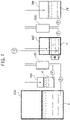
- the concentration system of FIG. 7 is another embodiment in which a membrane distillation method is applied as a second concentrating means, and is a system in which the second concentrating means is arranged after the first concentrating means.
- the feed solution (a) is concentrated by the forward osmotic membrane module (100) as the first concentrating means, and the feed solution (a) concentrated by the forward osmotic membrane module (100) is delivered to a product tank (600).
- the feed solution (a) concentrated by the first concentrating means is supplied at a suitable flow rate by a pump (P) from the bottom portion of the tank to one of the spaces of the membrane module (500) for membrane distillation, and concentration by the membrane distillation method is carried out.
- the feed solution (a) concentrated by the membrane module (500) for membrane distillation is returned to the product tank (600) to be circulated.
- a hydrometer (HM) and a level gauge (LG) are mounted to the product tank (600).
- the hydrometer (HM) can be used to compare the specific gravity to that of the desired water/organic solvent ratio.
- the level gauge (LG) can confirm whether the concentration has reached the target concentration rate or not.
- the concentration system of FIG. 8 is yet another embodiment in which a membrane distillation method is applied as a second concentrating means, and is a system in which the first concentrating means is arranged after the second concentrating means.
- the feed solution (a) is first sent to the membrane module (500) for membrane distillation and is concentrated by the membrane distillation method.
- the feed solution (a) after concentration is delivered to a product tank (600).
- the feed solution (a) after concentration is then sent from the product tank (600) to the forward osmotic membrane module (100), concentrated by the forward osmosis method, and thereafter returned to the product tank (600) to be circulated.
- the concentration by each of the membrane module (500) for membrane distillation and the forward osmotic membrane module (100) in the concentration system of FIG. 8 is similar to that shown in the concentration system of FIG. 7 .
- the feed solution (a) passes through the membrane module (500) for membrane distillation only once and is circulated in the forward osmotic membrane module (100), which differs from the system of FIG. 7 .
- a portion of the feed solution (a) from the membrane module (500) for membrane distillation may be sent to the product tank (600), with the remaining portion returned to the feed solution tank (200) to be circulation and concentrated.
- taking out the feed solution (a) from the bottom portion of the tank and returning it to the bottom portion of the tank are effective in preventing loss of the solute in the feed solution (a) adhering to the tank wall surface. It is also effective to provide the inner portion of the tank with a stirring function for stable concentration.
- the specific gravity of the feed solution (a) can be tracked with a hydrometer (HM).
- HM hydrometer
- the ratio of water and the organic solvent in the solvent of the feed solution (a) can be monitored. It is possible to carry out concentration while bringing the ratio of water and the organic solvent in the solvent (b) closer to the target value by suspending or slowing the operation of each concentration method as needed.
- the volume of the feed solution (a) can be measured with a level gauge (LG), and concentration can be completed when the target concentration rate is reached.
- LG level gauge
- pH and conductivity as items for monitoring the characteristics of the feed solution (a) can be used.
- concentration can be carried out while regulating the ratio of the organic solvent and water in the solvent (b) of the feed solution (a).
- a solute component in the feed solution precipitates during the process of concentrating the feed solution.
- the precipitate may obstruct the forward osmotic membrane, the membrane for membrane distillation, the piping system, etc. and hinder the concentration.
- a solid-liquid separation step of filtering the feed solution with a filter be carried out and only a liquid be supplied to the forward osmotic membrane module and the membrane module for membrane distillation.
- the filter can be arranged at any site, for example, in the feed solution tank, the outlet of the forward osmosis membrane module, the outlet of the membrane module for membrane distillation, or in the piping system.
- the material of the filter is not particularly limited to, for example, paper, a resin, a glass, or an inorganic substance, and may be appropriately selected from materials that are chemically and physically stable with respect to the feed solution.
- the opening of the filter may be appropriately set according to the size of the precipitate. From the viewpoint of preventing clogging, for example, a filter having an opening of 1 ⁇ m or greater is preferable.
- FIG. 9 is one example of a concentration system in which the feed solution tank (200) is provided with a filter (201).
- the filter (201) as a constituent element of the system in FIG. 9 , only the forward osmotic membrane module (100), the feed solution tank (200), the draw solution tank (300), and the piping system in the vicinity thereof are shown with the filter (201).
- an appropriate second concentration system such as a blower or a membrane module for membrane distillation, can be connected thereto to obtain the concentration system of the present invention.
- the concentration system of FIG. 9 is configured such that
- the flow rate for delivering the feed solution (a) is not particularly limited, but it is preferable that the flow rate be equal to or less than the supply flow rate of the feed solution in the forward osmotic membrane treatment used in the first concentration method.
- FIG. 10 is one example of a concentration apparatus in which the feed solution tank (200) is provided therein with a partition plate (201) and the inner portion of the feed solution tank (200) is divided into a first chamber (202) and a second chamber (203) by the partition plate (201).
- the concentration system of FIG. 10 is configured such that
- the feed solution (a) extracted from the bottom portion of the first chamber (202) of the feed solution tank (200) is supplied to the forward osmotic membrane module (100), which is the first concentrating unit, as illustrated in FIG. 10 .
- the feed solution (a) extracted from the bottom portion of the first chamber (202) may be supplied to an appropriate second concentrating unit, in place of the first concentrating unit or along with the first concentrating unit.
- the precipitate (a') settles at the bottom portion of the second chamber (203) due to the difference in specific gravity from the feed solution (a), and the portion near the liquid surface of the feed solution (a) in the second chamber (203) becomes a supernatant. Only the supernatant portion of the feed solution (a) is collected from one or more valves (in FIG. 10 ).
- the feed solution (a) from which the precipitate was removed can then be extracted from the bottom portion of the first chamber (202) and supplied to the first concentrating unit and/or the second concentrating unit for concentration to be carried out.
- the feed solution to be concentrated in the concentration method of the present invention is not particularly limited as long as the solution or the dispersion contains a solute and a solvent, and any solute and solution may be used.
- the forward osmotic membrane method and the membrane distillation method both are capable of concentrating without heating to, for example, 50 °C or higher, and are effectively applied to a feed solution where concentrating without heating is desirable.
- Examples of the applicable feed solution include foods, pharmaceuticals, seawater, and accompanying water discharged from gas fields and oil fields. Considering the advantage that concentrating without heating is possible, it is effective to apply the present invention to solutions or dispersions containing valuable substances that may be decomposed by heating, particularly drug feeds, drug substances, and drug intermediates (hereinafter, referred to as "pharmaceutical feed, etc.”), as solutes.
- a useful substance selected from the group consisting of an amino acid, a peptide, a protein, a saccharide, a vaccine, a nucleic acid, an antibiotic, an antibody-drug conjugate (ADC), and a vitamin is used as a solute. It is preferable that the solute be dissolved or diffused in a suitable solvent.
- the amino acid is a compound having one amino acid skeleton composed of a carboxyl group, an amino group, and a moiety connecting therebetween.
- the amino acid herein refers to a concept that encompasses essential amino acids, non-essential amino acids, and non-natural amino acids.
- Examples of the essential amino acid include tryptophan, lysine, methionine, phenylalanine, threonine, valine, leucine, and isoleucine.
- Examples of the non-essential amino acid include arginine, glycine, alanine, serine, tyrosine, cysteine, asparagine, glutamine, proline, aspartic acid, and glutamic acid.
- a non-natural amino acid refers to any artificial compound which has one amino acid skeleton in the molecule and does not exist in nature.
- examples of the non-natural amino acid as a solute of the pharmaceutical feed, etc. include ones obtained by a desired labeled compound to an amino acid skeleton.
- examples of the labeled compound include dyes, fluorescent substances, luminescent substances, enzyme substrates, coenzymes, antigenic substances, and protein-binding substances.
- non-natural amino acid as a solute of the pharmaceutical feed, etc. include labeled amino acids and functionalized amino acids.
- the labeled amino acid is a non-natural amino acid in which an amino acid skeleton and a labeled compound are bound. Specific examples thereof include an amino acid in which a labeled compound is bound to an amino acid skeleton including an aromatic ring in a side chain.
- Examples of the functionalized amino acid include photoresponsive amino acids, photoswitch amino acids, fluorescent probe amino acids, and fluorescent labeled amino acids.
- a peptide refers to a compound having 2 to less than 70 amino acid residues bound together, and may be linear or cyclic.
- Examples of a peptide to be concentrated include L-alanyl-L-glutamine, B-alanyl-L-histidine, cyclosporine, and glutathione.
- a protein generally refers to a compound having a longer chain than a peptide, among compounds having amino acid residues bound together.
- the protein herein is preferably one applicable as a protein formulation.
- Examples of the protein formulation include interferon ⁇ , interferon ⁇ , interleukins 1 to 12, growth hormone, erythropoietin, insulin, granulocyte colony-stimulating factor (G-CSF), tissue plasminogen activator (TPA), natriuretic peptide, blood coagulation factor VIII, somatomedin, glucagon, growth hormone-releasing factor, serum albumin, and calcitonin.
- G-CSF granulocyte colony-stimulating factor
- TPA tissue plasminogen activator
- natriuretic peptide natriuretic peptide
- blood coagulation factor VIII somatomedin
- glucagon growth hormone-releasing factor
- serum albumin serum albumin
- calcitonin calcitonin
- saccharide examples include monosaccharides, disaccharides, saccharide chains (excluding disaccharides), and saccharide chain derivatives.
- Examples of the monosaccharide include glycose, fructose, galactose, mannose, ribose, and deoxyribose.
- Examples of the disaccharide include maltose, sucrose, and lactose.
- the saccharide chain herein refers to a concept that excludes disaccharides, and examples thereof include glucose, galactose, mannose, fucose, xylose, glucuronic acid, and iduronic acid.
- Examples of the saccharide chain derivative include saccharide derivatives such as N-acetylglucosamine, N-acetylgalactosamine, and N-acetylneraminic acid.
- examples of the vaccine include hepatitis A vaccine, hepatitis B vaccine, and hepatitis C vaccine;
- examples of the nucleic acid include an oligonucleotide, RNA, an aptamer, and a decoy; and examples of the antibiotic include streptomycin and vancomycin.
- vitamin A examples include vitamin A, vitamin B, and vitamin C, and also include derivatives and salts thereof.
- Vitamin B encompasses, for example, vitamin B6 and vitamin B12.
- the number-average molecular weight of the solute contained in the feed solution may be about 100 to 50,000, preferably about 100 to 30,000, more preferably about 100 to 10,000, and particularly preferably 100 to 6,000.
- the solute When the molecular weight of the solute is excessively small, the solute may permeate through the forward osmotic membrane and the semi-permeable membrane during membrane distillation. When the molecular weight is excessively large, solute adhesion to a membrane surface may occur. Neither thereof is preferable.
- the number-average molecular weight of the solute can be obtained by calculation from the chemical formula of the solute.
- the molecular weight of the solute is comparatively large (for example, a molecular weight of 500 or greater)
- the number-average molecular weight can be obtained as a number-average molecular weight of a polyethylene glycol equivalent measured by GPC.
- the solvent of the feed solution is a liquid, and can be any inorganic solvent or organic solvent as long as the solute in the feed solution can be dissolved or diffused.
- the solvent of the feed solution of the present invention contains both water and an organic solvent.
- the organic solvent is preferably a solvent that is compatible with water, and may be, for example, an alcohol, a ketone, or an aprotic solvent.
- the solvent of the feed solution in the present invention is preferably a mixture of water and one or more selected from acetonitrile, isopropanol, acetone, methanol, and ethanol.
- the feed solution after concentration is subjected to specific gravity measurement, pH measurement, conductivity measurement, liquid level measurement, optical rotation measurement, near-infrared spectroscopic analysis, or weight measurement by online measurement.
- concentration can be carried out while estimating and adjusting the solute concentration and the solvent composition.
- the solute concentration can be found during the concentrating operation by the online measurement of the angle of optical rotation.
- Examples of the online measurement used for finding the solute concentration include specific gravity measurement, conductivity measurement, liquid level measurement, optical rotation measurement, and weight measurement.
- Examples of the online measurement used for finding the solvent concentration include specific gravity measurement, pH measurement, conductivity measurement, liquid level measurement, near-infrared spectroscopic analysis, and weight measurement.
- the concentration system of the present invention has a measuring means for measuring online at least one of the solute concentration and the solvent composition, preferably both thereof, and can adjust the solvent composition in accordance with a value measured by the measuring means.
- the deviation of the online measurement values from the target solute concentration and solvent composition is calculated; the operation, change in concentrating rate, or suspension of each of the first concentrating means and the second concentrating means is determined in accordance with the deviation; and adjustment is made to bring the solute concentration and solvent composition closer to the target solute concentration and solvent composition.
- the method of changing the concentrating rate include changing the concentrating temperature and changing the supply rate of the feed solution to each module.
- the component analysis of the final concentrated product (e) may be appropriately selected in accordance with the feed solution and the solute contained in the concentrate thereof.
- ICP-MS inductively coupled plasma mass spectrometry
- NMR nuclear magnetic resonance
- GC/MS gas chromatography-mass spectrometry
- HPLC high-performance liquid chromatography
- a concentration apparatus for a feed solution is provided.
- the concentration apparatus of the present invention may be any of the following: A concentration apparatus for concentrating a feed solution containing a solute and a solvent to obtain a concentrate of the feed solution, wherein
- the solvent composition of the feed solution in the feed solution tank be measured online and the operation or suspension of the first concentrating unit and the second concentrating unit be automatically determined in accordance with the measured solvent composition.
- a feature applicable to a concentration apparatus can be applied to the concentration apparatus of the present invention without limitation.
- a concentration method for a feed solution is provided.
- a concentration method for a feed solution comprising concentrating a feed solution containing a solute and a solvent to obtain a concentrate of the feed solution
- the concentration method for a feed solution can be carried out using, for example, the concentration system for a feed solution or the concentration apparatus for a feed solution of the present invention.
- a feature applicable to a concentration method can be applied to the concentration method in the present invention without limitation.
- a hollow-fiber support layer module having an effective intramembrane surface area of about 0.02 m 2 was produced by filling a cylindrical plastic housing having a diameter of 2 cm and a length of 10 cm with 130 hollow-fiber membrane ultrafiltration membranes having an inner diameter of 0.7 mm and an outer diameter of 1.0 mm and made of polyethersulfone as the substrate membrane and fixing both end portions thereof with an adhesive.
- the module production used a thermosetting epoxy resin as the adhesive resin to adhesively fix the hollow-fiber membrane to the housing interior by centrifugal adhesion. Subsequently, the hollow-fiber membrane was adjusted so that the length of the non-adhesively fixed portion was about 10 cm and the total membrane area of the inner surface of the hollow-fiber membrane was about 0.02 m 2 . Three membrane modules with these specifications were produced.
- FS-392B manufactured by Fluoro Technology was passed through the membrane module to a state of 3-fold concentration, applied to the outside of the hollow-fiber membrane, and dried, thereby obtaining a membrane module for membrane distillation.
- the membrane modules for membrane distillation obtained by the above method, one module was dissected to measure the characteristics of the porous hollow-fiber membrane.
- the water contact angle of the porous hollow-fiber membrane was calculated by dropping 2 ⁇ L of pure water under the conditions of a temperature of 23 °C and a relative humidity of 50% and analyzing the images of angles formed between the droplets and the outer surface of the hollow-fiber membrane to determine the contact angle. The measurement was carried out 5 times to calculate a numerical average.
- the contact angle of the outer surface of the hollow-fiber membrane was 132°, indicating very strong hydrophobicity.
- Example 1 concentration was carried out with a concentration apparatus 1 having the configuration shown in FIG. 5 .
- feed solution (a) 1 L of the feed solution (a) was charged in a feed solution tank (200) made of stainless steel.
- the feed solution (a) can be supplied to the forward osmotic membrane module (100) from the bottom portion of the feed solution tank (200), and piping is assembled so that the feed solution (a) concentrated by the forward osmotic membrane module (100) is returned to the bottom portion of the feed solution tank (200).
- the forward osmotic membrane module (100) mainly water of the solvent (b) in the feed solution (a) is transferred to the draw solution (d), and the feed solution (a) is concentrated.
- an air inlet through which air is introduced into the upper portion space of the tank by a blower (BL) and an outlet through which the solvent (b) (water and the organic solvent) vaporized by the air is discharged are provided. Subsequently, both water and the organic solvent of the solvent (b) in the feed solution (a) are removed, and the feed solution (a) is concentrated.
- the air and the solvent (b) discharged from the feed solution tank (200) are sent to a trap (400), and water and the organic solvent are recovered.
- a level gauge (LG) and a hydrometer (HM) are connected to the feed solution tank (200).
- the feed solution tank (200) is in a closed state.
- the tank is constructed such that the pressure of the inner portion of the tank is maintained at normal pressure even when the feed solution (a) is reduced.
- the piping system from the feed solution tank (200) to the forward osmotic membrane module (100) has a pump (P), a flow meter (not shown), and a valve (not shown) for regulating flow rate, and the flow rate can be appropriately controlled.
- a side pipe of the forward osmotic membrane module (100) is connected to an inlet pipe and an outlet pipe so that the draw solution (d) can be continuously supplied.
- the draw solution (d) is stored in the draw solution tank (300) and supplied to the forward osmotic membrane module (100) through the pump (P), the flow meter (not shown), and the valve (not shown) for regulating the flow rate.
- An aqueous solution of 25 wt% magnesium chloride was used as the draw solution (d).
- feed solution tank (200) made of stainless steel.
- the feed solution (a) can be supplied to each of the forward osmotic membrane module (100) and the membrane module (500) for membrane distillation from the bottom portion of the feed solution tank (200), and piping is assembled so that the feed solution (a) concentrated by each module is returned to the bottom portion of the feed solution tank (200).
- the feed solution tank (200) is in a closed state. However, the tank is constructed such that the pressure of the inner portion of the tank is maintained at normal pressure even when the feed solution (a) is reduced.
- a level gauge (LG) and a hydrometer (HM) are connected to the feed solution tank (200).
- the piping from the feed solution tank (200) to the forward osmotic membrane module (100) has a pump (P), a flow meter (not shown), and a valve (not shown) for regulating flow rate, and the flow rate can be appropriately controlled.
- a side pipe of the forward osmotic membrane module (100) is connected to an inlet pipe and an outlet pipe so that the draw solution (d) can be continuously supplied.
- the draw solution (d) is stored in the draw solution tank (300) and supplied to the forward osmotic membrane module (100) through the pump (P), the flow meter (not shown), and the valve (not shown) for regulating the flow rate.
- An aqueous solution of 25 wt% magnesium chloride was used as the draw solution (d).
- a pump (P), a flow meter (not shown), and a valve (not shown) for regulating the flow rate are arranged in the piping from the feed solution tank (200) to the membrane module (500) for membrane distillation.
- the feed solution (a) is supplied to the membrane module (500) for membrane distillation through a thermostat (not shown) for regulating the feed solution to a constant temperature and a heat exchanger (not shown).
- the concentrated feed solution (a) is then returned to the feed solution tank (200) from the outside of the membrane module (500) for membrane distillation.
- a side pipe of the membrane module (500) for membrane distillation is connected to an inlet pipe and an outlet pipe so that the cooling water (CW) can be continuously supplied.
- the cooling water (CW) is stored in a cooling water tank (700) and supplied to the membrane module (500) for membrane distillation through a pump (P), a flow meter (not shown), and a valve (not shown) for regulating flow rate.
- the cooling water (CW) is supplied to the membrane module (500) for membrane distillation through a thermostat (not shown) for regulating the cooling water (CW) to a constant temperature and a heat exchanger (not shown).
- the cooling water tank (700) is provided with an overflow and has a structure in which a portion of the increased portion of the cooling water (CW) is discharged to outside of the system.
- the specific gravity of the concentrated feed solution (a) is measured, operation is carried out according to the following criteria.
- the specific gravity of the concentrated feed solution (a) is measured, operation is carried out according to the following criteria.
- the concentration apparatus 1 was used in Example 1.
- This feed solution (a) and an aqueous solution having a 25 wt% concentration of magnesium chloride as the draw solution (d) were flowed into the forward osmotic membrane module (100).
- Air was continuously flowed into the upper portion space of the feed solution tank (200) at a flow rate of 10 L/min with a blower (BL).
- the target concentration rate was set to 10-fold or greater, and the ratio of the acetonitrile in the solvent (b) was set to 10% by volume.
- the concentration rate reached 10-fold or greater, and a concentrate having the ratio of the acetonitrile at 10% by volume was obtained.
- the temperature of the feed solution during the concentration was 27 to 30 °C.
- the concentration apparatus 2 was used in Example 2.
- the feed solution (a) and an aqueous solution having a 25 wt% concentration of magnesium chloride as the draw solution (d) were flowed into the forward osmotic membrane module (100).
- the feed solution (a) regulated to a temperature of 30 °C and cooling water (CW) regulated to a temperature of 10 °C were flowed into a membrane module (500) for membrane distillation, and concentration by both forward osmotic membrane method and membrane distillation method was carried out.
- the target concentration rate was set to 10-fold or greater, and the ratio of the acetonitrile in the solvent (b) was set to 10% by volume.
- the concentration rate reached 10-fold or greater, and a concentrate having the ratio of the acetonitrile in the solvent (b) at 10% by volume was obtained.
- the temperature of the feed solution during the concentration was 29 to 33 °C.
- the concentration apparatus 2 was used in Example 3.
- the feed solution (a) and an aqueous solution having a 25 wt% concentration of magnesium chloride as the draw solution (d) were flowed into the forward osmotic membrane module (100).
- the feed solution (a) regulated to a temperature of 30 °C and cooling water (CW) regulated to a temperature of 10 °C were flowed into a membrane module (500) for membrane distillation, and concentration by both forward osmotic membrane method and membrane distillation method was carried out.
- the target concentration rate was set to 10-fold or greater, and the ratio of the acetonitrile in the solvent (b) was set to 10% by volume.
- the concentration rate reached 10-fold or greater, and a concentrate having the ratio of the acetonitrile in the solvent (b) at 10% by volume was obtained.
- the temperature of the feed solution during the concentration was 27 to 32 °C.
- the magnesium chloride solution used for concentration and the cooling water were analyzed with the UV-visible spectrophotometer, the "insulin, human, recombinant" was not detected. Thus, it was determined that the concentration was carried out.
- the target concentration rate was set to 10-fold or greater, and the ratio of the acetonitrile in the solvent (b) was set to 50% by volume.
- the concentration rate reached 10-fold or greater, and a concentrate having the ratio of the acetonitrile in the solvent (b) at 50% by volume was obtained.
- the temperature of the feed solution during the concentration was 37 to 42 °C.
- the concentration apparatus 2 was used in Example 5.
- the feed solution (a) and an aqueous solution having a 50 wt% concentration of isopropanol as the draw solution (d) were flowed into the forward osmotic membrane module (100).
- the feed solution (a) regulated to a temperature of 30 °C and cooling water (CW) regulated to a temperature of 10 °C were flowed into a membrane module (500) for membrane distillation, and concentration by both forward osmotic membrane method and membrane distillation method was carried out.
- the target concentration rate was set to 10-fold or greater, the ratio of the acetonitrile in the solvent (b) was set to 10% by volume, and the ratio of the isopropanol in the solvent (b) was set to less than 5% by volume.
- the concentration rate reached 10-fold or greater, and a concentrate having the ratio of the acetonitrile in the solvent (b) at 10% by volume and the ratio of isopropanol in the solvent (b) of less than 1% by volume was obtained.
- the temperature of the feed solution during the concentration was 29 to 33 °C.
- the target concentration rate was set to 10-fold or greater, and the ratio of the isopropanol in the solvent (b) was set to 10% by volume.
- the concentration rate reached 10-fold or greater, and a concentrate having the ratio of the isopropanol in the solvent (b) at 10% by volume was obtained.
- the temperature of the feed solution during the concentration was 8 to 12 °C.
- the concentrating operation was initiated using only the forward osmotic membrane module (100) without using the membrane module (500) for membrane distillation and carried out in this state up to a concentration rate of 8-fold, and then the concentrating operation was continued using only the membrane module (500) for membrane distillation without using the forward osmotic membrane module (100) and carried out up to a concentrate rate of 10-fold, the concentrating operation was carried out in the same manner as in Example 2.
- the time required to concentrate the feed solution (a) up to 8-fold with the forward osmotic membrane module was 9 hours, and the time required to concentrate up to 10-fold with the membrane module for membrane distillation was 1 hour (for a total of 10 hours). It is considered that concentrating by the forward osmotic membrane module took time because the acetonitrile concentration in the solvent increased during concentration, and the rate of forward osmosis treatment by the forward osmotic membrane module slowed down.
- the ratio of the acetonitrile in the solvent was 21% by volume, which significantly changed from the starting composition.
- the ratio of the acetonitrile in the solvent (b) was 15% by volume.
- the concentrating operation was initiated using only the membrane module (500) for membrane distillation without using the forward osmotic membrane module (100) and carried out in this state up to a concentration rate of 8-fold, and then the concentrating operation was continued using only the forward osmotic membrane module (100) without using the membrane module (500) for membrane distillation and carried out up to a concentrate rate of 10-fold, the concentrating operation was carried out in the same manner as in Example 2.
- the total time required to concentrate the feed solution (a) 10-fold was 7 hours.
- the ratio of the acetonitrile in the solvent was 7.7% by volume.
- the ratio of the acetonitrile in the solvent was lower than that at starting.
- the ratio of the acetonitrile in the solvent (b) increased to 35% by volume, and a concentrate having the target composition could not be obtained.
- the temperature of the feed solution during the concentration was 25 to 27 °C.
- the ratio of the acetonitrile in the solvent (b) was less than 1% by volume at the stage in which the concentration rate was less than 10-fold, and the concentration was not able to reach the target rate.
- the temperature of the feed solution during concentration was 26 to 30 °C.
Landscapes
- Chemical & Material Sciences (AREA)
- Organic Chemistry (AREA)
- Engineering & Computer Science (AREA)
- Water Supply & Treatment (AREA)
- Chemical Kinetics & Catalysis (AREA)
- Life Sciences & Earth Sciences (AREA)
- Health & Medical Sciences (AREA)
- Proteomics, Peptides & Aminoacids (AREA)
- Molecular Biology (AREA)
- Biochemistry (AREA)
- Biophysics (AREA)
- General Health & Medical Sciences (AREA)
- Genetics & Genomics (AREA)
- Medicinal Chemistry (AREA)
- Analytical Chemistry (AREA)
- Environmental & Geological Engineering (AREA)
- Hydrology & Water Resources (AREA)
- Separation Using Semi-Permeable Membranes (AREA)
- Filtration Of Liquid (AREA)
- Diabetes (AREA)
- Endocrinology (AREA)
- Toxicology (AREA)
- Zoology (AREA)
- Gastroenterology & Hepatology (AREA)
Applications Claiming Priority (2)
| Application Number | Priority Date | Filing Date | Title |
|---|---|---|---|
| JP2019168623 | 2019-09-17 | ||
| PCT/JP2020/035322 WO2021054406A1 (ja) | 2019-09-17 | 2020-09-17 | 原料液濃縮方法および原料液濃縮システム |
Publications (2)
| Publication Number | Publication Date |
|---|---|
| EP4032601A4 EP4032601A4 (de) | 2022-07-27 |
| EP4032601A1 true EP4032601A1 (de) | 2022-07-27 |
Family
ID=74884305
Family Applications (1)
| Application Number | Title | Priority Date | Filing Date |
|---|---|---|---|
| EP20865822.9A Pending EP4032601A1 (de) | 2019-09-17 | 2020-09-17 | Verfahren zur konzentrierung von rohstofflösungen und system zur konzentrierung von rohstofflösungen |
Country Status (7)
| Country | Link |
|---|---|
| US (1) | US12576362B2 (de) |
| EP (1) | EP4032601A1 (de) |
| JP (1) | JP7249427B2 (de) |
| CN (1) | CN114302766B (de) |
| AU (1) | AU2020348086B2 (de) |
| CA (1) | CA3153382C (de) |
| WO (1) | WO2021054406A1 (de) |
Families Citing this family (4)
| Publication number | Priority date | Publication date | Assignee | Title |
|---|---|---|---|---|
| CN116710191A (zh) | 2021-01-15 | 2023-09-05 | 旭化成株式会社 | 有机原料液的脱水方法 |
| JP7735435B2 (ja) * | 2022-01-14 | 2025-09-08 | 旭化成株式会社 | 原料液の濃縮方法及び濃縮システム |
| WO2023249115A1 (ja) * | 2022-06-24 | 2023-12-28 | 旭化成株式会社 | 有機溶媒除去方法 |
| EP4545170A4 (de) * | 2022-06-24 | 2025-10-08 | Asahi Chemical Ind | Herstellungsverfahren und -programm, herstellungsvorrichtung, hilfsverfahren und -programm sowie hilfsvorrichtung |
Family Cites Families (26)
| Publication number | Priority date | Publication date | Assignee | Title |
|---|---|---|---|---|
| JPH1175759A (ja) | 1997-09-02 | 1999-03-23 | Sato Shokuhin Kogyo Kk | 粉末調味料の製造方法 |
| US8083942B2 (en) * | 2004-12-06 | 2011-12-27 | Board of Regents of the Nevada System of Higher Education, on Behalf of the Universary of Nevada, Reno | Systems and methods for purification of liquids |
| WO2007147013A1 (en) * | 2006-06-13 | 2007-12-21 | Board Of Regents Of The Nevada System Of Higher Education, On Behalf Of The University Of Nevada, Reno | Combined membrane-distillation-forward-osmosis systems and methods of use |
| JP2011525147A (ja) * | 2008-06-20 | 2011-09-15 | イェール ユニバーシティー | 正浸透分離法 |
| EA027334B1 (ru) | 2009-10-28 | 2017-07-31 | Оасис Уотер, Инк. | Способы прямого осмотического разделения |
| PE20142465A1 (es) | 2011-04-25 | 2015-01-22 | Oasys Water Inc | Sistemas y metodos de separacion osmotica |
| US20130048564A1 (en) | 2011-08-26 | 2013-02-28 | Battelle Energy Alliance, Llc | Draw solutes, methods of forming draw solutes, and methods of using draw solutes to treat an aqueous liquid |
| JP5537528B2 (ja) | 2011-09-28 | 2014-07-02 | 株式会社日立製作所 | 淡水精製装置 |
| BR112014028129A2 (pt) | 2012-05-14 | 2017-06-27 | Novo Nordisk As | soluções de proteína estabilizadas |
| CN103073146A (zh) * | 2013-02-06 | 2013-05-01 | 上海中科高等研究院 | 一种基于正渗透和膜蒸馏的废水处理方法及装置 |
| CA2900944A1 (en) | 2013-02-13 | 2014-08-21 | Oasys Water, Inc. | Renewable desalination of brines |
| WO2014163589A1 (en) | 2013-04-05 | 2014-10-09 | National University Of Singapore | Forward osmosis system using coordination complexes |
| JP6333573B2 (ja) | 2014-02-19 | 2018-05-30 | 株式会社ササクラ | 造水装置及び造水方法 |
| EP3167952B1 (de) | 2014-07-10 | 2022-05-11 | Asahi Kasei Kabushiki Kaisha | Membrandestillationsverfahren |
| JP6526440B2 (ja) * | 2015-02-24 | 2019-06-05 | 旭化成株式会社 | 正浸透処理システム |
| US10688439B2 (en) | 2015-02-26 | 2020-06-23 | King Abdullah University Of Science And Technology | Osmotically and thermally isolated forward osmosis-membrane distillation (FO-MD) integrated module for water treatment applications |
| KR102531484B1 (ko) * | 2015-06-24 | 2023-05-10 | 포리페라 인코포레이티드 | 정삼투를 통한 알콜성 용액의 탈수 방법 및 관련 시스템 |
| JP2017127842A (ja) | 2016-01-22 | 2017-07-27 | 株式会社東芝 | 水処理システムおよび水処理方法 |
| WO2017142494A1 (en) | 2016-02-15 | 2017-08-24 | Gebze Teknik Universitesi | A method for high volume recovery of process- water and economic product acquisition from whey |
| JP2018008270A (ja) | 2017-08-08 | 2018-01-18 | 三菱ケミカル株式会社 | 正浸透膜 |
| AU2018369298B2 (en) | 2017-11-20 | 2021-10-21 | Asahi Kasei Kabushiki Kaisha | System for concentrating solvent-containing articles, and concentrate |
| AU2018400230B2 (en) * | 2018-01-02 | 2024-06-13 | Botanical Water Technologies Ip Ltd | Isotopic compositions II |
| MX2020008774A (es) | 2018-02-22 | 2020-10-01 | Botanical Water Tech Ip Ltd | Sistemas y metodos para la preparacion de productos derivados de vegetales que utilizan tecnicas de osmosis. |
| CN108993146B (zh) | 2018-08-27 | 2021-03-26 | 天津工业大学 | 防腐剂作为汲取液的正渗透技术在产品浓缩方面的应用 |
| US20210339194A1 (en) * | 2018-09-03 | 2021-11-04 | Asahi Kasei Kabushiki Kaisha | Feedstock Solution Flow Concentration System |
| US20210198136A1 (en) | 2018-09-07 | 2021-07-01 | Jigar JANI | Combinatorial membrane-based systems and methods for dewatering and concentrating applications |
-
2020
- 2020-09-17 WO PCT/JP2020/035322 patent/WO2021054406A1/ja not_active Ceased
- 2020-09-17 EP EP20865822.9A patent/EP4032601A1/de active Pending
- 2020-09-17 US US17/641,207 patent/US12576362B2/en active Active
- 2020-09-17 JP JP2021546954A patent/JP7249427B2/ja active Active
- 2020-09-17 AU AU2020348086A patent/AU2020348086B2/en active Active
- 2020-09-17 CN CN202080060571.8A patent/CN114302766B/zh active Active
- 2020-09-17 CA CA3153382A patent/CA3153382C/en active Active
Also Published As
| Publication number | Publication date |
|---|---|
| JP7249427B2 (ja) | 2023-03-30 |
| WO2021054406A1 (ja) | 2021-03-25 |
| AU2020348086B2 (en) | 2023-07-27 |
| CA3153382A1 (en) | 2021-03-25 |
| US12576362B2 (en) | 2026-03-17 |
| EP4032601A4 (de) | 2022-07-27 |
| CA3153382C (en) | 2023-11-21 |
| AU2020348086A1 (en) | 2022-03-24 |
| US20240050897A1 (en) | 2024-02-15 |
| CN114302766A (zh) | 2022-04-08 |
| JPWO2021054406A1 (de) | 2021-03-25 |
| CN114302766B (zh) | 2024-12-06 |
Similar Documents
| Publication | Publication Date | Title |
|---|---|---|
| US12576362B2 (en) | Method for concentrating raw material solution, and system for concentrating raw material solution | |
| JP7555456B2 (ja) | 原料液濃縮システムおよび濃縮装置 | |
| JP7233530B2 (ja) | 原料液濃縮システム | |
| US20260115663A1 (en) | Raw Material Solution Concentration System | |
| JP7691506B2 (ja) | 正浸透膜を用いる分析溶液の濃縮方法、及び分析方法 | |
| JP2025026619A (ja) | 原料液減容方法及びシステム | |
| JP2024002708A (ja) | 組成推定方法 | |
| EP4691609A1 (de) | System zur konzentration eines rohstoffflüssigkeitsstroms und verfahren zur konzentration eines rohstoffflüssigkeitsstroms | |
| JP7735435B2 (ja) | 原料液の濃縮方法及び濃縮システム | |
| EP4545171A1 (de) | Verfahren zur entfernung von organischen lösungsmitteln | |
| JP2023092086A (ja) | 膜蒸留装置の運転方法 | |
| EP4691608A1 (de) | System zur dehydrierung eines rohstoffflüssigkeitsstroms und verfahren zur dehydrierung eines rohstoffflüssigkeitsstroms | |
| JP2024144379A (ja) | 原料液の濃縮方法及び濃縮システム | |
| JP2024160625A (ja) | 生体物質付着抑制能を有する限外ろ過膜 |
Legal Events
| Date | Code | Title | Description |
|---|---|---|---|
| STAA | Information on the status of an ep patent application or granted ep patent |
Free format text: STATUS: THE INTERNATIONAL PUBLICATION HAS BEEN MADE |
|
| PUAI | Public reference made under article 153(3) epc to a published international application that has entered the european phase |
Free format text: ORIGINAL CODE: 0009012 |
|
| STAA | Information on the status of an ep patent application or granted ep patent |
Free format text: STATUS: REQUEST FOR EXAMINATION WAS MADE |
|
| STAA | Information on the status of an ep patent application or granted ep patent |
Free format text: STATUS: EXAMINATION IS IN PROGRESS |
|
| 17P | Request for examination filed |
Effective date: 20220309 |
|
| A4 | Supplementary search report drawn up and despatched |
Effective date: 20220601 |
|
| AK | Designated contracting states |
Kind code of ref document: A1 Designated state(s): AL AT BE BG CH CY CZ DE DK EE ES FI FR GB GR HR HU IE IS IT LI LT LU LV MC MK MT NL NO PL PT RO RS SE SI SK SM TR |
|
| 17Q | First examination report despatched |
Effective date: 20220704 |
|
| DAV | Request for validation of the european patent (deleted) | ||
| DAX | Request for extension of the european patent (deleted) |