EP4032645A1 - Schrottschneider - Google Patents
Schrottschneider Download PDFInfo
- Publication number
- EP4032645A1 EP4032645A1 EP21204265.9A EP21204265A EP4032645A1 EP 4032645 A1 EP4032645 A1 EP 4032645A1 EP 21204265 A EP21204265 A EP 21204265A EP 4032645 A1 EP4032645 A1 EP 4032645A1
- Authority
- EP
- European Patent Office
- Prior art keywords
- blade
- cutter
- cutting
- scrap
- crankshaft
- Prior art date
- Legal status (The legal status is an assumption and is not a legal conclusion. Google has not performed a legal analysis and makes no representation as to the accuracy of the status listed.)
- Pending
Links
Images


Classifications
-
- B—PERFORMING OPERATIONS; TRANSPORTING
- B23—MACHINE TOOLS; METAL-WORKING NOT OTHERWISE PROVIDED FOR
- B23D—PLANING; SLOTTING; SHEARING; BROACHING; SAWING; FILING; SCRAPING; LIKE OPERATIONS FOR WORKING METAL BY REMOVING MATERIAL, NOT OTHERWISE PROVIDED FOR
- B23D15/00—Shearing machines or shearing devices cutting by blades which move parallel to themselves
- B23D15/04—Shearing machines or shearing devices cutting by blades which move parallel to themselves having only one moving blade
-
- B—PERFORMING OPERATIONS; TRANSPORTING
- B21—MECHANICAL METAL-WORKING WITHOUT ESSENTIALLY REMOVING MATERIAL; PUNCHING METAL
- B21D—WORKING OR PROCESSING OF SHEET METAL OR METAL TUBES, RODS OR PROFILES WITHOUT ESSENTIALLY REMOVING MATERIAL; PUNCHING METAL
- B21D43/00—Feeding, positioning or storing devices combined with, or arranged in, or specially adapted for use in connection with, apparatus for working or processing sheet metal, metal tubes or metal profiles; Associations therewith of cutting devices
- B21D43/28—Associations of cutting devices therewith
-
- B—PERFORMING OPERATIONS; TRANSPORTING
- B23—MACHINE TOOLS; METAL-WORKING NOT OTHERWISE PROVIDED FOR
- B23D—PLANING; SLOTTING; SHEARING; BROACHING; SAWING; FILING; SCRAPING; LIKE OPERATIONS FOR WORKING METAL BY REMOVING MATERIAL, NOT OTHERWISE PROVIDED FOR
- B23D15/00—Shearing machines or shearing devices cutting by blades which move parallel to themselves
- B23D15/06—Sheet shears
- B23D15/08—Sheet shears with a blade moved in one plane, e.g. perpendicular to the surface of the sheet
-
- B—PERFORMING OPERATIONS; TRANSPORTING
- B23—MACHINE TOOLS; METAL-WORKING NOT OTHERWISE PROVIDED FOR
- B23D—PLANING; SLOTTING; SHEARING; BROACHING; SAWING; FILING; SCRAPING; LIKE OPERATIONS FOR WORKING METAL BY REMOVING MATERIAL, NOT OTHERWISE PROVIDED FOR
- B23D15/00—Shearing machines or shearing devices cutting by blades which move parallel to themselves
- B23D15/12—Shearing machines or shearing devices cutting by blades which move parallel to themselves characterised by drives or gearings therefor
-
- B—PERFORMING OPERATIONS; TRANSPORTING
- B23—MACHINE TOOLS; METAL-WORKING NOT OTHERWISE PROVIDED FOR
- B23D—PLANING; SLOTTING; SHEARING; BROACHING; SAWING; FILING; SCRAPING; LIKE OPERATIONS FOR WORKING METAL BY REMOVING MATERIAL, NOT OTHERWISE PROVIDED FOR
- B23D35/00—Tools for shearing machines or shearing devices; Holders or chucks for shearing tools
- B23D35/001—Tools for shearing machines or shearing devices; Holders or chucks for shearing tools cutting members
-
- B—PERFORMING OPERATIONS; TRANSPORTING
- B23—MACHINE TOOLS; METAL-WORKING NOT OTHERWISE PROVIDED FOR
- B23P—METAL-WORKING NOT OTHERWISE PROVIDED FOR; COMBINED OPERATIONS; UNIVERSAL MACHINE TOOLS
- B23P23/00—Machines or arrangements of machines for performing specified combinations of different metal-working operations not covered by a single other subclass
- B23P23/04—Machines or arrangements of machines for performing specified combinations of different metal-working operations not covered by a single other subclass for both machining and other metal-working operations
-
- B—PERFORMING OPERATIONS; TRANSPORTING
- B23—MACHINE TOOLS; METAL-WORKING NOT OTHERWISE PROVIDED FOR
- B23D—PLANING; SLOTTING; SHEARING; BROACHING; SAWING; FILING; SCRAPING; LIKE OPERATIONS FOR WORKING METAL BY REMOVING MATERIAL, NOT OTHERWISE PROVIDED FOR
- B23D31/00—Shearing machines or shearing devices covered by none or more than one of the groups B23D15/00 - B23D29/00; Combinations of shearing machines
- B23D31/008—Cutting-up scrap
Definitions
- the present invention relates to a scrap cutter, and more particularly to a scrap cutter capable of cutting scrap material fed from a press machine with high efficiency and high speed.
- the types of scrap cutters include: a scrap cutter which cuts scrap materials between a fixed blade and a moving blade (cutter blade) which is reciprocated in the vertical direction by a crank mechanism or the like; and a scrap cutter having a structure in which a cutter blade is directly attached to a lower end of a connecting rod connected to a crankshaft and is pin-guided in the vertical direction toward the vicinity of the cutter part.
- some cutter blades have a shear angle of 0 degrees and other cutter blades have a certain shear angle.
- the shear angle is an angle formed by the moving blade and the fixed blade.
- Japanese Patent Application Laid-Open No. 2009-107096 proposes a cutting machine that drives a cutter blade by a link mechanism.
- the cutting machine is a cutting machine that cuts a thin work by causing a moving blade facing a fixed blade to cross the fixed blade.
- the cutting machine is configured as a four-link mechanism in which the moving blade (blade holder) is pivotally supported by two swing arms and suspended from a machine base. One of the two swing arms swings by a crank mechanism. The moving blade descends while swinging, and the moving blade diagonally crosses the fixed blade while gradually reducing the cutting angle (shear angle) of the moving blade, thereby sequentially performing pull-cut of the work from one end to the other end.
- Patent Literature 1 Japanese Patent Application Laid-Open No. 2009-107096
- the moving blade descends while being swung by the four-link mechanism so that the moving blade diagonally crosses the fixed blade while gradually reducing the cutting angle of the moving blade, thereby sequentially performing pull-cut of the work from one end to the other end.
- the blade holder including the moving blade swings left-right vibration is generated and the machine is not suitable for high speed operation.
- the cutting machine according to Japanese Patent Application Laid-Open No. 2009-107096 gradually reduces the cutting angle (shear angle) of the moving blade by swinging the moving blade at the time of cutting the work. As a result, it can eliminate or reduce breakage of the cut section of the work at the final stage of cutting to make the cut surface uniform and fine.
- the reason why the shear angle is gradually reduced is not in consideration of the press capacity at the time of cutting.
- the present invention has been made in view of such circumstances, and aims to provide a scrap cutter capable of cutting a scrap material fed from a press machine with high efficiency and high speed.
- an invention is a scrap cutter provided in a subsequent stage of a press machine and configured to cut a scrap material fed from the press machine, the scrap cutter including: a slide configured to be driven to reciprocate in the vertical direction by a crank mechanism; an upper blade attached to the slide; and a lower blade attached to a fixed part and configured to cut the scrap material in cooperation with the upper blade, wherein a shear angle formed by the upper blade and the lower blade has an angle which gradually decreases from a start of cutting of the scrap material toward an end of cutting of the scrap material, and allows a driving torque of a crankshaft of the crank mechanism to be constant from the start of cutting to the end of cutting in a case where a scrap material of a cutting capacity limit is cut.
- the shear angle has an angle which gradually decreases from the start of cutting the scrap material toward the end of cutting the scrap material, and allows the driving torque of the crankshaft of the crank mechanism that drives the slide having an upper blade attached thereto to reciprocate in the vertical direction to be constant, particularly in a case where the scrap material of the cutting capacity limit is cut. Therefore, it is possible to minimize the driving torque of the crankshaft in cutting the scrap material of the cutting capacity limit, minimize the inertia, stroke and vibration, and downsize the scrap cutter. As a result, the scrap material can be cut with high efficiency and high speed.
- the scrap material of the cutting capacity limit is determined by a thickness and a shear resistance of a material.
- the scrap cutter according to the present invention can naturally cut scrap materials within the cutting capacity limit with high efficiency and high speed.
- the upper blade and the lower blade form the above-described shear angle ⁇ .
- the crank mechanism is preferably a Scotch yoke mechanism.
- At least one of the upper blade and the lower blade is a cutter blade having an asymmetrically inclined blade that is asymmetric with respect to a center of the cutter blade, or a symmetrically inclined blade that is symmetrical with respect to the center of the cutter blade.
- the cutter blade may be an asymmetrically inclined blade (single-edged blade), or may be a symmetrically inclined blade (double-edged blade).
- the single-edged blade has an inclination angle different from that of the double-edged blade.
- the single-edged blade has the same height of the blade, as the double-edged blade.
- the shear angle formed by the upper blade and lower blade is optimized so that the scrap material fed from the press machine can be cut with high efficiency and high speed.
- Fig. 1 is a layout diagram of a press line including a scrap cutter according to the present invention.
- the press line shown in Fig. 1 includes an uncoiler 10, a leveler 20, a feeder 30, a press machine 40, a scrap cutter 50 and a waste material conveyor 60, which are sequentially arranged in this order.
- the uncoiler 10 is a material supply apparatus that unwinds a material wound around a drum in a coil shape (coil material) and supplies the unwound coil material while controlling the bending of the coil material.
- the leveler 20 is arranged between the uncoiler 10 and the feeder 30.
- the leveler 20 holds (sandwiches) the coil material between a plurality of alternately arranged rolls, and alternately deforms the coil material in the vertical direction to remove the strain from the coil material having curl.
- the feeder 30 is a material feeding apparatus that feeds the coil material into the die of the press machine 40 at regular intervals.
- the press machine 40 performs operation such as cutting-out the outer shapes of the products from the coil material.
- the scrap cutter 50 is provided in the subsequent stage of the press machine 40.
- the scrap cutter 50 cuts a scrap material (punching scrap of the coil material) fed from the press machine 40 into a size that is easy to handle, and discharges the cut scrap material to the waste material conveyor 60.
- the scrap cutter 50 of the example is operated in synchronization with the press machine 40.
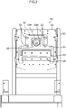
- Fig. 2 is a front view of the scrap cutter 50.
- the scrap cutter 50 includes: a frame 52 that functions as a fixed part fixed by a column 51; a slide 54 that is guided by a guide 53 so as to be movable in the vertical direction in the frame 52; an upper blade (moving blade) 55 attached to the slide 54; a lower blade (fixed blade) 56 attached to the frame 52; and a Scotch yoke mechanism 57 which is a type of crank mechanism that drives the slide 54 to reciprocate in the vertical direction.
- the Scotch yoke mechanism 57 includes: a slider 58; and a crankshaft 59.
- the slide 58 is provided so as to be movable in the left-right direction, in a rectangular opening 54A formed in the slide 54.
- the left-right direction is a direction orthogonal to the vertical direction
- the vertical direction is the moving direction of the slide 54.
- rotational driving force is transmitted from a servomotor (not shown), and an eccentric part 59A of the crankshaft 59 is rotatably inserted into the slider 58 via a bearing.
- the Scotch yoke mechanism 57 is used as the crank mechanism, the motion of the upper blade 55, which is the moving blade, turns into a sine motion.
- the driving force is transmitted only in the vertical direction to the slide 54 to which the upper blade 55 is attached, it is possible to suppress the left-right vibration.
- the scrap material fed from the press machine 40 is set between the upper blade 55 and the lower blade 56 of the scrap cutter 50 during a period when there is a gap between the upper blade 55 and the lower blade 56 (for example, the period in the range of ⁇ 90 degrees where 0 degree represents the rotation angle of the crankshaft 59 when the slide 54 is located at the top dead center), and then, the scrap material is cut with the descending upper blade 55 which works in cooperation with the lower blade 56.
- the blade shape of cutter blade which is at least one of the upper blade 55 and the lower blade 56.
- the blade shape of the cutter blade described below is for the blade shape of the upper blade 55.
- the scrap cutter 50 cuts various scrap materials having various materials, plate thicknesses, and the like.
- the scrap cutter according to the present example has a shear angle formed by the upper blade 55 and the lower blade 56 designed as shown below so as to highly efficiently cut a scrap material of an allowable limit of the cutting capacity (a scrap material of a cutting capacity limit).
- the shear angle formed by the upper blade 55 and the lower blade 56 is applied to the scrap cutter 50.
- the shear angle gradually decreases from a start of cutting of the scrap material toward an end of cutting so as to allow the driving torque of the crankshaft of the crank mechanism to be constant from the start of cutting to the end of cutting in a case where the scrap material of the cutting capacity limit is cut.
- Fig. 3 is a diagram illustrating a pushing force applied to the cutter blade by the driving torque of the crankshaft.
- Figs. 4A and 4B are diagrams showing types of the blade shapes of the cutter blade.
- the cutter blade shown in Fig. 4A is an asymmetrically inclined blade that is bilaterally asymmetrical with respect to the center of the cutter blade, and is a single-edged blade that cuts from one end toward the other end of the scrap material at the time of cutting the scrap material.
- the cutter blade shown in Fig. 4B is a symmetrically inclined blade that is bilaterally symmetrical with respect to the center of the cutter blade, and is a double-edged blade that cuts from both ends of the scrap material toward the center of the scrap material at the time of cutting the scrap material.
- Fig. 5 is a diagram showing a relationship between a position of the double-edged cutter blade (upper blade) and the rotation angle of the crankshaft, and Part (A) to Part (E) show the respective positions of the upper blade from the start of cutting to the end of cutting of the scrap material.
- Part (A) shows the position of the upper blade 55 when the rotation angle of the crankshaft is an angle ⁇ a.
- the position of the upper blade 55 shown in Part (A) is the position when the upper blade 55 first comes into contact with the scrap material 70 after the upper blade 55 descends as the crankshaft rotates. Cutting of the scrap material 70 starts from this position of the upper blade 55.
- Part (C) shows the position of the upper blade 55 when the rotation angle of the crankshaft is an angle ⁇ c.
- the position of the upper blade 55 shown in Part (C) indicates the position when the uppermost point of the upper blade 55 (center of the upper blade 55) reaches the upper surface of the scrap material 70 after the upper blade 55 further descends.
- Part (B) shows the position of the upper blade 55 when the rotation angle of the crankshaft is between the angle ⁇ a and the angle ⁇ c, where a part of the upper blade 55 reaches the lower surface of the scrap material 70.
- the reference signs 70A and 70B designate shear surfaces that can be sheared by the pushing force applied to the upper blade 55 at this position.
- the stroke length k of the upper blade 55 from the position shown in Part (A) to the position shown in Part (C) (from the crankshaft angle ⁇ a to the crankshaft angle ⁇ c) is equal to a gap k created by the shear angle of the upper blade 55 between the uppermost point of the upper blade 55 and the upper surface of the scrap material 70 when the upper blade 55 is in the position shown in Part (A).
- Part (E) shows the position of the upper blade 55 when the rotation angle of the crankshaft reaches the angle ⁇ e (the slide 54 is at the bottom dead center).
- the stroke length of the upper blade 55 from the position shown in Part (C) to the position shown in Part (E) is the same as the plate thickness t of the scrap material 70.
- Part (D) shows the position of the upper blade 55 when the rotation angle of the crankshaft is between the angle ⁇ c and the angle ⁇ e.
- Fig. 6 is a diagram illustrating the relationship between the pushing force applied to the cutter blade and the shear area of the scrap material that can be sheared by the pushing force.
- the upper blade 55 which is a moving blade
- the lower blade 56 which is a fixed blade
- the upper blade 55 moves in the vertical direction.
- the inclination angle of the cutter blade corresponds to the shear angle.
- the shear angle ⁇ indicated in [Expression 3] is an angle that gradually decreases from the start of cutting of the scrap material toward the end of cutting (with the rotation angle ⁇ of the crankshaft being a variable).
- this shear angle ⁇ is an angle at which the scrap material can be cut with a constant driving torque T of the crankshaft (in a state where the maximum torque is output) from the start of cutting to the end of cutting, in cutting the scrap material of the cutting capacity limit which is determined by the plate thickness t and shear resistance Kfc.
- the scrap cutter 50 having the above configuration can reduce the crankshaft driving torque T (rated torque of the servomotor that drives the crankshaft) required for cutting the scrap material of the cutting capacity limit.
- the scrap cutter 50 can reduce the inertia of the part including the slide 54 and the upper blade 55, that reciprocates in the vertical direction. Therefore, it is possible to cut the scrap material fed from the press machine with high efficiency and high speed.
- the blade shape of the cutter blade which has an inclination corresponding to the shear angle ⁇ shown in [Expression 3] is defined in a two-dimensional coordinate.
- the blade shape of the cutter blade is defined in an xy coordinate system in which the x-axis direction represents the longitudinal direction of the cutter blade and the y-axis direction represents the moving direction of the cutter blade.
- the x coordinate on the cutting edge of the cutter blade can be expressed by the following expression.
- Figs. 7A and 7B illustrate graphs showing examples of blade shapes of the cutter blades.
- the blade shape of the cutter blade can be calculated, for example, by appropriately giving constants and the variable h in [Expression 11]. The details are to be described below.
- Fig. 7A shows a blade shape in a case where the cutter blade is a single-edged blade
- Fig. 7B shows a blade shape in a case where the cutter blade is a double-edged blade.
- the heights of the cutter blades are the same in both the single-edged blade and the double-edged blade.
- the inclination angle corresponding to the shear angle ⁇ is greater in the double-edged blade than in the single-edged blade.
- the driving torque T of the crankshaft 70 [Nm]
- crank radius r 12.5 [mm]
- the plate thickness t of the scrap material 0.3 [mm]
- n 2 (1 for the single-edged blade, 2 for the double-edged blade)
- the cutting start height h1 6 [mm]
- Figs. 8 and 9 are charts showing the calculation results of xy coordinates and the corresponding values of the respective cutter blades.
- Y coordinates are obtained for 51 points on the cutting edge of the cutter blade in a case where the height of the cutter blade (difference between the cutting start height and the cutting end height) is divided into 50 equal parts.
- X coordinates corresponding to each of the y coordinates can be obtained by calculation.
- Fig. 8 shows the calculation results of xy coordinates for points 0 to 25 of the 51 points on the cutting edge of the cutter blade
- Fig. 9 shows the calculation results of xy coordinates for the other points 26 to 50.
- Figs. 8 and 9 show the rotation angles ⁇ [rad] and ⁇ [deg] of the crankshaft and the shear angles ⁇ [rad] and ⁇ [deg], each corresponding to the points 0 to 50, in addition to the xy coordinates of the points 0 to 50.
- Fig. 10 is a graph showing the blade shape of the cutter blade, which is created by plotting the xy coordinates at the points 0 to 50 on the cutting edge of the cutter blade shown in Figs. 8 and 9 .
- a continuously changing inclination is provided to the upper blade (moving blade) without providing an inclination to the lower blade (fixed blade), so as to continuously change the shear angle ⁇ formed by the fixed blade and the moving blade from the start of cutting of the scrap material to the end of cutting.
- a continuously changing inclination may be provided to the fixed blade without providing an inclination to the moving blade, so as to continuously change the shear angle ⁇ formed by the fixed blade and the moving blade from the start of cutting of the scrap material to the end of cutting.
- the Scotch yoke mechanism is used as the crank mechanism for driving the upper blade (moving blade) to reciprocate in the vertical direction, but the present invention is not limited to this configuration.
- a slide-crank mechanism in which the eccentric part of the crankshaft is connected to the slide with a connecting rod, may be applied.
- the conrod stroke ratio (connecting rod length/crank radius) of the slide-crank mechanism is large to some extent, the movement of the slide becomes substantially sinusoidal motion, so that the calculation expression used in the Scotch yoke mechanism can be used as it is. Note that a large conrod stroke ratio is suitable for high speed operation.
Landscapes
- Engineering & Computer Science (AREA)
- Mechanical Engineering (AREA)
- Physics & Mathematics (AREA)
- Optics & Photonics (AREA)
- Shearing Machines (AREA)
- Accessories And Tools For Shearing Machines (AREA)
Applications Claiming Priority (1)
| Application Number | Priority Date | Filing Date | Title |
|---|---|---|---|
| JP2020177866A JP7381431B2 (ja) | 2020-10-23 | 2020-10-23 | スクラップカッター |
Publications (1)
| Publication Number | Publication Date |
|---|---|
| EP4032645A1 true EP4032645A1 (de) | 2022-07-27 |
Family
ID=78695443
Family Applications (1)
| Application Number | Title | Priority Date | Filing Date |
|---|---|---|---|
| EP21204265.9A Pending EP4032645A1 (de) | 2020-10-23 | 2021-10-22 | Schrottschneider |
Country Status (4)
| Country | Link |
|---|---|
| US (1) | US20220126382A1 (de) |
| EP (1) | EP4032645A1 (de) |
| JP (1) | JP7381431B2 (de) |
| CN (1) | CN114473004B (de) |
Families Citing this family (1)
| Publication number | Priority date | Publication date | Assignee | Title |
|---|---|---|---|---|
| WO2023204254A1 (ja) | 2022-04-19 | 2023-10-26 | 株式会社小松製作所 | 林業機械および監視システム |
Citations (2)
| Publication number | Priority date | Publication date | Assignee | Title |
|---|---|---|---|---|
| AT372029B (de) * | 1981-07-10 | 1983-08-25 | Voest Alpine Ag | Schere zum querteilen langgestreckten gutes |
| JP2009107096A (ja) | 2007-10-31 | 2009-05-21 | Isel Co Ltd | 切断機 |
Family Cites Families (38)
| Publication number | Priority date | Publication date | Assignee | Title |
|---|---|---|---|---|
| US2047322A (en) * | 1933-05-26 | 1936-07-14 | Cincinnati Shaper Co | Shears for sheet metal |
| DE1527007B1 (de) * | 1963-12-05 | 1970-10-22 | Moeller & Neumann Gmbh | Blechschere mit einem geraden und einem gebogenen Messer |
| GB1439464A (en) * | 1972-09-09 | 1976-06-16 | Handley A R | Shear cutter |
| US3941021A (en) * | 1975-01-17 | 1976-03-02 | Meinholdt John W | Shearing apparatus |
| DE2611988A1 (de) * | 1976-03-20 | 1977-09-29 | Schloemann Siemag Ag | Fliegende querteilschere fuer bleche |
| AU2961277A (en) * | 1976-10-18 | 1979-04-26 | Davy Loewy Ltd | Rolling cut shear |
| FR2409812A1 (fr) * | 1977-11-26 | 1979-06-22 | Behrens Ag C | Presse a decouper pour le travail de pieces en forme de plaques, en particulier de toles |
| EP0055063B1 (de) * | 1980-12-23 | 1985-10-30 | DAVY McKEE (SHEFFIELD) LIMITED | Schere |
| IT1190865B (it) * | 1982-06-09 | 1988-02-24 | Salvagnini Transferica Spa | Cesoia per lamiera con lame a squadra a segmenti reciprocamente spostabili |
| US5090285A (en) * | 1987-12-14 | 1992-02-25 | Hitachi Metals, Ltd. | Sheet cutter |
| US4981058A (en) * | 1988-09-14 | 1991-01-01 | Lear Siegler, Inc. | Punch and die set and method adapted to effect parting between adjacent sections of a workpiece |
| JPH05261615A (ja) * | 1992-03-18 | 1993-10-12 | Aida Eng Ltd | スクラップカッター装置 |
| IL105743A0 (en) * | 1992-06-11 | 1993-09-22 | Dov Shilkrut | Penetrating tool system |
| US5458057A (en) * | 1992-12-21 | 1995-10-17 | Arens; Cornelius G. | Apparatus for facilitating the installation of a dieset in a reciprocating press |
| JP2611128B2 (ja) * | 1993-08-17 | 1997-05-21 | 株式会社アマダメトレックス | 追切り用切断金型 |
| US5832611A (en) * | 1996-08-07 | 1998-11-10 | Schmitz; Jeffrey F. | Variable angle reciprocating tool |
| US5737989A (en) * | 1996-12-26 | 1998-04-14 | Sung; Huang Ming | Hydraulic paper cutting machine |
| JP3711734B2 (ja) * | 1998-02-25 | 2005-11-02 | セイコーエプソン株式会社 | カッタ装置及びこれを用いたプリンタ |
| DE50100423D1 (de) * | 2001-12-06 | 2003-08-28 | Trumpf Werkzeugmaschinen Gmbh | Verfahren und Maschine zum mehrhubig fortschreitenden Schlitzen von plattenartigen Werkstücken, insbesondere von Blechen |
| JP2005111624A (ja) * | 2003-10-09 | 2005-04-28 | Konica Minolta Medical & Graphic Inc | 走行切断機 |
| DE502005009241D1 (de) * | 2004-08-24 | 2010-04-29 | Soudronic Ag Bergdietikon | Schlagschere für bleche |
| EP2004342B1 (de) * | 2006-04-07 | 2014-10-15 | Wilson Tool International Inc. | Multiwerkzeug-technologie |
| JP4658851B2 (ja) | 2006-04-12 | 2011-03-23 | 株式会社大阪チタニウムテクノロジーズ | スポンジチタン用切断機及びこれに使用される切断刃 |
| JP5042936B2 (ja) * | 2007-07-30 | 2012-10-03 | 新日本製鐵株式会社 | シャー角付き打ち抜きせん断装置 |
| JP5239276B2 (ja) | 2007-09-20 | 2013-07-17 | Jfeスチール株式会社 | ダウンカット式クロップシャーおよび上刃材ならびに上刃材の刃先形状の決定方法および上刃材の製造方法 |
| JP5339515B2 (ja) | 2009-02-09 | 2013-11-13 | 株式会社ケイエステック | 棒材切断機 |
| JP2010247278A (ja) | 2009-04-16 | 2010-11-04 | Nippon Steel Corp | シャー切断制御方法 |
| US20110005360A1 (en) * | 2009-07-08 | 2011-01-13 | Marcus Gordon Birch | Root cutting tool |
| JP2012000727A (ja) * | 2010-06-17 | 2012-01-05 | Nissan Motor Co Ltd | ワーク切断装置及びワーク切断装置の切断刃清掃方法 |
| JP5982970B2 (ja) * | 2011-06-28 | 2016-08-31 | 村田機械株式会社 | パンチプレスの追い抜き金型および板材の長孔形成方法 |
| CN102445291B (zh) * | 2011-09-26 | 2013-09-11 | 浙江工业大学 | 应用于多层鞋革数控裁割机床裁割皮革所需吸附力的测量方法 |
| GB2504344B (en) * | 2012-07-27 | 2014-08-27 | Siemens Plc | Variable rake shear |
| GB2514774B (en) * | 2013-06-03 | 2016-02-24 | Primetals Technologies Ltd | A shear |
| CN203371114U (zh) * | 2013-07-24 | 2014-01-01 | 中冶赛迪工程技术股份有限公司 | 用于剪切宽窄钢板的剪刃 |
| JP2015174161A (ja) * | 2014-03-13 | 2015-10-05 | 富士通コンポーネント株式会社 | カット装置、プリンタ装置及びカット装置の制御方法 |
| CN104227122A (zh) * | 2014-07-04 | 2014-12-24 | 太原科技大学 | 一种长尺寸金属板材纵向精密滚动剪切机 |
| CN109843465B (zh) * | 2016-09-26 | 2020-12-18 | 通快机床两合公司 | 用于板状工件的多冲程进展式切槽的方法、机床和切槽工具 |
| US11498345B2 (en) * | 2019-07-30 | 2022-11-15 | Brother Kogyo Kabushiki Kaisha | Cutter unit including fixed blade and movable blade to cut item in cooperation with each other |
-
2020
- 2020-10-23 JP JP2020177866A patent/JP7381431B2/ja active Active
-
2021
- 2021-10-14 US US17/501,964 patent/US20220126382A1/en not_active Abandoned
- 2021-10-20 CN CN202111224126.3A patent/CN114473004B/zh active Active
- 2021-10-22 EP EP21204265.9A patent/EP4032645A1/de active Pending
Patent Citations (2)
| Publication number | Priority date | Publication date | Assignee | Title |
|---|---|---|---|---|
| AT372029B (de) * | 1981-07-10 | 1983-08-25 | Voest Alpine Ag | Schere zum querteilen langgestreckten gutes |
| JP2009107096A (ja) | 2007-10-31 | 2009-05-21 | Isel Co Ltd | 切断機 |
Also Published As
| Publication number | Publication date |
|---|---|
| CN114473004A (zh) | 2022-05-13 |
| CN114473004B (zh) | 2025-12-09 |
| JP7381431B2 (ja) | 2023-11-15 |
| US20220126382A1 (en) | 2022-04-28 |
| JP2022068988A (ja) | 2022-05-11 |
Similar Documents
| Publication | Publication Date | Title |
|---|---|---|
| EP2891530B1 (de) | Verfahren und vorrichtung zum beschneiden eines viereckigen behältnisses | |
| EP4032645A1 (de) | Schrottschneider | |
| CN1235786C (zh) | 材料条带穿孔的方法和装置 | |
| US4079649A (en) | Rolling cut type double side shear | |
| EP2540428A1 (de) | Nibbelanordnung für eine Lochpresse und Verfahren zur Herstellung eines Längslochs in bahnförmigem Material | |
| CN107052130B (zh) | 弯折上料机构及其上料方法 | |
| CN102873392A (zh) | 一种金属厚板带精整剪切用飞剪装置 | |
| US3426635A (en) | Arrangement in sheet metal working machines,particularly nibbling machines | |
| KR20130020694A (ko) | 후판의 트리밍 방법 및 장치 | |
| EP3231566A1 (de) | Schneidvorrichtung und verfahren zum betrieb davon | |
| CN1273252C (zh) | 全自动在线液压钢坯斜剪机 | |
| EP4523869A1 (de) | Querschneidevorrichtung, beutelherstellungsmaschine und querschneideverfahren | |
| CN217070914U (zh) | 一种剪切机的动刀架及剪切机 | |
| US20050103171A1 (en) | Methods and apparatus for cutting a moving material | |
| CA1233355A (en) | Method and apparatus for producing lids with tear tabs | |
| CN212093910U (zh) | 一种具有梳齿结构的工件的冲裁设备 | |
| CN104260947B (zh) | 用于泡罩包装机的多组连杆横向成型冲裁机构及操作方法 | |
| US20230023673A1 (en) | Plate material cutting device | |
| US4852440A (en) | Flying shear or stamping apparatus for strip material | |
| US20060048557A1 (en) | Method and device for bending blade member | |
| CN101073814A (zh) | 形成波形平板的方法和模具以及由此形成的波形平板 | |
| CN221454494U (zh) | 龙门剪切机用刀架及龙门剪切机 | |
| CN204223312U (zh) | 用于泡罩包装机的多组连杆横向成型冲裁机构 | |
| CN219336176U (zh) | 一种龙门式剪切设备 | |
| CN213469751U (zh) | 一种伺服薄板剪板机 |
Legal Events
| Date | Code | Title | Description |
|---|---|---|---|
| PUAI | Public reference made under article 153(3) epc to a published international application that has entered the european phase |
Free format text: ORIGINAL CODE: 0009012 |
|
| STAA | Information on the status of an ep patent application or granted ep patent |
Free format text: STATUS: THE APPLICATION HAS BEEN PUBLISHED |
|
| AK | Designated contracting states |
Kind code of ref document: A1 Designated state(s): AL AT BE BG CH CY CZ DE DK EE ES FI FR GB GR HR HU IE IS IT LI LT LU LV MC MK MT NL NO PL PT RO RS SE SI SK SM TR |
|
| STAA | Information on the status of an ep patent application or granted ep patent |
Free format text: STATUS: REQUEST FOR EXAMINATION WAS MADE |
|
| 17P | Request for examination filed |
Effective date: 20230126 |
|
| RBV | Designated contracting states (corrected) |
Designated state(s): AL AT BE BG CH CY CZ DE DK EE ES FI FR GB GR HR HU IE IS IT LI LT LU LV MC MK MT NL NO PL PT RO RS SE SI SK SM TR |