EP4032655B1 - Verfahren zum prüfen von schweissfehlern - Google Patents
Verfahren zum prüfen von schweissfehlern Download PDFInfo
- Publication number
- EP4032655B1 EP4032655B1 EP20921672.0A EP20921672A EP4032655B1 EP 4032655 B1 EP4032655 B1 EP 4032655B1 EP 20921672 A EP20921672 A EP 20921672A EP 4032655 B1 EP4032655 B1 EP 4032655B1
- Authority
- EP
- European Patent Office
- Prior art keywords
- resistance
- welded portion
- measuring
- threshold
- welding
- Prior art date
- Legal status (The legal status is an assumption and is not a legal conclusion. Google has not performed a legal analysis and makes no representation as to the accuracy of the status listed.)
- Active
Links
Images





Classifications
-
- G—PHYSICS
- G01—MEASURING; TESTING
- G01N—INVESTIGATING OR ANALYSING MATERIALS BY DETERMINING THEIR CHEMICAL OR PHYSICAL PROPERTIES
- G01N27/00—Investigating or analysing materials by the use of electric, electrochemical, or magnetic means
- G01N27/02—Investigating or analysing materials by the use of electric, electrochemical, or magnetic means by investigating impedance
- G01N27/04—Investigating or analysing materials by the use of electric, electrochemical, or magnetic means by investigating impedance by investigating resistance
- G01N27/041—Investigating or analysing materials by the use of electric, electrochemical, or magnetic means by investigating impedance by investigating resistance of a solid body
-
- B—PERFORMING OPERATIONS; TRANSPORTING
- B23—MACHINE TOOLS; METAL-WORKING NOT OTHERWISE PROVIDED FOR
- B23K—SOLDERING OR UNSOLDERING; WELDING; CLADDING OR PLATING BY SOLDERING OR WELDING; CUTTING BY APPLYING HEAT LOCALLY, e.g. FLAME CUTTING; WORKING BY LASER BEAM
- B23K26/00—Working by laser beam, e.g. welding, cutting or boring
- B23K26/20—Bonding
- B23K26/21—Bonding by welding
-
- B—PERFORMING OPERATIONS; TRANSPORTING
- B23—MACHINE TOOLS; METAL-WORKING NOT OTHERWISE PROVIDED FOR
- B23K—SOLDERING OR UNSOLDERING; WELDING; CLADDING OR PLATING BY SOLDERING OR WELDING; CUTTING BY APPLYING HEAT LOCALLY, e.g. FLAME CUTTING; WORKING BY LASER BEAM
- B23K31/00—Processes relevant to this subclass, specially adapted for particular articles or purposes, but not covered by any single one of main groups B23K1/00 - B23K28/00
- B23K31/12—Processes relevant to this subclass, specially adapted for particular articles or purposes, but not covered by any single one of main groups B23K1/00 - B23K28/00 relating to investigating the properties, e.g. the weldability, of materials
- B23K31/125—Weld quality monitoring
-
- G—PHYSICS
- G01—MEASURING; TESTING
- G01N—INVESTIGATING OR ANALYSING MATERIALS BY DETERMINING THEIR CHEMICAL OR PHYSICAL PROPERTIES
- G01N27/00—Investigating or analysing materials by the use of electric, electrochemical, or magnetic means
- G01N27/02—Investigating or analysing materials by the use of electric, electrochemical, or magnetic means by investigating impedance
- G01N27/04—Investigating or analysing materials by the use of electric, electrochemical, or magnetic means by investigating impedance by investigating resistance
- G01N27/20—Investigating the presence of flaws
-
- G—PHYSICS
- G01—MEASURING; TESTING
- G01N—INVESTIGATING OR ANALYSING MATERIALS BY DETERMINING THEIR CHEMICAL OR PHYSICAL PROPERTIES
- G01N33/00—Investigating or analysing materials by specific methods not covered by groups G01N1/00 - G01N31/00
- G01N33/20—Metals
- G01N33/207—Welded or soldered joints; Solderability
-
- H—ELECTRICITY
- H01—ELECTRIC ELEMENTS
- H01M—PROCESSES OR MEANS, e.g. BATTERIES, FOR THE DIRECT CONVERSION OF CHEMICAL ENERGY INTO ELECTRICAL ENERGY
- H01M10/00—Secondary cells; Manufacture thereof
- H01M10/42—Methods or arrangements for servicing or maintenance of secondary cells or secondary half-cells
- H01M10/48—Accumulators combined with arrangements for measuring, testing or indicating the condition of cells, e.g. the level or density of the electrolyte
-
- H—ELECTRICITY
- H01—ELECTRIC ELEMENTS
- H01M—PROCESSES OR MEANS, e.g. BATTERIES, FOR THE DIRECT CONVERSION OF CHEMICAL ENERGY INTO ELECTRICAL ENERGY
- H01M50/00—Constructional details or processes of manufacture of the non-active parts of electrochemical cells other than fuel cells, e.g. hybrid cells
- H01M50/50—Current conducting connections for cells or batteries
- H01M50/531—Electrode connections inside a battery casing
-
- H—ELECTRICITY
- H01—ELECTRIC ELEMENTS
- H01M—PROCESSES OR MEANS, e.g. BATTERIES, FOR THE DIRECT CONVERSION OF CHEMICAL ENERGY INTO ELECTRICAL ENERGY
- H01M50/00—Constructional details or processes of manufacture of the non-active parts of electrochemical cells other than fuel cells, e.g. hybrid cells
- H01M50/50—Current conducting connections for cells or batteries
- H01M50/531—Electrode connections inside a battery casing
- H01M50/536—Electrode connections inside a battery casing characterised by the method of fixing the leads to the electrodes, e.g. by welding
-
- B—PERFORMING OPERATIONS; TRANSPORTING
- B23—MACHINE TOOLS; METAL-WORKING NOT OTHERWISE PROVIDED FOR
- B23K—SOLDERING OR UNSOLDERING; WELDING; CLADDING OR PLATING BY SOLDERING OR WELDING; CUTTING BY APPLYING HEAT LOCALLY, e.g. FLAME CUTTING; WORKING BY LASER BEAM
- B23K2101/00—Articles made by soldering, welding or cutting
- B23K2101/36—Electric or electronic devices
- B23K2101/38—Conductors
-
- Y—GENERAL TAGGING OF NEW TECHNOLOGICAL DEVELOPMENTS; GENERAL TAGGING OF CROSS-SECTIONAL TECHNOLOGIES SPANNING OVER SEVERAL SECTIONS OF THE IPC; TECHNICAL SUBJECTS COVERED BY FORMER USPC CROSS-REFERENCE ART COLLECTIONS [XRACs] AND DIGESTS
- Y02—TECHNOLOGIES OR APPLICATIONS FOR MITIGATION OR ADAPTATION AGAINST CLIMATE CHANGE
- Y02E—REDUCTION OF GREENHOUSE GAS [GHG] EMISSIONS, RELATED TO ENERGY GENERATION, TRANSMISSION OR DISTRIBUTION
- Y02E60/00—Enabling technologies; Technologies with a potential or indirect contribution to GHG emissions mitigation
- Y02E60/10—Energy storage using batteries
-
- Y—GENERAL TAGGING OF NEW TECHNOLOGICAL DEVELOPMENTS; GENERAL TAGGING OF CROSS-SECTIONAL TECHNOLOGIES SPANNING OVER SEVERAL SECTIONS OF THE IPC; TECHNICAL SUBJECTS COVERED BY FORMER USPC CROSS-REFERENCE ART COLLECTIONS [XRACs] AND DIGESTS
- Y02—TECHNOLOGIES OR APPLICATIONS FOR MITIGATION OR ADAPTATION AGAINST CLIMATE CHANGE
- Y02P—CLIMATE CHANGE MITIGATION TECHNOLOGIES IN THE PRODUCTION OR PROCESSING OF GOODS
- Y02P70/00—Climate change mitigation technologies in the production process for final industrial or consumer products
- Y02P70/50—Manufacturing or production processes characterised by the final manufactured product
Definitions
- the present invention relates to a method for inspecting a welding defect, and more particularly, to a method for inspecting whether there is a welding defect by a weak welding on the welded portion between an electrode tab and an electrode tab or between an electrode tab and an electrode lead in a lithium secondary battery.
- a secondary battery unlike a primary battery that cannot be charged, means a battery that can be charged and discharged, and is widely used in electronic devices such as mobile phones, notebook computers, camcorders, or electric vehicles.
- the lithium secondary battery has a larger capacity than a nickel-cadmium battery or a nickelhydrogen battery, and because the energy density per unit weight is high, the degree of utilization thereof is rapidly increasing.
- lithium secondary batteries are classified according to the structure of the electrode assembly having a positive electrode/separator/negative electrode structure.
- Representative examples thereof include a j elly-roll electrode assembly in which long sheet type positive electrodes and negative electrodes are wound with a separator interposed therebetween, a stacked electrode assembly in which a plurality of positive and negative electrodes cut in a predetermined size unit are sequentially stacked with a separator interposed therebetween, and a stacked/foldable electrode assembly in which bi-cells or full cells, in which positive and negative electrodes of a predetermined unit are stacked with a separator interposed therebetween, are wound.
- a pouch type battery having a stack type or stack/folding type electrode assembly embedded in a pouch-shaped battery case of an aluminum laminate sheet has attracted a lot of attention due to its low manufacturing cost and small weight, and the amount used thereof is gradually increasing.
- the lithium secondary battery mainly uses a lithium-based oxide and a carbon material as a positive electrode active material and a negative electrode active material, respectively.
- the lithium secondary battery includes an electrode assembly, in which a positive electrode plate and a negative electrode plate coated with the positive electrode active material and the negative electrode active material, respectively, are disposed with a separator interposed therebetween, and an exterior material that seals and stores the electrode assembly together with the electrolyte.
- a plurality of positive electrode tabs which are extended from a plurality of positive electrode plates, and a plurality of negative electrode tabs, which are extended from a plurality of negative electrode plates, are formed in the electrode assembly, and the plurality of positive electrode tabs and the plurality of negative electrode tabs are respectively coupled with the positive electrode lead and the negative electrode lead by welding.
- a plurality of positive electrode tabs and a plurality of negative electrode tabs form an electrode tab
- a positive electrode lead and a negative electrode lead form an electrode lead.
- Korean Patent 2017-0125707 discloses a technology of dividing a welded portion, which is generated by coupling electrode foil elements and terminals, into a plurality of sections, measuring the resistance for each section by applying electric current to each section, and then determining that there is a welding defect if the measured resistance is greater than a threshold resistance.
- the correlation between the tensile strength and the resistance in the welded portion is used in deriving the threshold resistance, and thus in order to derive the threshold resistance, a process of measuring the tensile strength of the welded portion is essential.
- CN 103 376 788 B relates to a method for detecting lithium ion battery tab welding firmness.
- CN 108 181 356 A relates to the field of battery measurement.
- CN 107 607 592 A relates to welding spot quality detection, in particular to a welding reliability testing method and equipment.
- the tensile strength of the welded portion is measured by pulling the welded portion in an opposite direction, which may cause an error.
- the reliability of the threshold resistance value derived from the correlation between the tensile strength and the resistance is not high.
- an object of the present invention is to provide a method for inspecting a weak welding of a welded portion with excellent detection power while allowing complete enumeration.
- the resistance measuring probe includes a voltage probe and a current probe.
- the resistance measuring step (S200) includes measuring a resistance of a welded portion by a 4-wire type measuring scheme.
- the resistance measuring step (S200) includes measuring a resistance of a welded portion by a direct current scheme.
- the threshold resistance setting step (S 100) includes: a data construction step (S 110) of measuring a microresistance of nanoohm and microohm units for a sample group and storing the measured microresistance; and a threshold resistance value deriving step (S120) of deriving a threshold value by processing data accumulated by the data construction step (S 110) by a statistical scheme.
- a number of objects of the sample group is equal to or greater than 100,000.
- resistance values of the sample group form a normal distribution curve.
- the threshold resistance value is an average value + 6 ⁇ .
- the welded portion is formed by a ultrasonic welding. At this time, the resistance is measured by allowing the resistance measuring probe to contact an interface of the welded portion.
- the welded portion is formed by a laser welding. At this time, the resistance is measured by allowing the resistance measuring probe to contact an outer peripheral surface of the welded portion.
- the method for inspecting a welding defect of the present invention is preferably applied to a welded portion between an electrode lead and an electrode tab of a pouch-type secondary battery, or a welded portion between an electrode tab and an electrode tab.
- resistances of a sample group are measured, a threshold resistance value is set from a normal distribution curve of the measured resistance values, and resistances are precisely measured by using a microresistance measuring instrument having a resolution of nanoohm to microohm levels when measuring resistances for the sample group and the welded portion to be inspected, thereby showing an excellent detection power for a weak welding defect.
- FIG. 1 is a flowchart of a method for inspecting a welding defect according to the present invention.
- a method for inspecting a welding defect of the present invention includes: a threshold resistance setting step (S100) of measuring a resistance of a welded portion of a sample group and deriving a threshold resistance value which becomes an evaluation standard of a weak welding; a resistance measuring step (S200) of measuring a resistance value of a welded portion to be inspected; and a determination step (S300) of determining the welded portion as a weak welding if the resistance value measured in the resistance measuring step exceeds the threshold resistance value, wherein the threshold resistance setting step (S 100) and the resistance measuring step (S200) include measuring a resistance using a microresistance measuring instrument having a resolution of nanoohm to microohm units.
- the inventors of the present invention have found that the electric resistance value of the welded portion having a low welding strength was greater than the electric resistance value of the welded portion having a normal welding strength, which has led them to the present invention.
- a resistance value of a welded portion having been welded by a normal welding strength of 22 kgf or more is smaller than a resistance value of a welded portion having been welded by a weak welding strength less than 22 kgf.
- the method of deriving the threshold resistance value was not specific, or a process of measuring the tensile strength of the welded portion was necessary because the correlation between the tensile strength of the welded portion and the resistance was used when deriving the threshold resistance value.
- the present invention is characterized in introducing a statistical scheme in deriving a threshold resistance value while not relying on a correlation between a tensile strength and a resistance of a welded portion and in precisely measuring a resistance by measuring the resistance up to nanoohm to microohm levels by increasing the resolution.
- the measured resistance values form a normal distribution curve.
- an object having a large deviation may be easily assumed as being defective from a standpoint of a statistical probability, and thus a predetermined deviation is determined as a threshold resistance value.
- this approach is based on a premise that data for the sample group are reliable.
- a microresistance measuring instrument capable of precisely measuring the resistance up to nanoohm to microohm levels for the sample group is used in the process of setting a threshold value, and a microresistance measuring instrument capable of precisely measuring the resistance up to nanoohm to microohm levels is used when measuring the resistance for the object to be inspected.
- a threshold resistance value is statistically derived from a large amount of sample groups when deriving the threshold resistance value. Hence, it is not necessary to separately measure the tensile strength of the welded portion in order to set the threshold resistance value unlike the conventional technology.
- the threshold resistance setting step (5100) includes: a data construction step (S 110) of measuring a microresistance of nanoohm and microohm units for a sample group and storing the measured microresistance; and a threshold resistance value deriving step (S120) of deriving a threshold value by processing data accumulated by the data construction step (S 110) by a statistical scheme.
- the data construction step (S110) includes a process of measuring the resistance of a welded portion for objects which form a sample group. At this time, the number of objects of the sample group is at least 100,000, preferably 200,000, and it is preferable to have as many objects of the sample group as possible in terms of reliability.
- the data construction step (S110) resistances for objects of the sample group are measured by using a microresistance measuring instrument having a resolution of nanoohm (n ⁇ ) to microohm (u ⁇ ) units. This is to accumulate more reliable data. Further, the microresistance measuring method is performed in the same manner as that of the scheme of measuring the resistance of the welded portion in the resistance measuring step (S200).
- the threshold resistance value deriving step (S 120) includes deriving a threshold resistance value by processing data accumulated by the data construction step (S 110) by a statistical scheme.
- the statistical processing method according to an embodiment of the present invention is to obtain a normal distribution curve of the resistance value of an object of the sample group and to the + 6 ⁇ value in the normal distribution curve as the threshold resistance value.
- FIG. 3 shows an example of a distribution curve of resistances of a sample group according to an embodiment of the present invention.
- the majority of objects have values close to the average value ( ⁇ ), and the number of objects having a value, which is significantly deviated from the average value ( ⁇ ), is small. Therefore, objects having a value, which is significantly deviated from the average value, may be stochastically assumed as being defective.
- the probability that an object having a deviation of 16 (standard deviation) appears is about 32%
- the probability that an object having a deviation of 2 ⁇ appears is about 5%
- the probability that an object having a deviation of 3 ⁇ appears is about 0.3%
- the probability that an object having a deviation of 4 ⁇ appears is about 0.01%
- the probability that an object having a deviation of 56 appears is about 0.001%
- the probability that an object having a deviation of 6 ⁇ appears is about 0.0000001%.
- the sum of the average value and 6 ⁇ was set as the threshold resistance value.
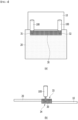
- FIG. 4 is a schematic diagram showing a method of measuring a resistance according to an embodiment of the present invention.
- a microresistance measuring instrument which is used for resistance measurement in the resistance measuring step (S200) of the present invention, includes two resistance measuring probes 100, and resistances are measured by allowing the two resistance measuring probes to contact the welded portion 30.
- the resistance of the entire welded portion 30 is measured by allowing one resistance measuring probe to contact one end 31 of the welded portion and allowing the other resistance measuring probe to contact the other end of the welded portion.
- the welded portion 30 can be divided into a welded portion 33 of the electrode tab 20 portion and a welded portion 34 of the electrode lead 10, and as illustrated in FIG. 4(b) , both of the two resistance measuring probes can be allowed to contact the welded portion 33 of the electrode tab 20. Unlike this, both of the two resistance measuring probes may be allowed to contact the welded portion 34 of the electrode lead 10.
- one resistance measuring probe may be allowed to contact the welded portion 33 of the electrode tab 20, and the remaining one resistance measuring probe may be allowed to contact the welded portion 34 of the electrode lead 10, to thereby measure the resistance.
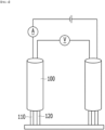
- FIG. 6 shows a schematic diagram of a resistance measuring probe of the present invention
- the resistance measuring probe 100 of the present invention includes a current probe 110 and a voltage probe 120.
- the current probe applies current to a welded portion to be measured, and the voltage probe measures voltages. As such, the resistance of the welded portion can be measured.
- the resistance is measured by allowing two resistance measuring probes to contact the welded portion.
- the resistance of the welded portion can be measured by a 4-wire type measuring scheme. Since the 4-wire type resistance measuring scheme is less influenced by the contact resistance compared to the 2-wire type resistance measuring scheme, the microresistance can be more precisely measured in the 4-wire type resistance measuring scheme, in which the resistance can be measured even in nanoohm units.
- the resistance measuring step (S200) includes measuring a resistance of a welded portion by a direct current scheme.
- the direct current scheme has an advantage that high-precision resistance measurement is possible, compared to the alternating current scheme.
- the welding defect inspection method of the present invention can be widely applied to the welded portion of the secondary battery and can be applied to the welded portion according to various welding schemes. Namely, the welding defect inspection method of the present invention can be applied to a welded portion between an electrode tab and an electrode tab, a welded portion between an electrode tab and an electrode lead, and a welded portion between an electrode lead and a bus bar in a battery pack, and may also be applied to a welded portion by ultrasonic welding and a welded portion by laser welding, etc.
- FIG. 7 is a schematic diagram showing a method of measuring a resistance to a welded portion according to an ultrasonic welding scheme.
- a welded portion 30 formed by the ultrasonic welding scheme has the form of a line or a surface.
- the contact position 40 of the resistance measuring probe for resistance measurement is positioned on the boundary line of the welded portion.
- the resistance of the entire welded portion can be measured by allowing the resistance measuring probe to contact the boundary line of the welded portion.
- the current probe contacts two of the contact positions 40, and the voltage probe contacts the remaining two of the contact positions 40.
- FIG. 8 is a schematic diagram showing a method of measuring a resistance to a welding portion according to a laser welding scheme.
- the welded portion 30 formed by the laser welding scheme has a dotted shape.
- the current probe contacts two of the contact positions 40
- the voltage probe contacts the remaining two of the contact positions 40.
- resistances of a sample group are measured, a threshold resistance value is set from a normal distribution curve of the measured resistance values, and resistances are precisely measured by using a microresistance measuring instrument having a resolution of nanoohm to microohm levels when measuring resistances for the sample group and the welded portion to be inspected, thereby showing an excellent detection power for a weak welding defect.
Landscapes
- Chemical & Material Sciences (AREA)
- Engineering & Computer Science (AREA)
- Chemical Kinetics & Catalysis (AREA)
- Electrochemistry (AREA)
- Physics & Mathematics (AREA)
- Life Sciences & Earth Sciences (AREA)
- Health & Medical Sciences (AREA)
- General Chemical & Material Sciences (AREA)
- General Physics & Mathematics (AREA)
- Analytical Chemistry (AREA)
- Pathology (AREA)
- Immunology (AREA)
- General Health & Medical Sciences (AREA)
- Biochemistry (AREA)
- Mechanical Engineering (AREA)
- Quality & Reliability (AREA)
- Optics & Photonics (AREA)
- Manufacturing & Machinery (AREA)
- Medicinal Chemistry (AREA)
- Food Science & Technology (AREA)
- Plasma & Fusion (AREA)
- Investigating Or Analyzing Materials By The Use Of Electric Means (AREA)
- Connection Of Batteries Or Terminals (AREA)
- Measurement Of Resistance Or Impedance (AREA)
Claims (13)
- Verfahren zum Prüfen eines Schweißfehlers, umfassend:einen Schwellenwiderstandseinstellschritt (S100) des Messens eines Widerstands eines Schweißabschnitts einer Probengruppe und des Ableitens eines Schwellenwiderstandswerts, der ein Bewertungsstandard für ein schwaches Schweißen wird;einen Widerstandsmessschritt (S200) des Messens eines Widerstandswerts eines zu prüfenden Schweißabschnitts, wobei der zu prüfende Schweißabschnitt der gesamte Schweißabschnitt ist; undeinen Bestimmungsschritt (S300) des Bestimmens des Schweißabschnitts als schwaches Schweißen, wenn der im Widerstandsmessschritt gemessene Widerstandswert den Schwellenwiderstandswert überschreitet,wobei der Schwellenwiderstandseinstellschritt (S100) und der Widerstandsmessschritt (S200) das Messen eines Widerstands unter Verwendung eines Mikrowiderstandsmessinstruments mit einer Auflösung von Nanoohm- zu Mikroohm-Einheiten umfassen,dadurch gekennzeichnet, dassder Widerstandsmessschritt (S200) das Messen eines Widerstands durch Ermöglichen, dass zwei Widerstandsmesssonden den Schweißabschnitt berühren, und das Messen eines Gesamtwiderstands des Schweißabschnitts durch Ermöglichen, dass eine Widerstandsmesssonde ein Ende des Schweißabschnitts berührt, und Ermöglichen, dass eine andere Widerstandsmesssonde ein anderes Ende des Schweißabschnitts berührt, umfasst.
- Verfahren nach Anspruch 1, wobei die Widerstandsmesssonde eine Spannungssonde und eine Stromsonde umfasst.
- Verfahren nach Anspruch 1, wobei der Widerstandsmessschritt (S200) das Messen eines Widerstands des Schweißabschnitts durch ein 4-Draht-Messschema umfasst.
- Verfahren nach Anspruch 1, wobei der Widerstandsmessschritt (S200) das Messen eines Widerstands des Schweißabschnitts durch ein Gleichstromschema umfasst.
- Verfahren nach Anspruch 1, wobei der Schwellenwiderstandseinstellschritt (S100) umfasst:einen Datenkonstruktionsschritt (S110) des Messens eines Mikrowiderstands von Nanoohm- und Mikroohm-Einheiten für die Probengruppe und des Speicherns des gemessenen Mikrowiderstands; undeinen Schwellenwiderstandswertableitungsschritt (S120) des Ableitens des Schwellenwiderstandswerts durch Verarbeiten von durch den Datenkonstruktionsschritt (S110) gesammelten Daten durch ein statistisches Schema.
- Verfahren nach Anspruch 5, wobei eine Anzahl von Objekten der Probengruppe gleich oder größer als 100.000 ist.
- Verfahren nach Anspruch 5, wobei Widerstandswerte der Probengruppe eine Normalverteilungskurve bilden.
- Verfahren nach Anspruch 7, wobei der Schwellenwiderstandswert ein Mittelwert + 6δ ist.
- Verfahren nach Anspruch 1, wobei der Schweißabschnitt durch Ultraschallschweißen gebildet wird.
- Verfahren nach Anspruch 9, wobei der Widerstand durch Ermöglichen, dass die Widerstandsmesssonde eine Grenzlinie des Schweißabschnitts berührt, gemessen wird.
- Verfahren nach Anspruch 1, wobei der Schweißabschnitt durch Laserschweißen gebildet wird.
- Verfahren nach Anspruch 11, wobei der Widerstand durch Ermöglichen, dass die Widerstandsmesssonde eine Außenumfangsfläche des Schweißabschnitts berührt, gemessen wird.
- Verfahren nach Anspruch 1, wobei der Schweißabschnitt einer ist, der aus einem Schweißabschnitt zwischen einer Elektrodenleitung und einer Elektrodenlasche einer beutelartigen Sekundärbatterie und einem Schweißabschnitt zwischen einer Elektrodenlasche und einer Elektrodenlasche einer beutelartigen Sekundärbatterie ausgewählt ist.
Applications Claiming Priority (2)
| Application Number | Priority Date | Filing Date | Title |
|---|---|---|---|
| KR1020200023657A KR102772444B1 (ko) | 2020-02-26 | 2020-02-26 | 용접 불량 검사 방법 |
| PCT/KR2020/019247 WO2021172728A1 (ko) | 2020-02-26 | 2020-12-29 | 용접 불량 검사 방법 |
Publications (3)
| Publication Number | Publication Date |
|---|---|
| EP4032655A1 EP4032655A1 (de) | 2022-07-27 |
| EP4032655A4 EP4032655A4 (de) | 2022-12-07 |
| EP4032655B1 true EP4032655B1 (de) | 2024-09-11 |
Family
ID=77491292
Family Applications (1)
| Application Number | Title | Priority Date | Filing Date |
|---|---|---|---|
| EP20921672.0A Active EP4032655B1 (de) | 2020-02-26 | 2020-12-29 | Verfahren zum prüfen von schweissfehlern |
Country Status (9)
| Country | Link |
|---|---|
| US (1) | US12025578B2 (de) |
| EP (1) | EP4032655B1 (de) |
| JP (1) | JP7479465B2 (de) |
| KR (1) | KR102772444B1 (de) |
| CN (1) | CN114616462B (de) |
| ES (1) | ES2996905T3 (de) |
| HU (1) | HUE068983T2 (de) |
| PL (1) | PL4032655T3 (de) |
| WO (1) | WO2021172728A1 (de) |
Families Citing this family (2)
| Publication number | Priority date | Publication date | Assignee | Title |
|---|---|---|---|---|
| CN119846494A (zh) * | 2023-10-18 | 2025-04-18 | 宁德时代新能源科技股份有限公司 | 电池汇流排测试装置、方法、系统、电子设备及介质 |
| KR20260011368A (ko) | 2024-07-16 | 2026-01-23 | 주식회사 엘지에너지솔루션 | 레이저 용접 장치 및 방법 |
Citations (2)
| Publication number | Priority date | Publication date | Assignee | Title |
|---|---|---|---|---|
| US20170322168A1 (en) * | 2016-05-06 | 2017-11-09 | GM Global Technology Operations LLC | Method and apparatus for evaluating a weld junction between a terminal and an electrode element of a battery cell |
| KR101887148B1 (ko) * | 2017-12-22 | 2018-08-09 | 조태문 | 용접품질 검사 시스템 및 장치 |
Family Cites Families (21)
| Publication number | Priority date | Publication date | Assignee | Title |
|---|---|---|---|---|
| JP2000100465A (ja) | 1998-09-25 | 2000-04-07 | Fuji Photo Film Co Ltd | 電池の検査装置及び検査方法 |
| JP4330690B2 (ja) | 1999-03-16 | 2009-09-16 | パナソニック株式会社 | 2次電池の溶接不良の検出方法 |
| US6265688B1 (en) * | 2000-02-03 | 2001-07-24 | Norman A. Lyshkow | Method of welding metals and apparatus for use therefor |
| JP4474808B2 (ja) * | 2001-06-28 | 2010-06-09 | 株式会社デンソー | 溶接部の非破壊検査方法および溶接部の非破壊検査装置 |
| US7988745B2 (en) | 2006-02-07 | 2011-08-02 | Gs Yuasa International Ltd. | Method for manufacturing battery, battery manufactured by the method, and method for inspecting battery |
| KR100886572B1 (ko) | 2006-02-13 | 2009-03-05 | 주식회사 엘지화학 | 중대형 전지모듈에서 단위전지들의 용접 상태를 검사하는방법 |
| BRPI0818126A2 (pt) * | 2007-11-02 | 2020-10-06 | Nippon Steel Corporation | sistema e método para monitoramento de estado de soldagem |
| JP5127788B2 (ja) * | 2009-08-01 | 2013-01-23 | 株式会社豊田中央研究所 | 抵抗溶接方法、抵抗溶接部材、抵抗溶接機、抵抗溶接機の制御方法とその制御プログラムおよびその制御装置並びに抵抗溶接の評価方法とその評価プログラムおよびその評価装置 |
| US8421472B2 (en) * | 2010-03-11 | 2013-04-16 | Toyota Motor Engineering & Manufacturing North America, Inc. | Apparatuses and methods for testing welding apparatuses |
| JP2012200765A (ja) * | 2011-03-25 | 2012-10-22 | Toyota Motor Corp | 抵抗溶接の品質評価方法及び装置 |
| US9421634B2 (en) * | 2011-11-09 | 2016-08-23 | Fca Us Llc | System and method for performing resistance spot welding |
| KR101487577B1 (ko) * | 2012-02-02 | 2015-01-29 | 주식회사 엘지화학 | 배터리 팩의 고장 진단 방법 및 장치, 이를 이용한 전력 릴레이 어셈블리 |
| KR20130097990A (ko) | 2012-02-27 | 2013-09-04 | 조선대학교산학협력단 | 이차전지 극주탭 t형상 용접 방법 |
| CN103376278B (zh) * | 2012-04-27 | 2016-03-16 | 协鑫动力新材料(盐城)有限公司 | 一种检测锂离子电池极耳焊接牢固度的方法 |
| KR20140141289A (ko) | 2013-05-31 | 2014-12-10 | 주식회사 엘지화학 | 셀의 전극탭 용접불량 선별방법 |
| US9843002B2 (en) | 2015-10-29 | 2017-12-12 | Semiconductor Energy Laboratory Co., Ltd. | Organometallic complex, light-emitting element, light-emitting device, electronic device, and lighting device |
| CN107607592A (zh) | 2017-10-10 | 2018-01-19 | 深圳军洋科技发展有限公司 | 焊接可靠性测试方法及设备 |
| CN108181356A (zh) | 2018-01-11 | 2018-06-19 | 哈尔滨理工大学 | 一种电池焊接质量的测量方法 |
| KR102057781B1 (ko) * | 2018-06-25 | 2019-12-19 | 현대제철 주식회사 | 스폿용접부의 품질 예측 장치와 방법 |
| KR102173204B1 (ko) | 2018-08-13 | 2020-11-03 | 고려대학교 산학협력단 | 빅데이터 시각화 기반의 특허 분석 시스템 및 그 방법 |
| US11906593B2 (en) * | 2019-10-31 | 2024-02-20 | Keysight Technologies, Inc. | Method and system for testing the structural integrity of a metal joint |
-
2020
- 2020-02-26 KR KR1020200023657A patent/KR102772444B1/ko active Active
- 2020-12-29 EP EP20921672.0A patent/EP4032655B1/de active Active
- 2020-12-29 CN CN202080075215.3A patent/CN114616462B/zh active Active
- 2020-12-29 JP JP2022524016A patent/JP7479465B2/ja active Active
- 2020-12-29 HU HUE20921672A patent/HUE068983T2/hu unknown
- 2020-12-29 US US17/771,163 patent/US12025578B2/en active Active
- 2020-12-29 WO PCT/KR2020/019247 patent/WO2021172728A1/ko not_active Ceased
- 2020-12-29 PL PL20921672.0T patent/PL4032655T3/pl unknown
- 2020-12-29 ES ES20921672T patent/ES2996905T3/es active Active
Patent Citations (2)
| Publication number | Priority date | Publication date | Assignee | Title |
|---|---|---|---|---|
| US20170322168A1 (en) * | 2016-05-06 | 2017-11-09 | GM Global Technology Operations LLC | Method and apparatus for evaluating a weld junction between a terminal and an electrode element of a battery cell |
| KR101887148B1 (ko) * | 2017-12-22 | 2018-08-09 | 조태문 | 용접품질 검사 시스템 및 장치 |
Also Published As
| Publication number | Publication date |
|---|---|
| EP4032655A1 (de) | 2022-07-27 |
| KR20210108716A (ko) | 2021-09-03 |
| JP2023500225A (ja) | 2023-01-05 |
| ES2996905T3 (en) | 2025-02-13 |
| CN114616462B (zh) | 2025-07-01 |
| HUE068983T2 (hu) | 2025-02-28 |
| US12025578B2 (en) | 2024-07-02 |
| KR102772444B1 (ko) | 2025-02-25 |
| EP4032655A4 (de) | 2022-12-07 |
| PL4032655T3 (pl) | 2025-01-20 |
| JP7479465B2 (ja) | 2024-05-08 |
| US20220412911A1 (en) | 2022-12-29 |
| WO2021172728A1 (ko) | 2021-09-02 |
| CN114616462A (zh) | 2022-06-10 |
Similar Documents
| Publication | Publication Date | Title |
|---|---|---|
| EP4026651B1 (de) | Schweissqualitätsprüfvorrichtung | |
| KR102408132B1 (ko) | 지그 가압 방식의 가압 단락 검사 방법 | |
| US9354278B2 (en) | Device for detecting normal, abnormal or deteriorated battery state | |
| JP2023514285A (ja) | バッテリーシステム診断装置及び方法 | |
| KR102886237B1 (ko) | 상대 비교를 통한 이상 전지 검출 방법 | |
| EP4095510B1 (de) | Schweissfehlerprüfverfahren | |
| EP3995844A1 (de) | Vorrichtung und verfahren zur überprüfung von batteriefehlern | |
| JP2023535944A (ja) | バッテリーシステム診断装置及び方法 | |
| KR20220118250A (ko) | 모노셀 형태의 분리막 손상 검출 장치 및 방법 | |
| US12025578B2 (en) | Welding failure inspection method | |
| EP4306258A1 (de) | Vorrichtung zur schweissqualitätsinspektion und verfahren zur schweissqualitätsinspektion | |
| US10020546B2 (en) | Device for managing an accumulator | |
| US11680990B2 (en) | System and method for estimating state of health of all-solid-state battery | |
| KR102872285B1 (ko) | 용접 상태 검사 장치 및 검사 방법 | |
| US12153098B2 (en) | Device for inspecting for electrode assembly defects before electrolyte injection and defect inspection method therefor | |
| US12569938B2 (en) | Device and method for inspecting welded state | |
| KR20230032724A (ko) | Tdr을 이용한 전지셀의 내부 결함 검출장치 및 방법 | |
| CN117083146A (zh) | 用于检查焊接状态的装置和方法 | |
| WO2025239621A1 (ko) | 이차 전지를 제조하는 방법 | |
| KR20240169592A (ko) | 절연성 검사 방법 및 장치 | |
| KR20230054102A (ko) | 전극 상태 분석 장치 및 이를 이용한 분석방법 |
Legal Events
| Date | Code | Title | Description |
|---|---|---|---|
| STAA | Information on the status of an ep patent application or granted ep patent |
Free format text: STATUS: THE INTERNATIONAL PUBLICATION HAS BEEN MADE |
|
| PUAI | Public reference made under article 153(3) epc to a published international application that has entered the european phase |
Free format text: ORIGINAL CODE: 0009012 |
|
| STAA | Information on the status of an ep patent application or granted ep patent |
Free format text: STATUS: REQUEST FOR EXAMINATION WAS MADE |
|
| 17P | Request for examination filed |
Effective date: 20220419 |
|
| AK | Designated contracting states |
Kind code of ref document: A1 Designated state(s): AL AT BE BG CH CY CZ DE DK EE ES FI FR GB GR HR HU IE IS IT LI LT LU LV MC MK MT NL NO PL PT RO RS SE SI SK SM TR |
|
| A4 | Supplementary search report drawn up and despatched |
Effective date: 20221107 |
|
| RIC1 | Information provided on ipc code assigned before grant |
Ipc: G01N 33/207 20190101ALI20221031BHEP Ipc: G01N 27/20 20060101ALI20221031BHEP Ipc: H01M 50/531 20210101ALI20221031BHEP Ipc: B23K 11/25 20060101ALI20221031BHEP Ipc: B23K 31/12 20060101AFI20221031BHEP |
|
| DAV | Request for validation of the european patent (deleted) | ||
| DAX | Request for extension of the european patent (deleted) | ||
| STAA | Information on the status of an ep patent application or granted ep patent |
Free format text: STATUS: EXAMINATION IS IN PROGRESS |
|
| 17Q | First examination report despatched |
Effective date: 20230823 |
|
| GRAP | Despatch of communication of intention to grant a patent |
Free format text: ORIGINAL CODE: EPIDOSNIGR1 |
|
| STAA | Information on the status of an ep patent application or granted ep patent |
Free format text: STATUS: GRANT OF PATENT IS INTENDED |
|
| GRAS | Grant fee paid |
Free format text: ORIGINAL CODE: EPIDOSNIGR3 |
|
| INTG | Intention to grant announced |
Effective date: 20240711 |
|
| GRAA | (expected) grant |
Free format text: ORIGINAL CODE: 0009210 |
|
| STAA | Information on the status of an ep patent application or granted ep patent |
Free format text: STATUS: THE PATENT HAS BEEN GRANTED |
|
| P01 | Opt-out of the competence of the unified patent court (upc) registered |
Free format text: CASE NUMBER: APP_44315/2024 Effective date: 20240730 |
|
| AK | Designated contracting states |
Kind code of ref document: B1 Designated state(s): AL AT BE BG CH CY CZ DE DK EE ES FI FR GB GR HR HU IE IS IT LI LT LU LV MC MK MT NL NO PL PT RO RS SE SI SK SM TR |
|
| REG | Reference to a national code |
Ref country code: GB Ref legal event code: FG4D |
|
| REG | Reference to a national code |
Ref country code: CH Ref legal event code: EP |
|
| REG | Reference to a national code |
Ref country code: DE Ref legal event code: R096 Ref document number: 602020037740 Country of ref document: DE |
|
| REG | Reference to a national code |
Ref country code: IE Ref legal event code: FG4D |
|
| REG | Reference to a national code |
Ref country code: NL Ref legal event code: FP |
|
| REG | Reference to a national code |
Ref country code: SE Ref legal event code: TRGR |
|
| REG | Reference to a national code |
Ref country code: LT Ref legal event code: MG9D |
|
| PG25 | Lapsed in a contracting state [announced via postgrant information from national office to epo] |
Ref country code: NO Free format text: LAPSE BECAUSE OF FAILURE TO SUBMIT A TRANSLATION OF THE DESCRIPTION OR TO PAY THE FEE WITHIN THE PRESCRIBED TIME-LIMIT Effective date: 20241211 |
|
| PG25 | Lapsed in a contracting state [announced via postgrant information from national office to epo] |
Ref country code: GR Free format text: LAPSE BECAUSE OF FAILURE TO SUBMIT A TRANSLATION OF THE DESCRIPTION OR TO PAY THE FEE WITHIN THE PRESCRIBED TIME-LIMIT Effective date: 20241212 Ref country code: FI Free format text: LAPSE BECAUSE OF FAILURE TO SUBMIT A TRANSLATION OF THE DESCRIPTION OR TO PAY THE FEE WITHIN THE PRESCRIBED TIME-LIMIT Effective date: 20240911 |
|
| PG25 | Lapsed in a contracting state [announced via postgrant information from national office to epo] |
Ref country code: BG Free format text: LAPSE BECAUSE OF FAILURE TO SUBMIT A TRANSLATION OF THE DESCRIPTION OR TO PAY THE FEE WITHIN THE PRESCRIBED TIME-LIMIT Effective date: 20240911 |
|
| PG25 | Lapsed in a contracting state [announced via postgrant information from national office to epo] |
Ref country code: LV Free format text: LAPSE BECAUSE OF FAILURE TO SUBMIT A TRANSLATION OF THE DESCRIPTION OR TO PAY THE FEE WITHIN THE PRESCRIBED TIME-LIMIT Effective date: 20240911 |
|
| PG25 | Lapsed in a contracting state [announced via postgrant information from national office to epo] |
Ref country code: HR Free format text: LAPSE BECAUSE OF FAILURE TO SUBMIT A TRANSLATION OF THE DESCRIPTION OR TO PAY THE FEE WITHIN THE PRESCRIBED TIME-LIMIT Effective date: 20240911 |
|
| PG25 | Lapsed in a contracting state [announced via postgrant information from national office to epo] |
Ref country code: RS Free format text: LAPSE BECAUSE OF FAILURE TO SUBMIT A TRANSLATION OF THE DESCRIPTION OR TO PAY THE FEE WITHIN THE PRESCRIBED TIME-LIMIT Effective date: 20241211 |
|
| PG25 | Lapsed in a contracting state [announced via postgrant information from national office to epo] |
Ref country code: RS Free format text: LAPSE BECAUSE OF FAILURE TO SUBMIT A TRANSLATION OF THE DESCRIPTION OR TO PAY THE FEE WITHIN THE PRESCRIBED TIME-LIMIT Effective date: 20241211 Ref country code: NO Free format text: LAPSE BECAUSE OF FAILURE TO SUBMIT A TRANSLATION OF THE DESCRIPTION OR TO PAY THE FEE WITHIN THE PRESCRIBED TIME-LIMIT Effective date: 20241211 Ref country code: LV Free format text: LAPSE BECAUSE OF FAILURE TO SUBMIT A TRANSLATION OF THE DESCRIPTION OR TO PAY THE FEE WITHIN THE PRESCRIBED TIME-LIMIT Effective date: 20240911 Ref country code: HR Free format text: LAPSE BECAUSE OF FAILURE TO SUBMIT A TRANSLATION OF THE DESCRIPTION OR TO PAY THE FEE WITHIN THE PRESCRIBED TIME-LIMIT Effective date: 20240911 Ref country code: GR Free format text: LAPSE BECAUSE OF FAILURE TO SUBMIT A TRANSLATION OF THE DESCRIPTION OR TO PAY THE FEE WITHIN THE PRESCRIBED TIME-LIMIT Effective date: 20241212 Ref country code: FI Free format text: LAPSE BECAUSE OF FAILURE TO SUBMIT A TRANSLATION OF THE DESCRIPTION OR TO PAY THE FEE WITHIN THE PRESCRIBED TIME-LIMIT Effective date: 20240911 Ref country code: BG Free format text: LAPSE BECAUSE OF FAILURE TO SUBMIT A TRANSLATION OF THE DESCRIPTION OR TO PAY THE FEE WITHIN THE PRESCRIBED TIME-LIMIT Effective date: 20240911 |
|
| REG | Reference to a national code |
Ref country code: ES Ref legal event code: FG2A Ref document number: 2996905 Country of ref document: ES Kind code of ref document: T3 Effective date: 20250213 |
|
| REG | Reference to a national code |
Ref country code: AT Ref legal event code: MK05 Ref document number: 1722275 Country of ref document: AT Kind code of ref document: T Effective date: 20240911 |
|
| REG | Reference to a national code |
Ref country code: HU Ref legal event code: AG4A Ref document number: E068983 Country of ref document: HU |
|
| PG25 | Lapsed in a contracting state [announced via postgrant information from national office to epo] |
Ref country code: PT Free format text: LAPSE BECAUSE OF FAILURE TO SUBMIT A TRANSLATION OF THE DESCRIPTION OR TO PAY THE FEE WITHIN THE PRESCRIBED TIME-LIMIT Effective date: 20250113 Ref country code: IS Free format text: LAPSE BECAUSE OF FAILURE TO SUBMIT A TRANSLATION OF THE DESCRIPTION OR TO PAY THE FEE WITHIN THE PRESCRIBED TIME-LIMIT Effective date: 20250111 |
|
| PG25 | Lapsed in a contracting state [announced via postgrant information from national office to epo] |
Ref country code: RO Free format text: LAPSE BECAUSE OF FAILURE TO SUBMIT A TRANSLATION OF THE DESCRIPTION OR TO PAY THE FEE WITHIN THE PRESCRIBED TIME-LIMIT Effective date: 20240911 Ref country code: SM Free format text: LAPSE BECAUSE OF FAILURE TO SUBMIT A TRANSLATION OF THE DESCRIPTION OR TO PAY THE FEE WITHIN THE PRESCRIBED TIME-LIMIT Effective date: 20240911 |
|
| PG25 | Lapsed in a contracting state [announced via postgrant information from national office to epo] |
Ref country code: AT Free format text: LAPSE BECAUSE OF FAILURE TO SUBMIT A TRANSLATION OF THE DESCRIPTION OR TO PAY THE FEE WITHIN THE PRESCRIBED TIME-LIMIT Effective date: 20240911 Ref country code: EE Free format text: LAPSE BECAUSE OF FAILURE TO SUBMIT A TRANSLATION OF THE DESCRIPTION OR TO PAY THE FEE WITHIN THE PRESCRIBED TIME-LIMIT Effective date: 20240911 |
|
| PG25 | Lapsed in a contracting state [announced via postgrant information from national office to epo] |
Ref country code: CZ Free format text: LAPSE BECAUSE OF FAILURE TO SUBMIT A TRANSLATION OF THE DESCRIPTION OR TO PAY THE FEE WITHIN THE PRESCRIBED TIME-LIMIT Effective date: 20240911 |
|
| PG25 | Lapsed in a contracting state [announced via postgrant information from national office to epo] |
Ref country code: SK Free format text: LAPSE BECAUSE OF FAILURE TO SUBMIT A TRANSLATION OF THE DESCRIPTION OR TO PAY THE FEE WITHIN THE PRESCRIBED TIME-LIMIT Effective date: 20240911 |
|
| REG | Reference to a national code |
Ref country code: DE Ref legal event code: R097 Ref document number: 602020037740 Country of ref document: DE |
|
| PG25 | Lapsed in a contracting state [announced via postgrant information from national office to epo] |
Ref country code: MC Free format text: LAPSE BECAUSE OF FAILURE TO SUBMIT A TRANSLATION OF THE DESCRIPTION OR TO PAY THE FEE WITHIN THE PRESCRIBED TIME-LIMIT Effective date: 20240911 |
|
| PG25 | Lapsed in a contracting state [announced via postgrant information from national office to epo] |
Ref country code: DK Free format text: LAPSE BECAUSE OF FAILURE TO SUBMIT A TRANSLATION OF THE DESCRIPTION OR TO PAY THE FEE WITHIN THE PRESCRIBED TIME-LIMIT Effective date: 20240911 |
|
| PLBE | No opposition filed within time limit |
Free format text: ORIGINAL CODE: 0009261 |
|
| STAA | Information on the status of an ep patent application or granted ep patent |
Free format text: STATUS: NO OPPOSITION FILED WITHIN TIME LIMIT |
|
| REG | Reference to a national code |
Ref country code: CH Ref legal event code: PL |
|
| PG25 | Lapsed in a contracting state [announced via postgrant information from national office to epo] |
Ref country code: LU Free format text: LAPSE BECAUSE OF NON-PAYMENT OF DUE FEES Effective date: 20241229 |
|
| 26N | No opposition filed |
Effective date: 20250612 |
|
| PG25 | Lapsed in a contracting state [announced via postgrant information from national office to epo] |
Ref country code: CH Free format text: LAPSE BECAUSE OF NON-PAYMENT OF DUE FEES Effective date: 20241231 |
|
| PG25 | Lapsed in a contracting state [announced via postgrant information from national office to epo] |
Ref country code: IE Free format text: LAPSE BECAUSE OF NON-PAYMENT OF DUE FEES Effective date: 20241229 |
|
| PGFP | Annual fee paid to national office [announced via postgrant information from national office to epo] |
Ref country code: NL Payment date: 20251120 Year of fee payment: 6 |
|
| PGFP | Annual fee paid to national office [announced via postgrant information from national office to epo] |
Ref country code: DE Payment date: 20251120 Year of fee payment: 6 |
|
| PGFP | Annual fee paid to national office [announced via postgrant information from national office to epo] |
Ref country code: GB Payment date: 20251120 Year of fee payment: 6 |
|
| PGFP | Annual fee paid to national office [announced via postgrant information from national office to epo] |
Ref country code: IT Payment date: 20251121 Year of fee payment: 6 |
|
| PGFP | Annual fee paid to national office [announced via postgrant information from national office to epo] |
Ref country code: HU Payment date: 20251216 Year of fee payment: 6 Ref country code: FR Payment date: 20251125 Year of fee payment: 6 |
|
| PGFP | Annual fee paid to national office [announced via postgrant information from national office to epo] |
Ref country code: TR Payment date: 20251125 Year of fee payment: 6 Ref country code: BE Payment date: 20251120 Year of fee payment: 6 |
|
| PGFP | Annual fee paid to national office [announced via postgrant information from national office to epo] |
Ref country code: SE Payment date: 20251121 Year of fee payment: 6 |
|
| PGFP | Annual fee paid to national office [announced via postgrant information from national office to epo] |
Ref country code: PL Payment date: 20251125 Year of fee payment: 6 |
|
| PGFP | Annual fee paid to national office [announced via postgrant information from national office to epo] |
Ref country code: ES Payment date: 20260122 Year of fee payment: 6 |