EP4032660B1 - Robot de construction et procédé de fixation automatique de blocs de construction contre une paroi verticale - Google Patents
Robot de construction et procédé de fixation automatique de blocs de construction contre une paroi verticale Download PDFInfo
- Publication number
- EP4032660B1 EP4032660B1 EP21217912.1A EP21217912A EP4032660B1 EP 4032660 B1 EP4032660 B1 EP 4032660B1 EP 21217912 A EP21217912 A EP 21217912A EP 4032660 B1 EP4032660 B1 EP 4032660B1
- Authority
- EP
- European Patent Office
- Prior art keywords
- building block
- wall
- gripper
- clamp jaws
- vertical
- Prior art date
- Legal status (The legal status is an assumption and is not a legal conclusion. Google has not performed a legal analysis and makes no representation as to the accuracy of the status listed.)
- Active
Links
Images




Classifications
-
- B—PERFORMING OPERATIONS; TRANSPORTING
- B25—HAND TOOLS; PORTABLE POWER-DRIVEN TOOLS; MANIPULATORS
- B25J—MANIPULATORS; CHAMBERS PROVIDED WITH MANIPULATION DEVICES
- B25J15/00—Gripping heads and other end effectors
- B25J15/02—Gripping heads and other end effectors servo-actuated
- B25J15/0253—Gripping heads and other end effectors servo-actuated comprising parallel grippers
-
- E—FIXED CONSTRUCTIONS
- E04—BUILDING
- E04G—SCAFFOLDING; FORMS; SHUTTERING; BUILDING IMPLEMENTS OR AIDS, OR THEIR USE; HANDLING BUILDING MATERIALS ON THE SITE; REPAIRING, BREAKING-UP OR OTHER WORK ON EXISTING BUILDINGS
- E04G21/00—Preparing, conveying, or working-up building materials or building elements in situ; Other devices or measures for constructional work
- E04G21/14—Conveying or assembling building elements
- E04G21/16—Tools or apparatus
- E04G21/22—Tools or apparatus for setting building elements with mortar, e.g. bricklaying machines
-
- B—PERFORMING OPERATIONS; TRANSPORTING
- B25—HAND TOOLS; PORTABLE POWER-DRIVEN TOOLS; MANIPULATORS
- B25J—MANIPULATORS; CHAMBERS PROVIDED WITH MANIPULATION DEVICES
- B25J5/00—Manipulators mounted on wheels or on carriages
- B25J5/02—Manipulators mounted on wheels or on carriages travelling along a guideway
-
- B—PERFORMING OPERATIONS; TRANSPORTING
- B25—HAND TOOLS; PORTABLE POWER-DRIVEN TOOLS; MANIPULATORS
- B25J—MANIPULATORS; CHAMBERS PROVIDED WITH MANIPULATION DEVICES
- B25J9/00—Program-controlled manipulators
- B25J9/0093—Program-controlled manipulators co-operating with conveyor means
-
- B—PERFORMING OPERATIONS; TRANSPORTING
- B65—CONVEYING; PACKING; STORING; HANDLING THIN OR FILAMENTARY MATERIAL
- B65G—TRANSPORT OR STORAGE DEVICES, e.g. CONVEYORS FOR LOADING OR TIPPING, SHOP CONVEYOR SYSTEMS OR PNEUMATIC TUBE CONVEYORS
- B65G61/00—Use of pick-up or transfer devices or of manipulators for stacking or de-stacking articles not otherwise provided for
-
- G—PHYSICS
- G05—CONTROLLING; REGULATING
- G05B—CONTROL OR REGULATING SYSTEMS IN GENERAL; FUNCTIONAL ELEMENTS OF SUCH SYSTEMS; MONITORING OR TESTING ARRANGEMENTS FOR SUCH SYSTEMS OR ELEMENTS
- G05B2219/00—Program-control systems
- G05B2219/30—Nc systems
- G05B2219/45—Nc applications
- G05B2219/45086—Brick laying, masonry robot
Definitions
- the present invention relates to a construction robot configured for automatically attaching and fastening building blocks, such as tiles or bricks, onto vertical walls.
- the invention also relates to a method of automatic attachment of building blocks against a vertical wall by using such robot.
- bricklayer robots For building walls, bricklayer robots have been developed, which place one brick upon the other according to a programmed pattern.
- An example is disclosed in Chinese patent application CN107357294A by Xiamen Huawei IOT Tech Co Ltd.
- the bricks are grabbed from above by an arm having a pair of pick-up claws between which the brick is held clamped for holding it, after which the arm moves it in place on top of other bricks.
- tile-attaching robots For placing tiles against a vertical wall, tile-attaching robots, typically, use suction cups to hold the tile at an end of a multi-axes arm, where the arm then moves the tile into the correct position and orientation against the vertical wall.
- tile-attaching robot is disclosed in Chinese utility model CN210879667U, assigned to Anhui Chuangwei Robot Tech Industrial Park , wherein the robot comprises a trolley on rails for driving the trolley along a vertical wall.
- the trolley comprises a magazine of tiles which are automatically dropped onto a conveyor and moved underneath a glue dispenser before they are flipped from a horizontal orientation to a vertical orientation. Once in the vertical orientation, the tiles are attached to a multi-axes robot arm by suction and then moved by the robot arm into the right position and orientation on the vertical wall and pressed against the wall.
- suction cups require a smooth surface of the tiles, as otherwise, the suction cup would not be efficient.
- multi-axes arms are relatively complex and costly, which increases costs not only for production of the robot but also for programming and maintenance, which is not always desired for simple tasks as attaching tiles or other building blocks to vertical walls.
- tile-attaching robots is WO2020047575 (A1 ), which provides a visual sensor and robotic system for tile-attachment, however while the system provides a useful solution to attaching a tile, it is still relative complex and costly.
- the size of tiles will typically be an approximate size which is affected by manufacturing and production processes. Accordingly, there may be acceptable size variation within the batch of tiles you receive.
- the prior art tile-attaching robots are, however, not able to compensate for the dimensional variations of the tiles. Therefore, there is need of an alternative to the prior art to overcome this drawback.
- a construction robot grabs a building block, such as a tile or brick, by using clamp jaws and places it automatically according to its programmed computer instructions against the vertical surface of a vertical wall with glue in between the building block and the wall.
- the building blocks are defined by an attachment side for attachment onto the vertical wall, an opposite oriented second side, which after attachment faces away from the wall, and edges around the attachment side and the opposite, second side.
- the building blocks are flat slabs with edges having a thickness T that is narrower than the length L and width W of the slabs.
- the building blocks are provided as slabs that are elongate in a longitudinal direction of the slab and which comprises two ends, the two ends comprising the edges with the smallest areas.
- the building blocks have a length L in the range of 15 to 50 cm, a height H in the range of 3 to 12 cm, and a thickness T of the slab in the range of 1 to 5 cm, the length and height defining the size of the attachment side.
- the construction robot comprises a group of components which are used for the construction and which are moved as a group along the wall during the attachment of building blocks against the vertical surface of the vertical wall.
- the group of components includes a magazine of building blocks, a glue container, a glue dispenser, a conveyor that moves a building block from the magazine to the glue dispenser, and a gripper station for gripping a building block and attaching it with glue against the wall.
- building blocks for example in stacked condition, are provided in the magazine.
- a number of steps are performed by the construction robot, as described in the following.
- the magazine supplies the building blocks onto the conveyor, typically one after the other, for example in an orientation where the attachment side of the building block is facing upwards.
- the conveyor moves the received building block from the magazine to the glue dispenser. If the building block is not received by the conveyor with the attachment side facing upwards, the orientation is changed so that the attachment side is facing upwards, once the building block is under the glue dispenser.
- glue dispenser glue is dispensed from the glue container down onto the attachment side, which is facing upwards, for example while the building block is still located on the conveyor.
- a gripper station automatically receives the building block from the conveyor, for example by translation of the building block on and along the conveyor to an end of the conveyor and by transfer from the conveyor to the gripper station.
- the building block is gripped by a gripper and held by the gripper during a rotation of the building block in the gripper station until the attachment side is vertical and facing the vertical surface of the vertical wall.
- the gripper station the attachment side is moved towards the wall with the glue coming into contact with the vertical surface of the vertical wall while the building block is held by the gripper.
- the gripper of the gripper station comprises a pair of clamp jaws configured for engaging with opposite edges of the building block and holding the building block clamped between the clamp jaws by a force against the edges.
- the gripper of the gripper station comprises a pair of clamp jaws configured for engaging with opposite edges of the building block and holding the building block clamped between the clamp jaws by a force against the edges.
- the gripper station is receiving the building block from the conveyor with the attachment side oriented upwards, typically in horizontal orientation, and, without changing the orientation of the building block, the gripper is clamping the edges by the clamp jaws while the attachment side is still oriented upwards.
- the clamp jaws when having received the building block in the gripper station, while the building block is still in an orientation with the attachment side oriented upwards, the clamp jaws are holding the edges between the clamp jaws, and the gripper with the clamp jaws is subsequently rotated together with the building block from the received orientation with the upwards oriented attachment side to an orientation where the attachment side is vertical and facing the wall.
- the above-mentioned Chinese utility model CN210879667U discloses tilting the tile from horizontal to vertical first in a tilting station, before the robot arm with the suction mechanism is picking up the tile in upright position from the tilting station.
- two rotational mechanisms are used in CN210879667U , namely the tilting station on the trolley for rotating the tile from horizontal to vertical orientation and the robot arm that moves the tile from the tilting station and away from the trolley towards and against the wall.
- the function of the invention where the clamp jaws are clamping the building block with the upwards-oriented attachment side, is advantageous in that it simplifies the system, seeing that the gripper station does the tilting as well as the attachment to the wall, so that a separate tilting station, as in CN210879667U , is not needed. Accordingly, of the invention provides a simplification relatively to prior art construction robots for tiles.
- the term of vertical orientation of the attachment side is used to express an orientation in a vertical plane. When the building block is oriented vertical and facing the vertical surface of the vertical wall, the vertical plane is parallel to the surface of the wall, if the surface is a plane surface, which is typically the case. However, in special situations, where the wall is curved in the horizontal direction, this can also be handled by the robot if correspondingly programmed and moved along the curving wall.
- the clamp jaws are mounted on a rotational axle and configured for rotation only in a single rotational dimension.
- the clamp jaws are rotated together with the building block on the rotational axle from the first orientation, for example where the attachment side is oriented upwards, to the second orientation, where the attachment side is oriented vertical for attachment to the vertical surface of the vertical wall.
- the first orientation is a horizontal orientation.
- the limitation of the rotation in a single rotational dimension is a simplification as compared to a multi-axis arm, as disclosed in the above-mentioned Chinese utility model CN210879667U . Accordingly, in comparison thereto, these embodiments involve substantial cost reduction in the production of such construction robots.
- the building blocks are provided as slabs that are elongate in a longitudinal direction of the slab and which comprises two ends, the two ends comprising the edges with the smallest areas.
- elongate slabs are transported on the conveyor in a transport direction, where the longitudinal direction is parallel to the transport direction.
- the building block is then gripped by the clamp jaws against either end of the slab, and the slab is rotated and oriented for attachment to the wall, while the longitudinal direction is oriented horizontal.
- each of the clamp jaws comprises a supporting portion for abutting the second side of the building block and a clamp portion for clamping on the edge.
- the construction robot comprises a detection unit arranged and configured to detect a horizontal distance between two predefined positions of building blocks to be arranged on the same vertical level, wherein the construction robot is configured to position a building block in a position, in which the detected distance corresponds to a predefined value or within a predefined range.
- the construction robot is configured to compensate for the size variation of the length of the building blocks.
- the construction robot comprises a detection unit arranged and configured to detect the distance between the rightmost portion of a building block and the rightmost of the adjacent building block.
- the construction robot can automatically vary the width between adjacent building blocks in order to compensate for the size variation of the length of the building blocks. If a building block is larger than the average, the construction robot can compensate for the size variation of the length of the building blocks by decreasing the width between adjacent building blocks. If a building block is shorter than the average, the construction robot can compensate for the size variation of the length of the building blocks by increasing the width between adjacent building blocks.
- the detection unit is arranged and configured to detect the distance between the left most portion of a building block and the left most portion of the adjacent building block.
- the construction robot comprises a detection unit arranged and configured to detect the distance 2W+2L between the rightmost portion of a first building block and the rightmost of a third building block arranged next to a second building block placed next to the first building block.
- the construction robot comprises a detection unit arranged and configured to detect the distance 2W+3L between the leftmost portion of a first building block and the rightmost of a third building block arranged next to a second building block placed next to the first building block.
- the construction robot is configured to position the adjacent building block in such a position that the distance W+L between the rightmost portion of a building block and the rightmost of the adjacent building block is within a fixed range.
- the range is 237-243 mm. In one embodiment, the range is 238-242 mm. In one embodiment, the range is 239-241 mm.
- the construction robot is configured to position the adjacent building block in such a position that the distance W+L between the rightmost portion of a building block and the rightmost of the adjacent building block is fixed.
- the fixed distance is 240 mm.
- the construction robot is configured to position the third building block in such a position that the distance 2W+2L between the rightmost portion of a first building block and the rightmost of a third building block arranged next to a second building block placed next to the first building block is fixed or within a predefined fixed range.
- the fixed range is 477-483 mm.
- the fixed range is 478-482 mm.
- the fixed range is 479-481 mm.
- the fixed distance is 480 mm.
- the construction robot is configured to position the third building block in such a position that the distance 2W+3L between the leftmost portion of a first building block and the rightmost of a third building block arranged next to a second building block placed next to the first building block is fixed or within a predefined fixed range.
- the detection unit is a sensor.
- the sensor may be optical or mechanical.
- each of the clamp jaws comprises a supporting portion for abutting the second side of the building block and a clamp portion for clamping on the edge. At a foremost end of the clamp portion, it comprises a rounded part.
- the group of components are suspended by a frame of the construction robot.
- the frame comprises at least one vertical beam and at least one horizontal beam, which are suspending the group.
- Motors typically mounted on the beams, are used for moving the group horizontally and vertically along the wall and for moving the gripper towards the wall when attaching the building block to the wall.
- the motors are controlled by a controller that is programmed with computer instructions for sequentially attaching one building block after the other against the wall at predetermined locations.
- a horizontal beam is provided stationary in parallel to the wall and guides the group of components along the wall in a horizontal direction.
- a vertical beam is travelling together with the group of components and used for adjusting the height of the gripper when attaching the building block against the wall.
- the construction robot comprises more than one horizontal beam and/or more than one vertical beam.
- the construction robot comprises a contact flange that is movable in a direction towards the wall independently of the gripper station for contact with the wall prior to the attachment of the building block onto the wall.
- the contact flange is moved into contact with the wall firstly, and only then the clamp jaws with the building block are moved towards and against the wall.
- the contact flange is used for securing mechanical stability between the robot and the wall and for correspondingly increasing attachment precision.
- a mechanical link is provided between the gripper station and the contact flange, where the link defines the movement of the clamp jaws towards the wall relatively to the contact flange.
- the mechanical link comprises a guide roller as part of the gripper station and a slot as part of the contact flange. The guide roller is taken up inside the slot during advance of the clamp jaws towards the wall and thereby precisely guided in its motion.
- the vertical surface of the wall is provided with a profiled facade comprising equidistant horizontal ledges with horizontal trenches in between the ledges for take up of the building blocks inside the trenches.
- a profiled facade comprising equidistant horizontal ledges with horizontal trenches in between the ledges for take up of the building blocks inside the trenches.
- the contact flange comprises a notch for taking up a horizontal ledge inside such notch.
- the contact flange is moved into contact with the wall such that it takes up a ledge inside the notch and thereby secures a well-defined vertical position of the contact flange relatively to the ledge and the trench.
- the clamp jaws with the building block are moved towards and against the wall for positioning the building block precisely inside the trench with the glue against the profiled facade inside the trench and, optionally, with the building block resting on the horizontal ledge as a support against sliding downwards on the facade.
- the method comprises the step of:
- the method comprises the step of detecting the distance between the left most portion of a building block and the left most portion of the adjacent building block.
- the method comprises the step of detecting the distance 2W+2L between the rightmost portion of a first building block and the rightmost of a third building block arranged next to a second building block placed next to the first building block.
- the method comprises the step of detecting the distance 2W+3L between the leftmost portion of a first building block and the rightmost of a third building block arranged next to a second building block placed next to the first building block.
- the method comprises the step of positioning the adjacent building block in such a position that the distance W+L between the rightmost portion of a building block and the rightmost of the adjacent building block is within a fixed range.
- the range is 237-243 mm. In one embodiment, the range is 238-242 mm. In one embodiment, the range is 239-241 mm.
- the method comprises the step of positioning the adjacent building block in such a position that the distance W+L between the rightmost portion of a building block and the rightmost of the adjacent building block is fixed.
- the fixed distance is 240 mm.
- the method comprises the step of positioning the third building block in such a position that the distance 2W+2L between the rightmost portion of a first building block and the rightmost of a third building block arranged next to a second building block placed next to the first building block is fixed or within a predefined fixed range.
- the fixed range is 477-483 mm.
- the fixed range is 478-482 mm.
- the fixed range is 479-481 mm.
- the fixed distance is 480 mm.
- the method comprises the step of positioning the third building block in such a position that the distance 2W+3L between the leftmost portion of a first building block and the rightmost of a third building block arranged next to a second building block placed next to the first building block is fixed or within a predefined fixed range.
- cameras are optionally used with corresponding image analysis.
- laser scanners are used for measuring and finding the correct positions for the building blocks. Signals in digital form are analysed and the result used by the controller for the positioning of the components by the motors.
- FIG. 1A is a perspective view of some main components of a construction robot 1 for placing building blocks 2, such as bricks or tiles, against a vertical wall 3.
- FIG. 1B is a different view of the same construction robot 1.
- the robot 1 comprises a general frame 4 of profiles, such as vertical beams 5 and horizontal beams 6, which in common carry components of the construction robot 1 and along which such various components are moved. Movements of these components is accomplished by motors 7 with internal decoders for measuring distances of movements and which are functionally connected to the controller 8.
- the controller 8 comprises a computer that is programmed for moving the various components of the construction robot 1 to correct positions and orientations in dependence on pre-programmed parameters, including wall structure, size of building blocks, and attachment pattern on the wall for the building blocks 2.
- Building blocks 1 such as bricks or tiles, are stored in magazines, for example a first magazine 10 for a first type of building blocks, such as flat bricks or tiles, and a second magazine 11 for a second type of building blocks, optionally for half sized bricks.
- magazines for example a first magazine 10 for a first type of building blocks, such as flat bricks or tiles, and a second magazine 11 for a second type of building blocks, optionally for half sized bricks.
- a glue container 12 For fastening the building blocks 2 onto the wall 3, glue is provided from a glue container 12.
- a building block 2 is provided from the first magazine 10 or the second magazine 11 and placed flat onto a conveyor 13 with an attachment side upwards, the attachment side being that side of the building block 2 which will subsequently be pressed against the vertical wall 3.
- Glue is provided from the glue container 12 by means of a dispenser 21, best seen in FIG. 1B , and laid on top of the attachment side of the building block 2. Then, the building block 2 is moved on the conveyor 13 to the gripper station 20 where it is gripped by jaws 22, which are shown on FIG. 1B but best illustrates on FIG. 1C and 1D .
- an actuator 26 is used to move the jaws 22 and the building block 2 such that its attachment side is turned to vertical orientation and subsequently moved towards the wall 3 and pressed against the wall 3 for attachment of the attachment side 2A against the wall 3 by means of the glue.
- FIG. 2A and 2B the process is illustrated in FIG. 2A and 2B , where the building block 2 is placed on the conveyor 13, and glue 14 is dispensed onto its attachment side 2A, which is oriented upwards during the process when glue 14 is applied to the attachment side 2A. Subsequently, the building block 2 is moved from the conveyor 13 to the gripper station 20, and tilted, which is illustrated by arrow 15, so that the attachment side 2A is oriented vertically and parallel to the wall 3, and the glue 14 is brought into contact with the wall 3, and the building block 2 pressed against the wall 3.
- the vertical wall 3 has a vertical basic wall structure 3A, which is covered by a profiled facade 3B.
- the profiled facade 3B is built up of horizontal ledges 17 and trenches 16 in between the ledges 17.
- the building blocks 2 are dimensioned to fit inside the trenches 16 and are aligned with the ledges 17 when attached to the wall 3.
- the ledges 17 are useful not only in aligning the building blocks 2 but also in that they support the building blocks 2 against sliding downwards, as illustrated in FIG. 3B .
- FIG. 4 illustrates a typical arrangement of the building blocks 2, 2', 2", where the building blocks 2, 2', 2" have a length L and have an interspace 18 of width W between each other, for example a width in the range of 0.5 to 2 cm.
- W width in the range of 0.5 to 2 cm.
- the construction robot is configured to compensate for the size variation of the length L of the building blocks 2, 2'.
- the construction robot comprises a detection unit arranged and configured to detect the distance W+L between the rightmost portion of a building block and the rightmost of the adjacent building block 2'.
- the construction robot comprises a detection unit arranged and configured to detect the distance 2W+2L between the rightmost portion of a first building block 2 and the rightmost of a third building block 2" arranged next to a second building block 2' placed next to the first building block 2.
- the construction robot comprises a detection unit arranged and configured to detect the distance 2W+3L between the leftmost portion of a first building block 2 and the rightmost of a third building block 2" arranged next to a second building block 2' placed next to the first building block 2.
- the construction robot is configured to position the adjacent building block 2' in such a position that the distance W+L between the rightmost portion of a building block and the rightmost of the adjacent building block 2' is within a fixed range.
- the range is 237-243 mm. In one embodiment, the range is 238-242 mm. In one embodiment, the range is 239-241 mm.
- the construction robot is configured to position the adjacent building block 2' in such a position that the distance W+L between the rightmost portion of a building block and the rightmost of the adjacent building block 2' is fixed.
- the fixed distance is 240 mm.
- the construction robot is configured to position the third building block 2" in such a position that the distance 2W+2L between the rightmost portion of a first building block 2 and the rightmost of a third building block 2" arranged next to a second building block 2' placed next to the first building block 2 is fixed or within a predefined fixed range.
- the fixed range is 477-483 mm.
- the fixed range is 478-482 mm.
- the fixed range is 479-481 mm.
- the fixed distance is 480 mm.
- the construction robot is configured to position the third building block 2" in such a position that the distance 2W+3L between the leftmost portion of a first building block 2 and the rightmost of a third building block 2" arranged next to a second building block 2' placed next to the first building block 2 is fixed or within a predefined fixed range.
- the detection unit is a sensor.
- the sensor may be optical or mechanical.
- FIG. 5 illustrates an example of a building block 2 as seen from an end view with glue 14 on its attachment side 2A.
- the attachment side 2A of the building block 2 will be spaced a distance 19 of D from the wall.
- the gripper station 20 is potentially provided with a mechanical distance holder (not shown), which is configured for adjusting the relative position of the building block 2 to such certain predetermined distance D from the profiled facade 3B, or equivalently from a plane wall 3.
- the distance D is measured automatically by the construction robot 1, optically or mechanically, and the movement of the jaws 22 correspondingly adjusted to move and press the building block 2 to the correct position and distance D to the wall.
- the distance D is in the range of 1 to 3 mm.
- Examples of dimensions for building blocks 2 in the form of elongate slabs, as illustrated, are lengths L in the range of 15 to 50 cm, heights H in the range of 3 to 12 cm, and a thickness T of the slab in the range of 1 to 5 cm.
- FIG. 1C and 1D illustrate the gripper station 20, and in particular the jaws 22, in greater detail.
- Two jaws 22 are mounted translational on translation rails 23, which in operation are oriented parallel to the wall 3, and on which the jaws 22 are moved by a translation actuator system 24.
- the translation rails 23 and the jaws 22 are mounted on flanges 27, which are arranged rotational on a rotation axle 25, best seen on FIG. 1D , and rotated by a linear actuator 26 that is connected to one of the flanges 27 eccentrically relatively to the rotation axle 25, which is suspended in a cantilever 9, so that extension or contraction of the linear actuator 26 causes the flanges 27 to rotate about the axle 25.
- the rotation of the flanges 27 also rotates the translation rails 23 about the axle 25, the rotation being delimited by a groove that functions as an end stop 29 in the cantilever 9. It is observed that the flanges 27 are rotational only on the axle 25, and thus rotational in only one rotational dimension.
- a rotational actuator can be used, which is not illustrated, however.
- the jaws 22 are arranged to grab against opposite edges, such as against either end, of the building block 2.
- the building block 2 is a flat elongate slab that is to be oriented and mounted such that the side with the largest area is glued onto the wall.
- the jaws 22 grab against the ends of the building block 2 that is shaped as a flat slab and move the building block 2 towards the wall 3 while it is held between the jaws 22.
- the arrangement of the translation rails 23 and the jaws 22 are mounted on a translation profile 28 which is lateral to the wall 3.
- the construction robot 1 For keeping a precise distance to the wall 3, for example the profiles facade, and for securing a correct position, the construction robot 1 comprises a contact flange 30, best illustrated in FIG. 1D and 1E , which is moved into contact with the wall 3 and secures a correct positioning.
- the contact flange 30 is mounted on a contact flange arm 34, as illustrated in FIG. 1B , which is connected to one of the vertical beams 5 and moved in vertical orientation by a corresponding motor 7, for example by using a spindle or a wire arrangement inside the vertical beam 5.
- the gripper station 20 is also mounted on an arm 35 connected to the beam 5 for vertical movement by the motor 7.
- the sequence of the automated mounting procedure by the construction robot is illustrated in FIG. 6 .
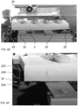
- FIG. 6A shows an image of the first magazine 10 of building blocks 2, which in the image are ceramic slabs with a flat attachment side, and with a thickness substantially smaller than the height and length of the slab.
- FIG. 6B illustrates a process stage where a building block 2 in the form of a slab is positioned on the conveyor 13 with its attachment side 2A oriented upwards, and where glue 29 is dispensed by the dispenser 21 onto the attachment side 2A.
- FIG. 6C illustrates a stage in the sequence where the building block 2 has been moved along the conveyor 13 to the end thereof and further onto two horizontal support pins 31 that are oriented lateral to the wall, advantageously rotational pins for easy sliding of the building block 2 onto the pins 31.
- the pins 31 support the building block 2 when it leaves the conveyor 13.
- a pair of lifting arms 32 are configured to move upwards and lift the building block 2 from the pins 31.
- FIG. 6D illustrates the stage where the lifting arms 32 have moved upwards and lifted the building block 2 from the pins 31 so that it now rests on the lifting arms 32.
- the profiled facade 3B is clearly visible with the ledges 17 and the trenches 16 in between, where the building blocks 2 shall be attached.
- FIG. 6E illustrates a stage where the jaws 22 have grabbed the building block 2 at its ends, which is then moved a distance away from the wall, while still on the lifting arms 32, in order to make room for driving the pins 31 up and out of the way for the building block 2, which is illustrated in FIG. 6G .
- FIG. 6F illustrates one of the jaws 22 in greater detail.
- the jaw 22 comprises a supporting portion 22A and a clamp portion 22B.
- the clamp portion 22B has at its foremost end a rounded part 22C, which is used as a lateral distance adjustment tool in that the rounded part 22C is inserted between adjacent building blocks 2.
- the clamp portion 22B with the rounded part 22C has a width in the order of the distance 18 of size Wand ensures a constant distance between adjacent building blocks 2.
- FIG. 6G illustrates the stage where the building block on the jaws 22 has been moved to the right to the position where the building block 2 is to be placed against the profiled facade 3B in extension of another building block 2 which is already glued to the wall. Also illustrated is the upwards movement of the pins 31 in order for the jaws 22 and the building block 2 to have unhindered access to the trench 16 in the profiled facade 3B.
- FIG. 6H illustrates the stage where the jaws 22 are rotating around a horizontal axle, which is parallel with the profiled facade 3B, see also position 25 in FIG. 1C , in order to orient the building block 2 towards the profiled facade 3B.
- the contact flange 30 is used for correct positioning of the building block 2 on the profiled façade 3B.
- FIG. 6J is a side view of the contact block 30. It comprises an edge portion 30A that protrudes into the trench 16 of the profiled facade 3B, and a notch 30B for taking up ledge 17 in order to ensure a proper steering by the jaws 22 and precise positioning of the building block 2 onto the profiled facade 3B. Also visible is a jaw 22 in the process of retraction from the contact block 30, the retraction combining a translation of the rotation flange 27 in a linear direction away from the contact block 30 and a subsequent rotation of the rotation flange 27 together with the jaws 22 about the rotation axle.
- the rotation flange 27 that holds the jaws 22 is provided with a guide roller 33
- the contact block 30 is provided with a cooperating slot 30C that is taking up the guide roller 33 in order to provide a precise and stable steering of the building block 2 by the jaws 22 against the profiled facade 3B.
- the cooperation of the guide roller 33 and the slot 30C as well as the cooperation between the notch 30B and the ledge 17 ensures precise placement of the building block 2 relatively to the horizontal trench 16 in the profiled facade 3B.
- the construction robot 1 comprises computer program instructions to automatically move the arrangement of magazine 10, 11, the glue container 12, the dispenser 21, the conveyor 13, and the gripper station 20 along the wall 3 and programmed to automatically attach the building blocks 2 against the wall at pre-calculated positions.
- the motors 7 comprise decoders so that the position of each component of the construction robot 1 is precisely known by the controller 8.
- laser scanners or cameras are advantageously used for the control of the position. Feedback loops on the basis of the scans or photo images of the wall are advantageously employed for high precision.
Landscapes
- Engineering & Computer Science (AREA)
- Architecture (AREA)
- Mechanical Engineering (AREA)
- Robotics (AREA)
- Civil Engineering (AREA)
- Structural Engineering (AREA)
- Conveying And Assembling Of Building Elements In Situ (AREA)
Claims (13)
- Robot de construction (1) pour attacher des parpaings (2) contre une surface verticale d'un mur vertical (3),
dans lequel le robot (1) comprend un groupe de composants, le groupe de composants incluant- un magasin (10) de parpaings (2), les parpaings (2) étant définis par une face d'attache pour l'attache au mur vertical (3), une seconde face opposée qui, après l'attache, fait face à l'opposé du mur (3), et des bords (2B) entourant la face d'attache et la seconde face ;- un récipient de colle (12) ;- un distributeur de colle (21) configuré pour distribuer automatiquement de la colle (14), à partir du récipient de colle (12), sur la face d'attache (2A) alors qu'elle est tournée vers le haut ;- un transporteur (13) pour automatiquement recevoir un parpaing (2) à partir du magasin (10) et pour déplacer le parpaing depuis le magasin jusqu'au distributeur de colle (21) dans une orientation où la face d'attache (2A) du parpaing (2) est tournée vers le haut, pour recevoir de la colle fournie par le distributeur de colle (21) ; caractérisé en ce que le robot de construction (1) comprend en outre :- une station d'organe de préhension (20) comprenant un organe de préhension suspendu de façon rotative et agencé pour recevoir le parpaing (2) à partir du transporteur (13) et pour prendre le parpaing (2) en utilisant l'organe de préhension, dans lequel l'organe de préhension est configuré pour retenir le parpaing (2) durant une rotation du parpaing (2) par la station d'organe de préhension (20) jusqu'à ce que la face d'attache (2A) soit verticale et fasse face à la surface verticale du mur vertical (3) ; et dans lequel la station d'organe de préhension (20) est configurée pour déplacer la face d'attache (2A) vers le mur (3) et avec la colle (14) en contact avec le mur (3) alors que le parpaing (2) est retenu par l'organe de préhension ;dans lequel le robot (1) comprend également un bâti (4) comprenant une poutre verticale (5) et une poutre horizontale (6) pour suspendre le groupe et des moteurs (7) pour déplacer le groupe horizontalement et verticalement le long du mur (3) et pour déplacer l'organe de préhension (22) vers le mur (3) pour l'attache du parpaing (2) sur le mur (3), dans lequel les moteurs (7) sont commandés par une unité de commande (8) programmée avec des instructions informatiques pour séquentiellement attacher des parpaings (2) les uns après les autres contre le mur (3) à des emplacements prédéterminés ;dans lequel l'organe de préhension comprend des mâchoires de serrage (22) configurées pour entrer en prise avec des bords opposés (2B) du parpaing (2) et retenir le parpaing (2) serré entre les mâchoires de serrage (22) par une force contre les bords (2B) ; dans lequel la station d'organe de préhension (20) est configurée pour recevoir le parpaing (2) à partir du transporteur (13) dans une première orientation et pour serrer les bords (2B) en utilisant les mâchoires de serrage (22), et, par la suite, tout en serrant les bords (2B), tourner les mâchoires de serrage (22), conjointement avec le parpaing (2), depuis la première orientation reçue jusqu'à une seconde orientation où la face d'attache (2A) est verticale et fait face au mur (3), dans lequel le robot de construction comprend une aile de contact (30) qui est mobile dans une direction vers le mur (3) indépendamment de la station d'organe de préhension (20) pour le contact avec le mur (3) avant un mouvement des mâchoires de serrage (2), avec le parpaing (2), vers et contre le mur (3), dans lequel une liaison mécanique (30C, 33) entre la station d'organe de préhension (20) et l'aile de contact (30) définit le mouvement des mâchoires de serrage (2) vers le mur (3) relativement à l'aile de contact (30), dans lequel la liaison mécanique comprend un galet de guidage (33) en tant que partie de la station d'organe de préhension (20) et une fente (30C) en tant que partie de l'aile de contact (30) pour l'insertion du galet de guidage (33) à l'intérieur de la fente (30C) durant l'avance des mâchoires de serrage (22) vers le mur (3). - Robot de construction (1) selon la revendication 1, dans lequel le robot de construction (1) comprend une unité de détection agencée et configurée pour détecter une distance horizontale (W+L) entre deux positions prédéfinies de parpaings (2, 2', 2") destinés à être agencés sur le même niveau vertical, dans lequel le robot de construction (1) est configuré pour positionner un parpaing (2, 2', 2") dans une position, dans laquelle la distance détectée (W+L) correspond à une valeur prédéfinie ou est au sein d'une plage prédéfinie.
- Robot de construction (1) selon la revendication 2, dans lequel l'unité de détection est agencée et configurée pour détecter la distance entre la portion la plus à gauche d'un parpaing (2) et la portion la plus à gauche du parpaing adjacent (2').
- Robot de construction (1) selon l'une des revendications précédentes, dans lequel les mâchoires de serrage (22) sont montées sur un axe rotatif (25) et configurées pour la rotation seulement dans une dimension de rotation pour mettre en rotation les mâchoires de serrage (22), conjointement avec le parpaing (2), depuis la première orientation jusqu'à la seconde orientation où la face d'attache (2A) est orientée verticalement pour l'attache à la surface verticale du mur vertical (3).
- Robot de construction selon l'une des revendications précédentes, dans lequel la face d'attache (2A) dans la première orientation est vers le haut, et la station d'organe de préhension (20) est configurée pour recevoir le parpaing (2) à partir du transporteur (13), avec la face d'attache (2A) orientée vers le haut, et pour serrer les bords (2B) en utilisant les mâchoires de serrage (22) alors que la face d'attache (2A) est toujours orientée vers le haut.
- Robot de construction selon l'une des revendications précédentes, dans lequel chacune des mâchoires de serrage (22) comprend une portion de support (22A) destinée à être contiguë à la seconde face du parpaing (2) et une portion de serrage (22B) destinée à serrer sur le bord, dans lequel la portion de serrage (22B) à une extrémité la plus en avant de la portion de serrage (22) est configurée pour l'inser-tion entre des parpaings adjacents (2) et pour définir une distance minimum entre les parpaings adjacents (2) lors du déplacement des mâchoires de serrage (22), avec le parpaing (2), vers le mur (3) pour monter le parpaing (2) à côté d'un autre.
- Procédé d'attache automatique de parpaings contre une surface verticale d'un mur vertical (3) ;dans lequel les parpaings (2) sont définis par une face d'attache pour l'attache au mur vertical (3), une seconde face opposée qui, après l'attache, fait face à l'opposé du mur (3), et des bords (2B) entourant la face d'attache et la seconde face ;dans lequel le procédé comprend la fourniture d'un robot de construction selon une quelconque revendication précédente, et le robot réalisant automatiquement la séquence automatisée suivante d'étapes :- sur un transporteur (13), la réception d'un parpaing (2) à partir d'un magasin (10) et le déplacement du parpaing (2) depuis le magasin (10) jusqu'à un distributeur de colle (21) dans une orientation où la face d'attache (2A) du parpaing (2) est tournée vers le haut ;- par le distributeur de colle (21), la distribution de colle (14), à partir d'un récipient de colle (12), sur la face d'attache (2A) alors qu'elle est tournée vers le haut ;- par une station d'organe de préhension (20), qui comprend un organe de préhension suspendu de façon rotative, la réception du parpaing (2) à partir du transporteur (13) et la prise du parpaing (2) par l'organe de préhension et la retenue du parpaing (2) durant une rotation du parpaing (2), par la station d'organe de préhension (20), jusqu'à ce que la face d'attache (2A) soit verticale et fasse face à la surface verticale du mur vertical (3) ; et, par la station d'organe de préhension (20), le déplacement de la face d'attache (2A) vers le mur (3) et la mise de la colle (14) en contact avec le mur (3) alors que le parpaing (2) est retenu par l'organe de préhension ;par un bâti (4) comprenant une poutre verticale (5) et une poutre horizontale (6) suspendant le groupe, l'utilisation de moteurs (7) pour déplacer le groupe horizontalement et verticalement le long du mur (3) et le déplacement de l'organe de préhension (22) vers le mur (3) pour l'attache du parpaing (2) sur le mur (3), dans lequel les moteurs (7) sont commandés par une unité de commande (8) programmée avec des instructions informatiques pour séquentiellement attacher des parpaings (2) les uns après les autres contre le mur (3) à des emplacements prédéterminés ;dans lequel l'organe de préhension comprend des mâchoires de serrage (22) entrant en prise avec des bords opposés (2B) du parpaing (2) et retenant le parpaing (2) serré entre les mâchoires de serrage (22) par force contre les bords (2B) ; dans lequel la station d'organe de préhension (20) reçoit le parpaing (2) à partir du transporteur (13) dans une première orientation et serre les bords (2B) en utilisant les mâchoires de serrage (22), et, par la suite, tout en serrant les bords (2B), tourne les mâchoires de serrage (22), conjointement avec le parpaing (2), depuis la première orientation reçue jusqu'à une seconde orientation où la face d'attache (2A) est verticale et fait face au mur (3), dans lequel le robot de construction (1) comprend une aile de contact (30) qui est mobile dans une direction vers le mur (3), indépendamment de la station d'organe de préhension (20), pour contact avec le mur (3), et dans lequel le procédé comprend d'abord le déplacement de l'aile de contact (30) en contact avec le mur (3) et puis le déplacement des mâchoires de serrage (2), avec le parpaing (2), vers et contre le mur (3), dans lequel une liaison mécanique (30C, 33) entre la station d'organe de préhension (20) et l'aile de contact (30) définit le mouvement des mâchoires de serrage (2) vers le mur (3) relativement à l'aile de contact (30), dans lequel la liaison mécanique comprend un galet de guidage (33) en tant que partie de la station d'organe de préhension (20) et une fente (30C) en tant que partie de l'aile de contact (30), et dans lequel le procédé comprend l'insertion du galet de guidage (33) à l'intérieur de la fente (30C) durant l'avance des mâchoires de serrage (22) vers le mur (3).
- Procédé selon la revendication 7, dans lequel les mâchoires de serrage (22) sont montées sur un axe rotatif (25) et configuré pour la rotation seulement dans une dimension de rotation, et dans lequel le procédé comprend la mise en rotation des mâchoires de serrage (22), conjointement avec le parpaing (2), sur l'axe rotatif (25) depuis la première orientation jusqu'à la seconde orientation.
- Procédé selon la revendication 7 ou 8, dans lequel la face d'attache (2A) dans la première orientation est vers le haut, et la station d'organe de préhension (20) reçoit le parpaing (2) à partir du transporteur (13), avec la face d'attache (2A) orientée vers le haut, et serre les bords (2B) en utilisant les mâchoires de serrage (22) alors que la face d'attache (2A) est toujours orientée vers le haut.
- Procédé selon l'une des revendications 7 à 9, dans lequel chacune des mâchoires de serrage (22) comprend une portion de support (22A) destinée à être contiguë à la seconde face du parpaing (2) et une portion de serrage (22B) destinée à serrer sur le bord, dans lequel la portion de serrage (22B) à une extrémité la plus en avant de la portion de serrage (22) comprend une partie arrondie (22C), dans lequel le procédé comprend l'insertion de l'extrémité la plus en avant entre des parpaings adjacents (2) pour définir une minimum distance entre les parpaings adjacents (2) tout en déplaçant les mâchoires de serrage (22), avec le parpaing (2), vers le mur (3) et pour monter le parpaing (2) à côté d'un autre.
- Procédé selon l'une quelconque des revendications 7 à 10, dans lequel le procédé comprend la fourniture d'une façade profilée (3B) en tant que partie du mur (3), la façade profilée comprenant des rebords horizontaux équidistants (17), avec des tranchées (16) entre ceux-ci, pour l'insertion des parpaings (2) dans les tranchées (16), dans lequel l'aile de contact (30) comprend une entaille (30B) pour l'insertion d'un rebord horizontal (17) dans l'entaille (30B), et dans lequel le procédé comprend en outre le déplacement de l'aile de contact (30) sur la façade profilée (3B) et l'insertion d'un rebord (17) à l'intérieur de l'entaille (30B) pour fixer une position de l'aile de contact (30) relativement au rebord (17) et à la tranchée (16), et puis le déplacement des mâchoires de serrage (22), avec le parpaing (2), vers et contre la façade profilée (3B) et le positionnement du parpaing (2) à l'intérieur de la tranchée (16), avec la colle contre la façade profilée (3b) à l'intérieur de la tranchée (16) et avec le parpaing (2) reposant sur le rebord (17) en tant que support.
- Procédé selon l'une des revendications 7 à 11, dans lequel le procédé comprend la fourniture des parpaings sous forme de dalle qui est allongée dans une direction longitudinale de la dalle et qui comprend deux extrémités, les deux extrémités comprenant les bords avec les zones les plus petites, et dans lequel le procédé comprend le transport de la dalle allongée sur le transporteur (13) dans une direction de transport, où la direction longitudinale est parallèle à la direction de transport, puis la préhension du parpaing (2), par les mâchoires de serrage (22), contre l'une ou l'autre extrémité de la dalle, et l'orientation de la dalle pour l'attache au mur, alors que la direction longitudinale est orientée horizontalement.
- Procédé selon l'une des revendications 7 à 12, dans lequel le procédé comprend l'étape de :- la détection d'une distance horizontale (W+L) entre deux positions prédéfinies de parpaings (2, 2', 2") destinés à être agencés sur le même niveau vertical, et- le positionnement d'un parpaing (2, 2', 2") dans une position, dans laquelle la distance détectée (W+L) correspond à une valeur prédéfinie ou est au sein d'une plage prédéfinie.
Applications Claiming Priority (1)
| Application Number | Priority Date | Filing Date | Title |
|---|---|---|---|
| DKPA202001465A DK180994B1 (en) | 2020-12-28 | 2020-12-28 | Construction robot and method of automatic attachment of building blocks against a vertical wall |
Publications (2)
| Publication Number | Publication Date |
|---|---|
| EP4032660A1 EP4032660A1 (fr) | 2022-07-27 |
| EP4032660B1 true EP4032660B1 (fr) | 2023-08-09 |
Family
ID=79171156
Family Applications (1)
| Application Number | Title | Priority Date | Filing Date |
|---|---|---|---|
| EP21217912.1A Active EP4032660B1 (fr) | 2020-12-28 | 2021-12-28 | Robot de construction et procédé de fixation automatique de blocs de construction contre une paroi verticale |
Country Status (2)
| Country | Link |
|---|---|
| EP (1) | EP4032660B1 (fr) |
| DK (1) | DK180994B1 (fr) |
Families Citing this family (4)
| Publication number | Priority date | Publication date | Assignee | Title |
|---|---|---|---|---|
| CN116374124B (zh) * | 2023-04-14 | 2025-12-09 | 江南造船(集团)有限责任公司 | 一种用于Mark III薄膜型围护系统的施工平台 |
| CN116517317B (zh) * | 2023-06-08 | 2025-07-15 | 广州城建职业学院 | 一种墙体砌筑装置 |
| CN117513767B (zh) * | 2023-11-06 | 2026-02-03 | 重庆建工住宅建设有限公司 | 一种装配式建筑外墙板施工防护结构 |
| CN121539126B (zh) * | 2026-01-12 | 2026-03-24 | 武汉孚锐利自动化设备有限公司 | 一种自动砌墙的自动化设备 |
Family Cites Families (6)
| Publication number | Priority date | Publication date | Assignee | Title |
|---|---|---|---|---|
| GB1465068A (en) * | 1973-09-20 | 1977-02-23 | Laing & Son Ltd John | Apparatus for the positioning of elements more particularly building elements |
| CN107786613B (zh) | 2016-08-30 | 2020-05-12 | 新华三技术有限公司 | 宽带远程接入服务器bras转发实现方法和装置 |
| CN107357294B (zh) | 2017-08-10 | 2020-04-03 | 厦门华蔚物联网科技有限公司 | 一种砌砖机器人的直线墙体的砌筑算法 |
| US12002240B2 (en) | 2018-09-04 | 2024-06-04 | Fastbrick Ip Pty Ltd. | Vision system for a robotic machine |
| CN108868169B (zh) * | 2018-09-10 | 2021-06-25 | 南通大学 | 一种砌墙机器人 |
| CN210879667U (zh) | 2019-07-04 | 2020-06-30 | 安徽创唯机器人科技产业园有限公司 | 一种铺墙瓷砖智能机器人 |
-
2020
- 2020-12-28 DK DKPA202001465A patent/DK180994B1/en active IP Right Grant
-
2021
- 2021-12-28 EP EP21217912.1A patent/EP4032660B1/fr active Active
Also Published As
| Publication number | Publication date |
|---|---|
| DK202001465A1 (en) | 2022-08-02 |
| DK180994B1 (en) | 2022-09-12 |
| EP4032660A1 (fr) | 2022-07-27 |
Similar Documents
| Publication | Publication Date | Title |
|---|---|---|
| EP4032660A1 (fr) | Robot de construction et procédé de fixation automatique de blocs de construction contre une paroi verticale | |
| CN210162717U (zh) | 翻转装置和光伏组件输送翻转系统 | |
| CN110744197B (zh) | 焊接设备 | |
| CN110536763A (zh) | 定中心装置 | |
| CN113635307B (zh) | 一种基于激光视觉引导的机器人定位抓取方法及系统 | |
| CN101987714B (zh) | 用于搬运机床的工件的机械装置、路面输送装置和方法以及用于机床的工件支座 | |
| EP2899149B1 (fr) | Dispositif de dépalettisation pour décharger des charges d'une palette et procédé pour décharger des charges d'une palette | |
| CN112551104B (zh) | 翻转定位机构的使用方法 | |
| CN211507602U (zh) | 晶圆支撑装置 | |
| JP3301004B2 (ja) | 端子挿入装置と端子姿勢矯正装置及び端子姿勢矯正方法並びに端子挿入方法 | |
| CN113216474A (zh) | 一种建筑外墙干挂石材幕墙铺装施工方法 | |
| CN104669271B (zh) | 抓取卡盘组件及三轴进给装置、装料机器人、加工系统 | |
| CN111392393A (zh) | 一种辊棒加工系统 | |
| EP3257794B1 (fr) | Table de traitement de verre comportant des zones de chargement et de traitement | |
| CN104670850B (zh) | 用于传输坯料的供给装置及其装料机器人、加工系统 | |
| EP4504389B1 (fr) | Dispositif et procédé de transfert automatisé de boîtiers | |
| CN111498481B (zh) | 一种激光去涂层自动化流水线 | |
| JPH0528162Y2 (fr) | ||
| CN115897958A (zh) | 铺贴执行机构、墙砖铺贴设备及墙砖铺贴方法 | |
| CN116696087B (zh) | 一种砌砖系统 | |
| CN112144902A (zh) | 一种可切砖的砌墙机器人 | |
| CN118107952B (zh) | 砌筑设备连续送砖系统 | |
| CN113103501B (zh) | 一种光电产品刮料设备及其刮料方法 | |
| CN224171691U (zh) | 物料交接系统 | |
| CN116101769B (zh) | 密封条胶套的输送装置以及输送方法 |
Legal Events
| Date | Code | Title | Description |
|---|---|---|---|
| PUAI | Public reference made under article 153(3) epc to a published international application that has entered the european phase |
Free format text: ORIGINAL CODE: 0009012 |
|
| STAA | Information on the status of an ep patent application or granted ep patent |
Free format text: STATUS: THE APPLICATION HAS BEEN PUBLISHED |
|
| AK | Designated contracting states |
Kind code of ref document: A1 Designated state(s): AL AT BE BG CH CY CZ DE DK EE ES FI FR GB GR HR HU IE IS IT LI LT LU LV MC MK MT NL NO PL PT RO RS SE SI SK SM TR |
|
| STAA | Information on the status of an ep patent application or granted ep patent |
Free format text: STATUS: REQUEST FOR EXAMINATION WAS MADE |
|
| 17P | Request for examination filed |
Effective date: 20230125 |
|
| RBV | Designated contracting states (corrected) |
Designated state(s): AL AT BE BG CH CY CZ DE DK EE ES FI FR GB GR HR HU IE IS IT LI LT LU LV MC MK MT NL NO PL PT RO RS SE SI SK SM TR |
|
| GRAP | Despatch of communication of intention to grant a patent |
Free format text: ORIGINAL CODE: EPIDOSNIGR1 |
|
| STAA | Information on the status of an ep patent application or granted ep patent |
Free format text: STATUS: GRANT OF PATENT IS INTENDED |
|
| INTG | Intention to grant announced |
Effective date: 20230307 |
|
| GRAS | Grant fee paid |
Free format text: ORIGINAL CODE: EPIDOSNIGR3 |
|
| GRAA | (expected) grant |
Free format text: ORIGINAL CODE: 0009210 |
|
| STAA | Information on the status of an ep patent application or granted ep patent |
Free format text: STATUS: THE PATENT HAS BEEN GRANTED |
|
| AK | Designated contracting states |
Kind code of ref document: B1 Designated state(s): AL AT BE BG CH CY CZ DE DK EE ES FI FR GB GR HR HU IE IS IT LI LT LU LV MC MK MT NL NO PL PT RO RS SE SI SK SM TR |
|
| REG | Reference to a national code |
Ref country code: GB Ref legal event code: FG4D |
|
| REG | Reference to a national code |
Ref country code: CH Ref legal event code: EP |
|
| REG | Reference to a national code |
Ref country code: IE Ref legal event code: FG4D |
|
| REG | Reference to a national code |
Ref country code: DE Ref legal event code: R096 Ref document number: 602021004166 Country of ref document: DE |
|
| REG | Reference to a national code |
Ref country code: LT Ref legal event code: MG9D |
|
| REG | Reference to a national code |
Ref country code: NL Ref legal event code: MP Effective date: 20230809 |
|
| REG | Reference to a national code |
Ref country code: AT Ref legal event code: MK05 Ref document number: 1596961 Country of ref document: AT Kind code of ref document: T Effective date: 20230809 |
|
| PG25 | Lapsed in a contracting state [announced via postgrant information from national office to epo] |
Ref country code: GR Free format text: LAPSE BECAUSE OF FAILURE TO SUBMIT A TRANSLATION OF THE DESCRIPTION OR TO PAY THE FEE WITHIN THE PRESCRIBED TIME-LIMIT Effective date: 20231110 |
|
| PG25 | Lapsed in a contracting state [announced via postgrant information from national office to epo] |
Ref country code: IS Free format text: LAPSE BECAUSE OF FAILURE TO SUBMIT A TRANSLATION OF THE DESCRIPTION OR TO PAY THE FEE WITHIN THE PRESCRIBED TIME-LIMIT Effective date: 20231209 |
|
| PG25 | Lapsed in a contracting state [announced via postgrant information from national office to epo] |
Ref country code: SE Free format text: LAPSE BECAUSE OF FAILURE TO SUBMIT A TRANSLATION OF THE DESCRIPTION OR TO PAY THE FEE WITHIN THE PRESCRIBED TIME-LIMIT Effective date: 20230809 Ref country code: RS Free format text: LAPSE BECAUSE OF FAILURE TO SUBMIT A TRANSLATION OF THE DESCRIPTION OR TO PAY THE FEE WITHIN THE PRESCRIBED TIME-LIMIT Effective date: 20230809 Ref country code: PT Free format text: LAPSE BECAUSE OF FAILURE TO SUBMIT A TRANSLATION OF THE DESCRIPTION OR TO PAY THE FEE WITHIN THE PRESCRIBED TIME-LIMIT Effective date: 20231211 Ref country code: NO Free format text: LAPSE BECAUSE OF FAILURE TO SUBMIT A TRANSLATION OF THE DESCRIPTION OR TO PAY THE FEE WITHIN THE PRESCRIBED TIME-LIMIT Effective date: 20231109 Ref country code: NL Free format text: LAPSE BECAUSE OF FAILURE TO SUBMIT A TRANSLATION OF THE DESCRIPTION OR TO PAY THE FEE WITHIN THE PRESCRIBED TIME-LIMIT Effective date: 20230809 Ref country code: LV Free format text: LAPSE BECAUSE OF FAILURE TO SUBMIT A TRANSLATION OF THE DESCRIPTION OR TO PAY THE FEE WITHIN THE PRESCRIBED TIME-LIMIT Effective date: 20230809 Ref country code: LT Free format text: LAPSE BECAUSE OF FAILURE TO SUBMIT A TRANSLATION OF THE DESCRIPTION OR TO PAY THE FEE WITHIN THE PRESCRIBED TIME-LIMIT Effective date: 20230809 Ref country code: IS Free format text: LAPSE BECAUSE OF FAILURE TO SUBMIT A TRANSLATION OF THE DESCRIPTION OR TO PAY THE FEE WITHIN THE PRESCRIBED TIME-LIMIT Effective date: 20231209 Ref country code: HR Free format text: LAPSE BECAUSE OF FAILURE TO SUBMIT A TRANSLATION OF THE DESCRIPTION OR TO PAY THE FEE WITHIN THE PRESCRIBED TIME-LIMIT Effective date: 20230809 Ref country code: GR Free format text: LAPSE BECAUSE OF FAILURE TO SUBMIT A TRANSLATION OF THE DESCRIPTION OR TO PAY THE FEE WITHIN THE PRESCRIBED TIME-LIMIT Effective date: 20231110 Ref country code: FI Free format text: LAPSE BECAUSE OF FAILURE TO SUBMIT A TRANSLATION OF THE DESCRIPTION OR TO PAY THE FEE WITHIN THE PRESCRIBED TIME-LIMIT Effective date: 20230809 Ref country code: AT Free format text: LAPSE BECAUSE OF FAILURE TO SUBMIT A TRANSLATION OF THE DESCRIPTION OR TO PAY THE FEE WITHIN THE PRESCRIBED TIME-LIMIT Effective date: 20230809 |
|
| PG25 | Lapsed in a contracting state [announced via postgrant information from national office to epo] |
Ref country code: PL Free format text: LAPSE BECAUSE OF FAILURE TO SUBMIT A TRANSLATION OF THE DESCRIPTION OR TO PAY THE FEE WITHIN THE PRESCRIBED TIME-LIMIT Effective date: 20230809 |
|
| PG25 | Lapsed in a contracting state [announced via postgrant information from national office to epo] |
Ref country code: ES Free format text: LAPSE BECAUSE OF FAILURE TO SUBMIT A TRANSLATION OF THE DESCRIPTION OR TO PAY THE FEE WITHIN THE PRESCRIBED TIME-LIMIT Effective date: 20230809 |
|
| PG25 | Lapsed in a contracting state [announced via postgrant information from national office to epo] |
Ref country code: SM Free format text: LAPSE BECAUSE OF FAILURE TO SUBMIT A TRANSLATION OF THE DESCRIPTION OR TO PAY THE FEE WITHIN THE PRESCRIBED TIME-LIMIT Effective date: 20230809 Ref country code: RO Free format text: LAPSE BECAUSE OF FAILURE TO SUBMIT A TRANSLATION OF THE DESCRIPTION OR TO PAY THE FEE WITHIN THE PRESCRIBED TIME-LIMIT Effective date: 20230809 Ref country code: ES Free format text: LAPSE BECAUSE OF FAILURE TO SUBMIT A TRANSLATION OF THE DESCRIPTION OR TO PAY THE FEE WITHIN THE PRESCRIBED TIME-LIMIT Effective date: 20230809 Ref country code: EE Free format text: LAPSE BECAUSE OF FAILURE TO SUBMIT A TRANSLATION OF THE DESCRIPTION OR TO PAY THE FEE WITHIN THE PRESCRIBED TIME-LIMIT Effective date: 20230809 Ref country code: DK Free format text: LAPSE BECAUSE OF FAILURE TO SUBMIT A TRANSLATION OF THE DESCRIPTION OR TO PAY THE FEE WITHIN THE PRESCRIBED TIME-LIMIT Effective date: 20230809 Ref country code: CZ Free format text: LAPSE BECAUSE OF FAILURE TO SUBMIT A TRANSLATION OF THE DESCRIPTION OR TO PAY THE FEE WITHIN THE PRESCRIBED TIME-LIMIT Effective date: 20230809 Ref country code: SK Free format text: LAPSE BECAUSE OF FAILURE TO SUBMIT A TRANSLATION OF THE DESCRIPTION OR TO PAY THE FEE WITHIN THE PRESCRIBED TIME-LIMIT Effective date: 20230809 |
|
| REG | Reference to a national code |
Ref country code: DE Ref legal event code: R097 Ref document number: 602021004166 Country of ref document: DE |
|
| PG25 | Lapsed in a contracting state [announced via postgrant information from national office to epo] |
Ref country code: IT Free format text: LAPSE BECAUSE OF FAILURE TO SUBMIT A TRANSLATION OF THE DESCRIPTION OR TO PAY THE FEE WITHIN THE PRESCRIBED TIME-LIMIT Effective date: 20230809 |
|
| PLBE | No opposition filed within time limit |
Free format text: ORIGINAL CODE: 0009261 |
|
| STAA | Information on the status of an ep patent application or granted ep patent |
Free format text: STATUS: NO OPPOSITION FILED WITHIN TIME LIMIT |
|
| 26N | No opposition filed |
Effective date: 20240513 |
|
| PG25 | Lapsed in a contracting state [announced via postgrant information from national office to epo] |
Ref country code: SI Free format text: LAPSE BECAUSE OF FAILURE TO SUBMIT A TRANSLATION OF THE DESCRIPTION OR TO PAY THE FEE WITHIN THE PRESCRIBED TIME-LIMIT Effective date: 20230809 |
|
| PG25 | Lapsed in a contracting state [announced via postgrant information from national office to epo] |
Ref country code: LU Free format text: LAPSE BECAUSE OF NON-PAYMENT OF DUE FEES Effective date: 20231228 |
|
| PG25 | Lapsed in a contracting state [announced via postgrant information from national office to epo] |
Ref country code: MC Free format text: LAPSE BECAUSE OF FAILURE TO SUBMIT A TRANSLATION OF THE DESCRIPTION OR TO PAY THE FEE WITHIN THE PRESCRIBED TIME-LIMIT Effective date: 20230809 |
|
| REG | Reference to a national code |
Ref country code: BE Ref legal event code: MM Effective date: 20231231 |
|
| PG25 | Lapsed in a contracting state [announced via postgrant information from national office to epo] |
Ref country code: MC Free format text: LAPSE BECAUSE OF FAILURE TO SUBMIT A TRANSLATION OF THE DESCRIPTION OR TO PAY THE FEE WITHIN THE PRESCRIBED TIME-LIMIT Effective date: 20230809 Ref country code: LU Free format text: LAPSE BECAUSE OF NON-PAYMENT OF DUE FEES Effective date: 20231228 |
|
| REG | Reference to a national code |
Ref country code: IE Ref legal event code: MM4A |
|
| PG25 | Lapsed in a contracting state [announced via postgrant information from national office to epo] |
Ref country code: IE Free format text: LAPSE BECAUSE OF NON-PAYMENT OF DUE FEES Effective date: 20231228 |
|
| PG25 | Lapsed in a contracting state [announced via postgrant information from national office to epo] |
Ref country code: BE Free format text: LAPSE BECAUSE OF NON-PAYMENT OF DUE FEES Effective date: 20231231 |
|
| PG25 | Lapsed in a contracting state [announced via postgrant information from national office to epo] |
Ref country code: IE Free format text: LAPSE BECAUSE OF NON-PAYMENT OF DUE FEES Effective date: 20231228 Ref country code: BE Free format text: LAPSE BECAUSE OF NON-PAYMENT OF DUE FEES Effective date: 20231231 |
|
| PG25 | Lapsed in a contracting state [announced via postgrant information from national office to epo] |
Ref country code: BG Free format text: LAPSE BECAUSE OF FAILURE TO SUBMIT A TRANSLATION OF THE DESCRIPTION OR TO PAY THE FEE WITHIN THE PRESCRIBED TIME-LIMIT Effective date: 20230809 |
|
| PG25 | Lapsed in a contracting state [announced via postgrant information from national office to epo] |
Ref country code: BG Free format text: LAPSE BECAUSE OF FAILURE TO SUBMIT A TRANSLATION OF THE DESCRIPTION OR TO PAY THE FEE WITHIN THE PRESCRIBED TIME-LIMIT Effective date: 20230809 |
|
| PG25 | Lapsed in a contracting state [announced via postgrant information from national office to epo] |
Ref country code: CY Free format text: LAPSE BECAUSE OF FAILURE TO SUBMIT A TRANSLATION OF THE DESCRIPTION OR TO PAY THE FEE WITHIN THE PRESCRIBED TIME-LIMIT; INVALID AB INITIO Effective date: 20211228 |
|
| REG | Reference to a national code |
Ref country code: CH Ref legal event code: PL |
|
| PG25 | Lapsed in a contracting state [announced via postgrant information from national office to epo] |
Ref country code: CH Free format text: LAPSE BECAUSE OF NON-PAYMENT OF DUE FEES Effective date: 20241231 |
|
| PG25 | Lapsed in a contracting state [announced via postgrant information from national office to epo] |
Ref country code: TR Free format text: LAPSE BECAUSE OF FAILURE TO SUBMIT A TRANSLATION OF THE DESCRIPTION OR TO PAY THE FEE WITHIN THE PRESCRIBED TIME-LIMIT Effective date: 20230809 |
|
| PGFP | Annual fee paid to national office [announced via postgrant information from national office to epo] |
Ref country code: GB Payment date: 20251229 Year of fee payment: 5 |
|
| PGFP | Annual fee paid to national office [announced via postgrant information from national office to epo] |
Ref country code: FR Payment date: 20251226 Year of fee payment: 5 |
|
| PGFP | Annual fee paid to national office [announced via postgrant information from national office to epo] |
Ref country code: DE Payment date: 20251229 Year of fee payment: 5 |
|
| PG25 | Lapsed in a contracting state [announced via postgrant information from national office to epo] |
Ref country code: HU Free format text: LAPSE BECAUSE OF FAILURE TO SUBMIT A TRANSLATION OF THE DESCRIPTION OR TO PAY THE FEE WITHIN THE PRESCRIBED TIME-LIMIT; INVALID AB INITIO Effective date: 20211228 |