EP4032689A1 - Thermoscelleuse pour générer des emballages faciles à ouvrir - Google Patents
Thermoscelleuse pour générer des emballages faciles à ouvrir Download PDFInfo
- Publication number
- EP4032689A1 EP4032689A1 EP21382051.7A EP21382051A EP4032689A1 EP 4032689 A1 EP4032689 A1 EP 4032689A1 EP 21382051 A EP21382051 A EP 21382051A EP 4032689 A1 EP4032689 A1 EP 4032689A1
- Authority
- EP
- European Patent Office
- Prior art keywords
- tool
- rod
- cover film
- actuation
- support
- Prior art date
- Legal status (The legal status is an assumption and is not a legal conclusion. Google has not performed a legal analysis and makes no representation as to the accuracy of the status listed.)
- Withdrawn
Links
- 238000007789 sealing Methods 0.000 title claims abstract description 90
- 239000013039 cover film Substances 0.000 claims abstract description 89
- 238000002347 injection Methods 0.000 claims description 8
- 239000007924 injection Substances 0.000 claims description 8
- 238000004806 packaging method and process Methods 0.000 description 4
- 239000000243 solution Substances 0.000 description 3
- 235000013305 food Nutrition 0.000 description 2
- 238000010438 heat treatment Methods 0.000 description 2
- 230000006835 compression Effects 0.000 description 1
- 238000007906 compression Methods 0.000 description 1
- 239000010408 film Substances 0.000 description 1
- 238000004519 manufacturing process Methods 0.000 description 1
- 239000000463 material Substances 0.000 description 1
- 238000000926 separation method Methods 0.000 description 1
Images



Classifications
-
- B—PERFORMING OPERATIONS; TRANSPORTING
- B29—WORKING OF PLASTICS; WORKING OF SUBSTANCES IN A PLASTIC STATE IN GENERAL
- B29C—SHAPING OR JOINING OF PLASTICS; SHAPING OF MATERIAL IN A PLASTIC STATE, NOT OTHERWISE PROVIDED FOR; AFTER-TREATMENT OF THE SHAPED PRODUCTS, e.g. REPAIRING
- B29C65/00—Joining or sealing of preformed parts, e.g. welding of plastics materials; Apparatus therefor
- B29C65/02—Joining or sealing of preformed parts, e.g. welding of plastics materials; Apparatus therefor by heating, with or without pressure
-
- B—PERFORMING OPERATIONS; TRANSPORTING
- B29—WORKING OF PLASTICS; WORKING OF SUBSTANCES IN A PLASTIC STATE IN GENERAL
- B29C—SHAPING OR JOINING OF PLASTICS; SHAPING OF MATERIAL IN A PLASTIC STATE, NOT OTHERWISE PROVIDED FOR; AFTER-TREATMENT OF THE SHAPED PRODUCTS, e.g. REPAIRING
- B29C65/00—Joining or sealing of preformed parts, e.g. welding of plastics materials; Apparatus therefor
- B29C65/74—Joining or sealing of preformed parts, e.g. welding of plastics materials; Apparatus therefor by welding and severing, or by joining and severing, the severing being performed in the area to be joined, next to the area to be joined, in the joint area or next to the joint area
- B29C65/745—Joining or sealing of preformed parts, e.g. welding of plastics materials; Apparatus therefor by welding and severing, or by joining and severing, the severing being performed in the area to be joined, next to the area to be joined, in the joint area or next to the joint area using a single unit having both a severing tool and a welding tool
- B29C65/7457—Joining or sealing of preformed parts, e.g. welding of plastics materials; Apparatus therefor by welding and severing, or by joining and severing, the severing being performed in the area to be joined, next to the area to be joined, in the joint area or next to the joint area using a single unit having both a severing tool and a welding tool comprising a perforating tool
-
- B—PERFORMING OPERATIONS; TRANSPORTING
- B29—WORKING OF PLASTICS; WORKING OF SUBSTANCES IN A PLASTIC STATE IN GENERAL
- B29C—SHAPING OR JOINING OF PLASTICS; SHAPING OF MATERIAL IN A PLASTIC STATE, NOT OTHERWISE PROVIDED FOR; AFTER-TREATMENT OF THE SHAPED PRODUCTS, e.g. REPAIRING
- B29C65/00—Joining or sealing of preformed parts, e.g. welding of plastics materials; Apparatus therefor
- B29C65/74—Joining or sealing of preformed parts, e.g. welding of plastics materials; Apparatus therefor by welding and severing, or by joining and severing, the severing being performed in the area to be joined, next to the area to be joined, in the joint area or next to the joint area
- B29C65/745—Joining or sealing of preformed parts, e.g. welding of plastics materials; Apparatus therefor by welding and severing, or by joining and severing, the severing being performed in the area to be joined, next to the area to be joined, in the joint area or next to the joint area using a single unit having both a severing tool and a welding tool
- B29C65/7461—Joining or sealing of preformed parts, e.g. welding of plastics materials; Apparatus therefor by welding and severing, or by joining and severing, the severing being performed in the area to be joined, next to the area to be joined, in the joint area or next to the joint area using a single unit having both a severing tool and a welding tool for making welds and cuts of other than simple rectilinear form
-
- B—PERFORMING OPERATIONS; TRANSPORTING
- B29—WORKING OF PLASTICS; WORKING OF SUBSTANCES IN A PLASTIC STATE IN GENERAL
- B29C—SHAPING OR JOINING OF PLASTICS; SHAPING OF MATERIAL IN A PLASTIC STATE, NOT OTHERWISE PROVIDED FOR; AFTER-TREATMENT OF THE SHAPED PRODUCTS, e.g. REPAIRING
- B29C65/00—Joining or sealing of preformed parts, e.g. welding of plastics materials; Apparatus therefor
- B29C65/76—Making non-permanent or releasable joints
-
- B—PERFORMING OPERATIONS; TRANSPORTING
- B29—WORKING OF PLASTICS; WORKING OF SUBSTANCES IN A PLASTIC STATE IN GENERAL
- B29C—SHAPING OR JOINING OF PLASTICS; SHAPING OF MATERIAL IN A PLASTIC STATE, NOT OTHERWISE PROVIDED FOR; AFTER-TREATMENT OF THE SHAPED PRODUCTS, e.g. REPAIRING
- B29C65/00—Joining or sealing of preformed parts, e.g. welding of plastics materials; Apparatus therefor
- B29C65/78—Means for handling the parts to be joined, e.g. for making containers or hollow articles, e.g. means for handling sheets, plates, web-like materials, tubular articles, hollow articles or elements to be joined therewith; Means for discharging the joined articles from the joining apparatus
- B29C65/7897—Means for discharging the joined articles from the joining apparatus
-
- B—PERFORMING OPERATIONS; TRANSPORTING
- B29—WORKING OF PLASTICS; WORKING OF SUBSTANCES IN A PLASTIC STATE IN GENERAL
- B29C—SHAPING OR JOINING OF PLASTICS; SHAPING OF MATERIAL IN A PLASTIC STATE, NOT OTHERWISE PROVIDED FOR; AFTER-TREATMENT OF THE SHAPED PRODUCTS, e.g. REPAIRING
- B29C66/00—General aspects of processes or apparatus for joining preformed parts
- B29C66/01—General aspects dealing with the joint area or with the area to be joined
- B29C66/05—Particular design of joint configurations
- B29C66/10—Particular design of joint configurations particular design of the joint cross-sections
- B29C66/11—Joint cross-sections comprising a single joint-segment, i.e. one of the parts to be joined comprising a single joint-segment in the joint cross-section
- B29C66/112—Single lapped joints
-
- B—PERFORMING OPERATIONS; TRANSPORTING
- B29—WORKING OF PLASTICS; WORKING OF SUBSTANCES IN A PLASTIC STATE IN GENERAL
- B29C—SHAPING OR JOINING OF PLASTICS; SHAPING OF MATERIAL IN A PLASTIC STATE, NOT OTHERWISE PROVIDED FOR; AFTER-TREATMENT OF THE SHAPED PRODUCTS, e.g. REPAIRING
- B29C66/00—General aspects of processes or apparatus for joining preformed parts
- B29C66/01—General aspects dealing with the joint area or with the area to be joined
- B29C66/05—Particular design of joint configurations
- B29C66/10—Particular design of joint configurations particular design of the joint cross-sections
- B29C66/13—Single flanged joints; Fin-type joints; Single hem joints; Edge joints; Interpenetrating fingered joints; Other specific particular designs of joint cross-sections not provided for in groups B29C66/11 - B29C66/12
- B29C66/131—Single flanged joints, i.e. one of the parts to be joined being rigid and flanged in the joint area
-
- B—PERFORMING OPERATIONS; TRANSPORTING
- B29—WORKING OF PLASTICS; WORKING OF SUBSTANCES IN A PLASTIC STATE IN GENERAL
- B29C—SHAPING OR JOINING OF PLASTICS; SHAPING OF MATERIAL IN A PLASTIC STATE, NOT OTHERWISE PROVIDED FOR; AFTER-TREATMENT OF THE SHAPED PRODUCTS, e.g. REPAIRING
- B29C66/00—General aspects of processes or apparatus for joining preformed parts
- B29C66/50—General aspects of joining tubular articles; General aspects of joining long products, i.e. bars or profiled elements; General aspects of joining single elements to tubular articles, hollow articles or bars; General aspects of joining several hollow-preforms to form hollow or tubular articles
- B29C66/51—Joining tubular articles, profiled elements or bars; Joining single elements to tubular articles, hollow articles or bars; Joining several hollow-preforms to form hollow or tubular articles
- B29C66/53—Joining single elements to tubular articles, hollow articles or bars
- B29C66/534—Joining single elements to open ends of tubular or hollow articles or to the ends of bars
- B29C66/5346—Joining single elements to open ends of tubular or hollow articles or to the ends of bars said single elements being substantially flat
- B29C66/53461—Joining single elements to open ends of tubular or hollow articles or to the ends of bars said single elements being substantially flat joining substantially flat covers and/or substantially flat bottoms to open ends of container bodies
-
- B—PERFORMING OPERATIONS; TRANSPORTING
- B29—WORKING OF PLASTICS; WORKING OF SUBSTANCES IN A PLASTIC STATE IN GENERAL
- B29C—SHAPING OR JOINING OF PLASTICS; SHAPING OF MATERIAL IN A PLASTIC STATE, NOT OTHERWISE PROVIDED FOR; AFTER-TREATMENT OF THE SHAPED PRODUCTS, e.g. REPAIRING
- B29C66/00—General aspects of processes or apparatus for joining preformed parts
- B29C66/80—General aspects of machine operations or constructions and parts thereof
- B29C66/83—General aspects of machine operations or constructions and parts thereof characterised by the movement of the joining or pressing tools
- B29C66/832—Reciprocating joining or pressing tools
- B29C66/8322—Joining or pressing tools reciprocating along one axis
-
- B—PERFORMING OPERATIONS; TRANSPORTING
- B29—WORKING OF PLASTICS; WORKING OF SUBSTANCES IN A PLASTIC STATE IN GENERAL
- B29C—SHAPING OR JOINING OF PLASTICS; SHAPING OF MATERIAL IN A PLASTIC STATE, NOT OTHERWISE PROVIDED FOR; AFTER-TREATMENT OF THE SHAPED PRODUCTS, e.g. REPAIRING
- B29C66/00—General aspects of processes or apparatus for joining preformed parts
- B29C66/80—General aspects of machine operations or constructions and parts thereof
- B29C66/84—Specific machine types or machines suitable for specific applications
- B29C66/849—Packaging machines
-
- B—PERFORMING OPERATIONS; TRANSPORTING
- B65—CONVEYING; PACKING; STORING; HANDLING THIN OR FILAMENTARY MATERIAL
- B65B—MACHINES, APPARATUS OR DEVICES FOR, OR METHODS OF, PACKAGING ARTICLES OR MATERIALS; UNPACKING
- B65B51/00—Devices for, or methods of, sealing or securing package folds or closures; Devices for gathering or twisting wrappers, or necks of bags
- B65B51/10—Applying or generating heat or pressure or combinations thereof
- B65B51/14—Applying or generating heat or pressure or combinations thereof by reciprocating or oscillating members
-
- B—PERFORMING OPERATIONS; TRANSPORTING
- B65—CONVEYING; PACKING; STORING; HANDLING THIN OR FILAMENTARY MATERIAL
- B65B—MACHINES, APPARATUS OR DEVICES FOR, OR METHODS OF, PACKAGING ARTICLES OR MATERIALS; UNPACKING
- B65B61/00—Auxiliary devices, not otherwise provided for, for operating on sheets, blanks, webs, binding material, containers or packages
- B65B61/18—Auxiliary devices, not otherwise provided for, for operating on sheets, blanks, webs, binding material, containers or packages for making package-opening or unpacking elements
-
- B—PERFORMING OPERATIONS; TRANSPORTING
- B65—CONVEYING; PACKING; STORING; HANDLING THIN OR FILAMENTARY MATERIAL
- B65B—MACHINES, APPARATUS OR DEVICES FOR, OR METHODS OF, PACKAGING ARTICLES OR MATERIALS; UNPACKING
- B65B7/00—Closing containers or receptacles after filling
- B65B7/16—Closing semi-rigid or rigid containers or receptacles not deformed by, or not taking-up shape of, contents, e.g. boxes or cartons
- B65B7/162—Closing semi-rigid or rigid containers or receptacles not deformed by, or not taking-up shape of, contents, e.g. boxes or cartons by feeding web material to securing means
- B65B7/164—Securing by heat-sealing
-
- B—PERFORMING OPERATIONS; TRANSPORTING
- B29—WORKING OF PLASTICS; WORKING OF SUBSTANCES IN A PLASTIC STATE IN GENERAL
- B29L—INDEXING SCHEME ASSOCIATED WITH SUBCLASS B29C, RELATING TO PARTICULAR ARTICLES
- B29L2031/00—Other particular articles
- B29L2031/712—Containers; Packaging elements or accessories, Packages
- B29L2031/7162—Boxes, cartons, cases
- B29L2031/7164—Blister packages
-
- B—PERFORMING OPERATIONS; TRANSPORTING
- B65—CONVEYING; PACKING; STORING; HANDLING THIN OR FILAMENTARY MATERIAL
- B65B—MACHINES, APPARATUS OR DEVICES FOR, OR METHODS OF, PACKAGING ARTICLES OR MATERIALS; UNPACKING
- B65B61/00—Auxiliary devices, not otherwise provided for, for operating on sheets, blanks, webs, binding material, containers or packages
- B65B61/04—Auxiliary devices, not otherwise provided for, for operating on sheets, blanks, webs, binding material, containers or packages for severing webs, or for separating joined packages
- B65B61/06—Auxiliary devices, not otherwise provided for, for operating on sheets, blanks, webs, binding material, containers or packages for severing webs, or for separating joined packages by cutting
- B65B61/065—Auxiliary devices, not otherwise provided for, for operating on sheets, blanks, webs, binding material, containers or packages for severing webs, or for separating joined packages by cutting by punching out
Definitions
- the present invention relates to heat-sealing machines in which a cover film is sealed to a tray in a sealing station, and particularly to heat-sealing machines which are configured for generating easy-open packages.
- packages of this type are formed by a tray (a flat tray or one which defines a cavity), and a cover film sealed to the tray. The foods stay packaged between the cover film and the tray.
- the object of the invention is to provide a heat-sealing machine for generating easy-open packages, as defined in the claims.
- the machine comprises a sealing station with an upper tool and a lower tool facing one another and configured for holding the cover film between them in a closed position of the sealing station.
- the upper tool comprises a sealing tool which defines a closed contour and is configured for pressing the cover film against the tray, sealing said cover film to said tray with said pressure, with the sealing station in the closed position; a cutting tool which externally goes around the contour of the sealing tool and is configured for pressing the cover film against the tray and for cutting said cover film on the tray as a result of said pressure, with the sealing station in the closed position; and an actuation area between said sealing tool and said cutting tool.
- the lower tool comprises a support which is configured for supporting the tray, with an area of the support facing the actuation area of the upper tool being an actuation area of said support.
- the machine further comprises actuation means in the sealing station, which are configured, with the sealing station in the closed position, for acting on the actuation area of the upper tool or on the actuation area of the lower tool once the cutting tool has cut the cover film on the tray, such that with said actuation at least part of the cover film facing said actuation area of the upper tool is caused to move away from the cutting tool.
- Said actuation can start before said cut is made, during cutting, or after the cut has been made.
- the pressure exerted by the cutting tool when cutting the cover film against the tray and the heat provided by the sealing tool to the cutting tool and/or to the actuation area are thereby prevented from causing one end of the cover film which will be part of the package to remain adhered to said tray in the actuation area.
- the actuation of the actuation means causes said end of the cover film to move away from the cutting tool, preventing said end of the cover film from adhering to the tray or separating said end from the tray if it had adhered thereto. This thereby allows an easy-open package to be obtained without the cover film protruding from the tray, the amount of cover film used being reduced in addition to maintaining the advantage of being able to readily recycle the tray on one hand and the cover film on the other.
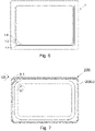
- FIG 1 shows in a simplified manner an embodiment of the heat-sealing machine 100 of the invention, which is configured for generating easy-open packages 200, such as the one the shown in Figures 7 and 8 .
- the machine 100 comprises a sealing station 101 comprising an upper tool 1 and a lower tool 2 facing one another and configured for being spaced apart from one another in an open position of the sealing station 101, and for being in contact in a closed position of said sealing station 101.
- Said sealing station 101 is suitable for receiving a cover film 4 and at least one tray 5 (a flat tray or one with a flap around a cavity) between the two tools 1 and 2, and in the closed position the cover film 4 is held between the two tools 1 and 2.
- the machine 100 comprises a film feeder 104 for supplying the cover film 4 to the sealing station 101 and may comprise a tray feeder, not depicted in the figures, although said trays 5 could be supplied manually.
- the upper tool 1 comprises a sealing tool 1.0 which defines a closed contour and is configured for being able to seal the cover film 4 to the tray 5 by heat, pressing said cover film 4 against the tray 5 ( Figures 7 and 8 show by way of example a sealing area 200.0 between the tray 5 and the cover film 4).
- the sealing station 101 comprises heating means, not depicted in the figures, configured for heating said sealing tool 1.0.
- the upper tool 1 further comprises a cutting tool 1.1, a blade for example, which externally goes around the contour of the sealing tool 1.0 and an actuation area 1.2 between said sealing tool 1.0 and said cutting tool 1.1.
- the cutting tool 1.1 is configured for pressing the cover film 4 against the tray 5 and for cutting said cover film 4 on said tray 5 as a result of said pressure (without cutting said tray 5).
- the sealing tool 1.0 and the cutting tool 1.1 are configured for acting on the cover film 4 with the sealing station 101 in the closed position.
- the cut made on the cover film 4 is a cut which defines a closed contour, such that individual packages 200 are obtained.
- Packaging machines 100 suitable for performing said sealing on pre-formed trays are known as heat-sealing machines.
- the operation is generally as follows: with the sealing station 101 in the closed position, such that the tools 1 and 2 hold the cover film 4, at first the sealing tool 1.0 does not cooperate with the lower tool 2 and does not seal the cover film 4 to the tray 5.
- the sealing tool 1.0 is caused to move towards the lower tool 2. During this movement, said sealing tool 1.0 contacts the cover film 4 and presses it against the tray 5, causing them to seal together.
- the cutting tool 1.1 is preferably moved integrally with said sealing tool 1.0 so as to cut said cover film 4 on the tray 5.
- the lower tool 2 in turn, comprises a support 2.0 which is configured for supporting the tray 5, the area of the support 2.0 facing the actuation area 1.2 of the upper tool 1 being an actuation area 2.2 of said support 2.0.
- the machine 100 comprises actuation means configured, with the sealing station 101 in the closed position and once the cutting tool 1.1 has cut the cover film 4 on the tray 5, for acting on the actuation area 1.2 of the upper tool 1 or on the actuation area 2.2 of the lower tool 2, such that with said actuation at least part of the cover film 4 facing said actuation area 1.2 of the upper tool 1 is caused to move away from the cutting tool 1.1.
- the actuation of the actuation means is furthermore preferably generated while the sealing tool 1.0 and/or the cutting tool 1.1 are pressing the cover film 4 against the tray 5.
- the actuation means comprise a rod 3 associated with one of the tools 1 and 2 of the sealing station 101, and an opening in the other tool 1 and 2 facing the rod 3 and configured for partially housing said rod 3.
- the rod 3 faces the actuation area 1.2, 2.2 of the other tool 1, 2 of said sealing station 101, and said other tool 1, 2 comprises an opening in its actuation area 1.2, 2.2 facing said rod 3 and suitable for at least partially housing said rod 3.
- the rod 3 is configured for protruding from the corresponding tool 1, 2 towards the other tool 1, 2, such that at least one end of said rod 3 is housed in the opening of the other tool 1, 2.
- said rod 3 acts on said cover film 4 causing it to be retracted once the cutting tool 1.1 cuts said cover film 4, moving the cut end of the cover film 4 that faces the actuation area 1.2 away from the cutting tool 1.1.
- the actuation means comprise a rod 3 fixed to the lower tool 2.
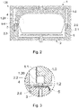
- the lower tool 2 comprises a base 2.1 below the support 2.0, the support 2.0 comprising a through hole 2.01 facing the actuation area 1.2 of the upper tool 1 and at least partially housing the rod 3.
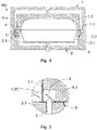
- the rod 3 is fixed to the base 2.1 and the support 2.0 is attached to the base 2.1 with freedom of vertical movement, by means of a spring 2.3 for example, between a standby position in which the rod 3 does not protrude above said support 2.0 towards the upper tool 1 ( Figures 2 and 3 ) and an actuation position in which the rod 3 at least partially protrudes above said support 2.0 ( Figures 4 and 5 ).
- the support 2.0 is arranged in the standby position while the sealing station 101 is in the open position, such that the rod 3 does not protrude from the support 2.0, which allows the tray 5 to be more readily positioned on said support 2.0.
- the sealing tool 1.0 does not exert pressure on the support 2.0 and is kept, as a result the support 2.0, in the standby position (without compressing the spring 2.3 and without the rod 3 protruding above the support 2.0).
- the sealing tool 1.0 moves downwards, there comes a time when it causes the integral movement of the support 2.0 from the standby position of said support 2.0 towards the actuation position in which said support 2.0 is arranged at a lower level with respect to its standby position.
- the sealing tool 1.0 presses the cover film 4 against the tray 5 which is supported on the support 2.0, sealing the cover film 4 to the tray 5.
- This downward movement of the support 2.0 causes the compression of the spring 2.3, such that the rod 3, by remaining fixed, protrudes at least partially above said support 2.0. and causes at least part of the cover film 4 facing the actuation area 1.2 of the upper tool 1 to move away from the cutting tool 1.1 once the cutting tool 1.1 has cut the cover film 4.
- the cutting tool 1.1 may comprise a relative movement with respect to the sealing tool 1.0: for example, the cutting tool 1.1 may be arranged lagging behind in its vertical path with respect to the sealing tool 1.0 such that the sealing tool 1.0 contacts the cover film 4 before the cutting tool 1.1 does, and when the sealing tool 1.0 continues to move, causing the downward movement of the support 2.0 and the sealing of the cover film 4 to the tray 5, the cutting tool 1.1 advances with respect to the sealing tool 1.0 for cutting said cover film 4 on said tray 5.
- the support 2.0 functions as a base 2.1, i.e., the support 2.0 can remain stationary.
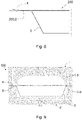
- the rod 3 at least partially protrudes above said support 2.0 at all times, and the cutting tool 1.1 may (or may not) comprise a relative movement with respect to the sealing tool 1.0 ( Figures 9 and 10 show a stationary support 2.0 and a cutting tool 1.1 fixed with respect to the sealing tool 1.0).
- the actuation area 1.2 of the upper tool 1 comprises a receiving cavity 1.20 so as to allow at least part of the cover film 4 facing said receiving cavity 1.20 to be raised, being separated from at least part of the tray 5, when the actuation means cause same to move away from the cutting tool 1.0.
- the separation of the cut end of the cover film 4 from the cutting tool 1.1 and from the tray 5 is thereby assured more readily and with greater certainty, which allows ensuring that said end is not sealed to said tray 5.
- the receiving cavity 1.20 furthermore functions as an opening configured for partially housing the rod 3.
- the rod 3 fixed to the lower tool 2 may comprise a cutting edge for making a cut in the tray 5, and thus facilitate acting on the cover film 4. This cutting edge would not be required if the tray 5 comprises a cut or hole facing the rod 3.
- the cutting edge of the rod 3 may have any desired shape (the vertex of a cone, a crescent shape, two sides of a triangle, three sides of a rectangle, etc.), for generating a cut in the tray 5 with said shape ( Figure 7 shows a crescent shape 3.1), but it would preferably not limit a closed contour (it would thus not define a circle, a complete triangle, or a complete rectangle, for example).
- the cutting edge may be accompanied by a surface of the rod 3 configured for pushing the tray 5 as it is cutting it.
- said rod 3 can be fixed to the upper tool 1 as occurs with the embodiment depicted in Figures 11 and 12 .
- the rod 3 is fixed to the sealing tool 1.0 of the upper tool 1 (although it could be fixed to the cutting tool 1.1), and said rod 3 does not comprise any cutting edge to avoid cutting the cover film 4.
- the actuation area 1.2 of the upper tool 1 comprises a receiving cavity 1.20 such as the one described above, and it would be particularly advantageous for the tray 5 to comprise a cut or hole facing the rod 3, or at least for the tray 5 to be made of a deformable material, so that the actuation of the rod 3 can introduce the cover film 4 at least into the opening of the lower tool 2 configured for partially housing the rod 3, thus causing the end of the cover film 4 which will be part of the package 200 to move away from the cutting tool 1.1 and to not adhere to the tray 5 as shown in Figure 12 .
- the actuation means instead of a rod 3 the actuation means comprise a suction device configured for causing a suction on the cover film 4 facing the actuation area 1.2 of the upper tool 1.
- the suction device is configured for generating the suction from the upper tool 1 and the upper tool 1 comprises a receiving cavity 1.20 such as the one described above.
- the suction causes part of the cover film 4 to be thus received in said receiving cavity 1.20.
- the suction device can be fixed and generate a suction for attracting the corresponding part of the cover film 4, although it could comprise an element such as a suction cup, for example, that is vertically movable along said receiving cavity 1.20, such that its movement causes the movement of said part of the cover film 4.
- the suction device is configured for generating the suction from the lower tool 2.
- a suction attracting the cover film 4 is generated, and to that end the tray 5 would comprise at least one hole affected by the suction, such that the cover film 4 arranged above said hole would be attracted by suction.
- the upper tool 1 could also comprise a receiving cavity 1.20.
- the lower tool 2 preferably comprises a receiving cavity facing the actuation area 1.2 of the upper tool 1, so as to allow the cover film 4 to be pulled.
- the hole of the tray 5 would be arranged on said receiving cavity.
- the actuation means comprise an injection device.
- the cover film 4 instead of cover film 4 being attracted, the cover film 4 would be pushed with an injection of gas (air, for example).
- the injection device is configured for performing the injection from the upper tool 1
- the lower tool 2 would comprise a receiving cavity for receiving the cover film 4 (the tray 5 would have a hole that said cover film 4 goes through).
- the upper tool 1 would comprise a receiving cavity for receiving the cover film 4 (the tray 5 would preferably have a hole to allow the passage of the gas towards the cover film 4).
Landscapes
- Engineering & Computer Science (AREA)
- Mechanical Engineering (AREA)
- Closing Of Containers (AREA)
Priority Applications (1)
| Application Number | Priority Date | Filing Date | Title |
|---|---|---|---|
| EP21382051.7A EP4032689A1 (fr) | 2021-01-22 | 2021-01-22 | Thermoscelleuse pour générer des emballages faciles à ouvrir |
Applications Claiming Priority (1)
| Application Number | Priority Date | Filing Date | Title |
|---|---|---|---|
| EP21382051.7A EP4032689A1 (fr) | 2021-01-22 | 2021-01-22 | Thermoscelleuse pour générer des emballages faciles à ouvrir |
Publications (1)
| Publication Number | Publication Date |
|---|---|
| EP4032689A1 true EP4032689A1 (fr) | 2022-07-27 |
Family
ID=74859385
Family Applications (1)
| Application Number | Title | Priority Date | Filing Date |
|---|---|---|---|
| EP21382051.7A Withdrawn EP4032689A1 (fr) | 2021-01-22 | 2021-01-22 | Thermoscelleuse pour générer des emballages faciles à ouvrir |
Country Status (1)
| Country | Link |
|---|---|
| EP (1) | EP4032689A1 (fr) |
Citations (3)
| Publication number | Priority date | Publication date | Assignee | Title |
|---|---|---|---|---|
| US20040206048A1 (en) * | 2003-04-17 | 2004-10-21 | Shikoku Kakoki Co., Ltd. | Apparatus for sealing containers |
| WO2016055598A1 (fr) * | 2014-10-10 | 2016-04-14 | Cryovac, Inc. | Appareil et procédé pour emballer un produit |
| US20190062032A1 (en) | 2017-08-30 | 2019-02-28 | Multivac Sepp Haggenmüller Se & Co. Kg | Sealing station and method for producing skin packaging with tear-off corner |
-
2021
- 2021-01-22 EP EP21382051.7A patent/EP4032689A1/fr not_active Withdrawn
Patent Citations (3)
| Publication number | Priority date | Publication date | Assignee | Title |
|---|---|---|---|---|
| US20040206048A1 (en) * | 2003-04-17 | 2004-10-21 | Shikoku Kakoki Co., Ltd. | Apparatus for sealing containers |
| WO2016055598A1 (fr) * | 2014-10-10 | 2016-04-14 | Cryovac, Inc. | Appareil et procédé pour emballer un produit |
| US20190062032A1 (en) | 2017-08-30 | 2019-02-28 | Multivac Sepp Haggenmüller Se & Co. Kg | Sealing station and method for producing skin packaging with tear-off corner |
Similar Documents
| Publication | Publication Date | Title |
|---|---|---|
| US20100024359A1 (en) | Packaging machine for the production of a packaging having a recess in the packaging cavity edge | |
| US5056292A (en) | Vacuum chamber packaging machine | |
| US9649807B2 (en) | Apparatus for forming and labeling an object and object so obtained | |
| NZ572814A (en) | Vacuum skin packaging apparatus and process | |
| GB1440922A (en) | Closure of containers | |
| EP4032689A1 (fr) | Thermoscelleuse pour générer des emballages faciles à ouvrir | |
| EP3733531B2 (fr) | Procédé et machine d'emballage de produits | |
| US6508047B1 (en) | Method and apparatus for capping container cans for food products and drinks | |
| JPH111203A (ja) | ストレッチフィルムによる包装装置及びその包装方法 | |
| US4072074A (en) | Device for forming orderly arranged groups of packages from a continuous web of packages | |
| JP7098202B2 (ja) | ブリスター容器の封緘方法および封緘構造 | |
| CN112810176A (zh) | 容器预切割系统 | |
| JP7096719B2 (ja) | フィルムのカット方法およびカット装置 | |
| JP2023091774A (ja) | 食品カップのパックに分離線を形成するためのツール | |
| JPH11314616A (ja) | ブリスター包装機 | |
| JP2006001579A (ja) | 袋切断用カッタ装置及びそれを組み込んだエンドシール・カッタ装置 | |
| JP7566446B1 (ja) | 給排気装置 | |
| KR200316342Y1 (ko) | 포장 봉투 절단용구 | |
| US3474591A (en) | Automatic packaging apparatus with removable die covering | |
| JP2024092253A (ja) | エア抜き装置 | |
| KR102032465B1 (ko) | 식품포장기의 포장용기 밀봉방법 | |
| CN211845537U (zh) | 一种液体密封包装袋 | |
| JP5976475B2 (ja) | 打抜き装置 | |
| JP2019081612A (ja) | 包装用容器の蓋 | |
| NL2025718B1 (nl) | Werkwijze en inrichting voor het uitbreken van een ponsfragment |
Legal Events
| Date | Code | Title | Description |
|---|---|---|---|
| PUAI | Public reference made under article 153(3) epc to a published international application that has entered the european phase |
Free format text: ORIGINAL CODE: 0009012 |
|
| STAA | Information on the status of an ep patent application or granted ep patent |
Free format text: STATUS: THE APPLICATION HAS BEEN PUBLISHED |
|
| AK | Designated contracting states |
Kind code of ref document: A1 Designated state(s): AL AT BE BG CH CY CZ DE DK EE ES FI FR GB GR HR HU IE IS IT LI LT LU LV MC MK MT NL NO PL PT RO RS SE SI SK SM TR |
|
| STAA | Information on the status of an ep patent application or granted ep patent |
Free format text: STATUS: REQUEST FOR EXAMINATION WAS MADE |
|
| 17P | Request for examination filed |
Effective date: 20230127 |
|
| RBV | Designated contracting states (corrected) |
Designated state(s): AL AT BE BG CH CY CZ DE DK EE ES FI FR GB GR HR HU IE IS IT LI LT LU LV MC MK MT NL NO PL PT RO RS SE SI SK SM TR |
|
| GRAP | Despatch of communication of intention to grant a patent |
Free format text: ORIGINAL CODE: EPIDOSNIGR1 |
|
| STAA | Information on the status of an ep patent application or granted ep patent |
Free format text: STATUS: GRANT OF PATENT IS INTENDED |
|
| RIC1 | Information provided on ipc code assigned before grant |
Ipc: B29C 65/78 20060101ALN20230531BHEP Ipc: B65B 61/18 20060101ALI20230531BHEP Ipc: B65B 61/06 20060101ALI20230531BHEP Ipc: B65B 51/14 20060101ALI20230531BHEP Ipc: B65B 7/16 20060101ALI20230531BHEP Ipc: B29C 65/76 20060101ALI20230531BHEP Ipc: B29C 65/74 20060101ALI20230531BHEP Ipc: B29C 65/02 20060101AFI20230531BHEP |
|
| INTG | Intention to grant announced |
Effective date: 20230616 |
|
| STAA | Information on the status of an ep patent application or granted ep patent |
Free format text: STATUS: THE APPLICATION IS DEEMED TO BE WITHDRAWN |
|
| 18D | Application deemed to be withdrawn |
Effective date: 20231027 |