EP4032732B1 - Luftfedersystem, fahrzeug und steuerungsverfahren - Google Patents
Luftfedersystem, fahrzeug und steuerungsverfahren Download PDFInfo
- Publication number
- EP4032732B1 EP4032732B1 EP21213324.3A EP21213324A EP4032732B1 EP 4032732 B1 EP4032732 B1 EP 4032732B1 EP 21213324 A EP21213324 A EP 21213324A EP 4032732 B1 EP4032732 B1 EP 4032732B1
- Authority
- EP
- European Patent Office
- Prior art keywords
- air
- air spring
- connecting pipeline
- spring
- vehicle
- Prior art date
- Legal status (The legal status is an assumption and is not a legal conclusion. Google has not performed a legal analysis and makes no representation as to the accuracy of the status listed.)
- Active
Links
Images




Classifications
-
- F—MECHANICAL ENGINEERING; LIGHTING; HEATING; WEAPONS; BLASTING
- F16—ENGINEERING ELEMENTS AND UNITS; GENERAL MEASURES FOR PRODUCING AND MAINTAINING EFFECTIVE FUNCTIONING OF MACHINES OR INSTALLATIONS; THERMAL INSULATION IN GENERAL
- F16F—SPRINGS; SHOCK-ABSORBERS; MEANS FOR DAMPING VIBRATION
- F16F15/00—Suppression of vibrations in systems; Means or arrangements for avoiding or reducing out-of-balance forces, e.g. due to motion
- F16F15/02—Suppression of vibrations of non-rotating, e.g. reciprocating systems; Suppression of vibrations of rotating systems by use of members not moving with the rotating systems
- F16F15/023—Suppression of vibrations of non-rotating, e.g. reciprocating systems; Suppression of vibrations of rotating systems by use of members not moving with the rotating systems using fluid means
- F16F15/027—Suppression of vibrations of non-rotating, e.g. reciprocating systems; Suppression of vibrations of rotating systems by use of members not moving with the rotating systems using fluid means comprising control arrangements
-
- B—PERFORMING OPERATIONS; TRANSPORTING
- B60—VEHICLES IN GENERAL
- B60G—VEHICLE SUSPENSION ARRANGEMENTS
- B60G11/00—Resilient suspensions characterised by arrangement, location or kind of springs
- B60G11/26—Resilient suspensions characterised by arrangement, location or kind of springs having fluid springs only, e.g. hydropneumatic springs
- B60G11/27—Resilient suspensions characterised by arrangement, location or kind of springs having fluid springs only, e.g. hydropneumatic springs wherein the fluid is a gas
-
- B—PERFORMING OPERATIONS; TRANSPORTING
- B60—VEHICLES IN GENERAL
- B60G—VEHICLE SUSPENSION ARRANGEMENTS
- B60G17/00—Resilient suspensions having means for adjusting the spring or vibration-damper characteristics, for regulating the distance between a supporting surface and a sprung part of vehicle or for locking suspension during use to meet varying vehicular or surface conditions, e.g. due to speed or load
- B60G17/015—Resilient suspensions having means for adjusting the spring or vibration-damper characteristics, for regulating the distance between a supporting surface and a sprung part of vehicle or for locking suspension during use to meet varying vehicular or surface conditions, e.g. due to speed or load the regulating means comprising electric or electronic elements
- B60G17/0152—Resilient suspensions having means for adjusting the spring or vibration-damper characteristics, for regulating the distance between a supporting surface and a sprung part of vehicle or for locking suspension during use to meet varying vehicular or surface conditions, e.g. due to speed or load the regulating means comprising electric or electronic elements characterised by the action on a particular type of suspension unit
- B60G17/0155—Resilient suspensions having means for adjusting the spring or vibration-damper characteristics, for regulating the distance between a supporting surface and a sprung part of vehicle or for locking suspension during use to meet varying vehicular or surface conditions, e.g. due to speed or load the regulating means comprising electric or electronic elements characterised by the action on a particular type of suspension unit pneumatic unit
-
- B—PERFORMING OPERATIONS; TRANSPORTING
- B60—VEHICLES IN GENERAL
- B60G—VEHICLE SUSPENSION ARRANGEMENTS
- B60G17/00—Resilient suspensions having means for adjusting the spring or vibration-damper characteristics, for regulating the distance between a supporting surface and a sprung part of vehicle or for locking suspension during use to meet varying vehicular or surface conditions, e.g. due to speed or load
- B60G17/015—Resilient suspensions having means for adjusting the spring or vibration-damper characteristics, for regulating the distance between a supporting surface and a sprung part of vehicle or for locking suspension during use to meet varying vehicular or surface conditions, e.g. due to speed or load the regulating means comprising electric or electronic elements
- B60G17/016—Resilient suspensions having means for adjusting the spring or vibration-damper characteristics, for regulating the distance between a supporting surface and a sprung part of vehicle or for locking suspension during use to meet varying vehicular or surface conditions, e.g. due to speed or load the regulating means comprising electric or electronic elements characterised by their responsiveness, when the vehicle is travelling, to specific motion, a specific condition, or driver input
- B60G17/0162—Resilient suspensions having means for adjusting the spring or vibration-damper characteristics, for regulating the distance between a supporting surface and a sprung part of vehicle or for locking suspension during use to meet varying vehicular or surface conditions, e.g. due to speed or load the regulating means comprising electric or electronic elements characterised by their responsiveness, when the vehicle is travelling, to specific motion, a specific condition, or driver input mainly during a motion involving steering operation, e.g. cornering, overtaking
-
- B—PERFORMING OPERATIONS; TRANSPORTING
- B60—VEHICLES IN GENERAL
- B60G—VEHICLE SUSPENSION ARRANGEMENTS
- B60G17/00—Resilient suspensions having means for adjusting the spring or vibration-damper characteristics, for regulating the distance between a supporting surface and a sprung part of vehicle or for locking suspension during use to meet varying vehicular or surface conditions, e.g. due to speed or load
- B60G17/015—Resilient suspensions having means for adjusting the spring or vibration-damper characteristics, for regulating the distance between a supporting surface and a sprung part of vehicle or for locking suspension during use to meet varying vehicular or surface conditions, e.g. due to speed or load the regulating means comprising electric or electronic elements
- B60G17/016—Resilient suspensions having means for adjusting the spring or vibration-damper characteristics, for regulating the distance between a supporting surface and a sprung part of vehicle or for locking suspension during use to meet varying vehicular or surface conditions, e.g. due to speed or load the regulating means comprising electric or electronic elements characterised by their responsiveness, when the vehicle is travelling, to specific motion, a specific condition, or driver input
- B60G17/0165—Resilient suspensions having means for adjusting the spring or vibration-damper characteristics, for regulating the distance between a supporting surface and a sprung part of vehicle or for locking suspension during use to meet varying vehicular or surface conditions, e.g. due to speed or load the regulating means comprising electric or electronic elements characterised by their responsiveness, when the vehicle is travelling, to specific motion, a specific condition, or driver input to an external condition, e.g. rough road surface, side wind
-
- B—PERFORMING OPERATIONS; TRANSPORTING
- B60—VEHICLES IN GENERAL
- B60G—VEHICLE SUSPENSION ARRANGEMENTS
- B60G17/00—Resilient suspensions having means for adjusting the spring or vibration-damper characteristics, for regulating the distance between a supporting surface and a sprung part of vehicle or for locking suspension during use to meet varying vehicular or surface conditions, e.g. due to speed or load
- B60G17/02—Spring characteristics, e.g. mechanical springs and mechanical adjusting means
- B60G17/04—Spring characteristics, e.g. mechanical springs and mechanical adjusting means fluid spring characteristics
- B60G17/052—Pneumatic spring characteristics
- B60G17/0523—Regulating distributors or valves for pneumatic springs
- B60G17/0525—Height adjusting or levelling valves
-
- B—PERFORMING OPERATIONS; TRANSPORTING
- B60—VEHICLES IN GENERAL
- B60G—VEHICLE SUSPENSION ARRANGEMENTS
- B60G21/00—Interconnection systems for two or more resiliently-suspended wheels, e.g. for stabilising a vehicle body with respect to acceleration, deceleration or centrifugal forces
- B60G21/02—Interconnection systems for two or more resiliently-suspended wheels, e.g. for stabilising a vehicle body with respect to acceleration, deceleration or centrifugal forces permanently interconnected
- B60G21/06—Interconnection systems for two or more resiliently-suspended wheels, e.g. for stabilising a vehicle body with respect to acceleration, deceleration or centrifugal forces permanently interconnected fluid
- B60G21/067—Interconnection systems for two or more resiliently-suspended wheels, e.g. for stabilising a vehicle body with respect to acceleration, deceleration or centrifugal forces permanently interconnected fluid between wheels on different axles on the same side of the vehicle, i.e. the left or the right side
-
- B—PERFORMING OPERATIONS; TRANSPORTING
- B60—VEHICLES IN GENERAL
- B60G—VEHICLE SUSPENSION ARRANGEMENTS
- B60G21/00—Interconnection systems for two or more resiliently-suspended wheels, e.g. for stabilising a vehicle body with respect to acceleration, deceleration or centrifugal forces
- B60G21/02—Interconnection systems for two or more resiliently-suspended wheels, e.g. for stabilising a vehicle body with respect to acceleration, deceleration or centrifugal forces permanently interconnected
- B60G21/06—Interconnection systems for two or more resiliently-suspended wheels, e.g. for stabilising a vehicle body with respect to acceleration, deceleration or centrifugal forces permanently interconnected fluid
- B60G21/073—Interconnection systems for two or more resiliently-suspended wheels, e.g. for stabilising a vehicle body with respect to acceleration, deceleration or centrifugal forces permanently interconnected fluid between wheels on the same axle but on different sides of the vehicle, i.e. the left and right wheel suspensions being interconnected
-
- F—MECHANICAL ENGINEERING; LIGHTING; HEATING; WEAPONS; BLASTING
- F16—ENGINEERING ELEMENTS AND UNITS; GENERAL MEASURES FOR PRODUCING AND MAINTAINING EFFECTIVE FUNCTIONING OF MACHINES OR INSTALLATIONS; THERMAL INSULATION IN GENERAL
- F16F—SPRINGS; SHOCK-ABSORBERS; MEANS FOR DAMPING VIBRATION
- F16F15/00—Suppression of vibrations in systems; Means or arrangements for avoiding or reducing out-of-balance forces, e.g. due to motion
- F16F15/02—Suppression of vibrations of non-rotating, e.g. reciprocating systems; Suppression of vibrations of rotating systems by use of members not moving with the rotating systems
- F16F15/023—Suppression of vibrations of non-rotating, e.g. reciprocating systems; Suppression of vibrations of rotating systems by use of members not moving with the rotating systems using fluid means
-
- B—PERFORMING OPERATIONS; TRANSPORTING
- B60—VEHICLES IN GENERAL
- B60G—VEHICLE SUSPENSION ARRANGEMENTS
- B60G2202/00—Indexing codes relating to the type of spring, damper or actuator
- B60G2202/10—Type of spring
- B60G2202/15—Fluid spring
- B60G2202/152—Pneumatic spring
-
- B—PERFORMING OPERATIONS; TRANSPORTING
- B60—VEHICLES IN GENERAL
- B60G—VEHICLE SUSPENSION ARRANGEMENTS
- B60G2202/00—Indexing codes relating to the type of spring, damper or actuator
- B60G2202/40—Type of actuator
- B60G2202/41—Fluid actuator
- B60G2202/412—Pneumatic actuator
-
- B—PERFORMING OPERATIONS; TRANSPORTING
- B60—VEHICLES IN GENERAL
- B60G—VEHICLE SUSPENSION ARRANGEMENTS
- B60G2202/00—Indexing codes relating to the type of spring, damper or actuator
- B60G2202/40—Type of actuator
- B60G2202/41—Fluid actuator
- B60G2202/416—Fluid actuator using a pump, e.g. in the line connecting the lower chamber to the upper chamber of the actuator
-
- B—PERFORMING OPERATIONS; TRANSPORTING
- B60—VEHICLES IN GENERAL
- B60G—VEHICLE SUSPENSION ARRANGEMENTS
- B60G2204/00—Indexing codes related to suspensions per se or to auxiliary parts
- B60G2204/80—Interactive suspensions; arrangement affecting more than one suspension unit
- B60G2204/81—Interactive suspensions; arrangement affecting more than one suspension unit front and rear unit
-
- B—PERFORMING OPERATIONS; TRANSPORTING
- B60—VEHICLES IN GENERAL
- B60G—VEHICLE SUSPENSION ARRANGEMENTS
- B60G2204/00—Indexing codes related to suspensions per se or to auxiliary parts
- B60G2204/80—Interactive suspensions; arrangement affecting more than one suspension unit
- B60G2204/82—Interactive suspensions; arrangement affecting more than one suspension unit left and right unit on same axle
-
- B—PERFORMING OPERATIONS; TRANSPORTING
- B60—VEHICLES IN GENERAL
- B60G—VEHICLE SUSPENSION ARRANGEMENTS
- B60G2204/00—Indexing codes related to suspensions per se or to auxiliary parts
- B60G2204/80—Interactive suspensions; arrangement affecting more than one suspension unit
- B60G2204/83—Type of interconnection
- B60G2204/8304—Type of interconnection using a fluid
-
- B—PERFORMING OPERATIONS; TRANSPORTING
- B60—VEHICLES IN GENERAL
- B60G—VEHICLE SUSPENSION ARRANGEMENTS
- B60G2400/00—Indexing codes relating to detected, measured or calculated conditions or factors
- B60G2400/05—Attitude
- B60G2400/051—Angle
- B60G2400/0511—Roll angle
-
- B—PERFORMING OPERATIONS; TRANSPORTING
- B60—VEHICLES IN GENERAL
- B60G—VEHICLE SUSPENSION ARRANGEMENTS
- B60G2400/00—Indexing codes relating to detected, measured or calculated conditions or factors
- B60G2400/20—Speed
- B60G2400/204—Vehicle speed
-
- B—PERFORMING OPERATIONS; TRANSPORTING
- B60—VEHICLES IN GENERAL
- B60G—VEHICLE SUSPENSION ARRANGEMENTS
- B60G2400/00—Indexing codes relating to detected, measured or calculated conditions or factors
- B60G2400/25—Stroke; Height; Displacement
- B60G2400/252—Stroke; Height; Displacement vertical
-
- B—PERFORMING OPERATIONS; TRANSPORTING
- B60—VEHICLES IN GENERAL
- B60G—VEHICLE SUSPENSION ARRANGEMENTS
- B60G2400/00—Indexing codes relating to detected, measured or calculated conditions or factors
- B60G2400/40—Steering conditions
- B60G2400/41—Steering angle
-
- B—PERFORMING OPERATIONS; TRANSPORTING
- B60—VEHICLES IN GENERAL
- B60G—VEHICLE SUSPENSION ARRANGEMENTS
- B60G2400/00—Indexing codes relating to detected, measured or calculated conditions or factors
- B60G2400/50—Pressure
- B60G2400/51—Pressure in suspension unit
- B60G2400/512—Pressure in suspension unit in spring
- B60G2400/5122—Fluid spring
- B60G2400/51222—Pneumatic
-
- B—PERFORMING OPERATIONS; TRANSPORTING
- B60—VEHICLES IN GENERAL
- B60G—VEHICLE SUSPENSION ARRANGEMENTS
- B60G2500/00—Indexing codes relating to the regulated action or device
- B60G2500/20—Spring action or springs
- B60G2500/202—Height or leveling valve for air-springs
- B60G2500/2021—Arrangement of valves
-
- B—PERFORMING OPERATIONS; TRANSPORTING
- B60—VEHICLES IN GENERAL
- B60G—VEHICLE SUSPENSION ARRANGEMENTS
- B60G2500/00—Indexing codes relating to the regulated action or device
- B60G2500/30—Height or ground clearance
- B60G2500/32—Height or ground clearance of only one vehicle part or side
- B60G2500/322—Height or ground clearance of only one vehicle part or side only front part
-
- B—PERFORMING OPERATIONS; TRANSPORTING
- B60—VEHICLES IN GENERAL
- B60G—VEHICLE SUSPENSION ARRANGEMENTS
- B60G2500/00—Indexing codes relating to the regulated action or device
- B60G2500/30—Height or ground clearance
- B60G2500/32—Height or ground clearance of only one vehicle part or side
- B60G2500/324—Height or ground clearance of only one vehicle part or side only rear part
-
- B—PERFORMING OPERATIONS; TRANSPORTING
- B60—VEHICLES IN GENERAL
- B60G—VEHICLE SUSPENSION ARRANGEMENTS
- B60G2500/00—Indexing codes relating to the regulated action or device
- B60G2500/30—Height or ground clearance
- B60G2500/32—Height or ground clearance of only one vehicle part or side
- B60G2500/326—Height or ground clearance of only one vehicle part or side only left or right side
-
- B—PERFORMING OPERATIONS; TRANSPORTING
- B60—VEHICLES IN GENERAL
- B60G—VEHICLE SUSPENSION ARRANGEMENTS
- B60G2600/00—Indexing codes relating to particular elements, systems or processes used on suspension systems or suspension control systems
- B60G2600/02—Retarders, delaying means, dead zones, threshold values, cut-off frequency, timer interruption
-
- B—PERFORMING OPERATIONS; TRANSPORTING
- B60—VEHICLES IN GENERAL
- B60G—VEHICLE SUSPENSION ARRANGEMENTS
- B60G2800/00—Indexing codes relating to the type of movement or to the condition of the vehicle and to the end result to be achieved by the control action
- B60G2800/01—Attitude or posture control
- B60G2800/012—Rolling condition
-
- B—PERFORMING OPERATIONS; TRANSPORTING
- B60—VEHICLES IN GENERAL
- B60G—VEHICLE SUSPENSION ARRANGEMENTS
- B60G2800/00—Indexing codes relating to the type of movement or to the condition of the vehicle and to the end result to be achieved by the control action
- B60G2800/01—Attitude or posture control
- B60G2800/012—Rolling condition
- B60G2800/0124—Roll-over conditions
-
- B—PERFORMING OPERATIONS; TRANSPORTING
- B60—VEHICLES IN GENERAL
- B60G—VEHICLE SUSPENSION ARRANGEMENTS
- B60G2800/00—Indexing codes relating to the type of movement or to the condition of the vehicle and to the end result to be achieved by the control action
- B60G2800/24—Steering, cornering
Definitions
- the present disclosure relates to the field of automobile technology, and in particular, relates to an air spring system, a vehicle, and a control method.
- Air springs have the advantages such as inverse S nonlinear stiffness, low vibration transmission rate, and good sound insulation performance, and thus they are widely applied in automotive suspensions.
- the existing air suspensions are mainly used to solve the problems in terms of vehicle height adjustment and vertical vibration reduction.
- the air spring has a slow response to dangerous conditions such as collision, high-speed cornering or slippery road surface, and the active safety problem cannot be solved well.
- US 3356 954 A discloses a wheel suspension system for vehicle.
- WO 2018/141049 A1 provides an active suspension control system and method for individually controlling a suspension assembly of each wheel of a vehicle in response to driving conditions.
- Embodiments of the present disclosure provide an air spring system, a vehicle, and a control method.
- An embodiment of the present disclosure provides an air spring system for a vehicle.
- the air spring system includes a plurality of air springs, an air supply pipeline, a pressure accumulator, and a plurality of multi-way valves.
- Each of the plurality of air springs is disposed to correspond to a suspension of the vehicle, and has a first air port and a second air port.
- the pressure accumulator is disposed on the air supply pipeline and configured to supply air pressure to each of the plurality of air springs through the first air port and the second air port.
- the plurality of multi-way valves is configured to connect the plurality of air springs with the air supply pipeline and corresponds to the plurality of air springs in one-to-one correspondence.
- the first air port of one of the plurality of air springs corresponding to the multi-way valve is connected to the air supply pipeline through the multi-way valve, and the second air port of the air spring is connected to the atmosphere through the multi-way valve, and the air spring ascends under air supply of the pressure accumulator; and when the multi-way valve is in a second state, the first air port of the air spring corresponding to the multi-way valve is connected to the atmosphere through the multi-way valve, and the second air port of the air spring is connected to the air supply pipeline through the multi-way valve, and the air spring descends under air supply of the pressure accumulator.
- the air spring system includes a control valve configured to be connected to the pressure accumulator to control an on/off state of the pressure accumulator.
- the air spring system further includes an air pump connected to the air supply pipeline and configured to supply air to the plurality of air springs through the plurality of multi-way valves and to fill air into the pressure accumulator.
- An embodiment of the present disclosure provides a vehicle including the air spring system as described above.
- the plurality of air springs includes a first air spring configured to be disposed on a left front wheel of the vehicle, a second air spring configured to be disposed on a left rear wheel of the vehicle, a third air spring configured to be disposed on a right front wheel of the vehicle, and a fourth air spring configured to be disposed on a right rear wheel of the vehicle; and the plurality of multi-way valves includes a first multi-way valve configured to connect the first air spring with the air supply pipeline, a second multi-way valve configured to connect the second air spring with the air supply pipeline, a third multi-way valve configured to connect the third air spring with the air supply pipeline, and a fourth multi-way valve configured to connect the fourth air spring with the air supply pipeline.
- the air spring system further includes a first connecting pipeline, a second connecting pipeline, a third connecting pipeline, a fourth connecting pipeline, a first pass valve disposed on the first connecting pipeline, a second pass valve disposed on the second connecting pipeline, a third pass valve disposed on the third connecting pipeline, and a fourth pass valve disposed on the fourth connecting pipeline; and one end of the first connecting pipeline is connected to the first air port of the first air spring, and the other end of the first connecting pipeline is connected to the second air port of the second air spring; one end of the second connecting pipeline is connected to the second air port of the second air spring, and the other end of the second connecting pipeline is connected to the first air port of the fourth air spring; one end of the third connecting pipeline is connected to the first air port of the third air spring, and the other end of the third connecting pipeline is connected to the second air port of the fourth air spring; and one end of the fourth connecting pipeline is connected to the first air port of the third air spring, and the other end of the fourth connecting pipeline is connected to the second air port of the first air port of the
- the first multi-way valve, the second multi-way valve, the third multi-way valve, and the fourth multi-way valve when a front side, a left side or a right side of the vehicle approaches a target object, among the first multi-way valve, the second multi-way valve, the third multi-way valve, and the fourth multi-way valve, two multi-way valves close to the target object are in a first state, the other two multi-way valvess are in a third state, and the first pass valve, the second pass valve, the third pass valve, and the fourth pass valve are all in a cut-off state; among the first air spring, the second air spring, the third air spring, and the fourth air spring, the first air ports and the second air ports of two air springs corresponding to the other two multi-way valves in the third state are isolated from the pressure accumulator, and states of the two air springs remain unchanged, and the other two air springs close to the target object are capable of ascending under the air supply of the pressure accumulator.
- the first multi-way valve, the second multi-way valve, the third multi-way valve, and the fourth multi-way valve when an angle of turning of the vehicle is greater than a preset angle and a vehicle speed of the vehicle is greater than a preset speed, among the first multi-way valve, the second multi-way valve, the third multi-way valve, and the fourth multi-way valve, two multi-way valves corresponding to a direction of the turning of the vehicle are in a second state, the other two multi-way valves are in the first state; the first pass valve and the third pass valve are in a cut-off state, and the second pass valve and the fourth pass valve are in a connected state; among the first air spring, the second air spring, the third air spring, and the fourth air spring, two air springs corresponding to the two multi-way valves in the second state are isolated from the pressure accumulator with the first air ports and the second air ports thereof and are capable of descending under the air supply of the pressure accumulator, and the other two air springs are capable of ascending under
- each of the plurality of multi-way valves when the vehicle is in a bumpy state, each of the plurality of multi-way valves is in a third state; the second pass valve and the fourth pass valve are in a cut-off state, the first pass valve and the third pass valve are in a connected state; the first air port of the first air spring is connected to the second air port of the second air spring through the first connecting pipeline, and the first air port of the third air spring is connected to the second air port of the fourth air spring through the third connecting pipeline.
- each of the plurality of multi-way valves when a number of turnings of the vehicle within a predetermined time period is greater than a preset number, each of the plurality of multi-way valves is in a third state; the first pass valve and the third pass valve are in a cut-off state, and the second pass valve and the fourth pass valve are in a connected state; the second air port of the first air spring is connected to the second air port of the third air spring through the fourth connecting pipeline, and the second air port of the second air spring is connected to the first air port of the fourth air spring through the second connecting pipeline.
- the first multi-way valve, the second multi-way valve, the third multi-way valve, and the fourth multi-way valve when a rear side of the vehicle approaches a target object, among the first multi-way valve, the second multi-way valve, the third multi-way valve, and the fourth multi-way valve, two multi-way valves close to the target object are in a second state, the other two multi-way valves are in a third state; the first pass valve, the second pass valve, the third pass valve, and the fourth pass valve are all in a cut-off state; among the first air spring, the second air spring, the third air spring, and the fourth air spring, two air spring corresponding to the two multi-way valves in the second state are isolated from the pressure accumulator with the first air ports and the second air ports thereof and are capable of descending under the air supply of the pressure accumulator, and states of the other two air springs remain unchanged.
- the vehicle further includes a body.
- Said air spring system is disposed on the body.
- An embodiment of the present disclosure provides a control method.
- the control method includes: controlling one of the plurality of multi-way valves to be in a first state to connect the first air port of one of the plurality of air springs corresponding to the multi-way valve to the air supply pipeline through the multi-way valve, and to connect the second air port of the air spring to the atmosphere through the multi-way valve; controlling the pressure accumulator to work to allow the air spring corresponding to the multi-way valve to ascend under air supply of the pressure accumulator when the multi-way valve is in the first state; controlling one of the plurality of multi-way valves to be in a second state to connect the first air port of one of the plurality of air springs corresponding to the multi-way valve to the atmosphere through the multi-way valve, and to connect the second air port of the air spring to the air supply pipeline through the multi-way valve; and when the multi-way valve is in the second state, controlling the pressure accumulator to work to allow the air spring corresponding to the multi-way valve to descend under the air
- the control method includes: when a front side, a left side or a right side of the vehicle approaches a target object, among the first multi-way valve, the second multi-way valve, the third multi-way valve, and the fourth multi-way valve, controlling two multi-way valves close to the target object to be in the first state, and controlling the other two multi-way valves to be in a third state, where among the first air spring, the second air spring, the third air spring, and the fourth air spring, the first air ports and the second air ports of two air spring corresponding to the other two multi-way valves in the third state are isolated from the pressure accumulator; controlling the first pass valve, the second pass valve, the third pass valve and the fourth pass valve to be in a cut-off state; and controlling the pressure accumulator to work to allow the other two air springs close the target object to ascend under the air supply of the pressure accumulator, and to allow states of the two air springs corresponding to the other two multi-way valves in the third state to remain unchanged.
- control method further includes: when an angle of turning of the vehicle is greater than a preset angle and a vehicle speed of the vehicle is greater than a preset speed, among the first multi-way valve, the second multi-way valve, the third multi-way valve, and the fourth multi-way valve, controlling two multi-way valves corresponding to a direction of the turning of the vehicle to be in a second state, and controlling the other two multi-way valves to be in the first state, wherein the first air ports and the second air ports of two air springs corresponding to the two multi-way valves in the second state are isolated from the pressure accumulator; controlling the first pass valve and the third pass valve to be in a cut-off state, and controlling the second pass valve and the fourth pass valve to be in a connected state; and controlling the pressure accumulator to work to allow two air springs corresponding to the two multi-way valves in the second state to descend under air supply of the pressure accumulator, and to allow the other two air springs to ascend under air supply of the pressure
- control method further includes: when the vehicle is in a bumpy state, controlling each of the plurality of multi-way valves to be in a third state; and controlling the second pass valve and the fourth pass valve to be in a cut-off state, and controlling the first pass valve and the third pass valve to be in a connected state, wherein the first air port of the first air spring is connected to the second air port of the second air spring through the first connecting pipeline, and the first air port of the third air spring is connected to the second air port of the fourth air spring through the third connecting pipeline.
- control method includes: when a number of turnings of the vehicle within a predetermined time period is greater than a preset number, controlling all of the plurality of multi-way valves to be in a third state; and controlling the first pass valve and the third pass valve to be in a cut-off state, and controlling the second pass valve and the fourth pass valve to be in a connected state, wherein the second air port of the first air spring is connected to the second air port of the third air spring through the fourth connecting pipeline, and the second air port of the second air spring is connected to the first air port of the fourth air spring through the second connecting pipeline.
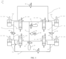
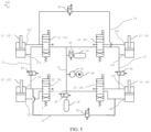
- Air spring system 100 air spring 10, first air spring 11, first air port 111 of first air spring 11, second air port 112 of first air spring 11, second air spring 12, first air port 121 of second air spring 12, second air port 122 of the second air spring 12, third air spring 13, first air port 131 of third air spring 13, second air port 132 of third air spring 13, fourth air spring 14, first air port 141 of fourth air spring 14, second air port 142 of fourth air spring 14, pressure accumulator 20, air supply pipeline 21, multi-way valve 30, first multi-way valve 31, second multi-way valve 32, third multi-way valve 33, fourth multi-way valve 34, control valve 40, air pump 50, motor 60, first connecting pipeline 71, second connecting pipeline 72, third connecting pipeline 73, fourth connecting pipeline 74, first pass valve 81, second pass valve 82, third pass valve 83, fourth pass valve 84, sensor 91, controller 92, vehicle 1000, body 200
- an embodiment of the present disclosure provides an air spring system 100 for a vehicle 1000.
- the air spring system 100 includes a plurality of air springs 10, a plurality of pressure accumulators 20, and a plurality of multi-way valves 30.
- Each air spring 10 is disposed to correspond to one suspension of the vehicle 1000.
- Each air spring 10 has a first air port and a second air port.
- the pressure accumulator 20 is disposed on an air supply pipeline 21 of the air spring system 100 and is configured to provide air pressure to the air spring 10 through the first air port and the second air port of the air spring 10.
- the multi-way valves 30 connect the air springs 10 and the air supply pipeline 21.
- the multi-way valves 30 When the multi-way valves 30 are in a first state, the first air ports of the air springs 10 are connected to the air supply pipeline 21 through the multi-way valves 30, and the second air ports of the air springs 10 are connected to the atmosphere through the multi-way valves 30, so that the air springs 10 can ascend under the air supply of the pressure accumulators 20.
- the multi-way valves 30 are in the second state, the first air ports of the air springs 10 are connected to the atmosphere through the multi-way valves 30, and the second air ports of the air spring 10 are connected to the air supply pipeline 21 through the multi-way valves 30, so that the air springs 10 can descend under the air supply of the pressure accumulators 20.
- the air springs 10 can respond quickly to solve the active safety problem.
- the air spring system 100 may include control valves 40.
- the control valve 40 is configured to connect the pressure accumulator 20 with the air supply pipeline 21. In this way, the control valve 40 can control the on/off state of the pressure accumulator 20.
- the air spring system 100 may include an air pump 50 and a motor 60.
- the motor 60 is connected to the air pump 50.
- the air pump 50 is connected to the air supply pipeline 21. In this way, when the motor 60 operates, the motor 60 can drive the air pump 50 to increase the air pressure, and the air pump 50 can supply air to the air spring 10 through the multi-way valve 30 and can also inflate the pressure accumulator 20.
- the plurality of air springs 10 may include a first air spring 11, a second air spring 12, a third air spring 13, and a fourth air spring 14.
- the first air spring 11 is configured to be installed on a left front wheel of the vehicle 1000.
- the second air spring 12 is configured to be installed on a left rear wheel of the vehicle 1000.
- the third air spring 13 is configured to be installed on a right front wheel of the vehicle 1000.
- the fourth air spring 14 is configured to be installed on a right rear wheel of the vehicle 1000.
- the multi-way valves 30 may include a first multi-way valve 31, a second multi-way valve 32, a third multi-way valve 33, and a fourth multi-way valve 34.
- the first multi-way valve 31 connects the first air spring 11 with the air supply pipeline 21
- the second multi-way valve 32 connects the second air spring 12 with the air supply pipeline 21
- the third multi-way valve 33 connects the third air spring. 13 with the air supply pipeline 21
- the fourth multi-way valve 34 connects the fourth air spring 14 with the air supply pipeline 21.
- the air pump 50 and the pressure accumulator 20 can supply air to the air springs 10 through the air supply pipeline 21 and the multi-way valves 30, so as to change the state of the air springs 10.
- the air spring system 100 includes a first connecting pipeline 71, a second connecting pipeline 72, a third connecting pipeline 73, a fourth connecting pipeline 74, a first way wave 81, a second pass valve 82, a third pass valve 83, and a fourth pass valve 84.
- the first pass valve 81 is provided on the first connecting pipeline 71
- the second pass valve 82 is provided on the second connecting pipeline 72
- the third pass valve 83 is provided on the third connecting pipeline 73
- the fourth pass valve 84 is provided on the fourth connecting pipeline 74.
- one end of the first connecting pipeline 71 is connected to the first air port 111 of the first air spring 11, and the other end connected to the second air port 122 of the second air spring 12;
- one end of the second connecting pipeline 72 is connected to the second air port 122 of the second air spring 12, and the other end thereof is connected to the first air port 141 of the fourth air spring 14;
- one end of the third connecting pipeline 73 is connected to the first air port 131 of the third air spring 13, and the other end thereof is connected to the second air port 142 of the fourth air spring 14;
- one end of the fourth connecting pipeline 74 is connected to the first air port 131 of the third air spring 13, and the other end thereof is connected to the second air port 112 of the first air spring 11.
- the air pump 50 and the pressure accumulators 20 can supply air to the air springs 10 through the first connecting pipeline 71, the second connecting pipeline 72, the third connecting pipeline 73, the fourth connecting pipeline 74, the first pass valve 81, the second pass valve 82, the third pass valve 83, and the fourth pass valve 84, so as to change the state of the air springs 10.
- the first air ports and the second air ports of the air springs 10 are isolated from the pressure accumulators 20. As such, the pressure accumulators 20 cannot directly supply air to the air springs 10 through the multi-way valves 30.
- the air spring system 100 may include a sensor 91 and a controller 92.
- the sensor 91 may include an air pressure sensor 91, a vehicle speed sensor 91, a tilt sensor 91 of the body 200, and a height sensor 91 of the body 200, etc., which is not limited in the embodiments of the present disclosure.
- the sensor 91 can detect a current state of the vehicle 1000 and transmit the signal to the controller 92 in real time, and the controller 92 can receive the signal of the sensor 91 and control the air spring system 100.
- the senor 91 detects the current state of the vehicle 1000 and transmits the state information to the controller 92 in real time, and thus the controller 92 can adjust the state of the air spring system 100 based on the current state of the vehicle 1000, so as to adapt the vehicle 1000 to the current state.
- the first multi-way valve 31 and the third multi-way valve 33 are both in the first state
- the second multi-way valve 32 and the fourth multi-way valve 34 are both in the third state.
- the first pass valve 81, the second pass valve 82, the third pass valve 83, and the fourth pass valve 84 are all in a cut-off state.
- the control valve 40 is in a connected state.
- the sensor 91 detects that the front side of the vehicle 1000 approaches the target object, the sensor 91 transmits this information to the controller 92.
- the motor 60 starts to work and drives the air pump 50 to increase the air pressure.
- the control valve 40 Since the control valve 40 is in the connected state, the pressure accumulator 20 and the air pump 50 supply air to the first air spring 11 through the first multi-way valve 31 and the first air port 111 of the first air spring 11, so that the first air spring 11 ascends rapidly under the air supply of the pressure accumulator 20 and the air pump 50; the pressure accumulator 20 and the air pump 50 supply air to the third air spring 13 through the third multi-way valve 33 and the first air port 131 of the third air spring 13, so that the third air spring 13 ascend rapidly under the air supply of the pressure accumulator 20 and the air pump 50.
- the second multi-way valve 32 and the fourth multi-way valve 34 are both in the third state, and the second pass valve 82 is in the cut-off state, the pressure accumulator 20 and the air pump 50 cannot supply air to the second air spring 12 and the fourth air spring 14, and thus the states of the second air spring 12 and the fourth air spring 14 remain unchanged.
- the sensor 91 detects that the front side of the vehicle 1000 approaches the target object, the rapid ascending of the first air spring 11 and the third air spring 13 can lower the risk of the driver, and the cooperation of the pressure accumulators 20 and the air pump 50 can increase the response speed and guarantee personal safety during emergency avoidance of obstacles.
- the two multi-way valves 30 corresponding to the rear side of the vehicle 1000 are in the first state, and the other two multi-way valves 30 are in the third state.
- the second multi-way valve 32 and the fourth multi-way valve 34 are both in the second state, and the first multi-way valve 31 and the third multi-way valve 33 are both in the third state.
- the first pass valve 81, the second pass valve 82, the third pass valve 83, and the fourth pass valve 84 are all in the cut-off state.
- the control valves 40 are in the connected state.
- the sensor 91 detects that the rear side of the vehicle 1000 approaches the target object, the sensor 91 transmits this information to the controller 92.
- the motor 60 starts to work and drives the air pump 50 to increase the air pressure. Since the control valves 40 are in the connected state, the pressure accumulator 20 and the air pump 50 can supply air to the second air spring 12 through the second multi-way valve 32 and the second air port 122 of the second air spring 12, so that the second air spring 12 descends rapidly under the air supply of the pressure accumulator 20 and the air pump 50; and the pressure accumulator 20 and the air pump 50 supply air to the fourth air spring 14 through the fourth multi-way valve 34 and the second air port 142 of the fourth air spring 14, so that the fourth air spring 14 descends rapidly under the air supply of the pressure accumulators 20 and the air pump 50.
- the fourth pass valve 84 Since the first multi-way valve 31 and the third multi-way valve 33 are both in the third state, and the fourth pass valve 84 is in the cut-off state, the pressure accumulator 20 and the air pumps 50 cannot supply air to the first air spring 11 and the third air spring 13, and thus the states of the first air spring 11 and the third air spring 13 remain unchanged.
- the second air spring 12 and the fourth air spring 14 corresponding to the rear side of the vehicle 1000 descend rapidly, which can reduce the risk of turnover of the vehicle 1000, and can increase the response speed and improve the driving safety during emergency avoidance of obstacles through the cooperation of the pressure accumulator 20 and the air pump 50.
- the two multi-way valves 30 corresponding to the left side of the vehicle 1000 are both in the first state, and the other two multi-way valves 30 are both in the third state.
- the first multi-way valve 31 and the second multi-way valve 32 are both in the first state
- the third multi-way valve 33 and the fourth multi-way valve 34 are both in the third state.
- the first pass valve 81, the second pass valve 82, the third pass valve 83, and the fourth pass valve 84 are all in the cut-off state.
- the control valves 40 are in the connected state.
- the sensor 91 detects that the left side of the vehicle 1000 approaches the target object, the sensor 91 transmits this information to the controller 92.
- the motor 60 starts to work and drives the air pump 50 to increase the air pressure.
- the control valves 40 are in the connected state, the pressure accumulator 20 and the air pump 50 supply air to the first air spring 11 through the first multi-way valve 31 and the first air port 111 of the first air spring 11, so that the first air spring 11 ascends rapidly under the air supply of the pressure accumulator 20 and the air pump 50; and the pressure accumulator 20 and the air pump 50 supply air to the second air spring 12 through the second multi-way valve 32 and the first air port 121 of the second air spring 12, so that the second air spring 12 ascends rapidly under the air supply of the pressure accumulators 20 and the air pump 50.
- the pressure accumulators 20 and the air pump 50 cannot supply air to the third air spring 13 and the fourth air spring 14, and thus the states of the third air spring 13 and the fourth air spring 14 remain unchanged.
- the first air spring 11 and the second air spring 12 corresponding to the left side of the vehicle 1000 ascend rapidly, which can reduce the degree of danger for the driver, and can increase the response speed and guarantee personal safety during emergency avoidance of obstacles through the cooperation of the pressure accumulators 20 and the air pump 50.
- the two multi-way valves 30 corresponding to the right side of the vehicle 1000 are both in the first state, and the other two multi-way valves 30 are both in the third state.
- the third multi-way valve 33 and the fourth multi-way valve 34 are both in the first state, and the first multi-way valve 31 and the second multi-way valve 32 are both in the third state.
- the first pass valve 81, the second pass valve 82, the third pass valve 83, and the fourth pass valve 84 are all in the cut-off state.
- the control valves 40 are in the connected state.
- the sensor 91 detects that the right side of the vehicle 1000 approaches the target object, the sensor 91 transmits this information to the controller 92.
- the motor 60 starts to work and drives the air pump 50 to increase the air pressure.
- the control valves 40 are in the connected state, the pressure accumulator 20 and the air pump 50 supply air to the third air spring 13 through the third multi-way valve 33 and the first air port 131 of the third air spring 13, so that the third air spring 13 ascends rapidly under the air supply of the pressure accumulator 20 and the air pump 50; and the pressure accumulator 20 and the air pump 50 supply air to the fourth air spring 14 through the fourth multi-way valve 34 and the first air port 141 of the fourth air spring 14, so that the fourth air spring 14 ascends rapidly under the air supply of the pressure accumulators 20 and the air pump 50.
- the pressure accumulators 20 and the air pump 50 cannot supply air to the first air spring 11 or the second air spring 12, and thus the states of the first air spring 11 and the second air spring 12 remain unchanged.
- the third air spring 13 and the fourth air spring 14 corresponding to the right side of the vehicle 1000 ascend rapidly, which reduces the degree of danger for the driver, and can increase the response speed and guarantee personal safety during emergency avoidance of obstacles through the cooperation of the pressure accumulators 20 and the air pump 50.
- the two multi-way valves 30 corresponding to a left turning direction of the vehicle 1000 are in the third state, and the other two multi-way valves 30 are in the first state.
- the multi-way valves 30 are in the third state, the first air ports and the second air ports of the corresponding air springs 10 are isolated from the pressure accumulators 20, the first pass valve 81 and the third pass valves 83 are both in the cut-off state, and the second pass valve 82 and the fourth pass valve 84 are both in the connected state.
- the control valves 40 are in a connected state.
- the sensor 91 detects that the left turning angle of the vehicle 1000 is greater than the preset angle and the vehicle speed is greater than the preset speed
- the sensor 91 transmits the information to the controller 92.
- the motor 60 starts to work and drives the air pump 50 to increase the air pressure.
- the pressure accumulator 20 and the air pump 50 supply air to the third air spring 13 through the third multi-way valve 33 and the first air port 131 of the third air spring 13, so that the third air spring 13 ascends rapidly under the air supply of the pressure accumulator 20 and the air pump 50; and the pressure accumulator 20 and the air pump 50 supply air to the fourth air spring 14 through the fourth multi-way valve 34 and the first air port 141 of the fourth air spring 14, so that the fourth air spring 14 ascends rapidly under the air supply of the pressure accumulator 20 and the air pump 50.
- the pressure accumulators 20 and the air pump 50 can supply air to the second air port 112 of the first air spring 11 through the fourth connecting pipeline 74 and the fourth pass valve 84, and thus the first air spring 11 descends under the air supply of the pressure accumulator 20 and the air pump 50.
- the second multi-way valve 32 is in the third state and the second pass valve 82 is in the connected state, the pressure accumulator 20 and the air pump 50 can supply air to the second air port 122 of the second air spring 12 through the second connecting pipeline 72 and the second pass valve 82, and thus the second air spring 12 descends under the air supply of the pressure accumulator 20 and the air pump 50.
- both the first air spring 11 and the second air spring 12 corresponding to the left turning direction of the vehicle 1000 can descend under the air supply of the pressure accumulators 20 and the air pump 50, and both the third air spring 13 and the fourth air spring 14 can ascend rapidly under the air supply of the pressure accumulators 20 and the air pump 50, thereby reducing a tilt angle of the vehicle 1000, improving the stability of the vehicle 1000 when cornering with high speed, and reducing the risk of overturn.
- the two multi-way valves 30 corresponding to a right turning direction of the vehicle 1000 are in the third state, and the other two multi-way valves 30 are in the first state.
- the multi-way valves 30 are in the third state, the first air ports and the second air ports of the air springs 10 are isolated from the pressure accumulators 20, the first pass valve 81 and the third pass valve 83 are both in the cut-off state, and the second pass valve 82 and the fourth pass valve 84 are both in the connected state.
- the control valves 40 are in a connected state.
- the sensor 91 detects that the right turning angle of the vehicle 1000 is greater than the preset angle and the vehicle speed is greater than the preset speed
- the sensor 91 transmits the information to the controller 92.
- the motor 60 starts to work and drives the air pump 50 to increase the air pressure.
- the pressure accumulator 20 and the air pump 50 supply air to the first air spring 11 through the first multi-way valve 31 and the first air port 111 of the first air spring 11, so that the first air spring 11 ascends rapidly under the air supply of the pressure accumulator 20 and the air pump 50; and the pressure accumulator 20 and the air pump 50 supply air to the second air spring 12 through the second multi-way valve 32 and the first air port 121 of the second air spring 12, so that the second air spring 12 ascends rapidly under the air supply of the pressure accumulator 20 and the air pump 50.
- the air in the third air spring 13 can be discharged to the outside through the fourth connecting pipeline 74, the fourth pass valve 84, and the second air port 112 of the first air spring 11, so that the first air spring 11 descends. Since the fourth multi-way valve 34 is in the third state and the second pass valve 82 is in the connected state, the air in the fourth air spring 14 can be discharged to the outside through the second connecting pipeline 72, the second pass valve 82, and the second air port 122 of the second air spring 12, so that the second air spring 12 descends.
- both the third air spring 13 and the fourth air spring 14 corresponding to the right turning direction of the vehicle 1000 descend, and both the first the air spring 11 and the second air spring 12 can ascend rapidly under the air supply of the pressure accumulators 20 and the air pump 50, thereby reducing the tilt angle of the vehicle 1000, improving the stability of the vehicle 1000 when cornering with a high speed, and reducing the risk of overturn.
- all the multi-way valves 30 are in the third state. Both the second pass valve 82 and the fourth pass valve 84 are in the cut-off state. Both the first pass valve 81 and the third pass valve 83 are in the connected state.
- the first air port 111 of the first air spring 11 can be connected to the second air port 122 of the second air spring 12 through the first connecting pipeline 71; and since the third pass valve 83 is in a connected state, the first air port 131 of the third air spring 13 can be connected to the second air port 142 of the fourth air spring 14 through the third connecting pipeline 73.
- the front and rear suspensions can jointly absorb and consume vibration energy, thereby improving the stability and comfortableness of the vehicle 1000 under conditions where the road sections are mostly uneven.
- all the multi-way valves 30 are in the third state. Both the first pass valve 81 and the third pass valve 83 are in the cut-off state. Both the second pass valve 82 and the fourth pass valve 84 are in the connected state.
- the second air port 112 of the first air spring 11 can be connected to the first air port 131 of the third air spring 13 through the fourth connecting pipeline 74; and since the second pass valve 82 is in the connected state, the second air port 122 of the second air spring 12 can be connected to the first air port 141 of the fourth air spring 14 through the second connecting pipeline 72.
- the left and right suspensions can jointly absorb and consume vibration energy, thereby improving the stability and comfortableness of the vehicle 1000 under conditions where the road section has multiple turns.
- the motor 60 starts to work and drives the air pump 50 to increase the air pressure.
- the control valves 40, the first pass valve 81, the second pass valve 82, the third pass valve 83, and the fourth pass valve 84 are all in the cut-off state.
- first multi-way valve 31 and the third multi-way valve 33 are both in the first state
- second multi-way valve 32 and the fourth multi-way valve 34 are both in the third state.
- the air pump 50 supplies air to the first air spring 11 through the first multi-way valve 31 and the first air port 111 of the first air spring 11, so that the first air spring 11 ascends under the air supply of the air pump 50.
- the air pump 50 supplies air to the third air spring 13 through the third multi-way valve 33 and the first air port 131 of the third air spring 13, so that the third air spring 13 ascends under the air supply of the air pump 50.
- the air pump 50 cannot supply air to the second air spring 12 and the fourth air spring 14, and thus the states of the second air spring 12 and the fourth air spring 14 remain unchanged.
- the first multi-way valve 31 and the third multi-way valve 33 are both in the third state, and the second air spring 12 and the fourth air spring 14 are both in the first state.
- the air pump 50 supplies air to the second air spring 12 through the second multi-way valve 32 and the first air port 121 of the second air spring 12, so that the second air spring 12 ascends under the air supply of the air pump 50.
- the air pump 50 supplies air to the fourth air spring 14 through the fourth multi-way valve 34 and the first air port 141 of the fourth air spring 14, so that the fourth air spring 14 ascends under the air supply of the air pump 50.
- the air pump 50 cannot supply air to the first air spring 11 and the third air spring 13, and thus the states of the first air spring 11 and the third air spring 13 remain unchanged.
- the height of the vehicle 1000 can actively be increased, so as to improve the safety and operational stability of the vehicle 1000.
- the motor 60 starts to work and drives the air pump 50 to increase the air pressure.
- the control valves 40, the first pass valve 81, the second pass valve 82, the third pass valve 83, and the fourth pass valve 84 are all in the cut-off state.
- the second multi-way valve 32 and the fourth multi-way valve 34 are both in the second state, and the first multi-way valve 31 and the third multi-way valve 33 are both in the third state.
- the air pump 50 can supply air to the second air spring 12 through the second multi-way valve 32 and the second air port 122 of the second air spring 12, so that the second air spring 12 descends under the air supply of the air pump 50.
- the air pump 50 can supply air to the fourth air spring 14 through the fourth multi-way valve 34 and the second air port 142 of the fourth air spring 14, so that the fourth air spring 14 descends under the air supply of the air pump 50.
- the air pump 50 cannot supply air to the first air spring 11 and the third air spring 13, and thus the states of the first air spring 11 and the third air spring 13 remain unchanged.
- the first multi-way valve 31 and the third multi-way valve 33 are both in the second state, and the second air spring 12 and the fourth air spring 14 are both in the third state.
- the air pump 50 can supply air to the first air spring 11 through the first multi-way valve 31 and the second air port 112 of the first air spring 11, so that the first air spring 11 descends under the air supply of the air pump 50.
- the air pump 50 supplies air to the third air spring 13 through the third multi-way valve 33 and the first air port 131 of the third air spring 13, so that the third air spring 13 descends under the air supply of the air pump 50.
- the air pump 50 cannot supply air to the second air spring 12 and the fourth air spring 14, and thus the states of the second air spring 12 and the fourth air spring 14 remain unchanged.
- the height of the vehicle 1000 can be actively decreased, so as to improve the safety and operational stability of the vehicle 1000.
- the first pass valve 81, the second pass valve 82, the third pass valve 83, and the fourth pass valve 84 are all in the cut-off state.
- the control valves 40 are in the connected state.
- the multi-way valves 30 are all in the third state.
- the motor 60 starts to work and drives the air pump 50 to increase the air pressure. Since the control valves 40 are in the connected state at this moment, the air pressure of the air pump 50 can pressurize the pressure accumulators 20 through the air supply pipeline 21.
- the sensor 91 detects that the air pressure in the pressure accumulators 20 reaches a preset value, the motor 60 stops working.
- the pressure accumulators 20 can supply air to the air springs 10 under emergency conditions, thereby achieving the purpose of quick response.
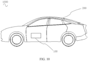
- an embodiment of the present disclosure provides a vehicle 1000.
- the vehicle 1000 includes a body 200 and an air spring system 100.
- the air spring system 100 is provided on the body 200.
- the sensor 91 detects a current state of the vehicle 1000, and transmits the current state of the vehicle 1000 to the controller 92 in real time.
- the controller 92 can send a command to the air spring system 100 after receiving the signal of the sensor 91 to actively and quickly adjust the air springs 10, thereby improving the safety and the operational stability of the vehicle 1000, enabling adaptive adjustment under non-hazardous conditions, reducing energy consumption and improving driving experience of the driver.
- An embodiment of the present disclosure provides a control method applicable to an air spring system.
- the air spring system may be the air spring system 100 described in any one of the above-mentioned embodiments.
- the control method provided by the embodiment of the present disclosure includes:
- step S10 the multi-way valve 30 is controlled to be in the first state.
- the first air port of the air spring 10 corresponding to the multi-way valve 30 can be connected to the air supply pipeline 21 through the multi-way valve 30, and the second air port of the air spring 10 can be connected to the atmosphere through the multi-way valve 30.
- step S20 when the multi-way valve 30 is in the first state, the pressure accumulators 20 are controlled to start working, and the air in the pressure accumulators 20 enters the air spring 10 through the air supply pipeline 21 and the first air port of the air spring 10, and therefore, the air spring 10 ascends under the air supply of the pressure accumulators 20.
- step S30 the multi-way valve 30 is controlled to be in the second state.
- the second air port of the air spring 10 corresponding to the multi-way valve 30 can be connected to the air supply pipeline 21 through the multi-way valve 30, and the first air port of the air spring 10 can be connected to the atmosphere through the multi-way valve 30.
- step S40 when the multi-way valve 30 is in the second state, the pressure accumulators 20 are controlled to start working, the air in the pressure accumulators 20 enters the air spring 10 through the air supply pipeline 21 and the second air port of the air spring 10, and therefore, the air spring 10 descends under the air supply of the pressure accumulators 20.
- the first air port of the air spring 10 corresponding to the multi-way valve 30 can be connected to the air supply pipeline 21, such that the air spring 10 ascends under the action of the pressure accumulators 20.
- the second air port of the air spring 10 can be connected to the air supply pipeline 21, and therefore, the air spring 10 descends under the action of the pressure accumulators 20.
- the object to which the first air port and the second air port of the air spring 10 are connected can be changed, so that the air in the pressure accumulators 20 passes through different air ports, resulting in different movements of the air spring 10.
- control method includes:
- the air springs 10 corresponding to the location of the target object will ascend rapidly, thereby reducing the risk of the driver, and through the cooperation of the pressure accumulators 20 and the air pump 50, the response speed can be increased to guarantee personal safety during emergency avoidance of obstacles.
- control method includes:
- the air springs 10 corresponding to the turning direction of the vehicle 1000 can descend under the air supply of the pressure accumulators 20, and the other air springs 10 can ascend rapidly under the air supply of the pressure accumulators 20 and the air pump 50, thereby reducing the tilt angle of the vehicle 1000, improving the stability of the vehicle 1000 when cornering with high speed, and reducing the risk of overturn.
- control method includes:
- the first air spring 11 is connected to the second air spring 12, and the third air spring 13 is connected to the fourth air spring 14.
- the front and rear suspensions can jointly absorb and consume vibration energy, thereby improving the stability and comfortableness of the vehicle 1000.
- control method includes:
- the first air spring 11 is connected to the third air spring 13 and the second air spring 12 is connected to the fourth air spring 14.
- the left and right suspensions can jointly absorb and consume vibration energy, thereby improving the stability and comfortableness of the vehicle 1000.
Landscapes
- Engineering & Computer Science (AREA)
- Mechanical Engineering (AREA)
- General Engineering & Computer Science (AREA)
- Physics & Mathematics (AREA)
- Acoustics & Sound (AREA)
- Aviation & Aerospace Engineering (AREA)
- Vehicle Body Suspensions (AREA)
Claims (15)
- Luftfedersystem (100) für ein Fahrzeug (1000), wobei das Luftfedersystem (100) Folgendes umfasst:eine Vielzahl von Luftfedern (10), wobei jede der Vielzahl von Luftfedern (10) dazu angeordnet ist, einer Federung des Fahrzeugs (1000) zu entsprechen, und einen ersten Luftanschluss (111) und einen zweiten Luftanschluss (122) aufweist;eine Luftzufuhrleitung (21);einen Druckspeicher (20), der auf der Luftzufuhrleitung (21) angeordnet ist und dazu konfiguriert ist, jeder der Vielzahl von Luftfedern (10) über den ersten Luftanschluss (111) und den zweiten Luftanschluss (122) der Luftfeder (10) Luftdruck zuzuführen; undeine Vielzahl von Mehrwegeventilen (30), die dazu konfiguriert sind, die Vielzahl von Luftfedern (10) mit der Luftzufuhrleitung (21) zu verbinden, und der Vielzahl von Luftfedern (10) in Eins-zu-Eins-Entsprechung entsprechen, wobei für jedes der Vielzahl von Mehrwegeventilen (30), wenn sich das Mehrwegeventil (30) in einem ersten Zustand befindet, der erste Luftanschluss (111) von einer dem Mehrwegeventil (30) entsprechenden der Vielzahl von Luftfedern (10) über das Mehrwegeventil mit der Luftzufuhrleitung (21) verbunden ist, der zweite Luftanschluss (122) der Luftfeder (10) über das Mehrwegeventil mit der Atmosphäre verbunden ist und die Luftfeder (10) unter Luftzufuhr des Druckspeichers (20) hochfährt; und wenn sich das Mehrwegeventil (30) in einem zweiten Zustand befindet, der erste Luftanschluss (111) der dem Mehrwegeventil (30) entsprechenden Luftfeder (10) über das Mehrwegeventil mit der Atmosphäre verbunden ist, der zweite Luftanschluss (122) der Luftfeder (10) über das Mehrwegeventil mit der Luftzufuhrleitung (21) verbunden ist und die Luftfeder unter Luftzufuhr des Druckspeichers (20) herunterfährt.
- Luftfedersystem (100) nach Anspruch 1, ferner umfassend eine Luftpumpe (50), die mit der Luftzufuhrleitung (21) verbunden ist, wobei die Luftpumpe (50) dazu konfiguriert ist, der Vielzahl von Luftfedern (10) über die Vielzahl von Mehrwegeventilen (30) Luft zuzuführen und Luft in den Druckspeicher (20) zu füllen.
- Fahrzeug (1000), umfassend: Luftfedersystem (100) nach Anspruch 1, wobei die Vielzahl von Luftfedern (10) eine zum Anordnen an einem linken Vorderrad des Fahrzeugs (1000) konfigurierte erste Luftfeder (11), eine zum Anordnen an einem linken Hinterrad des Fahrzeugs (1000) konfigurierte zweite Luftfeder (12), eine zum Anordnen an einem rechten Vorderrad des Fahrzeugs (1000) konfigurierte dritte Luftfeder (13) und eine zum Anordnen an einem rechten Hinterrad des Fahrzeugs (1000) konfigurierte vierte Luftfeder (14) umfasst; und
wobei die Vielzahl von Mehrwegeventilen (30) ein zum Verbinden der ersten Luftfeder (11) mit der Luftzufuhrleitung (21) konfiguriertes erstes Mehrwegeventil (31), ein zum Verbinden der zweiten Luftfeder (12) mit der Luftzufuhrleitung (21) konfiguriertes zweites Mehrwegeventil (32), ein zum Verbinden der dritten Luftfeder (13) mit der Luftzufuhrleitung (21) konfiguriertes drittes Mehrwegeventil (33) und ein zum Verbinden der vierten Luftfeder (14) mit der Luftzufuhrleitung (21) konfiguriertes viertes Mehrwegeventil (34) umfasst. - Fahrzeug (1000) nach Anspruch 3, ferner umfassend eine erste Verbindungsleitung (71), eine zweite Verbindungsleitung (72), eine dritte Verbindungsleitung (73), eine vierte Verbindungsleitung (74), ein auf der ersten Verbindungsleitung (71) angeordnetes erstes Durchgangsventil (81), ein auf der zweiten Verbindungsleitung (72) angeordnetes zweites Durchgangsventil (82), ein auf der dritten Verbindungsleitung (73) angeordnetes drittes Durchgangsventil (83) und ein auf der vierten Verbindungsleitung (74) angeordnetes viertes Durchgangsventil (84),
wobei ein Ende der ersten Verbindungsleitung (71) mit dem ersten Luftanschluss (111) der ersten Luftfeder (11) verbunden ist und das andere Ende der ersten Verbindungsleitung (71) mit dem zweiten Luftanschluss (122) der zweiten Luftfeder (12) verbunden ist; ein Ende der zweiten Verbindungsleitung (72) mit dem zweiten Luftanschluss (122) der zweiten Luftfeder (12) verbunden ist und das andere Ende der zweiten Verbindungsleitung (72) mit dem ersten Luftanschluss (111) der vierten Luftfeder (14) verbunden ist; ein Ende der dritten Verbindungsleitung (73) mit dem ersten Luftanschluss (111) der dritten Luftfeder (13) verbunden ist und das andere Ende der dritten Verbindungsleitung (73) mit dem zweiten Luftanschluss (122) der vierten Luftfeder (14) verbunden ist; und ein Ende der vierten Verbindungsleitung (74) mit dem ersten Luftanschluss (111) der dritten Luftfeder (13) verbunden ist und das andere Ende der vierten Verbindungsleitung (74) mit dem zweiten Luftanschluss (122) der ersten Luftfeder (11) verbunden ist. - Fahrzeug (1000) nach Anspruch 4, wobei, wenn sich eine Frontseite, eine linke Seite oder eine rechte Seite des Fahrzeugs (1000) einem Zielobjekt nähert, unter dem ersten Mehrwegeventil (31), dem zweiten Mehrwegeventil (32), dem dritten Mehrwegeventil (33) und dem vierten Mehrwegeventil (34), sich zwei Mehrwegeventile (30) nah bei dem Zielobjekt in dem ersten Zustand befinden, sich die anderen zwei Mehrwegeventile (30) in einem dritten Zustand befinden; sich das erste Durchgangsventil (81), das zweite Durchgangventil (82), das dritte Durchgangsventil (83) und das vierte Durchgangsventil (84) alle in einem Absperrzustand befinden; unter der ersten Luftfeder (11), der zweiten Luftfeder (12), der dritten Luftfeder (13) und der vierten Luftfeder (14) die ersten Luftanschlüsse (111) und die zweiten Luftanschlüsse (122) von zwei den anderen zwei Mehrwegeventilen (30) in dem dritten Zustand entsprechenden Luftfedern (10) von dem Druckspeicher (20) getrennt sind und die Zustände der zwei Luftfedern (10) unverändert bleiben und die anderen zwei Luftfedern (10) in der Lage sind, unter der Luftzufuhr des Druckspeichers (20) hochzufahren.
- Fahrzeug (1000) nach Anspruch 4, wobei, wenn ein Kurvenfahrtwinkel des Fahrzeugs (1000) größer als ein voreingestellter Winkel ist und eine Fahrzeuggeschwindigkeit des Fahrzeugs (1000) größer als eine voreingestellte Geschwindigkeit ist, unter dem ersten Mehrwegeventil (31), dem zweiten Mehrwegeventil (32), dem dritten Mehrwegeventil (33) und dem vierten Mehrwegeventil (34) sich zwei einer Richtung der Kurvenfahrt des Fahrzeugs (1000) entsprechende Mehrwegeventile (30) in einem zweiten Zustand befinden, sich die anderen zwei Mehrwegeventile (30) in dem ersten Zustand befinden; sich das erste Durchgangsventil (81) und das dritte Durchgangsventil (83) in einem Absperrzustand befinden und sich das zweite Durchgangsventil (82) und das vierte Durchgangsventil (84) in einem verbundenen Zustand befinden; unter der ersten Luftfeder (11), der zweiten Luftfeder (12), der dritten Luftfeder (13) und der vierten Luftfeder (14) zwei den zwei Mehrwegeventilen (30) in dem zweiten Zustand entsprechende Luftfedern (10) mit den ersten Luftanschlüssen (111) und den zweiten Luftanschlüssen (122) derselben von dem Druckspeicher (20) getrennt sind und in der Lage sind, unter der Luftzufuhr des Druckspeichers (20) herunterzufahren, und die anderen zwei Luftfedern (10) in der Lage sind, unter Luftzufuhr des Druckspeichers (20) hochzufahren.
- Fahrzeug (1000) nach Anspruch 4, wobei, wenn sich das Fahrzeug (1000) in einem holpernden Zustand befindet, sich jedes der Vielzahl von Mehrwegeventilen (30) in einem dritten Zustand befindet; sich das zweite Durchgangsventil (82) und das vierte Durchgangsventil (84) in einem Absperrzustand befinden, sich das erste Durchgangsventil (81) und das dritte Durchgangsventil (83) in einem verbundenen Zustand befinden; der erste Luftanschluss (111) der ersten Luftfeder (11) über die erste Verbindungsleitung (71) mit dem zweiten Luftanschluss (122) der zweiten Luftfeder (12) verbunden ist und der erste Luftanschluss (111) der dritten Luftfeder (13) über die dritte Verbindungsleitung (73) mit dem zweiten Luftanschluss (122) der vierten Luftfeder (14) verbunden ist.
- Fahrzeug (1000) nach Anspruch 4, wobei, wenn eine Anzahl von Kurvenfahrten des Fahrzeugs (1000) innerhalb eines vorgegebenen Zeitraums größer als eine voreingestellte Anzahl ist, sich jedes der Mehrwegeventile (30) in einem dritten Zustand befindet; sich das erste Durchgangsventil (81) und das dritte Durchgangsventil (83) in einem Absperrzustand befinden und sich das zweite Durchgangsventil (82) und das vierte Durchgangsventil (84) in einem verbundenen Zustand befinden; der zweite Luftanschluss (122) der ersten Luftfeder (11) über die vierte Verbindungsleitung (74) mit dem zweiten Luftanschluss (122) der dritten Luftfeder (13) verbunden ist und der zweite Luftanschluss (122) der zweiten Luftfeder (12) über die zweite Verbindungsleitung (72) mit dem ersten Luftanschluss (111) der vierten Luftfeder (14) verbunden ist.
- Fahrzeug (1000) nach Anspruch 4, wobei, wenn sich eine Heckseite des Fahrzeugs (1000) einem Zielobjekt nähert, unter dem ersten Mehrwegeventil (31), dem zweiten Mehrwegeventil (32), dem dritten Mehrwegeventil (33) und dem vierten Mehrwegeventil (34) sich zwei Mehrwegeventile (30) nah bei dem Zielobjekt in einem zweiten Zustand befinden, sich die anderen zwei Mehrwegeventile (30) in einem dritten Zustand befinden; sich das erste Durchgangsventil (81), das zweite Durchgangventil (82), das dritte Durchgangsventil (83) und das vierte Durchgangsventil (84) alle in einem Absperrzustand befinden; unter der ersten Luftfeder (11), der zweiten Luftfeder (12), der dritten Luftfeder (13) und der vierten Luftfeder (14) zwei den zwei Mehrwegeventilen (30) in dem zweiten Zustand entsprechende Luftfedern mit den ersten Luftanschlüssen (111) und den zweiten Luftanschlüssen (122) derselben von dem Druckspeicher (20) getrennt sind und in der Lage sind, unter der Luftzufuhr des Druckspeichers (20) herunterzufahren, und die Zustände der anderen zwei Luftfedern (10) unverändert bleiben.
- Fahrzeug (1000) nach einem der Ansprüche 3 bis 9, ferner umfassend:
eine Karosserie, wobei das Luftfedersystem (100) an der Karosserie angeordnet ist. - Steuerverfahren für ein Fahrzeug (1000) mit einem Luftfedersystem (100), wobei das Luftfedersystem (100) Folgendes umfasst:eine Vielzahl von Luftfedern (10), wobei jede der Vielzahl von Luftfedern (10) dazu angeordnet ist, einer Federung des Fahrzeugs (1000) zu entsprechen, und einen ersten Luftanschluss (111) und einen zweiten Luftanschluss (122) aufweist;einen Druckspeicher (20), der auf einer Luftzufuhrleitung (21) angeordnet ist und dazu konfiguriert ist, jeder der Vielzahl von Luftfedern (10) über den ersten Luftanschluss (111) und den zweiten Luftanschluss (122) der Luftfeder (10) Luftdruck zuzuführen; undeine Vielzahl von Mehrwegeventilen (30), die dazu konfiguriert sind, die Vielzahl von Luftfedern (10) mit der Luftzufuhrleitung (21) zu verbinden, und der Vielzahl von Luftfedern (10) in Eins-zu-Eins-Entsprechung entsprechen, undwobei das Steuerverfahren Folgendes umfasst:(S10) Steuern eines der Vielzahl von Mehrwegeventilen (30) dazu, sich in einem ersten Zustand zu befinden, um den ersten Luftanschluss (111) einer dem Mehrwegeventil (30) entsprechenden der Vielzahl von Luftfedern (30) über das Mehrwegeventil mit der Luftzufuhrleitung (21) zu verbinden und den zweiten Luftanschluss (122) der Luftfeder (10) über das Mehrwegeventil mit der Atmosphäre zu verbinden;(S20) Steuern des Druckspeichers (20) dazu, zu arbeiten, um es der dem Mehrwegeventil (30) entsprechenden Luftfeder (10) zu ermöglichen, unter Luftzufuhr des Druckspeichers (20) hochzufahren, wenn sich das Mehrwegeventil (30) in dem ersten Zustand befindet,(S30) Steuern eines der Vielzahl von Mehrwegeventilen (30) dazu, sich in einem zweiten Zustand zu befinden, um den ersten Luftanschluss (111) einer dem Mehrwegeventil (30) entsprechenden der Vielzahl von Luftfedern (10) über das Mehrwegeventil mit der Atmosphäre zu verbinden und den zweiten Luftanschluss (122) der Luftfeder (10) über das Mehrwegeventil mit der Luftzufuhrleitung (21) zu verbinden; und(S40) Steuern des Druckspeichers (20) dazu, zu arbeiten, um es der dem Mehrwegeventil (30) entsprechenden Luftfeder (10) zu ermöglichen, unter der Luftzufuhr des Druckspeichers (20) herunterzufahren, wenn sich das Mehrwegeventil (30) in dem zweiten Zustand befindet.
- Steuerverfahren nach Anspruch 11, wobei die Vielzahl von Luftfedern (10) eine zum Anordnen an einem linken Vorderrad des Fahrzeugs (1000) konfigurierte erste Luftfeder (11), eine zum Anordnen an einem linken Hinterrad des Fahrzeugs (1000) konfigurierte zweite Luftfeder (12), eine zum Anordnen an einem rechten Vorderrad des Fahrzeugs (1000) konfigurierte dritte Luftfeder (13) und eine zum Anordnen an einem rechten Hinterrad des Fahrzeugs (1000) konfigurierte vierte Luftfeder (14) umfasst;wobei die Vielzahl von Mehrwegeventilen (30) ein zum Verbinden der ersten Luftfeder (11) mit der Luftzufuhrleitung (21) konfiguriertes erstes Mehrwegeventil (31), ein zum Verbinden der zweiten Luftfeder (12) mit der Luftzufuhrleitung (21) konfiguriertes zweites Mehrwegeventil (32), ein zum Verbinden der dritten Luftfeder (13) mit der Luftzufuhrleitung (21) konfiguriertes drittes Mehrwegeventil (33) und ein zum Verbinden der vierten Luftfeder (14) mit der Luftzufuhrleitung (21) konfiguriertes viertes Mehrwegeventil (34) umfasst;wobei das Luftfedersystem (100) ferner eine erste Verbindungsleitung (71), eine zweite Verbindungsleitung (72), eine dritte Verbindungsleitung (73), eine vierte Verbindungsleitung (74), ein auf der ersten Verbindungsleitung (71) angeordnetes erstes Durchgangsventil (81), ein auf der zweiten Verbindungsleitung (72) angeordnetes zweites Durchgangsventil (82), ein auf der dritten Verbindungsleitung (73) angeordnetes drittes Durchgangsventil (83) und ein auf der vierten Verbindungsleitung (74) angeordnetes viertes Durchgangsventil (84) umfasst;wobei ein Ende der ersten Verbindungsleitung (71) mit dem ersten Luftanschluss (111) der ersten Luftfeder (11) verbunden ist und das andere Ende der ersten Verbindungsleitung (71) mit dem zweiten Luftanschluss (122) der zweiten Luftfeder (12) verbunden ist; ein Ende der zweiten Verbindungsleitung (72) mit dem zweiten Luftanschluss (122) der zweiten Luftfeder (12) verbunden ist und das andere Ende der zweiten Verbindungsleitung (72) mit dem ersten Luftanschluss (111) der vierten Luftfeder (14) verbunden ist; ein Ende der dritten Verbindungsleitung (73) mit dem ersten Luftanschluss (111) der dritten Luftfeder (13) verbunden ist und das andere Ende der dritten Verbindungsleitung (73) mit dem zweiten Luftanschluss (122) der vierten Luftfeder (14) verbunden ist; und ein Ende der vierten Verbindungsleitung (74) mit dem ersten Luftanschluss (111) der dritten Luftfeder (13) verbunden ist und das andere Ende der vierten Verbindungsleitung (74) mit dem zweiten Luftanschluss (122) der ersten Luftfeder (11) verbunden ist;wobei das Steuerverfahren Folgendes umfasst:(S50) wenn sich eine Frontseite, eine linke Seite oder eine rechte Seite des Fahrzeugs (1000) einem Zielobjekt nähert, Steuern, unter dem ersten Mehrwegegentil (31), dem zweiten Mehrwegeventil (32), dem dritten Mehrwegeventil (33) und dem vierten Mehrwegeventil (34), von zwei Mehrwegeventilen (30) nah bei dem Zielobjekt dazu, sich in dem ersten Zustand zu befinden, und Steuern der anderen zwei Mehrwegeventile (30) dazu, sich in einem dritten Zustand zu befinden, wobei unter der ersten Luftfeder (11), der zweiten Luftfeder (12), der dritten Luftfeder (13) und der vierten Luftfeder (14) die ersten Luftanschlüsse (111) und die zweiten Luftanschlüsse (122) von zwei den anderen zwei Mehrwegeventilen (30) in dem dritten Zustand entsprechenden Luftfedern von dem Druckspeicher (20) getrennt sind;(S60) Steuern des ersten Durchgangsventils (81), des zweiten Durchgangsventils (82), des dritten Durchgangsventils (83) und des vierten Durchgangsventils (84) dazu, sich in einem Absperrzustand zu befinden; und(S70) Steuern des Druckspeichers (20) dazu, zu arbeiten, um es den anderen zwei Luftfedern (10) nah bei dem Zielobjekt zu ermöglichen, unter der Luftzufuhr des Druckspeichers (20) hochzufahren und zu ermöglichen, dass Zustände der den anderen zwei Mehrwegeventilen (30) in dem dritten Zustand entsprechenden zwei Luftfedern (10) unverändert bleiben.
- Steuerverfahren nach Anspruch 11, wobei die Vielzahl von Luftfedern (10) eine zum Anordnen an einem linken Vorderrad des Fahrzeugs (1000) konfigurierte erste Luftfeder (11), eine zum Anordnen an einem linken Hinterrad des Fahrzeugs (1000) konfigurierte zweite Luftfeder (12), eine zum Anordnen an einem rechten Vorderrad des Fahrzeugs (1000) konfigurierte dritte Luftfeder (13) und eine zum Anordnen an einem rechten Hinterrad des Fahrzeugs (1000) konfigurierte vierte Luftfeder (14) umfasst; undwobei die Vielzahl von Mehrwegeventilen (30) ein zum Verbinden der ersten Luftfeder (11) mit der Luftzufuhrleitung (21) konfiguriertes erstes Mehrwegeventil (31), ein zum Verbinden der zweiten Luftfeder (12) mit der Luftzufuhrleitung (21) konfiguriertes zweites Mehrwegeventil (32), ein zum Verbinden der dritten Luftfeder (13) mit der Luftzufuhrleitung (21) konfiguriertes drittes Mehrwegeventil (33) und ein zum Verbinden der vierten Luftfeder (14) mit der Luftzufuhrleitung (21) konfiguriertes viertes Mehrwegeventil (34) umfasst;wobei das Luftfedersystem (100) ferner eine erste Verbindungsleitung (71), eine zweite Verbindungsleitung (72), eine dritte Verbindungsleitung (73), eine vierte Verbindungsleitung (74), ein auf der ersten Verbindungsleitung (71) angeordnetes erstes Durchgangsventil (81), ein auf der zweiten Verbindungsleitung (72) angeordnetes zweites Durchgangsventil (82), ein auf der dritten Verbindungsleitung (73) angeordnetes drittes Durchgangsventil (83) und ein auf der vierten Verbindungsleitung (74) angeordnetes viertes Durchgangsventil (84) umfasst;wobei ein Ende der ersten Verbindungsleitung (71) mit dem ersten Luftanschluss (111) der ersten Luftfeder (11) verbunden ist und das andere Ende der ersten Verbindungsleitung (71) mit dem zweiten Luftanschluss (122) der zweiten Luftfeder (12) verbunden ist; ein Ende der zweiten Verbindungsleitung (72) mit dem zweiten Luftanschluss (122) der zweiten Luftfeder (12) verbunden ist und das andere Ende der zweiten Verbindungsleitung (72) mit dem ersten Luftanschluss (111) der vierten Luftfeder (14) verbunden ist; ein Ende der dritten Verbindungsleitung (73) mit dem ersten Luftanschluss (111) der dritten Luftfeder (13) verbunden ist und das andere Ende der dritten Verbindungsleitung (73) mit dem zweiten Luftanschluss (122) der vierten Luftfeder (14) verbunden ist; und ein Ende der vierten Verbindungsleitung (74) mit dem ersten Luftanschluss (111) der dritten Luftfeder (13) verbunden ist und das andere Ende der vierten Verbindungsleitung (74) mit dem zweiten Luftanschluss (122) der ersten Luftfeder (11) verbunden ist;wobei das Steuerverfahren Folgendes umfasst:(S80) wenn ein Kurvenfahrtwinkel des Fahrzeugs (1000) größer als ein voreingestellter Winkel ist und eine Fahrzeuggeschwindigkeit des Fahrzeugs (1000) größer als eine voreingestellte Geschwindigkeit ist, Steuern, unter dem erstem Mehrwegeventil (31), dem zweiten Mehrwegeventil (32), dem dritten Mehrwegeventil (33) und dem vierten Mehrwegeventil (34), von zwei einer Richtung der Kurvenfahrt des Fahrzeugs (1000) entsprechenden Mehrwegeventilen (30) dazu, sich in einem zweiten Zustand zu befinden, und Steuern der anderen zwei Mehrwegeventile (30) dazu sich in dem ersten Zustand zu befinden, wobei die ersten Luftanschlüsse (111) und die zweiten Luftanschlüsse (122) von zwei den zwei Mehrwegeventilen (30) in dem zweiten Zustand entsprechenden Luftfedern (10) von dem Druckspeicher (20) getrennt sind;(S90) Steuern des ersten Durchgangsventils (81) und des dritten Durchgangsventils (83) dazu, sich in einem Absperrzustand zu befinden, und Steuern des zweiten Durchgangsventils (82) und des vierten Durchgangsventils (84) dazu, sich in einem verbundenen Zustand zu befinden; und(S100) Steuern des Druckspeichers (20) dazu, zu arbeiten, um den zwei den zwei Mehrwegeventilen (30) in dem zweiten Zustand entsprechenden Luftfedern (10) zu ermöglichen, unter Luftzufuhr des Druckspeichers (20) herunterzufahren, und den anderen zwei Luftfedern (10) zu ermöglichen, unter Luftzufuhr des Druckspeichers (20) hochzufahren.
- Steuerverfahren nach Anspruch 11, wobei die Vielzahl von Luftfedern (10) eine zum Anordnen an einem linken Vorderrad des Fahrzeugs (1000) konfigurierte erste Luftfeder (11), eine zum Anordnen an einem linken Hinterrad des Fahrzeugs (1000) konfigurierte zweite Luftfeder (12), eine zum Anordnen an einem rechten Vorderrad des Fahrzeugs (1000) konfigurierte dritte Luftfeder (13) und eine zum Anordnen an einem rechten Hinterrad des Fahrzeugs (1000) konfigurierte vierte Luftfeder (14) umfasst;wobei die Vielzahl von Mehrwegeventilen (30) ein zum Verbinden der ersten Luftfeder (11) mit der Luftzufuhrleitung (21) konfiguriertes erstes Mehrwegeventil (31), ein zum Verbinden der zweiten Luftfeder (12) mit der Luftzufuhrleitung (21) konfiguriertes zweites Mehrwegeventil (32), ein zum Verbinden der dritten Luftfeder (13) mit der Luftzufuhrleitung (21) konfiguriertes drittes Mehrwegeventil (33) und ein zum Verbinden der vierten Luftfeder (14) mit der Luftzufuhrleitung (21) konfiguriertes viertes Mehrwegeventil (34) umfasst;wobei das Luftfedersystem (100) ferner eine erste Verbindungsleitung (71), eine zweite Verbindungsleitung (72), eine dritte Verbindungsleitung (73), eine vierte Verbindungsleitung (74), ein auf der ersten Verbindungsleitung (71) angeordnetes erstes Durchgangsventil (81), ein auf der zweiten Verbindungsleitung (72) angeordnetes zweites Durchgangsventil (82), ein auf der dritten Verbindungsleitung (73) angeordnetes drittes Durchgangsventil (83) und ein auf der vierten Verbindungsleitung (74) angeordnetes viertes Durchgangsventil (84) umfasst;wobei ein Ende der ersten Verbindungsleitung (71) mit dem ersten Luftanschluss (111) der ersten Luftfeder (11) verbunden ist und das andere Ende der ersten Verbindungsleitung (71) mit dem zweiten Luftanschluss (122) der zweiten Luftfeder (12) verbunden ist; ein Ende der zweiten Verbindungsleitung (72) mit dem zweiten Luftanschluss (122) der zweiten Luftfeder (12) verbunden ist und das andere Ende der zweiten Verbindungsleitung (72) mit dem ersten Luftanschluss (111) der vierten Luftfeder (14) verbunden ist; ein Ende der dritten Verbindungsleitung (73) mit dem ersten Luftanschluss (111) der dritten Luftfeder (13) verbunden ist und das andere Ende der dritten Verbindungsleitung (73) mit dem zweiten Luftanschluss (122) der vierten Luftfeder (14) verbunden ist; und ein Ende der vierten Verbindungsleitung (74) mit dem ersten Luftanschluss (111) der dritten Luftfeder (13) verbunden ist und das andere Ende der vierten Verbindungsleitung (74) mit dem zweiten Luftanschluss (122) der ersten Luftfeder (11) verbunden ist;wobei das Steuerverfahren Folgendes umfasst:(S110) wenn sich das Fahrzeug (1000) in einem holpernden Zustand befindet, Steuern jedes der Vielzahl von Mehrwegeventilen (30) dazu, sich in einem dritten Zustand zu befinden; und(S120) Steuern des zweiten Durchgangsventils (82) und des vierten Durchgangsventils (84) dazu, sich in einem Absperrzustand befinden, und Steuern des ersten Durchgangsventils (81) und des dritten Durchgangsventils (83) dazu, sich in einem verbundenen Zustand zu befinden; wobei der erste Luftanschluss (111) der ersten Luftfeder (11) über die erste Verbindungsleitung (71) mit dem zweiten Luftanschluss (122) der zweiten Luftfeder (12) verbunden ist und der erste Luftanschluss (111) der dritten Luftfeder (13) über die dritte Verbindungsleitung (73) mit dem zweiten Luftanschluss (122) der vierten Luftfeder (14) verbunden ist.
- Steuerverfahren nach Anspruch 11, wobei die Vielzahl von Luftfedern (10) eine zum Anordnen an einem linken Vorderrad des Fahrzeugs (1000) konfigurierte erste Luftfeder (11), eine zum Anordnen an einem linken Hinterrad des Fahrzeugs (1000) konfigurierte zweite Luftfeder (12), eine zum Anordnen an einem rechten Vorderrad des Fahrzeugs (1000) konfigurierte dritte Luftfeder (13) und eine zum Anordnen an einem rechten Hinterrad des Fahrzeugs (1000) konfigurierte vierte Luftfeder (14) umfasst; undwobei die Vielzahl von Mehrwegeventilen (30) ein zum Verbinden der ersten Luftfeder (11) mit der Luftzufuhrleitung (21) konfiguriertes erstes Mehrwegeventil (31), ein zum Verbinden der zweiten Luftfeder (12) mit der Luftzufuhrleitung (21) konfiguriertes zweites Mehrwegeventil (32), ein zum Verbinden der dritten Luftfeder (13) mit der Luftzufuhrleitung (21) konfiguriertes drittes Mehrwegeventil (33) und ein zum Verbinden der vierten Luftfeder (14) mit der Luftzufuhrleitung (21) konfiguriertes viertes Mehrwegeventil (34) umfasst;wobei das Luftfedersystem (100) ferner eine erste Verbindungsleitung (71), eine zweite Verbindungsleitung (72), eine dritte Verbindungsleitung (73), eine vierte Verbindungsleitung (74), ein auf der ersten Verbindungsleitung (71) angeordnetes erstes Durchgangsventil (81), ein auf der zweiten Verbindungsleitung (72) angeordnetes zweites Durchgangsventil (82), ein auf der dritten Verbindungsleitung (73) angeordnetes drittes Durchgangsventil (83) und ein auf der vierten Verbindungsleitung (74) angeordnetes viertes Durchgangsventil (84) umfasst;wobei ein Ende der ersten Verbindungsleitung (71) mit dem ersten Luftanschluss (111) der ersten Luftfeder (11) verbunden ist und das andere Ende der ersten Verbindungsleitung (71) mit dem zweiten Luftanschluss (122) der zweiten Luftfeder (12) verbunden ist; ein Ende der zweiten Verbindungsleitung (72) mit dem zweiten Luftanschluss (122) der zweiten Luftfeder (12) verbunden ist und das andere Ende der zweiten Verbindungsleitung (72) mit dem ersten Luftanschluss (111) der vierten Luftfeder (14) verbunden ist; ein Ende der dritten Verbindungsleitung (73) mit dem ersten Luftanschluss (111) der dritten Luftfeder (13) verbunden ist und das andere Ende der dritten Verbindungsleitung (73) mit dem zweiten Luftanschluss (122) der vierten Luftfeder (14) verbunden ist; und ein Ende der vierten Verbindungsleitung (74) mit dem ersten Luftanschluss (111) der dritten Luftfeder (13) verbunden ist und das andere Ende der vierten Verbindungsleitung (74) mit dem zweiten Luftanschluss (122) der ersten Luftfeder (11) verbunden ist;wobei das Steuerverfahren Folgendes umfasst:(S130) wenn eine Anzahl von Kurvenfahrten des Fahrzeugs (1000) innerhalb eines vorgegebenen Zeitraums größer als eine voreingestellte Anzahl ist, Steuern aller der Vielzahl von Mehrwegeventilen (30) dazu, sich in einem dritten Zustand zu befinden; und(S140) Steuern des ersten Durchgangsventils (81) und des dritten Durchgangsventils (83) dazu, sich in einem Absperrzustand zu befinden, und Steuern des zweiten Durchgangsventils (82) und des vierten Durchgangsventils (84) dazu, sich in einem verbundenen Zustand zu befinden, wobei der zweite Luftanschluss (122) der ersten Luftfeder (11) über die vierte Verbindungsleitung (74) mit dem zweiten Luftanschluss (122) der dritten Luftfeder (13) verbunden ist und der zweite Luftanschluss (122) der zweiten Luftfeder (12) über die zweite Verbindungsleitung (72) mit dem ersten Luftanschluss (111) der vierten Luftfeder (14) verbunden ist.
Applications Claiming Priority (1)
| Application Number | Priority Date | Filing Date | Title |
|---|---|---|---|
| CN202110087566.2A CN112879487B (zh) | 2021-01-22 | 2021-01-22 | 空气弹簧系统、车辆和控制方法 |
Publications (3)
| Publication Number | Publication Date |
|---|---|
| EP4032732A1 EP4032732A1 (de) | 2022-07-27 |
| EP4032732C0 EP4032732C0 (de) | 2023-10-11 |
| EP4032732B1 true EP4032732B1 (de) | 2023-10-11 |
Family
ID=76050178
Family Applications (1)
| Application Number | Title | Priority Date | Filing Date |
|---|---|---|---|
| EP21213324.3A Active EP4032732B1 (de) | 2021-01-22 | 2021-12-09 | Luftfedersystem, fahrzeug und steuerungsverfahren |
Country Status (2)
| Country | Link |
|---|---|
| EP (1) | EP4032732B1 (de) |
| CN (1) | CN112879487B (de) |
Families Citing this family (4)
| Publication number | Priority date | Publication date | Assignee | Title |
|---|---|---|---|---|
| US12251978B2 (en) | 2023-05-15 | 2025-03-18 | DRiV Automotive Inc. | Single axle roll control system that includes a dual chamber ball-screw mechanism |
| US12344065B2 (en) | 2023-05-15 | 2025-07-01 | Advanced Suspension Technology Llc | Single axle roll control system with multiple pressurizing devices arranged in series |
| US12083851B1 (en) * | 2023-05-15 | 2024-09-10 | DRiV Automotive Inc. | Single axle roll control system with multiple circuit-specific pressurizing devices |
| US12083848B1 (en) | 2023-05-15 | 2024-09-10 | DRiV Automotive Inc. | Single axle roll control system with dual impeller pump arrangement |
Family Cites Families (8)
| Publication number | Priority date | Publication date | Assignee | Title |
|---|---|---|---|---|
| US3356954A (en) * | 1964-12-09 | 1967-12-05 | Schmidt Karl Heinz | Wheel suspension system for road vehicles and cross-country vehicles |
| JP4875641B2 (ja) * | 2008-02-25 | 2012-02-15 | 株式会社クボタ | 作業車のサスペンション構造 |
| CN101417596B (zh) * | 2008-11-18 | 2011-01-19 | 江苏大学 | 一种汽车空气悬架的控制方法 |
| CN102059929B (zh) * | 2010-12-20 | 2012-07-18 | 三一汽车起重机械有限公司 | 油气悬挂系统及具有该系统的轮式车辆 |
| CA2956933A1 (en) * | 2017-02-03 | 2018-08-03 | Kelso Technologies Inc. | Active suspension control system and method for no-road vehicles |
| CN108297642A (zh) * | 2018-02-06 | 2018-07-20 | 海南大学 | 共享气室空气悬架系统及其控制方法 |
| JP2020044979A (ja) * | 2018-09-19 | 2020-03-26 | 日立オートモティブシステムズ株式会社 | エアサスペンション装置 |
| CN109159636B (zh) * | 2018-10-30 | 2023-10-20 | 吉林大学 | 一种特种车辆用液压式可调高度悬架及其控制方法 |
-
2021
- 2021-01-22 CN CN202110087566.2A patent/CN112879487B/zh active Active
- 2021-12-09 EP EP21213324.3A patent/EP4032732B1/de active Active
Also Published As
| Publication number | Publication date |
|---|---|
| CN112879487B (zh) | 2022-10-14 |
| CN112879487A (zh) | 2021-06-01 |
| EP4032732C0 (de) | 2023-10-11 |
| EP4032732A1 (de) | 2022-07-27 |
Similar Documents
| Publication | Publication Date | Title |
|---|---|---|
| EP4032732B1 (de) | Luftfedersystem, fahrzeug und steuerungsverfahren | |
| US8075002B1 (en) | Semi-active suspension system | |
| US5066041A (en) | Control system for stabilizing the rolling of a vehicle | |
| US7637511B2 (en) | Method and system for electronic shock absorbing by adjusting the retractile status of a retractable absorber | |
| US9636965B2 (en) | Suspension system | |
| CN204037280U (zh) | 车辆悬架系统和机动车 | |
| US6264213B1 (en) | Suspension system for land vehicles, in particular motor vehicles | |
| KR102172510B1 (ko) | 에어 서스펜션이 장착된 자동차의 높이를 제어하기 위한 방법 | |
| US20170050697A1 (en) | Variable ride height systems and methods | |
| KR102733403B1 (ko) | 차량 운동 제어 장치 | |
| US20020190486A1 (en) | Torsion bar actuator for suspension trim height and roll control | |
| JP2010208619A (ja) | 車両挙動制御装置 | |
| Strassberger et al. | BMW's dynamic drive: an active stabilizer bar system | |
| KR102725579B1 (ko) | 차량 및 그 제어 방법 | |
| US20240262150A1 (en) | Suspension system and control method thereof, and vehicle | |
| CN104097482A (zh) | 汽车ecas控制方法和装置 | |
| EP2017101B1 (de) | Fahrzeugrollensteuersystem | |
| CN119058654A (zh) | 底盘域控制总成及车辆 | |
| JP5250349B2 (ja) | 制動力制御装置 | |
| CN206344652U (zh) | 一种可实现主动与半主动切换控制的油气悬架系统 | |
| CN111824048B (zh) | 车辆爆胎的控制方法、装置和车辆 | |
| US20070241522A1 (en) | Active automobile turn gravity change control apparatus | |
| CN203157644U (zh) | 汽车ecas控制装置 | |
| CN119058655A (zh) | 底盘域控制总成及车辆 | |
| KR102416935B1 (ko) | 차량용 능동형 현가장치 |
Legal Events
| Date | Code | Title | Description |
|---|---|---|---|
| PUAI | Public reference made under article 153(3) epc to a published international application that has entered the european phase |
Free format text: ORIGINAL CODE: 0009012 |
|
| STAA | Information on the status of an ep patent application or granted ep patent |
Free format text: STATUS: THE APPLICATION HAS BEEN PUBLISHED |
|
| AK | Designated contracting states |
Kind code of ref document: A1 Designated state(s): AL AT BE BG CH CY CZ DE DK EE ES FI FR GB GR HR HU IE IS IT LI LT LU LV MC MK MT NL NO PL PT RO RS SE SI SK SM TR |
|
| STAA | Information on the status of an ep patent application or granted ep patent |
Free format text: STATUS: REQUEST FOR EXAMINATION WAS MADE |
|
| 17P | Request for examination filed |
Effective date: 20230123 |
|
| RBV | Designated contracting states (corrected) |
Designated state(s): AL AT BE BG CH CY CZ DE DK EE ES FI FR GB GR HR HU IE IS IT LI LT LU LV MC MK MT NL NO PL PT RO RS SE SI SK SM TR |
|
| GRAP | Despatch of communication of intention to grant a patent |
Free format text: ORIGINAL CODE: EPIDOSNIGR1 |
|
| STAA | Information on the status of an ep patent application or granted ep patent |
Free format text: STATUS: GRANT OF PATENT IS INTENDED |
|
| RIC1 | Information provided on ipc code assigned before grant |
Ipc: B60G 17/052 20060101ALI20230317BHEP Ipc: B60G 21/073 20060101ALI20230317BHEP Ipc: B60G 21/067 20060101ALI20230317BHEP Ipc: B60G 17/015 20060101ALI20230317BHEP Ipc: B60G 17/0165 20060101ALI20230317BHEP Ipc: B60G 17/016 20060101ALI20230317BHEP Ipc: B60G 11/27 20060101AFI20230317BHEP |
|
| INTG | Intention to grant announced |
Effective date: 20230414 |
|
| GRAS | Grant fee paid |
Free format text: ORIGINAL CODE: EPIDOSNIGR3 |
|
| GRAA | (expected) grant |
Free format text: ORIGINAL CODE: 0009210 |
|
| STAA | Information on the status of an ep patent application or granted ep patent |
Free format text: STATUS: THE PATENT HAS BEEN GRANTED |
|
| AK | Designated contracting states |
Kind code of ref document: B1 Designated state(s): AL AT BE BG CH CY CZ DE DK EE ES FI FR GB GR HR HU IE IS IT LI LT LU LV MC MK MT NL NO PL PT RO RS SE SI SK SM TR |
|
| REG | Reference to a national code |
Ref country code: GB Ref legal event code: FG4D |
|
| REG | Reference to a national code |
Ref country code: CH Ref legal event code: EP |
|
| REG | Reference to a national code |
Ref country code: DE Ref legal event code: R096 Ref document number: 602021005807 Country of ref document: DE |
|
| REG | Reference to a national code |
Ref country code: IE Ref legal event code: FG4D |
|
| U01 | Request for unitary effect filed |
Effective date: 20231107 |
|
| U07 | Unitary effect registered |
Designated state(s): AT BE BG DE DK EE FI FR IT LT LU LV MT NL PT SE SI Effective date: 20231110 |
|
| U20 | Renewal fee for the european patent with unitary effect paid |
Year of fee payment: 3 Effective date: 20231227 |
|
| PG25 | Lapsed in a contracting state [announced via postgrant information from national office to epo] |
Ref country code: GR Free format text: LAPSE BECAUSE OF FAILURE TO SUBMIT A TRANSLATION OF THE DESCRIPTION OR TO PAY THE FEE WITHIN THE PRESCRIBED TIME-LIMIT Effective date: 20240112 |
|
| PG25 | Lapsed in a contracting state [announced via postgrant information from national office to epo] |
Ref country code: IS Free format text: LAPSE BECAUSE OF FAILURE TO SUBMIT A TRANSLATION OF THE DESCRIPTION OR TO PAY THE FEE WITHIN THE PRESCRIBED TIME-LIMIT Effective date: 20240211 |
|
| PG25 | Lapsed in a contracting state [announced via postgrant information from national office to epo] |
Ref country code: ES Free format text: LAPSE BECAUSE OF FAILURE TO SUBMIT A TRANSLATION OF THE DESCRIPTION OR TO PAY THE FEE WITHIN THE PRESCRIBED TIME-LIMIT Effective date: 20231011 |
|
| PG25 | Lapsed in a contracting state [announced via postgrant information from national office to epo] |
Ref country code: IS Free format text: LAPSE BECAUSE OF FAILURE TO SUBMIT A TRANSLATION OF THE DESCRIPTION OR TO PAY THE FEE WITHIN THE PRESCRIBED TIME-LIMIT Effective date: 20240211 Ref country code: GR Free format text: LAPSE BECAUSE OF FAILURE TO SUBMIT A TRANSLATION OF THE DESCRIPTION OR TO PAY THE FEE WITHIN THE PRESCRIBED TIME-LIMIT Effective date: 20240112 Ref country code: ES Free format text: LAPSE BECAUSE OF FAILURE TO SUBMIT A TRANSLATION OF THE DESCRIPTION OR TO PAY THE FEE WITHIN THE PRESCRIBED TIME-LIMIT Effective date: 20231011 |
|
| PG25 | Lapsed in a contracting state [announced via postgrant information from national office to epo] |
Ref country code: RS Free format text: LAPSE BECAUSE OF FAILURE TO SUBMIT A TRANSLATION OF THE DESCRIPTION OR TO PAY THE FEE WITHIN THE PRESCRIBED TIME-LIMIT Effective date: 20231011 Ref country code: PL Free format text: LAPSE BECAUSE OF FAILURE TO SUBMIT A TRANSLATION OF THE DESCRIPTION OR TO PAY THE FEE WITHIN THE PRESCRIBED TIME-LIMIT Effective date: 20231011 Ref country code: NO Free format text: LAPSE BECAUSE OF FAILURE TO SUBMIT A TRANSLATION OF THE DESCRIPTION OR TO PAY THE FEE WITHIN THE PRESCRIBED TIME-LIMIT Effective date: 20240111 Ref country code: HR Free format text: LAPSE BECAUSE OF FAILURE TO SUBMIT A TRANSLATION OF THE DESCRIPTION OR TO PAY THE FEE WITHIN THE PRESCRIBED TIME-LIMIT Effective date: 20231011 |
|
| REG | Reference to a national code |
Ref country code: DE Ref legal event code: R097 Ref document number: 602021005807 Country of ref document: DE |
|
| PG25 | Lapsed in a contracting state [announced via postgrant information from national office to epo] |
Ref country code: CZ Free format text: LAPSE BECAUSE OF FAILURE TO SUBMIT A TRANSLATION OF THE DESCRIPTION OR TO PAY THE FEE WITHIN THE PRESCRIBED TIME-LIMIT Effective date: 20231011 |
|
| PG25 | Lapsed in a contracting state [announced via postgrant information from national office to epo] |
Ref country code: SK Free format text: LAPSE BECAUSE OF FAILURE TO SUBMIT A TRANSLATION OF THE DESCRIPTION OR TO PAY THE FEE WITHIN THE PRESCRIBED TIME-LIMIT Effective date: 20231011 |
|
| PG25 | Lapsed in a contracting state [announced via postgrant information from national office to epo] |
Ref country code: SM Free format text: LAPSE BECAUSE OF FAILURE TO SUBMIT A TRANSLATION OF THE DESCRIPTION OR TO PAY THE FEE WITHIN THE PRESCRIBED TIME-LIMIT Effective date: 20231011 Ref country code: SK Free format text: LAPSE BECAUSE OF FAILURE TO SUBMIT A TRANSLATION OF THE DESCRIPTION OR TO PAY THE FEE WITHIN THE PRESCRIBED TIME-LIMIT Effective date: 20231011 Ref country code: RO Free format text: LAPSE BECAUSE OF FAILURE TO SUBMIT A TRANSLATION OF THE DESCRIPTION OR TO PAY THE FEE WITHIN THE PRESCRIBED TIME-LIMIT Effective date: 20231011 Ref country code: CZ Free format text: LAPSE BECAUSE OF FAILURE TO SUBMIT A TRANSLATION OF THE DESCRIPTION OR TO PAY THE FEE WITHIN THE PRESCRIBED TIME-LIMIT Effective date: 20231011 |
|
| PLBE | No opposition filed within time limit |
Free format text: ORIGINAL CODE: 0009261 |
|
| STAA | Information on the status of an ep patent application or granted ep patent |
Free format text: STATUS: NO OPPOSITION FILED WITHIN TIME LIMIT |
|
| PG25 | Lapsed in a contracting state [announced via postgrant information from national office to epo] |
Ref country code: MC Free format text: LAPSE BECAUSE OF FAILURE TO SUBMIT A TRANSLATION OF THE DESCRIPTION OR TO PAY THE FEE WITHIN THE PRESCRIBED TIME-LIMIT Effective date: 20231011 |
|
| PG25 | Lapsed in a contracting state [announced via postgrant information from national office to epo] |
Ref country code: MC Free format text: LAPSE BECAUSE OF FAILURE TO SUBMIT A TRANSLATION OF THE DESCRIPTION OR TO PAY THE FEE WITHIN THE PRESCRIBED TIME-LIMIT Effective date: 20231011 |
|
| 26N | No opposition filed |
Effective date: 20240712 |
|
| REG | Reference to a national code |
Ref country code: IE Ref legal event code: MM4A |
|
| PG25 | Lapsed in a contracting state [announced via postgrant information from national office to epo] |
Ref country code: IE Free format text: LAPSE BECAUSE OF NON-PAYMENT OF DUE FEES Effective date: 20231209 |
|
| PG25 | Lapsed in a contracting state [announced via postgrant information from national office to epo] |
Ref country code: IE Free format text: LAPSE BECAUSE OF NON-PAYMENT OF DUE FEES Effective date: 20231209 |
|
| U20 | Renewal fee for the european patent with unitary effect paid |
Year of fee payment: 4 Effective date: 20241230 |
|
| PG25 | Lapsed in a contracting state [announced via postgrant information from national office to epo] |
Ref country code: CY Free format text: LAPSE BECAUSE OF FAILURE TO SUBMIT A TRANSLATION OF THE DESCRIPTION OR TO PAY THE FEE WITHIN THE PRESCRIBED TIME-LIMIT; INVALID AB INITIO Effective date: 20211209 |
|
| REG | Reference to a national code |
Ref country code: CH Ref legal event code: PL |
|
| PG25 | Lapsed in a contracting state [announced via postgrant information from national office to epo] |
Ref country code: CH Free format text: LAPSE BECAUSE OF NON-PAYMENT OF DUE FEES Effective date: 20241231 |
|
| PG25 | Lapsed in a contracting state [announced via postgrant information from national office to epo] |
Ref country code: TR Free format text: LAPSE BECAUSE OF FAILURE TO SUBMIT A TRANSLATION OF THE DESCRIPTION OR TO PAY THE FEE WITHIN THE PRESCRIBED TIME-LIMIT Effective date: 20231011 |
|
| U20 | Renewal fee for the european patent with unitary effect paid |
Year of fee payment: 5 Effective date: 20251127 |