EP4032734A1 - Structure de montage pour composant électrique - Google Patents
Structure de montage pour composant électrique Download PDFInfo
- Publication number
- EP4032734A1 EP4032734A1 EP21215314.2A EP21215314A EP4032734A1 EP 4032734 A1 EP4032734 A1 EP 4032734A1 EP 21215314 A EP21215314 A EP 21215314A EP 4032734 A1 EP4032734 A1 EP 4032734A1
- Authority
- EP
- European Patent Office
- Prior art keywords
- wall
- electric component
- cover member
- floor panel
- placement
- Prior art date
- Legal status (The legal status is an assumption and is not a legal conclusion. Google has not performed a legal analysis and makes no representation as to the accuracy of the status listed.)
- Granted
Links
Images


Classifications
-
- B—PERFORMING OPERATIONS; TRANSPORTING
- B60—VEHICLES IN GENERAL
- B60K—ARRANGEMENT OR MOUNTING OF PROPULSION UNITS OR OF TRANSMISSIONS IN VEHICLES; ARRANGEMENT OR MOUNTING OF PLURAL DIVERSE PRIME-MOVERS IN VEHICLES; AUXILIARY DRIVES FOR VEHICLES; INSTRUMENTATION OR DASHBOARDS FOR VEHICLES; ARRANGEMENTS IN CONNECTION WITH COOLING, AIR INTAKE, GAS EXHAUST OR FUEL SUPPLY OF PROPULSION UNITS IN VEHICLES
- B60K1/00—Arrangement or mounting of electrical propulsion units
- B60K1/04—Arrangement or mounting of electrical propulsion units of the electric storage means for propulsion
-
- B—PERFORMING OPERATIONS; TRANSPORTING
- B60—VEHICLES IN GENERAL
- B60K—ARRANGEMENT OR MOUNTING OF PROPULSION UNITS OR OF TRANSMISSIONS IN VEHICLES; ARRANGEMENT OR MOUNTING OF PLURAL DIVERSE PRIME-MOVERS IN VEHICLES; AUXILIARY DRIVES FOR VEHICLES; INSTRUMENTATION OR DASHBOARDS FOR VEHICLES; ARRANGEMENTS IN CONNECTION WITH COOLING, AIR INTAKE, GAS EXHAUST OR FUEL SUPPLY OF PROPULSION UNITS IN VEHICLES
- B60K1/00—Arrangement or mounting of electrical propulsion units
- B60K1/04—Arrangement or mounting of electrical propulsion units of the electric storage means for propulsion
- B60K2001/0405—Arrangement or mounting of electrical propulsion units of the electric storage means for propulsion characterised by their position
- B60K2001/0438—Arrangement under the floor
Definitions
- the present invention relates to a mounting structure for an electric component.
- JP2009-35126A Conventionally, a battery box structure for a hybrid electric vehicle described in JP2009-35126A has been known as one that prevents a vehicle-mounted electric component from submerging.
- the battery box structure for a hybrid electric vehicle is provided with a lower frame body configured to define a first housing space and mounted on a body frame and an upper frame body configured to define a second housing space and mounted on an upper surface of the lower frame body.
- the battery box structure for a hybrid electric vehicle houses a first battery-related equipment group with low requirements for waterproofness in the first housing space and houses a second battery-related equipment group with high requirements for waterproofness in the second housing space to thereby prevent the second battery-related equipment group from submerging.
- the conventional battery box structure for a hybrid electric vehicle does not have a structure capable of preventing the second battery-related equipment group from submerging when a water level rises up to the second housing space that houses the second battery-related equipment group, and so there is still room for improvement in preventing the second battery-related equipment group from submerging.
- the present invention has been implemented focusing on the above-described problem, and an objective of the present invention is to provide a mounting structure for an electric component capable of preventing an electric component to be installed on a floor panel from submerging when the vehicle is submerged.
- the present invention is characterized by including: a fixing member provided with a placement part with a placement surface on which an electric component is mounted, the fixing member being fixed to a fixed part of an upper surface of a floor panel of a vehicle; and a cover member having a ceiling wall and a plurality of side walls extending downward from the ceiling wall, the cover member being configured to cover the fixing member and the electric component from above and from a side, in which the fixing member is located at a position where the placement surface is higher than the floor panel and the cover member is located at a position where a bottom end portion of the plurality of side walls is located at a position lower than the placement surface.
- the mounting structure for an electric component includes: a fixing member provided with a placement part with a placement surface on which an electric component is mounted, the fixing member being fixed to a fixed part of an upper surface of a floor panel of a vehicle; and a cover member having a ceiling wall and a plurality of side walls extending downward from the ceiling wall, the cover member being configured to cover the fixing member and the electric component from above and from a side, in which the fixing member is located at a position where the placement surface is higher than the floor panel and the cover member is located at a position where a bottom end portion of the plurality of side walls is located at a position lower than the placement surface.
- the mounting structure for an electric component according to the embodiment of the present invention can prevent the electric component to be installed on the floor panel from submerging when the vehicle is submerged.
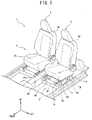
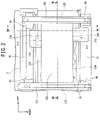
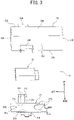
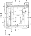
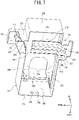
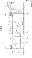
- FIGS. 1 to Figure 8 are diagrams illustrating a mounting structure of an electric component of an embodiment according to the present invention.
- up-down, front-rear and left-right directions are based on an electric component mounted on a vehicle, and it is assumed that a front-rear direction of the vehicle is the front-rear direction, a left-right direction of the vehicle (vehicle width direction) is the left-right direction and an up-down direction of the vehicle (vehicle height direction) is the up-down direction.
- a vehicle 1 includes a floor panel 2 and a vehicle room 3 is formed above the floor panel 2.
- An engine room separated from the vehicle room by a dash panel (not shown) is formed on the front side of the vehicle room 3 and a baggage compartment (not shown) is formed at the rear of the vehicle room 3.
- a driver's seat 4 in which a driver is seated and an assistant driver's seat 5 in which a passenger is seated are installed on the floor panel 2, and the driver's seat 4 is separated from the assistant driver's seat 5 in a vehicle width direction.
- the driver's seat 4 includes a seat cushion 4A that supports the driver's buttocks and thigh and a seat back 4B that receives and supports the driver's back.
- the assistant driver's seat 5 includes a seat cushion 5A that supports the passenger's buttocks and thigh, and a seat back 5B that receives and supports the passenger's back.
- An electrical apparatus 6 is installed between the seat cushion 5A of the assistant driver's seat 5 and the floor panel 2.
- both a front-side cross member 7A and a rear-side cross member 7B are attached to the floor panel 2 on the assistant driver's seat 5 side, and the front-side cross member 7A and the rear-side cross member 7B are separated in the front-rear direction and extend in the vehicle width direction.
- a left-side side sill 8A is provided at a left side end portion of the floor panel 2 and the left-side side sill 8A extends in the front-rear direction along the floor panel 2.
- a floor tunnel 8B is provided in a center part of the floor panel 2 in the vehicle width direction and the floor tunnel 8B bulges upward from the floor panel 2.
- the floor tunnel 8B is located between the driver's seat 4 and the assistant driver's seat 5 and extends in the front-rear direction along the floor panel 2.
- the electrical apparatus 6 is installed on the floor panel 2 so as to be surrounded by the front-side cross member 7A, the rear-side cross member 7B, the left-side side sill 8A and the floor tunnel 8B.
- Support brackets 9A, 9B, 9C and 9D are provided at left end and right end portions of the front-side cross member 7A and the rear-side cross member 7B respectively in the vehicle width direction and the support brackets 9A, 9B, 9C and 9D protrude upward from the front-side cross member 7A and the rear-side cross member 7B.
- a slide rail 10A is provided at upper end portions of the support brackets 9A and 9B, and the slide rail 10A extends in the front-rear direction.
- a slide rail 10B is provided at upper end portions of the support brackets 9C and 9D and the slide rail 10B extends in the front-rear direction parallel to the slide rail 10A.
- the electrical apparatus 6 is installed below the slide rails 10A and 10B.
- a pair of base frames (not shown) are provided at the bottom of the seat cushion 5A of the assistant driver's seat 5 and the base frames engage with the slide rails 10A and 10B so as to be slidable with respect to the slide rails 10A and 10B in the front-rear direction.
- the assistant driver's seat 5 moves with respect to the floor panel 2 in the front-rear direction.
- the electrical apparatus 6 includes a fixing bracket 21 that constitutes a fixing member, an electric component 22 and a resin cover member 23.
- the fixing bracket 21 includes a placement part 21A, a bifurcated fixing portion 21B, a front-side fixing portion 21C and a rear-side fixing portion 21D.
- the placement part 21A is located at a position higher than an upper surface 2a of the floor panel 2 (that is, above the upper surface 2a of the floor panel 2) and has a placement surface 21a on an upper surface thereof.
- the electric component 22 is placed on the placement surface 21a and the electric component 22 is fixed to the placement part 21A by a fixture such as a screw (not shown).
- the fixing portion 21B extends rightward linearly from the right end portion of the placement part 21A and is then bent downward.
- a bracket 11 is provided in a space surrounded by the front-side cross member 7A, the rear-side cross member 7B and the slide rails 10A and 10B, and an upper surface 11a of the bracket 11 is located at a position higher than the upper surface 2a of the floor panel 2 and at a position lower than the placement part 21A (see Figure 5 ).
- a bottom end portion of the fixing portion 21B is fixed to the upper surface 11a of the bracket 11 by a fixture such as a screw (not shown).
- the front-side fixing portion 21C includes a longitudinal wall 21e that extends upward linearly from a front end portion 21c of the placement part 21A and a lateral wall 21f that extends forward linearly from the longitudinal wall 21e and the lateral wall 21f is fixed to the front-side cross member 7A by a fixture such as a screw (not shown).
- the rear-side fixing portion 21D includes a longitudinal wall 21g that extends downward from a rear end portion 21d of the placement part 21A and a lateral wall 21h that extends rearward linearly from the longitudinal wall 21g and the lateral wall 21h is fixed to the rear-side cross member 7B by a fixture such as a screw (not shown).
- the front end portion 21c of the placement part 21A of the present embodiment constitutes one end portion of the placement part and the rear end portion 21d of the placement part 21A constitutes the other end portion of the placement part.
- the front-side cross member 7A and the rear-side cross member 7B each contain regions with different heights in the front-rear direction.
- the front-side fixing portion 21C is fixed to an upper surface 7a of the front-side cross member 7A located at a position higher than the placement surface 21a of the placement part 21A.
- the rear-side fixing portion 21D is fixed to a lower portion 7c of the rear-side cross member 7B provided at a position higher than the upper surface 2a of the floor panel 2 and lower than the placement part 21A.
- the lower portion 7c is a region lower than an upper surface 7b of the rear-side cross member 7B.
- the fixing bracket 21 is fixed to the floor panel 2 via the front-side cross member 7A, the rear-side cross member 7B and the bracket 11 such that the placement surface 21a is located at a position lower than the upper surface 7a of the front-side cross member 7A and higher than the lower portion 7c of the rear-side cross member 7B.
- the fixing bracket 21 of the present embodiment constitutes a fixing member and the front-side cross member 7A, the rear-side cross member 7B and the bracket 11 constitute a fixed part.
- the rear-side fixing portion 21D constitutes a first fixing portion and the front-side fixing portion 21C constitutes a second fixing portion.
- the rear-side cross member 7B constitutes a fixed part and a first fixed part, the lower portion 7c of the rear-side cross member 7B constitutes a first fixed region.
- the front-side cross member 7A constitutes a fixed part and a second fixed part and the upper surface 7a of the front-side cross member 7A constitutes a second fixed region.
- the cover member 23 includes a ceiling wall 23A, a front wall 23B, a rear wall 23C, a left side wall 23D and a right side wall 23E.
- the front wall 23B and the rear wall 23C extend downward from the ceiling wall 23A and face each other in the front-rear direction.
- the left side wall 23D extends downward from the ceiling wall 23A and communicates the left end portion of the front wall 23B with the left end portion of the rear wall 23C.
- the right side wall 23E extends downward from the ceiling wall 23A and communicates the right end portion of the front wall 23B with the right end portion of the rear wall 23C.
- the bottom of the front wall 23B, the rear wall 23C, the left side wall 23D and the right side wall 23E is open.
- the cover member 23 covers the fixing bracket 21 and the electric component 22 with the ceiling wall 23A, the front wall 23B, the rear wall 23C, the left side wall 23D and the right side wall 23E from above and from the side (in a front to rear direction and a left to right direction).
- the cover member 23 covers the fixing bracket 21 and the electric component 22 to ensure that the fixing bracket 21 and the electric component 22 are not visible from the outside.
- the lengths of the left side wall 23D and the right side wall 23E in the vehicle width direction are shorter, and the cover member 23 is formed in a rectangular shape when viewed from above.
- the lengths (heights) of the front wall 23B, the rear wall 23C, the left side wall 23D and the right side wall 23E in the up-down direction are formed identically and a bottom end portion 23a of the front wall 23B, the rear wall 23C, the left side wall 23D and the right side wall 23E is located at a position lower than the placement surface 21a of the fixing bracket 21 (see Figure 5 ).
- the bottom end portion 23a of the front wall 23B, the rear wall 23C, the left side wall 23D and the right side wall 23E is also referred to as the bottom end portion 23a of the cover member 23.
- the bottom end portion 23a of the cover member 23 is in contact with the upper surface 2a of the floor panel 2 and is located at the same height position as that of the upper surface 2a of the floor panel 2.
- a front-side opening 23b is formed in the front wall 23B of the cover member 23 and the front-side opening 23b is cut out upward from the bottom end portion 23a of the front wall 23B. That is, the front-side opening 23b is open in the up-down direction of the front wall 23B.
- a rear-side opening 23c is formed in the rear wall 23C of the cover member 23 and the rear-side opening 23c is cut out upward from the bottom end portion 23a of the rear wall 23C. That is, the rear-side opening 23c is open in the up-down direction of the rear wall 23C.
- an upper end portion 23d of the front-side opening 23b is located above an upper end portion 23e of the rear-side opening 23c. More specifically, the upper end portion 23e of the rear-side opening 23c is located at the same height position as that of the placement surface 21a of the placement part 21A and the upper end portion 23d of the front-side opening 23b is located above the placement surface 21a of the placement part 21A and near the ceiling wall 23A.
- the lateral wall 21f of the front-side fixing portion 21C is located at a position higher than the lateral wall 21h of the rear-side fixing portion 21D and extends from the front end portion 21c of the placement part 21A through the front-side opening 23b forward (outward) from the front wall 23B.
- the lateral wall 21h of the rear-side fixing portion 21D is located at a position lower than the lateral wall 21f of the front-side fixing portion 21C and extends from the rear end portion 21d of the placement part 21A through the rear-side opening 23c rearward (outward) from the rear wall 23C.
- the cover member 23 covers the fixing bracket 21 and the electric component 22 from above and from the side, the front-side fixing portion 21C and the rear-side fixing portion 21D are inserted through the front-side opening 23b and the rear-side opening 23c, and the front-side opening 23b and the rear-side opening 23c are guided downward along the front-side fixing portion 21C and the rear-side fixing portion 21D.
- the lateral wall 21f of the front-side fixing portion 21C never comes into contact with the upper end portion 23d of the front-side opening 23b and the cover member 23 is allowed to move until the bottom end portion 23a of the cover member 23 comes into contact with the floor panel 2.
- the front wall 23B is provided with protruding walls 23F, 23G and 23H.
- the protruding walls 23F and 23G protrude forward from left and right edges of the front-side opening 23b and face each other in the vehicle width direction.
- the protruding wall 23H protrudes forward from the upper edge of the upper end portion 23d of the front-side opening 23b and covers the lateral wall 21f of the front-side fixing portion 21C from above (see Figure 2 and Figure 5 ).
- the distal ends of the protruding walls 23F and 23G in the protruding direction are in contact with the front-side cross member 7A and the protruding wall 23H is in contact with the upper surface 7a of the front-side cross member 7A (see Figure 5 ).
- the front-side opening 23b is closed by the protruding walls 23F, 23G and 23H and the front-side cross member 7A, and an internal space 24 of the cover member 23 (see Figure 5 ) is out of communication with the outside (outside air) of the cover member 23 via the front-side opening 23b.
- the rear wall 23C of the cover member 23 is provided with protruding walls 231, 23J and 23K.
- the protruding walls 231 and 23J protrude rearward from left and right edges of the rear-side opening 23c and face each other in the vehicle width direction.
- the protruding wall 23K protrudes rearward from an upper edge of the upper end portion 23d of the rear-side opening 23c and covers a lateral wall 21h of the rear-side fixing portion 21D from above (see Figure 2 and Figure 5 ).
- the distal ends of the protruding walls 231 and 23J in the protruding direction are in contact with the rear-side cross member 7B and the protruding wall 23K is in contact with the upper surface 7b of the rear-side cross member 7B (see Figure 5 ).
- the rear-side opening 23c is closed by the protruding walls 231, 23J and 23K and the rear-side cross member 7B, and the internal space 24 of the cover member 23 is out of communication with the outside (outside air) of the cover member 23 via the rear-side opening 23c.
- the front wall 23B of the cover member 23 is provided with a partition wall 23W.
- the partition wall 23W closes an upper side portion of the front-side opening 23b (see Figure 8 ).
- a bottom end portion 23f of the partition wall 23W is located at the same height position as that of the placement surface 21a (see Figure 8 ) and an air space is formed in an upper internal space 25 of the cover member 23 above the placement surface 21a of the internal space 24 of the cover member 23.
- the partition wall 23W may close the entire front-side opening 23b.
- An air space is also formed in a lower side internal space 26 below the placement part 21A of the internal space 24 of the cover member 23.
- the front wall 23B, the rear wall 23C, the left side wall 23D and the right side wall 23E of the cover member 23 of the present embodiment constitute side walls and the front wall 23B constitutes a predetermined side wall.
- Engaging parts are formed on both the left and right sides of the partition wall 23W and both the left and right sides of the longitudinal wall 21e of the front-side fixing portion 21C strongly engage with the engaging parts. In this way, the cover member 23 is fixed to the fixing bracket 21.
- the lateral wall 21f of the front-side fixing portion 21C engages with the front-side opening 23b and the lateral wall 21h of the rear-side fixing portion 21D engages with the rear-side opening 23c.
- the distal ends of the protruding walls 23F and 23G in the protruding direction come into contact with the front-side cross member 7A and the protruding wall 23H comes into contact with the upper surface 7a of the front-side cross member 7A.
- the distal ends of the protruding walls 231 and 23J in the protruding direction come into contact with the rear-side cross member 7B and the protruding wall 23K is in contact with the upper surface 7b of the rear-side cross member 7B.
- the cover member 23 is stably fixed to the fixing bracket 21 without moving with respect to the floor panel 2.
- a plurality of through holes 23g and 23h for passing wire harnesses are formed in the right side wall 23E of the cover member 23.
- the through holes 23g and 23h are located at positions lower than the placement surface 21a of the placement part 21A.
- the wire harnesses are connected to terminals of the electric component 22, wired to the outside of the cover member 23 from the terminal of the electric component 22 through the bifurcated fixing portion 21B and the through holes 23g and 23h and connected to another electric component mounted on the vehicle 1.
- the wire harnesses pass below the floor tunnel 8B and are disposed from below the driver's seat 4 to the lower side of the assistant driver's seat 5.
- the through holes for passing the wire harnesses may be formed in any one of the front wall 23B, the rear wall 23C and the left side wall 23D, the through holes are preferably located at positions lower than the placement surface 21a of the placement part 21A in this case.
- the electrical apparatus 6 of the present embodiment is installed between the seat cushion 5A of the assistant driver's seat 5 and the floor panel 2, it is possible to install the electrical apparatus 6 in the vehicle room 3 in a lower temperature environment than in the engine room and more easily extract the performance of the electric component 22.
- the electric apparatus 6 When the electric apparatus 6 is installed on the upper surface 2a of the floor panel 2, the electric apparatus 6 is installed at a low position, and therefore the electric component 22 installed on the floor panel 2 may become submerged while the vehicle 1 is running or parked on a submerged road.
- the mounting structure for the electric component 22 of the present embodiment is provided with the fixing bracket 21 including the placement part 21A with the placement surface 21a on which the electric component 22 is mounted, and the fixing bracket 21 is fixed to the front-side fixing part 21C, the rear-side fixing part 21D and the bracket 11 provided on the upper surface 2a of the floor panel 2 of the vehicle 1.
- the mounting structure for the electric component 22 is provided with the cover member 23 including the ceiling wall 23A, and the front wall 23B, the rear wall 23C, the left side wall 23D and the right side wall 23E extending downward from the ceiling wall 23A, the cover member 23 being configured to cover the fixing bracket 21 and the electric component 22 from above and from the side.
- the placement surface 21a of the fixing bracket 21 is located at a position higher than the upper surface 2a of the floor panel 2, and the bottom end portion 23a of the front wall 23B, the rear wall 23C, the left side wall 23D and the right side wall 23E in the cover member 23 is located at a position lower than the placement surface 21a.
- the placement surface 21a on which the electric component 22 is mounted is separated upward from the upper surface 2a of the floor panel 2 and the electric component 22 is installed on the upper internal space 25, it is possible to prevent water from reaching the electric component 22 if the water level rises when the vehicle 1 is submerged.
- the air space formed in the upper internal space 25 prevents the water from reaching the electric component 22 and prevents the electric component 22 installed on the floor panel 2 from submerging.
- the placement surface 21a of the placement part 21A on which the electric component 22 is mounted is installed separated upward from the upper surface 2a of the floor panel 2, and it is thereby possible to form an air space in the lower internal space 26 of the cover member 23 and thereby allow the heat of the electric component 22 to escape to the lower internal space 26. This makes it possible to improve heat discharge performance of the electric component 22 and prevent temperature rise of the electric component 22.
- the cover member 23 includes the front-side cross member 7A and the rear-side cross member 7B located at positions higher than the upper surface 2a of the floor panel 2.
- the front-side cross member 7A includes the upper surface 7a to which the front-side fixing part 21C is fixed and the rear-side cross member 7B includes the lower part 7c to which the rear-side fixing part 21D is fixed.
- the placement surface 21a is installed at a position higher than the lower part 7c of the rear-side cross member 7B.
- the front-side opening 23b is provided on the front wall 23B of the cover member 23, and the front-side opening 23b is open in the up-down direction so that the upper end portion 23d is located above the placement surface 21a.
- the rear-side cross member 7B extends rearward from the rear end portion 21d of the placement part 21A through the rear-side opening 23c behind the rear wall 23C, and the front-side cross member 7A extends from the front end portion 21c of the placement part 21A through the front-side opening 23b outward from the front wall 23B so that the lateral wall 21f is located at a position higher than the lateral wall 21h of the rear-side cross member 7B.
- the partition wall 23W is provided on the front wall 23B and the partition wall 23W closes the upper part of the front-side opening 23b at a position higher than the placement surface 21a.
- the internal space 24 communicates with an outside of the cover member 23 through the front-side opening 23b.
- the partition wall 23W is provided on the front wall 23B and the partition wall 23W closes the upper part of the front-side opening 23b at a position higher than the placement surface 21a.
- the air space formed in the upper internal space 25 can prevent water from reaching the electric component 22 and prevent the electric component 22 installed on the floor panel 2 from submerging.
- the front-side fixing part 21C is installed at a position higher than the placement surface 21a of the placement part 21A
- the rear-side fixing part 21D is installed at a position lower than the placement surface 21a of the placement part 21A
- the placement surface 21a is installed at a position higher than the rear-side fixing part 21D, but the present invention is not limited to this.
- the front-side fixing part 21C may be installed at a position lower than the placement surface 21a of the placement part 21A
- the rear-side fixing part 21D may be installed at a position higher than the placement surface 21a of the placement part 21A
- the placement surface 21a may be installed at a position higher than the front-side fixing part 21C.
- the mounting structure for the electric component 22 of the present embodiment includes the wire harness connected to the electric component 22.
- the cover member 23 contains the through holes 23g and 23h through which the wire harness is passed inside the cover member 23, and the through holes 23g and 23h are formed on the right side wall 23E so as to be located at a position lower than the placement surface 21a.
- the upper internal space 25 may communicate with the outside of the cover member 23 through the through hole.
- the through holes 23g and 23h are formed at positions lower than the placement surface 21a, it is possible to prevent the upper internal space 25 from communicating with the outside of the cover member 23 through the through holes 23g and 23h, and prevent a connection part between the electric component 22 and the wire harness from submerging.
- the position of the placement part 21A is made higher, it is possible to increase the installation areas of the front wall 23B, the rear wall 23C, the left side wall 23D and the right side wall 23E below the placement part 21A, increase the installation spaces of the through holes 23g and 23h and improve a degree of freedom of installation of the through holes 23g and 23h.
- the fixed part of the present embodiment is constructed of the front-side cross member 7A and the rear-side cross member 7B of the floor panel 2, the fixed part may be a region integral with the floor panel 2 (integrally molded).
- the electric component is applicable, for example, to a battery or a DC-DC converter.
- the electric component is not limited to a battery or a DC-DC converter, but may be applicable to any electrical component as long as it is mounted on the vehicle 1.
- the electrical apparatus 6 is installed between the seat cushion 5A of the assistant driver's seat 5 and the floor panel 2, the electrical apparatus 6 may be installed between the seat cushion 4A of the driver's seat 4 and the floor panel 2.
Landscapes
- Engineering & Computer Science (AREA)
- Chemical & Material Sciences (AREA)
- Combustion & Propulsion (AREA)
- Transportation (AREA)
- Mechanical Engineering (AREA)
- Body Structure For Vehicles (AREA)
- Arrangement Or Mounting Of Propulsion Units For Vehicles (AREA)
Applications Claiming Priority (1)
| Application Number | Priority Date | Filing Date | Title |
|---|---|---|---|
| JP2021006978A JP7552375B2 (ja) | 2021-01-20 | 2021-01-20 | 電装部品の取付構造 |
Publications (2)
| Publication Number | Publication Date |
|---|---|
| EP4032734A1 true EP4032734A1 (fr) | 2022-07-27 |
| EP4032734B1 EP4032734B1 (fr) | 2023-06-14 |
Family
ID=78918553
Family Applications (1)
| Application Number | Title | Priority Date | Filing Date |
|---|---|---|---|
| EP21215314.2A Active EP4032734B1 (fr) | 2021-01-20 | 2021-12-16 | Structure de montage pour composant électrique |
Country Status (2)
| Country | Link |
|---|---|
| EP (1) | EP4032734B1 (fr) |
| JP (1) | JP7552375B2 (fr) |
Families Citing this family (1)
| Publication number | Priority date | Publication date | Assignee | Title |
|---|---|---|---|---|
| JP7678018B2 (ja) * | 2023-03-23 | 2025-05-15 | ダイハツ工業株式会社 | ブロワブラケット構造 |
Citations (4)
| Publication number | Priority date | Publication date | Assignee | Title |
|---|---|---|---|---|
| JP2009035126A (ja) | 2007-08-01 | 2009-02-19 | Isuzu Motors Ltd | ハイブリッド電気自動車のバッテリボックス構造 |
| WO2013061847A1 (fr) * | 2011-10-28 | 2013-05-02 | 本田技研工業株式会社 | Structure de montage pour batterie alimentant un véhicule |
| EP2620353A1 (fr) * | 2010-11-10 | 2013-07-31 | Honda Motor Co., Ltd. | Structure de plancher d'automobile |
| US20200119321A1 (en) * | 2018-10-11 | 2020-04-16 | Honda Motor Co., Ltd. | Battery pack for electric vehicle |
Family Cites Families (2)
| Publication number | Priority date | Publication date | Assignee | Title |
|---|---|---|---|---|
| JPWO2017073416A1 (ja) * | 2015-10-30 | 2018-08-30 | 日立オートモティブシステムズ株式会社 | 蓄電装置 |
| JP7032269B2 (ja) * | 2018-08-31 | 2022-03-08 | 本田技研工業株式会社 | 電動車両のバッテリパック |
-
2021
- 2021-01-20 JP JP2021006978A patent/JP7552375B2/ja active Active
- 2021-12-16 EP EP21215314.2A patent/EP4032734B1/fr active Active
Patent Citations (4)
| Publication number | Priority date | Publication date | Assignee | Title |
|---|---|---|---|---|
| JP2009035126A (ja) | 2007-08-01 | 2009-02-19 | Isuzu Motors Ltd | ハイブリッド電気自動車のバッテリボックス構造 |
| EP2620353A1 (fr) * | 2010-11-10 | 2013-07-31 | Honda Motor Co., Ltd. | Structure de plancher d'automobile |
| WO2013061847A1 (fr) * | 2011-10-28 | 2013-05-02 | 本田技研工業株式会社 | Structure de montage pour batterie alimentant un véhicule |
| US20200119321A1 (en) * | 2018-10-11 | 2020-04-16 | Honda Motor Co., Ltd. | Battery pack for electric vehicle |
Also Published As
| Publication number | Publication date |
|---|---|
| EP4032734B1 (fr) | 2023-06-14 |
| JP7552375B2 (ja) | 2024-09-18 |
| JP2022111515A (ja) | 2022-08-01 |
Similar Documents
| Publication | Publication Date | Title |
|---|---|---|
| US10434897B2 (en) | Vehicle high-voltage system equipment unit, vehicle battery unit and vehicle | |
| EP2772394B1 (fr) | Structure de couverture protectrice de câblage pour véhicule électrique | |
| JP4363350B2 (ja) | 二次電池の冷却構造 | |
| EP2899073A1 (fr) | Structure de guidage de fils couplés pour un véhicule électrique | |
| RU2011139135A (ru) | Конструкция для установки аккумуляторов транспортного средства | |
| KR101561045B1 (ko) | 전원 연결 박스 | |
| CN102652073A (zh) | 蓄电装置的冷却结构 | |
| CN105730184B (zh) | 电力控制单元及电气器件 | |
| CN110809525A (zh) | 进气格栅及车辆 | |
| KR20110001012A (ko) | 전원 연결 박스 | |
| EP1977933B1 (fr) | Structure pour monter un composant electrique | |
| EP4032734B1 (fr) | Structure de montage pour composant électrique | |
| EP3782835B1 (fr) | Bloc-batterie de véhicule | |
| US20230339410A1 (en) | Support structure for on-vehicle high voltage component | |
| KR102719106B1 (ko) | 차량용 고전압 배터리 캐리어 | |
| JP2019051888A (ja) | 電気駆動車両構造 | |
| US12539768B2 (en) | Electric power supplying module | |
| CN106394215A (zh) | 车辆 | |
| EP4035917A1 (fr) | Structure d'isolation thermique d'un composant électrique | |
| CN111661166B (zh) | 车辆前部结构 | |
| JP4692203B2 (ja) | 電気部品の取り付け構造および電気部品の取り付け方法 | |
| JP2020155341A (ja) | バッテリパック冷却構造 | |
| US20260027924A1 (en) | Charging box | |
| CN222966664U (zh) | 一种车辆及其线束导向结构 | |
| CN115402231B (zh) | 集成式电气组合支架及车辆 |
Legal Events
| Date | Code | Title | Description |
|---|---|---|---|
| PUAI | Public reference made under article 153(3) epc to a published international application that has entered the european phase |
Free format text: ORIGINAL CODE: 0009012 |
|
| STAA | Information on the status of an ep patent application or granted ep patent |
Free format text: STATUS: REQUEST FOR EXAMINATION WAS MADE |
|
| 17P | Request for examination filed |
Effective date: 20211216 |
|
| AK | Designated contracting states |
Kind code of ref document: A1 Designated state(s): AL AT BE BG CH CY CZ DE DK EE ES FI FR GB GR HR HU IE IS IT LI LT LU LV MC MK MT NL NO PL PT RO RS SE SI SK SM TR |
|
| GRAP | Despatch of communication of intention to grant a patent |
Free format text: ORIGINAL CODE: EPIDOSNIGR1 |
|
| STAA | Information on the status of an ep patent application or granted ep patent |
Free format text: STATUS: GRANT OF PATENT IS INTENDED |
|
| INTG | Intention to grant announced |
Effective date: 20230316 |
|
| GRAS | Grant fee paid |
Free format text: ORIGINAL CODE: EPIDOSNIGR3 |
|
| GRAA | (expected) grant |
Free format text: ORIGINAL CODE: 0009210 |
|
| STAA | Information on the status of an ep patent application or granted ep patent |
Free format text: STATUS: THE PATENT HAS BEEN GRANTED |
|
| AK | Designated contracting states |
Kind code of ref document: B1 Designated state(s): AL AT BE BG CH CY CZ DE DK EE ES FI FR GB GR HR HU IE IS IT LI LT LU LV MC MK MT NL NO PL PT RO RS SE SI SK SM TR |
|
| REG | Reference to a national code |
Ref country code: CH Ref legal event code: EP |
|
| REG | Reference to a national code |
Ref country code: DE Ref legal event code: R096 Ref document number: 602021002944 Country of ref document: DE |
|
| REG | Reference to a national code |
Ref country code: AT Ref legal event code: REF Ref document number: 1578993 Country of ref document: AT Kind code of ref document: T Effective date: 20230715 |
|
| REG | Reference to a national code |
Ref country code: LT Ref legal event code: MG9D |
|
| REG | Reference to a national code |
Ref country code: NL Ref legal event code: MP Effective date: 20230614 |
|
| PG25 | Lapsed in a contracting state [announced via postgrant information from national office to epo] |
Ref country code: SE Free format text: LAPSE BECAUSE OF FAILURE TO SUBMIT A TRANSLATION OF THE DESCRIPTION OR TO PAY THE FEE WITHIN THE PRESCRIBED TIME-LIMIT Effective date: 20230614 Ref country code: NO Free format text: LAPSE BECAUSE OF FAILURE TO SUBMIT A TRANSLATION OF THE DESCRIPTION OR TO PAY THE FEE WITHIN THE PRESCRIBED TIME-LIMIT Effective date: 20230914 Ref country code: ES Free format text: LAPSE BECAUSE OF FAILURE TO SUBMIT A TRANSLATION OF THE DESCRIPTION OR TO PAY THE FEE WITHIN THE PRESCRIBED TIME-LIMIT Effective date: 20230614 |
|
| REG | Reference to a national code |
Ref country code: AT Ref legal event code: MK05 Ref document number: 1578993 Country of ref document: AT Kind code of ref document: T Effective date: 20230614 |
|
| PG25 | Lapsed in a contracting state [announced via postgrant information from national office to epo] |
Ref country code: RS Free format text: LAPSE BECAUSE OF FAILURE TO SUBMIT A TRANSLATION OF THE DESCRIPTION OR TO PAY THE FEE WITHIN THE PRESCRIBED TIME-LIMIT Effective date: 20230614 Ref country code: NL Free format text: LAPSE BECAUSE OF FAILURE TO SUBMIT A TRANSLATION OF THE DESCRIPTION OR TO PAY THE FEE WITHIN THE PRESCRIBED TIME-LIMIT Effective date: 20230614 Ref country code: LV Free format text: LAPSE BECAUSE OF FAILURE TO SUBMIT A TRANSLATION OF THE DESCRIPTION OR TO PAY THE FEE WITHIN THE PRESCRIBED TIME-LIMIT Effective date: 20230614 Ref country code: LT Free format text: LAPSE BECAUSE OF FAILURE TO SUBMIT A TRANSLATION OF THE DESCRIPTION OR TO PAY THE FEE WITHIN THE PRESCRIBED TIME-LIMIT Effective date: 20230614 Ref country code: HR Free format text: LAPSE BECAUSE OF FAILURE TO SUBMIT A TRANSLATION OF THE DESCRIPTION OR TO PAY THE FEE WITHIN THE PRESCRIBED TIME-LIMIT Effective date: 20230614 Ref country code: GR Free format text: LAPSE BECAUSE OF FAILURE TO SUBMIT A TRANSLATION OF THE DESCRIPTION OR TO PAY THE FEE WITHIN THE PRESCRIBED TIME-LIMIT Effective date: 20230915 |
|
| PG25 | Lapsed in a contracting state [announced via postgrant information from national office to epo] |
Ref country code: FI Free format text: LAPSE BECAUSE OF FAILURE TO SUBMIT A TRANSLATION OF THE DESCRIPTION OR TO PAY THE FEE WITHIN THE PRESCRIBED TIME-LIMIT Effective date: 20230614 |
|
| PG25 | Lapsed in a contracting state [announced via postgrant information from national office to epo] |
Ref country code: SK Free format text: LAPSE BECAUSE OF FAILURE TO SUBMIT A TRANSLATION OF THE DESCRIPTION OR TO PAY THE FEE WITHIN THE PRESCRIBED TIME-LIMIT Effective date: 20230614 |
|
| PG25 | Lapsed in a contracting state [announced via postgrant information from national office to epo] |
Ref country code: IS Free format text: LAPSE BECAUSE OF FAILURE TO SUBMIT A TRANSLATION OF THE DESCRIPTION OR TO PAY THE FEE WITHIN THE PRESCRIBED TIME-LIMIT Effective date: 20231014 |
|
| PG25 | Lapsed in a contracting state [announced via postgrant information from national office to epo] |
Ref country code: SM Free format text: LAPSE BECAUSE OF FAILURE TO SUBMIT A TRANSLATION OF THE DESCRIPTION OR TO PAY THE FEE WITHIN THE PRESCRIBED TIME-LIMIT Effective date: 20230614 Ref country code: SK Free format text: LAPSE BECAUSE OF FAILURE TO SUBMIT A TRANSLATION OF THE DESCRIPTION OR TO PAY THE FEE WITHIN THE PRESCRIBED TIME-LIMIT Effective date: 20230614 Ref country code: RO Free format text: LAPSE BECAUSE OF FAILURE TO SUBMIT A TRANSLATION OF THE DESCRIPTION OR TO PAY THE FEE WITHIN THE PRESCRIBED TIME-LIMIT Effective date: 20230614 Ref country code: PT Free format text: LAPSE BECAUSE OF FAILURE TO SUBMIT A TRANSLATION OF THE DESCRIPTION OR TO PAY THE FEE WITHIN THE PRESCRIBED TIME-LIMIT Effective date: 20231016 Ref country code: IS Free format text: LAPSE BECAUSE OF FAILURE TO SUBMIT A TRANSLATION OF THE DESCRIPTION OR TO PAY THE FEE WITHIN THE PRESCRIBED TIME-LIMIT Effective date: 20231014 Ref country code: EE Free format text: LAPSE BECAUSE OF FAILURE TO SUBMIT A TRANSLATION OF THE DESCRIPTION OR TO PAY THE FEE WITHIN THE PRESCRIBED TIME-LIMIT Effective date: 20230614 Ref country code: CZ Free format text: LAPSE BECAUSE OF FAILURE TO SUBMIT A TRANSLATION OF THE DESCRIPTION OR TO PAY THE FEE WITHIN THE PRESCRIBED TIME-LIMIT Effective date: 20230614 Ref country code: AT Free format text: LAPSE BECAUSE OF FAILURE TO SUBMIT A TRANSLATION OF THE DESCRIPTION OR TO PAY THE FEE WITHIN THE PRESCRIBED TIME-LIMIT Effective date: 20230614 |
|
| PG25 | Lapsed in a contracting state [announced via postgrant information from national office to epo] |
Ref country code: PL Free format text: LAPSE BECAUSE OF FAILURE TO SUBMIT A TRANSLATION OF THE DESCRIPTION OR TO PAY THE FEE WITHIN THE PRESCRIBED TIME-LIMIT Effective date: 20230614 |
|
| REG | Reference to a national code |
Ref country code: DE Ref legal event code: R097 Ref document number: 602021002944 Country of ref document: DE |
|
| PLBE | No opposition filed within time limit |
Free format text: ORIGINAL CODE: 0009261 |
|
| STAA | Information on the status of an ep patent application or granted ep patent |
Free format text: STATUS: NO OPPOSITION FILED WITHIN TIME LIMIT |
|
| PG25 | Lapsed in a contracting state [announced via postgrant information from national office to epo] |
Ref country code: DK Free format text: LAPSE BECAUSE OF FAILURE TO SUBMIT A TRANSLATION OF THE DESCRIPTION OR TO PAY THE FEE WITHIN THE PRESCRIBED TIME-LIMIT Effective date: 20230614 |
|
| PG25 | Lapsed in a contracting state [announced via postgrant information from national office to epo] |
Ref country code: SI Free format text: LAPSE BECAUSE OF FAILURE TO SUBMIT A TRANSLATION OF THE DESCRIPTION OR TO PAY THE FEE WITHIN THE PRESCRIBED TIME-LIMIT Effective date: 20230614 |
|
| 26N | No opposition filed |
Effective date: 20240315 |
|
| PG25 | Lapsed in a contracting state [announced via postgrant information from national office to epo] |
Ref country code: SI Free format text: LAPSE BECAUSE OF FAILURE TO SUBMIT A TRANSLATION OF THE DESCRIPTION OR TO PAY THE FEE WITHIN THE PRESCRIBED TIME-LIMIT Effective date: 20230614 Ref country code: IT Free format text: LAPSE BECAUSE OF FAILURE TO SUBMIT A TRANSLATION OF THE DESCRIPTION OR TO PAY THE FEE WITHIN THE PRESCRIBED TIME-LIMIT Effective date: 20230614 |
|
| PG25 | Lapsed in a contracting state [announced via postgrant information from national office to epo] |
Ref country code: LU Free format text: LAPSE BECAUSE OF NON-PAYMENT OF DUE FEES Effective date: 20231216 |
|
| PG25 | Lapsed in a contracting state [announced via postgrant information from national office to epo] |
Ref country code: MC Free format text: LAPSE BECAUSE OF FAILURE TO SUBMIT A TRANSLATION OF THE DESCRIPTION OR TO PAY THE FEE WITHIN THE PRESCRIBED TIME-LIMIT Effective date: 20230614 |
|
| REG | Reference to a national code |
Ref country code: BE Ref legal event code: MM Effective date: 20231231 |
|
| PG25 | Lapsed in a contracting state [announced via postgrant information from national office to epo] |
Ref country code: MC Free format text: LAPSE BECAUSE OF FAILURE TO SUBMIT A TRANSLATION OF THE DESCRIPTION OR TO PAY THE FEE WITHIN THE PRESCRIBED TIME-LIMIT Effective date: 20230614 Ref country code: LU Free format text: LAPSE BECAUSE OF NON-PAYMENT OF DUE FEES Effective date: 20231216 |
|
| REG | Reference to a national code |
Ref country code: IE Ref legal event code: MM4A |
|
| PG25 | Lapsed in a contracting state [announced via postgrant information from national office to epo] |
Ref country code: IE Free format text: LAPSE BECAUSE OF NON-PAYMENT OF DUE FEES Effective date: 20231216 |
|
| PG25 | Lapsed in a contracting state [announced via postgrant information from national office to epo] |
Ref country code: BE Free format text: LAPSE BECAUSE OF NON-PAYMENT OF DUE FEES Effective date: 20231231 |
|
| PG25 | Lapsed in a contracting state [announced via postgrant information from national office to epo] |
Ref country code: IE Free format text: LAPSE BECAUSE OF NON-PAYMENT OF DUE FEES Effective date: 20231216 Ref country code: BE Free format text: LAPSE BECAUSE OF NON-PAYMENT OF DUE FEES Effective date: 20231231 |
|
| PG25 | Lapsed in a contracting state [announced via postgrant information from national office to epo] |
Ref country code: BG Free format text: LAPSE BECAUSE OF FAILURE TO SUBMIT A TRANSLATION OF THE DESCRIPTION OR TO PAY THE FEE WITHIN THE PRESCRIBED TIME-LIMIT Effective date: 20230614 |
|
| PG25 | Lapsed in a contracting state [announced via postgrant information from national office to epo] |
Ref country code: BG Free format text: LAPSE BECAUSE OF FAILURE TO SUBMIT A TRANSLATION OF THE DESCRIPTION OR TO PAY THE FEE WITHIN THE PRESCRIBED TIME-LIMIT Effective date: 20230614 |
|
| PG25 | Lapsed in a contracting state [announced via postgrant information from national office to epo] |
Ref country code: CY Free format text: LAPSE BECAUSE OF FAILURE TO SUBMIT A TRANSLATION OF THE DESCRIPTION OR TO PAY THE FEE WITHIN THE PRESCRIBED TIME-LIMIT; INVALID AB INITIO Effective date: 20211216 |
|
| REG | Reference to a national code |
Ref country code: CH Ref legal event code: PL |
|
| PG25 | Lapsed in a contracting state [announced via postgrant information from national office to epo] |
Ref country code: CH Free format text: LAPSE BECAUSE OF NON-PAYMENT OF DUE FEES Effective date: 20241231 |
|
| PG25 | Lapsed in a contracting state [announced via postgrant information from national office to epo] |
Ref country code: TR Free format text: LAPSE BECAUSE OF FAILURE TO SUBMIT A TRANSLATION OF THE DESCRIPTION OR TO PAY THE FEE WITHIN THE PRESCRIBED TIME-LIMIT Effective date: 20230614 |
|
| PGFP | Annual fee paid to national office [announced via postgrant information from national office to epo] |
Ref country code: DE Payment date: 20251028 Year of fee payment: 5 |
|
| PGFP | Annual fee paid to national office [announced via postgrant information from national office to epo] |
Ref country code: FR Payment date: 20251110 Year of fee payment: 5 |