EP4032762A1 - Agencement de freinage pour véhicule - Google Patents
Agencement de freinage pour véhicule Download PDFInfo
- Publication number
- EP4032762A1 EP4032762A1 EP21216794.4A EP21216794A EP4032762A1 EP 4032762 A1 EP4032762 A1 EP 4032762A1 EP 21216794 A EP21216794 A EP 21216794A EP 4032762 A1 EP4032762 A1 EP 4032762A1
- Authority
- EP
- European Patent Office
- Prior art keywords
- brake
- source
- pressurized air
- arrangement
- vehicle
- Prior art date
- Legal status (The legal status is an assumption and is not a legal conclusion. Google has not performed a legal analysis and makes no representation as to the accuracy of the status listed.)
- Granted
Links
Images



Classifications
-
- B—PERFORMING OPERATIONS; TRANSPORTING
- B60—VEHICLES IN GENERAL
- B60T—VEHICLE BRAKE CONTROL SYSTEMS OR PARTS THEREOF; BRAKE CONTROL SYSTEMS OR PARTS THEREOF, IN GENERAL; ARRANGEMENT OF BRAKING ELEMENTS ON VEHICLES IN GENERAL; PORTABLE DEVICES FOR PREVENTING UNWANTED MOVEMENT OF VEHICLES; VEHICLE MODIFICATIONS TO FACILITATE COOLING OF BRAKES
- B60T13/00—Transmitting braking action from initiating means to ultimate brake actuator with power assistance or drive; Brake systems incorporating such transmitting means, e.g. air-pressure brake systems
- B60T13/10—Transmitting braking action from initiating means to ultimate brake actuator with power assistance or drive; Brake systems incorporating such transmitting means, e.g. air-pressure brake systems with fluid assistance, drive, or release
- B60T13/66—Electrical control in fluid-pressure brake systems
- B60T13/68—Electrical control in fluid-pressure brake systems by electrically-controlled valves
- B60T13/683—Electrical control in fluid-pressure brake systems by electrically-controlled valves in pneumatic systems or parts thereof
-
- B—PERFORMING OPERATIONS; TRANSPORTING
- B60—VEHICLES IN GENERAL
- B60T—VEHICLE BRAKE CONTROL SYSTEMS OR PARTS THEREOF; BRAKE CONTROL SYSTEMS OR PARTS THEREOF, IN GENERAL; ARRANGEMENT OF BRAKING ELEMENTS ON VEHICLES IN GENERAL; PORTABLE DEVICES FOR PREVENTING UNWANTED MOVEMENT OF VEHICLES; VEHICLE MODIFICATIONS TO FACILITATE COOLING OF BRAKES
- B60T13/00—Transmitting braking action from initiating means to ultimate brake actuator with power assistance or drive; Brake systems incorporating such transmitting means, e.g. air-pressure brake systems
- B60T13/10—Transmitting braking action from initiating means to ultimate brake actuator with power assistance or drive; Brake systems incorporating such transmitting means, e.g. air-pressure brake systems with fluid assistance, drive, or release
- B60T13/24—Transmitting braking action from initiating means to ultimate brake actuator with power assistance or drive; Brake systems incorporating such transmitting means, e.g. air-pressure brake systems with fluid assistance, drive, or release the fluid being gaseous
-
- B—PERFORMING OPERATIONS; TRANSPORTING
- B60—VEHICLES IN GENERAL
- B60T—VEHICLE BRAKE CONTROL SYSTEMS OR PARTS THEREOF; BRAKE CONTROL SYSTEMS OR PARTS THEREOF, IN GENERAL; ARRANGEMENT OF BRAKING ELEMENTS ON VEHICLES IN GENERAL; PORTABLE DEVICES FOR PREVENTING UNWANTED MOVEMENT OF VEHICLES; VEHICLE MODIFICATIONS TO FACILITATE COOLING OF BRAKES
- B60T13/00—Transmitting braking action from initiating means to ultimate brake actuator with power assistance or drive; Brake systems incorporating such transmitting means, e.g. air-pressure brake systems
- B60T13/10—Transmitting braking action from initiating means to ultimate brake actuator with power assistance or drive; Brake systems incorporating such transmitting means, e.g. air-pressure brake systems with fluid assistance, drive, or release
- B60T13/66—Electrical control in fluid-pressure brake systems
- B60T13/662—Electrical control in fluid-pressure brake systems characterised by specified functions of the control system components
-
- B—PERFORMING OPERATIONS; TRANSPORTING
- B60—VEHICLES IN GENERAL
- B60T—VEHICLE BRAKE CONTROL SYSTEMS OR PARTS THEREOF; BRAKE CONTROL SYSTEMS OR PARTS THEREOF, IN GENERAL; ARRANGEMENT OF BRAKING ELEMENTS ON VEHICLES IN GENERAL; PORTABLE DEVICES FOR PREVENTING UNWANTED MOVEMENT OF VEHICLES; VEHICLE MODIFICATIONS TO FACILITATE COOLING OF BRAKES
- B60T17/00—Component parts, details, or accessories of power brake systems not covered by groups B60T8/00, B60T13/00 or B60T15/00, or presenting other characteristic features
- B60T17/04—Arrangements of piping, valves in the piping, e.g. cut-off valves, couplings or air hoses
-
- B—PERFORMING OPERATIONS; TRANSPORTING
- B60—VEHICLES IN GENERAL
- B60T—VEHICLE BRAKE CONTROL SYSTEMS OR PARTS THEREOF; BRAKE CONTROL SYSTEMS OR PARTS THEREOF, IN GENERAL; ARRANGEMENT OF BRAKING ELEMENTS ON VEHICLES IN GENERAL; PORTABLE DEVICES FOR PREVENTING UNWANTED MOVEMENT OF VEHICLES; VEHICLE MODIFICATIONS TO FACILITATE COOLING OF BRAKES
- B60T17/00—Component parts, details, or accessories of power brake systems not covered by groups B60T8/00, B60T13/00 or B60T15/00, or presenting other characteristic features
- B60T17/06—Applications or arrangements of reservoirs
-
- B—PERFORMING OPERATIONS; TRANSPORTING
- B60—VEHICLES IN GENERAL
- B60T—VEHICLE BRAKE CONTROL SYSTEMS OR PARTS THEREOF; BRAKE CONTROL SYSTEMS OR PARTS THEREOF, IN GENERAL; ARRANGEMENT OF BRAKING ELEMENTS ON VEHICLES IN GENERAL; PORTABLE DEVICES FOR PREVENTING UNWANTED MOVEMENT OF VEHICLES; VEHICLE MODIFICATIONS TO FACILITATE COOLING OF BRAKES
- B60T7/00—Brake-action initiating means
- B60T7/12—Brake-action initiating means for automatic initiation; for initiation not subject to will of driver or passenger
- B60T7/20—Brake-action initiating means for automatic initiation; for initiation not subject to will of driver or passenger specially for trailers, e.g. in case of uncoupling of or overrunning by trailer
-
- B—PERFORMING OPERATIONS; TRANSPORTING
- B60—VEHICLES IN GENERAL
- B60T—VEHICLE BRAKE CONTROL SYSTEMS OR PARTS THEREOF; BRAKE CONTROL SYSTEMS OR PARTS THEREOF, IN GENERAL; ARRANGEMENT OF BRAKING ELEMENTS ON VEHICLES IN GENERAL; PORTABLE DEVICES FOR PREVENTING UNWANTED MOVEMENT OF VEHICLES; VEHICLE MODIFICATIONS TO FACILITATE COOLING OF BRAKES
- B60T8/00—Arrangements for adjusting wheel-braking force to meet varying vehicular or ground-surface conditions, e.g. limiting or varying distribution of braking force
- B60T8/26—Arrangements for adjusting wheel-braking force to meet varying vehicular or ground-surface conditions, e.g. limiting or varying distribution of braking force characterised by producing differential braking between front and rear wheels
-
- B—PERFORMING OPERATIONS; TRANSPORTING
- B60—VEHICLES IN GENERAL
- B60T—VEHICLE BRAKE CONTROL SYSTEMS OR PARTS THEREOF; BRAKE CONTROL SYSTEMS OR PARTS THEREOF, IN GENERAL; ARRANGEMENT OF BRAKING ELEMENTS ON VEHICLES IN GENERAL; PORTABLE DEVICES FOR PREVENTING UNWANTED MOVEMENT OF VEHICLES; VEHICLE MODIFICATIONS TO FACILITATE COOLING OF BRAKES
- B60T13/00—Transmitting braking action from initiating means to ultimate brake actuator with power assistance or drive; Brake systems incorporating such transmitting means, e.g. air-pressure brake systems
- B60T13/10—Transmitting braking action from initiating means to ultimate brake actuator with power assistance or drive; Brake systems incorporating such transmitting means, e.g. air-pressure brake systems with fluid assistance, drive, or release
- B60T13/24—Transmitting braking action from initiating means to ultimate brake actuator with power assistance or drive; Brake systems incorporating such transmitting means, e.g. air-pressure brake systems with fluid assistance, drive, or release the fluid being gaseous
- B60T13/26—Compressed-air systems
- B60T13/261—Compressed-air systems systems with both indirect application and application by springs or weights and released by compressed air
- B60T13/263—Compressed-air systems systems with both indirect application and application by springs or weights and released by compressed air specially adapted for coupling with dependent systems, e.g. tractor-trailer systems
-
- B—PERFORMING OPERATIONS; TRANSPORTING
- B60—VEHICLES IN GENERAL
- B60T—VEHICLE BRAKE CONTROL SYSTEMS OR PARTS THEREOF; BRAKE CONTROL SYSTEMS OR PARTS THEREOF, IN GENERAL; ARRANGEMENT OF BRAKING ELEMENTS ON VEHICLES IN GENERAL; PORTABLE DEVICES FOR PREVENTING UNWANTED MOVEMENT OF VEHICLES; VEHICLE MODIFICATIONS TO FACILITATE COOLING OF BRAKES
- B60T8/00—Arrangements for adjusting wheel-braking force to meet varying vehicular or ground-surface conditions, e.g. limiting or varying distribution of braking force
- B60T8/32—Arrangements for adjusting wheel-braking force to meet varying vehicular or ground-surface conditions, e.g. limiting or varying distribution of braking force responsive to a speed condition, e.g. acceleration or deceleration
- B60T8/52—Torque sensing, i.e. wherein the braking action is controlled by forces producing or tending to produce a twisting or rotating motion on a braked rotating member
-
- F—MECHANICAL ENGINEERING; LIGHTING; HEATING; WEAPONS; BLASTING
- F16—ENGINEERING ELEMENTS AND UNITS; GENERAL MEASURES FOR PRODUCING AND MAINTAINING EFFECTIVE FUNCTIONING OF MACHINES OR INSTALLATIONS; THERMAL INSULATION IN GENERAL
- F16D—COUPLINGS FOR TRANSMITTING ROTATION; CLUTCHES; BRAKES
- F16D66/00—Arrangements for monitoring working conditions, e.g. wear, temperature
- F16D2066/005—Force, torque, stress or strain
Definitions
- the present invention relates to a braking arrangement for a vehicle wherein brakes that function differently are provided on different axles of the vehicle.
- ABS anti-lock brake system
- FIG. 8 shows the shape of illustrative curves of braking torque provided versus braking demand for conventional drum brakes (curve Y) and disc brakes (curve C).
- drum brakes have a higher brake factor than disc brakes due to their geometrical construction. This difference tends to be linear.
- drum brakes have a tendency to get self-energized during braking and stick more towards the brake shoe, thereby tending to provide an additional braking torque.
- disc brakes behave opposite.
- the piston in the caliper has a tendency to be pushed away from the rotor. The difference in brake torque between drum brakes and disc brakes due to self-energization tends to be non-linear.
- drum brakes tend to have poor heat dissipation compared to disc brakes. This phenomenon again leads to a non-linear difference between the coefficient of friction in the friction materials of the brake types. In addition, this introduces the uneven brake wear. It tends to be necessary to change drum brakes very often relative to disc brakes which is costly and requires maintenance during which the vehicle cannot be operated.
- a braking arrangement for a vehicle comprises a source of pressurized air, a first wheel with a first pneumatic brake arrangement including a first brake, the first brake being arranged to be engaged when connected to the source of pressurized air and disengaged when disconnected from the source of pressurized air, a second wheel with a second pneumatic brake arrangement including a second brake, the second brake being arranged to be engaged when connected to the source of pressurized air and disengaged when disconnected from the source of pressurized air, and a proportional valve between the source of pressurized air and the first brake, opening of the proportional valve being proportional to pressure in a line between the source of pressurized air and the proportional valve, wherein the first pneumatic brake arrangement and the second pneumatic brake arrangement function differently.
- a braking arrangement for a vehicle comprises a source of pressurized air, a first wheel with a first pneumatic brake arrangement including a first brake, the first brake being arranged to be engaged when connected to the source of pressurized air and disengaged when disconnected from the source of pressurized air, a proportional valve between the source of pressurized air and the first brake, opening of the proportional valve being proportional to pressure in a line between the source of pressurized air and the proportional valve, a second wheel with a second pneumatic brake arrangement including a second brake, the second brake being arranged to be engaged when connected to the source of pressurized air and disengaged when disconnected from the source of pressurized air, a first axle on which the first wheel is mounted, and a second axle on which the second wheel is mounted, wherein a curve of braking torque provided by the first brake versus braking demand is more similar in shape to a curve of braking torque provided by the second brake versus braking demand than those curves would be in
- the source of pressurized air comprises a compressor
- the braking arrangement for a vehicle comprising a brake pedal arrangement configured to adjust flow communication between the source of pressurized air and the first brake by closing flow communication between the source of pressurized air and the first brake and possible the second brake when a brake pedal of the brake pedal arrangement is released and opening flow communication between the source of pressurized air and the first brake and possibly the second brake and increase pressure in the line in a relationship to an extent to which the brake pedal is depressed.
- the braking arrangement comprises a second proportional valve between the first proportional valve and the first brake, and a second source of pressurized air, opening of the second proportional valve being proportional to pressure in a line between the second source of pressurized air and the second proportional valve.
- the second source of pressurized air comprises a suspension airbag of the vehicle.
- pressure provided by the second source of pressurized air corresponds to a weight of the vehicle.
- the source of pressurized air comprises a suspension airbag of the vehicle.
- a braking arrangement for a vehicle comprises a source of pressurized air, a first wheel with a first pneumatic brake arrangement including a first brake, the first brake being arranged to be engaged when connected to the source of pressurized air and disengaged when disconnected from the source of pressurized air, a proportional valve between the source of pressurized air and the first brake, opening of the proportional valve being proportional to pressure in a line between the source of pressurized air and the proportional valve, a second source of pressurized air, a second proportional valve between the first proportional valve and the first brake, opening of the second proportional valve being proportional to pressure in a line between the second source of pressurized air and the second proportional valve, a second wheel with a second pneumatic brake arrangement including a second brake, the second brake being arranged to be engaged when connected to the source of pressurized air and disengaged when disconnected from the source of pressurized air, a first axle on which the first wheel is mounted, and
- the first brake is a drum brake and the second brake is a disc brake.
- the braking arrangement comprises an anti-lock braking system associated with the second brake arrangement and not the first brake arrangement.
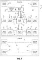
- Embodiments of braking arrangements for a vehicle 21 are shown schematically in FIGS. 1-6 .
- the vehicle 21 can be any type of vehicle, however, the present invention is believed to have particular application to vehicles such as trucks, tractors, and tractor-trailer combinations that use pneumatic brakes, such as disc brakes and/or drum brakes, for wheels on multiple axles and/or that provide anti-lock braking technology in connection with some but not all of the wheels on the vehicle's axles.
- the vehicle 21 illustrated in FIGS. 1-6 is a tractor-trailer combination comprising a tractor 23 and a trailer 25.
- Components that can be (but are not necessarily) identical in the various embodiments shown in FIGS. 1-6 are provided with the same reference numbers in the various figures. It will also be appreciated that the use of different reference numbers in the various figures does not necessarily mean that components in one figure are different from components in other figures.
- the braking arrangement includes a source of pressurized air 27 such as a reservoir or a compressor.
- the braking arrangement further comprises a first wheel 29 on a first axle A1 with a first pneumatic brake arrangement 31 including a first brake 33.
- a first brake 33 There are ordinarily two first brakes 33 (left and right) and at least two wheels 29 (left and right) on the first axle A1.
- the first brake 33 is arranged to be engaged, i.e. deliver braking torque, when connected to the source of pressurized air 27 and disengaged when disconnected from the source of pressurized air.
- the braking arrangement further comprises a second wheel 35 on a second axle A2 with a second pneumatic brake arrangement 37 including a second brake 39.
- the second brake 39 is also arranged to be engaged, i.e. deliver braking torque, when connected to the source of pressurized air 27 and disengaged when disconnected from the source of pressurized air.
- the first axle A1 will often be an auxiliary axle
- the second axle A2 will be a powered rear axle.
- the present invention is not, however, limited to such axle arrangements including an auxiliary axle and a powered rear axle, or to tandem axle vehicles.
- Additional braking arrangements may be provided for front wheels 41 and wheels 43 on other axles 45 (shown in phantom) such as axles on trailers 25.
- a proportional valve 47 is provided between the source of pressurized air 27 and the first brake 33. Opening of the proportional valve 47 and, therefore, the extent to which the first brake 33 performs a braking function, is proportional to pressure in a line 49 between the source of pressurized air 27 and a supply port 51 of the proportional valve 47.
- a proportional valve that is well-suited for use as the proportional valve 47 is a Bendix BP-R1 Bobtail Proportioning Relay Valve, available from Bendix Commercial Vehicle Systems LLC, 901 Cleveland Street, Elyria, Ohio 44035.
- a control line 53 is provided between the line 49 and a control port 55 in the proportional valve 47 so that pressure in the line 49 and, thus, the line 53, determines the extent to which the proportional valve 47 opens.
- the line 49 between the source of pressurized air 27 and the supply port 51 of the proportional valve 47 is part of a line including a line 49' between a delivery port 59 of the proportional valve and the first pneumatic brake arrangement 31.
- a conventional brake pedal arrangement 57 that includes or is associated with a valve (not shown) in the line 49 is provided and opens or closes flow from the source of pressurized air 27 to the supply port 51 of the proportional valve 47 depending upon whether the valve is depressed or not.
- the extent to which a brake pedal (not shown) of the brake pedal arrangement 57 is depressed corresponds to braking demand and determines the extent to which the valve of the brake pedal arrangement opens and, consequently, the pressure in the line 49.
- valve of the brake pedal arrangement opens more so that pressure in the line 49 increases and, as the valve of the brake pedal arrangement becomes fully open, pressure in the line 49 can approach or equal the pressure provided by the source of pressurized air 27.
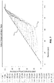
- the relationship between pressure supplied from the source of pressurized air 27 through the brake pedal arrangement 57 (i.e. the pressure arriving at the supply port 51 of the proportional valve) and pressure delivered to the first pneumatic brake arrangement 31 (i.e. the pressure delivered from a delivery port 59 of the proportional valve) will ordinarily be expected to be substantially linear, as shown by line X in FIG. 7 .
- the relationship between brake demand and brake torque applied may have a shape similar to that shown illustratively by line Y in FIG. 8 , it being understood that the line Y is merely illustrative and that different brakes may have different brake demand and brake torque curves.
- the proportional valve 47 is closed, such as by an ordinarily closed proportioning piston (not shown) that is urged to a closed position by a structure such as a spring (not shown) when the brake pedal is not depressed and pressure in the line 53 is zero.
- a structure such as a spring
- the proportional valve 47 opens as pressure in the line 53 increases and overcomes the force of the structure, such as a spring, that urges the proportioning piston to the closed position.
- the extent to which the proportional valve 47 opens depends upon the pressure in the line 49 and, thus, the line 53. By providing sufficient resistance to opening of the proportional valve 47, when there is relatively low pressure in the lines 49 and 53 the proportional valve will tend to remain mostly closed until pressure in the lines increases and the proportional valve opens more fully or completely.
- the relationship between pressure in the lines 49 and 53 and the extent to which such a proportional valve 47 opens is not linear but, rather, follows one of the curves A in FIG. 7 .
- a relay valve 61 is provided in a line 63 between the brake pedal arrangement 57 and the second pneumatic brake arrangement 37.
- the extent to which the brake pedal is depressed may be directly proportional to the pressure in the line 63 and, for purposes of discussion, will be assumed to be directly proportional to the pressure in the line 63.
- the extent to which the brake pedal is depressed will ordinarily correspond to the extent to which the second brake 39 engages, although not necessarily in a linear manner.
- the extent to which the second brake 39 engages i.e. the brake torque delivered, as the result of increased pressure in the line 63 due to depression of the brake pedal, i.e. brake demand may have more of a curved shape as shown by curve C in FIG. 8 .
- the first pneumatic brake arrangement 31 and the second pneumatic brake arrangement 37 function differently.
- the first pneumatic brake arrangement 31 and the second pneumatic brake arrangement 37 may function differently in that the first brake 33 may be a drum brake and the second brake 39 may be a disc brake as shown in FIG. 1 .
- the first pneumatic brake arrangement 31' and the second pneumatic brake arrangement 37' may function differently in that a second brake 39' including an anti-lock braking system may be associated with the second pneumatic brake arrangement and not with the first brake 33' associated with the first pneumatic brake arrangement 31'.
- first and second brakes 33' and 39' associated with the first pneumatic brake arrangement 31' and the second pneumatic brake arrangement 37' are not necessarily otherwise different.
- the first and second brakes 33' and 39' may both be drum brakes or disc brakes, however, they may be different, such as by providing drum brakes for the first brakes 33' and disc brakes for the second brakes 39'.
- the shape of a brake torque versus brake demand curve of the first pneumatic brake arrangement 31 that would ordinarily be substantially linear in the fashion of curve Y in FIG. 8 can be caused to follow a curve C that approximates the shape of the brake torque versus brake demand curve B of the second pneumatic brake arrangement 37.
- torque imbalance and uneven brake wear that tends to occur when one type of brake, such as a drum brake, is provided on one vehicle axle and a different type of brake, such as a disc brake, is provided on another can be minimized.
- the vehicle 21' shown in FIG. 4 is identical to the vehicle 21 shown in FIG. 1 except that, in the first pneumatic brake arrangement 31' in the tractor 23' of the vehicle 21', the first brakes 33' are not provided with an anti-lock braking system (ABS) while the second brakes 39' of the second pneumatic brake arrangement 37' are provided with ABS.
- ABS anti-lock braking system
- the first brakes may be the same type of brake as the second brakes (e.g., both drum brakes or both disc brakes) or may be different types of brakes (e.g., first brakes drum brakes and second brakes disc brakes).
- a line 49 extends between the source of pressurized air 27 and the supply port 51' of a proportional valve 47', and a control line 53 branches off the line 49 and leads to a control port 55' of the proportional valve.
- a line 49' extends from a delivery port 59' of the proportional valve 47' to the first pneumatic brake arrangement 31'.
- first pneumatic brake arrangement and the second pneumatic brake arrangement may function differently in other ways than in the illustrative examples expressly described herein.
- providing a proportional valve or proportional valves according to aspects of the present invention can facilitate causing the first and second pneumatic brake arrangements to behave more like each other and reduce or avoid torque imbalance and uneven brake wear and/or reduce or avoid the tendency of certain brakes to lock while others do not so that occurrence of flat spots on tires is reduced.
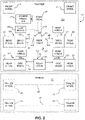
- FIGS. 2 and 5 show vehicles 121, 121', respectively, with tractors 123, 123', respectively, similar to those shown in FIGS. 1 and 4 except that, instead of a proportional valve configured to alter the curves of brake torque versus brake demand in response to pressure in a control line that corresponds the extent to which an operator depresses a brake pedal, a proportional valve 147 ( FIG. 2 ) or 147' ( FIG. 5 ) is configured to alter the curves of brake torque versus brake demand in response to the extent to which the vehicle is loaded.
- a control line 153 connects a suspension airbag 165 to a control port 155 of the proportional valve 147.
- a line 49 connects the source of pressurized air 27 to the supply port 151 of the proportional valve 147
- a line 49' connects the delivery port 159 of the proportional valve to the first pneumatic brake arrangement 131.
- the proportional valve 147 When the suspension airbag 165 is unloaded or at a minimal load such that there is no or minimal pressure in the line 153, the proportional valve 147 is closed, such as by an ordinarily closed proportioning piston (not shown) that is urged to a closed position by a structure such as a spring (not shown).
- a structure such as a spring (not shown).
- the proportional valve 147 opens as the load and pressure in the line 153 increases and overcomes the force of the structure, such as a spring, that urges the proportioning piston to the closed position.
- the extent to which the proportional valve 147 opens depends upon the pressure in the suspension airbag 165 (which is a function of the load of the vehicle on the suspension airbag) and, thus, the line 153.
- the proportional valve 147 will be less open than at higher loads and the pressure in the line 149 between the source of pressurized air 127 and the proportional valve will be less than the pressure in the line 149' between the proportional valve and the first brake 133 of the first pneumatic brake arrangement 131 so that braking torque provided is less than would otherwise be provided without the proportional valve.
- the proportional valve 147 will open to a greater extent than at lower loads and the pressure in the line 49' between the proportional valve and the first brake 133 of the first pneumatic brake arrangement 131 will approach or equal the pressure in the line 49 between the source of pressurized air 27 and the proportional valve so that braking torque provided approaches or equals that which would otherwise be provided without the proportional valve.
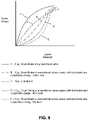
- the first brake 133 can be a brake such as a drum brake that, ordinarily (in the absence of any proportional valve), has a relationship between brake demand and brake torque that might follow a curve Y as shown in FIGS. 8 and 9
- the second brake 139 of the second pneumatic brake arrangement 137 can be a brake such as a disc brake that tends to have a relationship between brake demand and brake torque that might follow a curve such as curve C in FIGS. 8 and 9 .
- the first brake will provide less brake torque in response to a particular brake demand than it otherwise would without the proportional valve while, at the same time, the second brake 139 will provide the brake torque that it ordinarily does in response to that brake demand.
- the first brake 133 will tend to have a brake torque versus brake demand curve the same as or similar to the curve Y. As load decreases, the curve will tend to be shallower, particularly when there is low brake demand.
- the curve At high brake demand, it will ordinarily be desirable for the curve to approach the curve Y, even at low loads.
- the shallower curve of brake torque versus brake demand of the brake 133 of the first pneumatic brake arrangement 131 can more closely approximate the brake torque versus brake demand provided curve C of the second pneumatic brake arrangement 137 and torque imbalance and uneven brake wear that tends to occur when one type of brake, such as a drum brake, is provided on one vehicle axle and a different type of brake, such as a disc brake, is provided on another can be minimized.
- the vehicle 121' shown in FIG. 5 is identical to the vehicle 121 shown in FIG. 2 except that, in the first pneumatic brake arrangement 131' in the tractor 123' of the vehicle 121', the first brakes 133' are not provided with an anti-lock braking system (ABS) while the second brakes 139' of the second pneumatic brake arrangement 137' are provided with ABS.
- ABS anti-lock braking system
- the first brakes may be the same type of brake as the second brakes (e.g., both drum brakes or both disc brakes) or may be different types of brakes (e.g., first brakes drum brakes and second brakes disc brakes).
- a line 49 extends between the source of pressurized air 27 and the supply port 151' of a proportional valve 147', and a control line 153' extends from a suspension airbag 165' and leads to a control port 155' of the proportional valve.
- a line 49' extends from a delivery port 159' of the proportional valve 147' to the first pneumatic brake arrangement 131'.
- first brakes 133' are not provided with ABS will tend to reduce the tendency of those first brakes to lock and approximate the generally non-locking braking characteristics of the second brakes 139' of the second pneumatic brake arrangement 137' that are provided with ABS and will, thus, tend to reduce flat spots on tires due to locking of the first brakes.
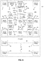
- FIGS. 3 and 6 show vehicles 221, 221', respectively, with tractors 223, 223', respectively, similar to those shown in FIGS. 1 and 4 and FIGS. 2 and 5 except that, in addition to a proportional valve 247a ( FIG. 3 ) and 247a' ( FIG. 6 ) configured to alter the curves of brake torque versus brake demand in response to pressure in a control line that corresponds the extent to which an operator depresses a brake pedal as in FIGS. 1 and 4 , a proportional valve 247b ( FIG. 3 ) or 247b' ( FIG. 6 ) is also provided in series with the proportional valves 247a and 247a' and is configured to alter the curves of brake torque versus brake demand in response to the extent to which the vehicle is loaded.
- a proportional valve 247b FIG. 3
- 247b' FIG. 6
- a control line 253a is provided between the line 49 and a control port 255a in the proportional valve 247a so that pressure in the line 49 and, thus, the line 253a, determines the extent to which the proportional valve 247a opens.
- the line 49 between the source of pressurized air 27 and the supply port 251a of the proportional valve 247a is part of a line including a line 49" between a delivery port 259a of the proportional valve 247a and a supply port 251b of the proportional valve 247b, and a line 49' between a delivery port 259b of the proportional valve 247b and the first pneumatic brake arrangement 231.
- the pressure at the delivery port 259a of the proportional valve 247a will depend upon brake demand, usually the extent to which an operator depresses a brake pedal of the brake arrangement 57.
- the first brakes 233 of the first pneumatic brake arrangement 231 can be brakes such as drum brakes that tend to have a higher brake factor than, a greater tendency to self-energize, and to dissipate heat less effectively than disc brakes, and the second brake arrangement 237 functions differently from the first brake arrangement, such as by including brakes such as disc brakes.
- a control line 253b connects a suspension airbag 265 to a control port 255b of the proportional valve 247b.
- the proportional valve 247b When there is no pressure in the suspension airbag 265 is unloaded or at a minimal load such that there is no or minimal pressure in the line 253b, the proportional valve 247b is closed or open to a minimal degree, such as by an ordinarily closed proportioning piston (not shown) that is urged to a closed position by a structure such as a spring (not shown).
- the proportional valve 247b opens as the load and pressure in the line 253 increases and overcomes the force of the structure, such as a spring, that urges the proportioning piston to the closed position.
- the extent to which the proportional valve 247b opens depends upon the pressure in the suspension airbag 265 (which is a function of the load of the vehicle on the suspension airbag) and, thus, the line 253.
- the pressure at the delivery port 259b of the proportional valve 247b will depend upon the load of the vehicle as well as upon the pressure delivered to the supply port 251b of the proportional valve 247b via the line 49" from the delivery port 259a of the proportional valve 247a, which depends upon brake demand, normally the extent to which an operator depresses the brake pedal of the brake arrangement 57. In this way, as in the illustrative graphs shown in FIG.
- the proportional valve 247b can be assumed to be fully open and the brake torque versus brake demand provided curve B of the first pneumatic brake arrangement 231 can more closely approximate the brake torque versus brake demand provided curve C of the second pneumatic brake arrangement 237 and torque imbalance and uneven brake wear that tends to occur when one type of brake, such as a drum brake, is provided on one vehicle axle and a different type of brake, such as a disc brake, is provided on another can be minimized.
- the brake torque versus brake demand curves for the first pneumatic brake arrangement are shifted so that less braking torque is provided as braking demand decreases. For example, as seen in FIG.
- the brake torque versus brake demand curve E will be shallower at low brake demand than the brake torque versus brake demand curve D when the vehicle is at 50% of maximum load, and shallower still at low brake demand than the brake torque versus brake demand curve B for the vehicle at 100% of maximum load.
- braking torque will ordinarily increase toward a maximum braking torque available through the first brake arrangement.
- the vehicle 221' shown in FIG. 6 is identical to the vehicle 221 shown in FIG. 3 except that, in the first pneumatic brake arrangement 231' in the tractor 223' of the vehicle 221', the first brakes 233' are not provided with an anti-lock braking system (ABS) while the second brakes 239' of the second pneumatic brake arrangement 237' are provided with ABS.
- ABS anti-lock braking system
- the first brakes may be the same type of brake as the second brakes (e.g., both drum brakes or both disc brakes) or may be different types of brakes (e.g., first brakes drum brakes and second brakes disc brakes).
- a line 49 extends between the source of pressurized air 27 and the supply port 251a' of a first proportional valve 247a', and a control line 253a branches off the line 49 and leads to a control port 255a' of the first proportional valve.
- a line 49" extends from a delivery port 259a' of the first proportional valve 247a' to the supply port 251b' of a second proportional valve 251b'
- a control line 253b' extends from a suspension airbag 265' to a control port 255b' of the second proportional valve
- a line 49' extends from the delivery port 259b' of the second proportional valve to the first pneumatic brake arrangement 231'.
Landscapes
- Engineering & Computer Science (AREA)
- Transportation (AREA)
- Mechanical Engineering (AREA)
- Hydraulic Control Valves For Brake Systems (AREA)
- Regulating Braking Force (AREA)
Applications Claiming Priority (1)
| Application Number | Priority Date | Filing Date | Title |
|---|---|---|---|
| US17/144,344 US11772624B2 (en) | 2021-01-08 | 2021-01-08 | Braking arrangement for a vehicle |
Publications (3)
| Publication Number | Publication Date |
|---|---|
| EP4032762A1 true EP4032762A1 (fr) | 2022-07-27 |
| EP4032762C0 EP4032762C0 (fr) | 2024-08-14 |
| EP4032762B1 EP4032762B1 (fr) | 2024-08-14 |
Family
ID=79230679
Family Applications (1)
| Application Number | Title | Priority Date | Filing Date |
|---|---|---|---|
| EP21216794.4A Active EP4032762B1 (fr) | 2021-01-08 | 2021-12-22 | Agencement de freinage pour véhicule |
Country Status (3)
| Country | Link |
|---|---|
| US (1) | US11772624B2 (fr) |
| EP (1) | EP4032762B1 (fr) |
| CN (1) | CN114750736A (fr) |
Families Citing this family (1)
| Publication number | Priority date | Publication date | Assignee | Title |
|---|---|---|---|---|
| US11938915B2 (en) * | 2021-03-17 | 2024-03-26 | Volvo Truck Corporat on | Braking arrangement for a vehicle |
Citations (2)
| Publication number | Priority date | Publication date | Assignee | Title |
|---|---|---|---|---|
| DE19940529A1 (de) * | 1999-08-26 | 2001-03-22 | Daimler Chrysler Ag | Bremsvorrichtung, insbesondere für Nutzfahrzeuge |
| WO2004020865A1 (fr) * | 2002-08-30 | 2004-03-11 | Volvo Lastvagnar Ab | Procede et appareil permettant de repartir le couple de freinage dans un vehicule a moteur |
Family Cites Families (25)
| Publication number | Priority date | Publication date | Assignee | Title |
|---|---|---|---|---|
| US3740104A (en) * | 1971-08-02 | 1973-06-19 | L Wolf | Fluid brake system with skid control |
| US3836204A (en) | 1972-07-17 | 1974-09-17 | Ford Motor Co | Brake system proportioning valve |
| US3950037A (en) | 1974-05-30 | 1976-04-13 | Ford Motor Company | Brake proportioning valve for a motor vehicle responsive to both the rate of vehicle deceleration and vehicle load variation |
| US4453778A (en) | 1980-01-10 | 1984-06-12 | Ford Motor Company | Proportioning hydraulic brake mechanism |
| DE3106640A1 (de) * | 1981-02-23 | 1982-09-09 | Wabco Fahrzeugbremsen Gmbh, 3000 Hannover | Druckluftbremsanlage fuer luftgefederte drei- und mehrachs-strassenfahrzeuge |
| CA1262753A (fr) | 1984-05-09 | 1989-11-07 | Tsutomu Hayashi | Mecanisme anticalage des freins de vehicules |
| US4836616A (en) | 1986-01-31 | 1989-06-06 | Rockwell International Corporation | Antilock brake system |
| DE3838571A1 (de) | 1988-11-14 | 1990-05-17 | Lucas Ind Plc | Blockiergeschuetzte bremsanlage |
| JP2628807B2 (ja) | 1991-07-30 | 1997-07-09 | 住友電気工業株式会社 | アンチロック制御装置 |
| DE19814867C1 (de) | 1998-04-02 | 1999-12-23 | Knorr Bremse Systeme | Verfahren und Vorrichtung zur Bremskraftaufteilung auf die Achsen eines mit einer Blockierschutzeinrichtung ausgestatteten Kraftfahrzeuges |
| US6746031B2 (en) * | 2001-10-15 | 2004-06-08 | Meritor Light Vehicle Technology, Llc | Suspension structure as accumulator for vehicle air systems |
| CN201520291U (zh) | 2009-07-20 | 2010-07-07 | 杨继新 | 一种汽车制动系安全装置 |
| CN201677874U (zh) | 2010-01-29 | 2010-12-22 | 江苏九龙汽车制造有限公司 | 一种汽车制动系统 |
| CN102139689A (zh) | 2010-01-29 | 2011-08-03 | 江苏九龙汽车制造有限公司 | 一种汽车制动系统 |
| CN202368566U (zh) * | 2011-11-18 | 2012-08-08 | 北汽福田汽车股份有限公司 | 气压式制动车辆及其车辆制动控制装置 |
| JP6000663B2 (ja) * | 2012-06-04 | 2016-10-05 | 日野自動車株式会社 | 自動制動制御装置 |
| JP2015039953A (ja) | 2013-08-21 | 2015-03-02 | ダイハツ工業株式会社 | 車両用制動装置 |
| US9387846B2 (en) | 2014-02-28 | 2016-07-12 | Tramec Sloan, Llc | Modulator valve |
| CN106143457A (zh) * | 2015-04-09 | 2016-11-23 | 天津纳尚科技发展有限公司 | 一种汽车制动真空助力器系统 |
| DE102015011296A1 (de) | 2015-09-02 | 2017-03-02 | Wabco Gmbh | Elektronisch steuerbares pneumatisches Bremssystem in einem Nutzfahrzeug sowie Verfahren zum elektronischen Steuern eines pneumatischen Bremssystems |
| US10300902B2 (en) | 2017-06-21 | 2019-05-28 | Gm Global Technology Operations Llc. | Method and apparatus for monitoring a vehicle braking system |
| WO2019036276A1 (fr) * | 2017-08-14 | 2019-02-21 | Hendrickson Usa, L.L.C. | Système de frein pneumatique |
| EP3511214A1 (fr) | 2018-01-10 | 2019-07-17 | WABCO Europe BVBA | Système de frein à air avec soupape de détection de charge |
| WO2019210952A1 (fr) * | 2018-05-03 | 2019-11-07 | Volvo Truck Corporation | Système de freinage redondant de poids lourd utilitaire |
| CN111267809B (zh) * | 2020-03-04 | 2021-05-14 | 中国矿业大学 | 一种重型运输车分布式液-气制动系统及控制方法 |
-
2021
- 2021-01-08 US US17/144,344 patent/US11772624B2/en active Active
- 2021-12-07 CN CN202111485704.9A patent/CN114750736A/zh active Pending
- 2021-12-22 EP EP21216794.4A patent/EP4032762B1/fr active Active
Patent Citations (2)
| Publication number | Priority date | Publication date | Assignee | Title |
|---|---|---|---|---|
| DE19940529A1 (de) * | 1999-08-26 | 2001-03-22 | Daimler Chrysler Ag | Bremsvorrichtung, insbesondere für Nutzfahrzeuge |
| WO2004020865A1 (fr) * | 2002-08-30 | 2004-03-11 | Volvo Lastvagnar Ab | Procede et appareil permettant de repartir le couple de freinage dans un vehicule a moteur |
Also Published As
| Publication number | Publication date |
|---|---|
| US11772624B2 (en) | 2023-10-03 |
| EP4032762C0 (fr) | 2024-08-14 |
| US20220219662A1 (en) | 2022-07-14 |
| EP4032762B1 (fr) | 2024-08-14 |
| CN114750736A (zh) | 2022-07-15 |
Similar Documents
| Publication | Publication Date | Title |
|---|---|---|
| US11247649B2 (en) | Method for decelerating a vehicle combination and combination of pneumatic brake systems of the vehicles of a vehicle combination | |
| US5163742A (en) | Method of distributing brake pressure to the axles of a motor vehicle with an abs pressure-medium brake | |
| US6804598B2 (en) | System and method for controlling brake actuation energy in electronically-controlled vehicle brake systems | |
| US11091134B2 (en) | Method for brake control of a vehicle combination, and vehicle combination for use therewith | |
| JP3116314B2 (ja) | 昇降可能な後続車軸を持つ車両 | |
| CN107750214B (zh) | 用于电子调节车辆的压力介质操控式制动设备中的制动力分配的方法以及车辆的具有这种调节的压力介质操控式制动设备 | |
| US5957552A (en) | Vehicle with brake force regulations on gradient | |
| JPS6160357A (ja) | 車輌ブレーキ装置並びにその運転法 | |
| JPS62122856A (ja) | 鳴き防止機能を有する車両用ブレ−キシステム | |
| US11059467B2 (en) | Braking force control apparatus for vehicle | |
| US3918767A (en) | Antiskid vehicle brake system for individual wheel control including a fluid pressure comparator device | |
| US4768843A (en) | Vehicle brake control system | |
| EP4032762B1 (fr) | Agencement de freinage pour véhicule | |
| US20240198981A1 (en) | Method for operating a vehicle combination | |
| EP3969337A1 (fr) | Système de freinage de véhicule doté d'une fonction de gestion de composé | |
| US6375281B1 (en) | Brake torque regulation for vehicles | |
| JPS6227483Y2 (fr) | ||
| US3297368A (en) | Load controlled brake proportioning system | |
| JPH10278763A (ja) | 車両を制動する方法 | |
| CS264114B2 (en) | Vehicle with a braking pressure reducing valve working in dependence on load | |
| GB2138086A (en) | Brake force distribution in motor vehicles | |
| JPH11505788A (ja) | 車両用ブレーキシステム | |
| US3376079A (en) | Load responsive braking system | |
| WO2008110797A1 (fr) | Systèmes de freinage de remorque | |
| GB2080899A (en) | Load responsive valve for regulating pressure in vehicle dual- circuit pneumatic brake system |
Legal Events
| Date | Code | Title | Description |
|---|---|---|---|
| PUAI | Public reference made under article 153(3) epc to a published international application that has entered the european phase |
Free format text: ORIGINAL CODE: 0009012 |
|
| STAA | Information on the status of an ep patent application or granted ep patent |
Free format text: STATUS: THE APPLICATION HAS BEEN PUBLISHED |
|
| AK | Designated contracting states |
Kind code of ref document: A1 Designated state(s): AL AT BE BG CH CY CZ DE DK EE ES FI FR GB GR HR HU IE IS IT LI LT LU LV MC MK MT NL NO PL PT RO RS SE SI SK SM TR |
|
| STAA | Information on the status of an ep patent application or granted ep patent |
Free format text: STATUS: REQUEST FOR EXAMINATION WAS MADE |
|
| 17P | Request for examination filed |
Effective date: 20230118 |
|
| RBV | Designated contracting states (corrected) |
Designated state(s): AL AT BE BG CH CY CZ DE DK EE ES FI FR GB GR HR HU IE IS IT LI LT LU LV MC MK MT NL NO PL PT RO RS SE SI SK SM TR |
|
| GRAP | Despatch of communication of intention to grant a patent |
Free format text: ORIGINAL CODE: EPIDOSNIGR1 |
|
| STAA | Information on the status of an ep patent application or granted ep patent |
Free format text: STATUS: GRANT OF PATENT IS INTENDED |
|
| INTG | Intention to grant announced |
Effective date: 20240319 |
|
| GRAS | Grant fee paid |
Free format text: ORIGINAL CODE: EPIDOSNIGR3 |
|
| GRAA | (expected) grant |
Free format text: ORIGINAL CODE: 0009210 |
|
| STAA | Information on the status of an ep patent application or granted ep patent |
Free format text: STATUS: THE PATENT HAS BEEN GRANTED |
|
| AK | Designated contracting states |
Kind code of ref document: B1 Designated state(s): AL AT BE BG CH CY CZ DE DK EE ES FI FR GB GR HR HU IE IS IT LI LT LU LV MC MK MT NL NO PL PT RO RS SE SI SK SM TR |
|
| REG | Reference to a national code |
Ref country code: GB Ref legal event code: FG4D |
|
| REG | Reference to a national code |
Ref country code: CH Ref legal event code: EP |
|
| REG | Reference to a national code |
Ref country code: DE Ref legal event code: R096 Ref document number: 602021017160 Country of ref document: DE |
|
| REG | Reference to a national code |
Ref country code: IE Ref legal event code: FG4D |
|
| U01 | Request for unitary effect filed |
Effective date: 20240912 |
|
| U07 | Unitary effect registered |
Designated state(s): AT BE BG DE DK EE FI FR IT LT LU LV MT NL PT RO SE SI Effective date: 20240917 |
|
| PG25 | Lapsed in a contracting state [announced via postgrant information from national office to epo] |
Ref country code: NO Free format text: LAPSE BECAUSE OF FAILURE TO SUBMIT A TRANSLATION OF THE DESCRIPTION OR TO PAY THE FEE WITHIN THE PRESCRIBED TIME-LIMIT Effective date: 20241114 |
|
| PG25 | Lapsed in a contracting state [announced via postgrant information from national office to epo] |
Ref country code: PL Free format text: LAPSE BECAUSE OF FAILURE TO SUBMIT A TRANSLATION OF THE DESCRIPTION OR TO PAY THE FEE WITHIN THE PRESCRIBED TIME-LIMIT Effective date: 20240814 Ref country code: GR Free format text: LAPSE BECAUSE OF FAILURE TO SUBMIT A TRANSLATION OF THE DESCRIPTION OR TO PAY THE FEE WITHIN THE PRESCRIBED TIME-LIMIT Effective date: 20241115 |
|
| PG25 | Lapsed in a contracting state [announced via postgrant information from national office to epo] |
Ref country code: IS Free format text: LAPSE BECAUSE OF FAILURE TO SUBMIT A TRANSLATION OF THE DESCRIPTION OR TO PAY THE FEE WITHIN THE PRESCRIBED TIME-LIMIT Effective date: 20241214 |
|
| PG25 | Lapsed in a contracting state [announced via postgrant information from national office to epo] |
Ref country code: HR Free format text: LAPSE BECAUSE OF FAILURE TO SUBMIT A TRANSLATION OF THE DESCRIPTION OR TO PAY THE FEE WITHIN THE PRESCRIBED TIME-LIMIT Effective date: 20240814 |
|
| PG25 | Lapsed in a contracting state [announced via postgrant information from national office to epo] |
Ref country code: RS Free format text: LAPSE BECAUSE OF FAILURE TO SUBMIT A TRANSLATION OF THE DESCRIPTION OR TO PAY THE FEE WITHIN THE PRESCRIBED TIME-LIMIT Effective date: 20241114 Ref country code: ES Free format text: LAPSE BECAUSE OF FAILURE TO SUBMIT A TRANSLATION OF THE DESCRIPTION OR TO PAY THE FEE WITHIN THE PRESCRIBED TIME-LIMIT Effective date: 20240814 |
|
| U20 | Renewal fee for the european patent with unitary effect paid |
Year of fee payment: 4 Effective date: 20241225 |
|
| PG25 | Lapsed in a contracting state [announced via postgrant information from national office to epo] |
Ref country code: RS Free format text: LAPSE BECAUSE OF FAILURE TO SUBMIT A TRANSLATION OF THE DESCRIPTION OR TO PAY THE FEE WITHIN THE PRESCRIBED TIME-LIMIT Effective date: 20241114 Ref country code: PL Free format text: LAPSE BECAUSE OF FAILURE TO SUBMIT A TRANSLATION OF THE DESCRIPTION OR TO PAY THE FEE WITHIN THE PRESCRIBED TIME-LIMIT Effective date: 20240814 Ref country code: NO Free format text: LAPSE BECAUSE OF FAILURE TO SUBMIT A TRANSLATION OF THE DESCRIPTION OR TO PAY THE FEE WITHIN THE PRESCRIBED TIME-LIMIT Effective date: 20241114 Ref country code: IS Free format text: LAPSE BECAUSE OF FAILURE TO SUBMIT A TRANSLATION OF THE DESCRIPTION OR TO PAY THE FEE WITHIN THE PRESCRIBED TIME-LIMIT Effective date: 20241214 Ref country code: HR Free format text: LAPSE BECAUSE OF FAILURE TO SUBMIT A TRANSLATION OF THE DESCRIPTION OR TO PAY THE FEE WITHIN THE PRESCRIBED TIME-LIMIT Effective date: 20240814 Ref country code: GR Free format text: LAPSE BECAUSE OF FAILURE TO SUBMIT A TRANSLATION OF THE DESCRIPTION OR TO PAY THE FEE WITHIN THE PRESCRIBED TIME-LIMIT Effective date: 20241115 Ref country code: ES Free format text: LAPSE BECAUSE OF FAILURE TO SUBMIT A TRANSLATION OF THE DESCRIPTION OR TO PAY THE FEE WITHIN THE PRESCRIBED TIME-LIMIT Effective date: 20240814 |
|
| PG25 | Lapsed in a contracting state [announced via postgrant information from national office to epo] |
Ref country code: SM Free format text: LAPSE BECAUSE OF FAILURE TO SUBMIT A TRANSLATION OF THE DESCRIPTION OR TO PAY THE FEE WITHIN THE PRESCRIBED TIME-LIMIT Effective date: 20240814 |
|
| PG25 | Lapsed in a contracting state [announced via postgrant information from national office to epo] |
Ref country code: CZ Free format text: LAPSE BECAUSE OF FAILURE TO SUBMIT A TRANSLATION OF THE DESCRIPTION OR TO PAY THE FEE WITHIN THE PRESCRIBED TIME-LIMIT Effective date: 20240814 |
|
| PG25 | Lapsed in a contracting state [announced via postgrant information from national office to epo] |
Ref country code: SK Free format text: LAPSE BECAUSE OF FAILURE TO SUBMIT A TRANSLATION OF THE DESCRIPTION OR TO PAY THE FEE WITHIN THE PRESCRIBED TIME-LIMIT Effective date: 20240814 |
|
| PLBI | Opposition filed |
Free format text: ORIGINAL CODE: 0009260 |
|
| PLAX | Notice of opposition and request to file observation + time limit sent |
Free format text: ORIGINAL CODE: EPIDOSNOBS2 |
|
| 26 | Opposition filed |
Opponent name: ZF CV SYSTEMS EUROPE BV Effective date: 20250514 |
|
| PG25 | Lapsed in a contracting state [announced via postgrant information from national office to epo] |
Ref country code: MC Free format text: LAPSE BECAUSE OF FAILURE TO SUBMIT A TRANSLATION OF THE DESCRIPTION OR TO PAY THE FEE WITHIN THE PRESCRIBED TIME-LIMIT Effective date: 20240814 |
|
| REG | Reference to a national code |
Ref country code: CH Ref legal event code: PL |
|
| PLBB | Reply of patent proprietor to notice(s) of opposition received |
Free format text: ORIGINAL CODE: EPIDOSNOBS3 |
|
| PG25 | Lapsed in a contracting state [announced via postgrant information from national office to epo] |
Ref country code: CH Free format text: LAPSE BECAUSE OF NON-PAYMENT OF DUE FEES Effective date: 20241231 |
|
| PG25 | Lapsed in a contracting state [announced via postgrant information from national office to epo] |
Ref country code: IE Free format text: LAPSE BECAUSE OF NON-PAYMENT OF DUE FEES Effective date: 20241222 |
|
| U20 | Renewal fee for the european patent with unitary effect paid |
Year of fee payment: 5 Effective date: 20251223 |