EP4032763B1 - Un système de freinage pour freiner un véhicule - Google Patents
Un système de freinage pour freiner un véhicule Download PDFInfo
- Publication number
- EP4032763B1 EP4032763B1 EP21153227.0A EP21153227A EP4032763B1 EP 4032763 B1 EP4032763 B1 EP 4032763B1 EP 21153227 A EP21153227 A EP 21153227A EP 4032763 B1 EP4032763 B1 EP 4032763B1
- Authority
- EP
- European Patent Office
- Prior art keywords
- brake
- signal
- actuator
- circuit
- switching
- Prior art date
- Legal status (The legal status is an assumption and is not a legal conclusion. Google has not performed a legal analysis and makes no representation as to the accuracy of the status listed.)
- Active
Links
Images

Classifications
-
- B—PERFORMING OPERATIONS; TRANSPORTING
- B60—VEHICLES IN GENERAL
- B60T—VEHICLE BRAKE CONTROL SYSTEMS OR PARTS THEREOF; BRAKE CONTROL SYSTEMS OR PARTS THEREOF, IN GENERAL; ARRANGEMENT OF BRAKING ELEMENTS ON VEHICLES IN GENERAL; PORTABLE DEVICES FOR PREVENTING UNWANTED MOVEMENT OF VEHICLES; VEHICLE MODIFICATIONS TO FACILITATE COOLING OF BRAKES
- B60T17/00—Component parts, details, or accessories of power brake systems not covered by groups B60T8/00, B60T13/00 or B60T15/00, or presenting other characteristic features
- B60T17/18—Safety devices; Monitoring
- B60T17/22—Devices for monitoring or checking brake systems; Signal devices
- B60T17/221—Procedure or apparatus for checking or keeping in a correct functioning condition of brake systems
-
- B—PERFORMING OPERATIONS; TRANSPORTING
- B60—VEHICLES IN GENERAL
- B60T—VEHICLE BRAKE CONTROL SYSTEMS OR PARTS THEREOF; BRAKE CONTROL SYSTEMS OR PARTS THEREOF, IN GENERAL; ARRANGEMENT OF BRAKING ELEMENTS ON VEHICLES IN GENERAL; PORTABLE DEVICES FOR PREVENTING UNWANTED MOVEMENT OF VEHICLES; VEHICLE MODIFICATIONS TO FACILITATE COOLING OF BRAKES
- B60T13/00—Transmitting braking action from initiating means to ultimate brake actuator with power assistance or drive; Brake systems incorporating such transmitting means, e.g. air-pressure brake systems
- B60T13/74—Transmitting braking action from initiating means to ultimate brake actuator with power assistance or drive; Brake systems incorporating such transmitting means, e.g. air-pressure brake systems with electrical assistance or drive
- B60T13/741—Transmitting braking action from initiating means to ultimate brake actuator with power assistance or drive; Brake systems incorporating such transmitting means, e.g. air-pressure brake systems with electrical assistance or drive acting on an ultimate actuator
Definitions
- the present invention relates to a brake system for braking a vehicle, and an automotive actuator, e.g. for braking a wheel as part of the brake system.
- ASIL Automotive Safety Integrity Level
- ISO 26262 Functional Safety for Road Vehicles standard. This is an adaptation of the Safety Integrity Level (SIL) used in IEC 61508 for the automotive industry. This classification helps defining the safety requirements necessary to be in line with the ISO 26262 standard.
- the ASIL is established by performing a risk analysis of a potential hazard by looking at the Severity, Exposure and Controllability of the vehicle operating scenario. The safety goal for that hazard in turn carries the ASIL requirements.
- ASIL D dictates the highest integrity requirements on the product and ASIL A the lowest.
- Hazards that are identified as "Quality Management" (QM) do not dictate any safety requirements.
- QM Quality Management
- the required ASIL classification of components can be lowered through a technique referred to as ASIL Decomposition.
- a safety function implemented in an integrated device having high ASIL rating may be decomposed into independent sub-functions or components, with possibly lower ASIL. This can be advantageous, for example, with respect to improving system robustness and/or lowering production costs. However, it can be difficult to assure independent operation of the decomposed elements.
- the Smart Brake Fail Operational Decomposed Actuator safety concept can achieve ASIL D requirements on system level with the use of lower complexity (ASIL B) E/E hardware components.
- the Smart Brake Fail Operational Decomposed Actuator concept has two channels which both can be comprised of an ASIL B level control unit and inverter.
- each brake actuator controller comprises a main brake circuit configured to provide the power signal based on a first actuator control signal received from the central controller. Furthermore each brake actuator controller comprises a backup brake circuit configured to independently provide the power signal, in case the main brake circuit fails, based on a second actuator control signal received from the central controller.
- each brake actuator controller comprises a switching circuit. The switching circuit is configured to exclusively relay the power signal received from either the main brake circuit or the backup brake circuit to the brake actuation mechanism based on a switching signal received from the central controller independently of the actuator control signals.
- the central controller can be classified as ASIL-D to reliably decide whether to switch between the main and backup circuits in the respective brake actuator controller, so the required classification of these independent circuits can be lower, e.g. ASIL-B.
- the brake system preferably comprises an automotive actuator for applying a force or torque in an automotive component, in particular a brake actuator for braking a wheel.
- the actuator comprises an actuation mechanism.
- the actuation mechanism comprises a clamping device or other actuated device for applying an amount of braking to the wheel, e.g. by clamping a brake disc connected to the wheel.
- the actuation mechanism comprises or couples to an electric motor operably connected to the actuated device via a transmission.
- the automotive actuator further comprises an actuator controller, e.g. the brake actuator controller as described earlier.
- the actuator controller comprises a main circuit configured to provide a power signal to the electric motor based on a first actuator control signal received from a central controller via a main network port.
- the actuator controller comprises a backup circuit configured to independently provide the power signal, in case the main circuit fails, based on a second actuator control signal received from the central controller via a backup network port. Furthermore, the actuator controller comprises a switching circuit configured to exclusively relay the power signal received from either the main circuit or the backup circuit to the actuation mechanism based on a switching signal received independently of the actuator control signals via a signal port separate from the main and backup network ports.
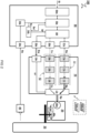
- FIG 1 illustrates a vehicle 1000 with a brake system 100 for braking a vehicle 1000.
- the brake system comprises a respective brake actuator controller 10 for one or more wheels 30 of the vehicle 1000, preferably each wheel 30.
- the brake actuator controller 10 is configured to apply a respective power signal "Sp" to power a respective brake actuation mechanism 20 for applying an amount of braking BR to the wheel 30. For example, this can be based at least on a respective actuator control signal "Sa" received by the brake actuator controller 10.
- the brake system comprises a central controller 50.
- the central controller 50 is configured to control the braking of the vehicle by sending the respective actuator control signal "Sa" to the respective brake actuator controller 10 of each wheel 30. For example, this can be based on a brake intent signal "Si" received by the central controller 50.
- each brake actuator controller 10 comprises at least a main brake circuit 11 and a backup brake circuit 12.
- the main brake circuit 11 is configured to provide the power signal "Sp" based on a first actuator control signal "Sa", e.g. received from the central controller 50.
- the backup brake circuit 12 is configured to (independently) provide the power signal "Sp", e.g. in case the main brake circuit 11 fails, based on a second actuator control signal "Sa” which can also be received from the central controller 50.
- the brake actuator controller 10 comprises a switching circuit 13 configured to exclusively relay the power signal "Sp" received from either the main brake circuit 11 or the backup brake circuit 12 to the brake actuation mechanism 20. Most preferably, this based on a switching signal "Sw” received independently of the actuator control signals Sa. For example, the switching signal "Sw" is also received from the central controller 50.
- the main brake circuit 11 is configured to provide a power signal "Sp" to the brake motor 10m based on a first actuator control signal "Sa” received from a central controller 50 via a main network port 51p.
- the backup brake circuit 12 is configured to independently provide the power signal "Sp", in case the main brake circuit 11 fails, based on a second actuator control signal "Sa" received from the central controller 50 via a backup network port 52p.
- the switching circuit 13 is configured to exclusively relay the power signal "Sp" received from either the main brake circuit 11 or the backup brake circuit 12 to the brake actuation mechanism 20 based on a switching signal "Sw” received independently of the actuator control signals Sa via a signal port 13p separate from the main and backup network ports 51p,52p.
- An electric brake for a vehicle typically has an electromechanical actuation mechanism, configured to press a friction brake lining for braking against a brake body that is mounted to a vehicle wheel.
- the brake body, or rotor is typically a brake disc or a brake drum.
- the actuation device typically has an electric motor and a rotation-to-translation conversion gear that converts a rotary driving motion of the electric motor into a translational motion for pressing the friction brake lining against the brake body.
- Worm gears such as spindle gears or roller worm drives, are often used as rotation-to-translation conversion gears. It is also possible to convert the rotary motion into a translational motion by means of a pivotable cam, for instance.
- a step-down gear for instance in the form of a planetary gear, is often placed between the electric motor and the rotation-to-translation conversion gear.
- Self-boosting electromechanical vehicle brakes have a self-booster that converts a frictional force, exerted by the rotating brake body against the friction brake lining that is pressed for braking against the brake body, into a contact pressure, which presses the friction brake lining against the brake body in addition to a contact pressure that is exerted by the actuation device.
- Wedge, ramp, and lever mechanisms are suitable for the self-boosting.
- the brake intent signal "Si" is generated based on user interaction with a service and/or parking brake 60, and/or generated autonomously by a vehicle motion control system (not shown).
- the brake intent signal "Si” is received directly or indirectly from the service and/or parking brake 60.
- the brake intent signal "Si” is generated when a brake pedal is operated.
- the brake intent signal "Si” is generated autonomously by a motion controller of the vehicle.
- the vehicle comprises a sensor system configured to detect impending danger and activate the brake system accordingly. So it will be understood that the brake system can also be operated as part of a partially or fully self-driving vehicle.
- the central controller 50 is configured to receive a sensor signal "Ss" from a motion sensor 40 measuring a motion of the vehicle and/or wheel 30. In one embodiment, the central controller 50 is configured to send the switching signal "Sw" to the switching circuit 13 for relaying the power signal "Sp" of the backup brake circuit 12 instead of the main brake circuit 11, or vice versa, based on the sensor signal "Ss".
- the central controller 50 is configured to send the switching signal "Sw" to one or more brake actuator controllers 10 for switching the switching circuit 13, if the central controller 50 determines, based on the sensor signal "Ss", that the measured motion of the vehicle and/or wheel 30 deviates from an expected motion corresponding to the actuator control signal "Sa” and/or brake intent signal "Si".
- the motion sensor 40 comprises a wheel speed sensor configured to individually measure the wheel speed of each wheel of the vehicle.
- the central controller 50 is configured to receive a respective wheel speed signal from each wheel 30.
- the central controller 50 is configured to send the switching signal "Sw" for switching to the backup brake circuit 12 exclusively to the respective brake actuator controller 10 of the specific wheel.
- the switching signal "Sw” is sent if it is determined that a measured wheel speed of a specific wheel deviates from an expected wheel speed corresponding to the actuator control signal "Sa" (that was sent to the respective brake actuator controller 10 of the specific wheel 30). In this way, only the faulty brake actuator controllers 10 of a specific wheel may need to be switched to its backup circuit, while the controllers of the other wheels can remain to use their main circuit.
- the motion sensor 40 comprises an inertial sensor configured to measure acceleration and/or deceleration of the vehicle.
- the central controller 50 is configured to receive an acceleration and/or deceleration signal from the inertial sensor and send the switching signal "Sw" for switching each of the brake actuator controller 10 from the main brake circuit 11 to the backup brake circuit 12, or vice versa.
- the problem may be immediately remedied by switching each of the brake actuator controller 10 to an alternate brake circuit 11. For example, this can alleviate braking problems even if it cannot be directly determined which specific controller has failed.
- the central controller 50 is configured to periodically test the backup brake circuit 12 by switching the brake actuator controller 10 to use the backup brake circuit 12 instead of main brake circuit 11 absent any detected failure in the brake system 100.
- the central controller 50 is configured to periodically test the backup brake circuit 12 when the vehicle is parked by applying a parking brake using the backup brake circuit 12 and monitor subsequent motion of the vehicle and/or wheels. For example, when the vehicle or wheel starts moving after the brake is actuated using the backup brake circuit 12, this is an indication there is a fault in the backup brake circuit 12. By testing this during parking there is relatively low risk associated with the test.
- FIG 2 illustrates further details of a preferred components in a brake system 100.
- the central controller 50 is configured to communicate with each brake actuator controller 10 using a set of at least two separate parallel cables between the central controller 50 and respective brake actuator controller 10. For example, a first cable is configured to send the actuator control signal "Sa" to the main brake circuit 11 and a second cable is configured to send the actuator control signal "Sa" to the backup brake circuit 12.
- the central controller 50 is configured to send the actuator control signal "Sa” using two or more network cables arranged in parallel between the central controller 50 and brake actuator controller 10.
- the actuator control signal "Sa” is communicated using a message based protocol such as CAN or Ethernet. Such protocol can provide flexibility in communicating various types of information.
- the central controller 50 is configured to communicate the switching signal "Sw" to each brake actuator controller 10 using at least one additional cable, e.g. separate from the set of at cables used for communicating the actuator control signal "Sa".
- the actuator control signal "Sw” is communicated by applying a fixed voltage on a respective signal line.
- the switching signal "Sw” can be simply communicated by switching between a high and low voltage, e.g. 5v and 0V, or any other voltage. Such way of communication can be relatively simple and robust so the chance of failure can be minimized.
- the central controller 50 is configured to communicate the switching signal "Sw" to each brake actuator controller 10 using two signal lines.
- the brake actuator controller 10 is configured to determine the switching signal "Sw" based on a combination of voltages received from the two signal lines. For example, in normal operation, an "on" or “high” voltage signal (1) is continuously provided on each of the signal lines. When both of the signals is switched to an "off' or “low” voltage (0) this can be used as an indication to operate the switching circuit 13. This redundancy may prevent inadvertent switching when one of the signal lines is broken. Of course also other combinations of signals can be used. By switching the switching circuit 13 using a limited number of signals, e.g. one or two bits, the chance of failure for such switching can be lowered. In principle also more than two, e.g. three, signal lines can be used for further redundancy.
- each brake circuit 11,12 comprises a separate set of components.
- the set of components includes a network port 11p, 12p configured to receive a respective actuator control signal "Sa".
- the set of components includes an inverter 11i, 12i configured to generate a respective power signal "Sp”.
- the set of components includes a brake actuator processor 11c, 12c configured to control the main brake circuit 11 to generate the power signal "Sp" based on the actuator control signal "Sa”.
- (the components of) the respective brake circuits 11,12 are classified as ASIL-B or ASIL-C.
- the brake actuator processor 11c, 12c can be a relatively simple processor, e.g. single core as opposed to a dual-core lockstep processor which is typically needed for being rated as ASIL-D.
- the switching circuit 13 comprises a signal port 13p configured to receive the switching signal "Sw", e.g. one or more voltages.
- the switching circuit 13 comprises a switching relay 13r controlled by the switching signal "Sw" to form an electrical connection between an output of a respective inverter 11i, 12i of either the main brake circuit 11 or the backup brake circuit 12.
- at least the components of the switching circuit 13 are classified as ASIL-D.
- the ASIL-D classification of the switching circuit 13 can be used to apply reliable ASIL decomposition of components in the brake actuator controller 10 by improved separation between the operation of the main and backup brake circuits, which can thus be of lower classification ASIL-B without compromising safety.
- the central controller 50 comprises at least one signal port 54s for receiving a sensor signal "Ss" from a motion sensor 40 measuring a motion of the vehicle and/or wheel 30.
- the central controller 50 comprises a sensor signal acquisition unit 54a configured to generate a conditioned sensor signal "Sc" based on the sensor signal "Ss" received from the signal port 54s.
- the central controller 50 comprises a black-box actuator safety unit 54b configured to generate a safety mechanism result Sf based on the conditioned sensor signal "Sc".
- the safety mechanism result Sf can also be based on an indication Sa' of the actuator control signal "Sa", e.g.
- the central controller 50 comprises an actuator control safety unit 50f.
- the actuator control safety unit 50f is configured to generate the switching signal "Sw” based on the safety mechanism result Sf, and/or to selectively output the actuator control signal "Sa" to one of a main network port 51p and a backup network port 52p based on the safety mechanism result Sf.
- these ports 51p,52p are connected to the respective network ports 11p,12p of the main and backup brake circuits 11,12.
- the central controller 50 comprises a brake system control module 50m configured to determine an individual brake intent for each wheel 30 based on the received brake intent signal "Si".
- the brake system control module 50m may also include other considerations, e.g. other sensor inputs.
- the brake system control module 50m may implement an anti-lock braking system (ABS), electronic stability control (ESC), or other traction control.
- the central controller 50 comprises an actuator control module 50a configured to individually generate a respective actuator control signal "Sa" for each wheel based on the individual brake intent signal.
- the actuator control module 50a is configured to generate the generate a respective actuator control signal "Sa" for each wheel further based on a (conditioned) sensor signal "Sc" indicating a motion of the wheel.
- the central controller 50 is classified as ASIL-D.
- the central controller 50 comprises a dual core lockstep processor.
- the units and modules as described herein with reference to the central controller 50 can be implemented in hardware and/or software components. While the functions are depicted as separate blocks, these blocks or functions can also be integrated, further subdivided, or omitted (e.g. because their respective function is not strictly necessary).
- the functions of the brake system control module 50m and the actuator control module 50a can be combined.
- the functions of the black-box actuator safety unit 54b can be integrated in the actuator control safety unit 50f and can also be made part of the brake system control module 50a.
- the sensor signal acquisition unit 54a may be omitted and the sensor signal "Ss" directly input into the black-box actuator safety unit 54b and/or actuator control safety unit 50f.
- the present teachings are especially beneficial in the control of a brake system, in principle the present teachings can also be applied to other automotive components that benefit from reliable control, in particular allowing the use of cost-effective redundant circuits while maintaining the highest vehicle safety requirements.
Landscapes
- Engineering & Computer Science (AREA)
- Transportation (AREA)
- Mechanical Engineering (AREA)
- Valves And Accessory Devices For Braking Systems (AREA)
- Regulating Braking Force (AREA)
Claims (15)
- Système de freinage (100) pour freiner un véhicule (1000), le système de freinage comprenantpour au moins une, de préférence chaque roue (30) du véhicule, un contrôleur d'actionneur de frein respectif (10) configuré pour appliquer un signal de puissance respectif (Sp) pour alimenter un mécanisme d'actionnement de frein respectif (20) pour appliquer une quantité de freinage (BR) à la roue (30) sur la base au moins d'un signal de commande d'actionneur respectif (Sa) reçu par le contrôleur d'actionneur de frein (10);un contrôleur central (50) configuré pour contrôler le freinage du véhicule en envoyant le signal de contrôle d'actionneur respectif (Sa) à chaque contrôleur d'actionneur de frein respectif (10) sur la base d'un signal d'intention de freinage (Si) reçu par le contrôleur central (50);dans lequel chaque contrôleur d'actionneur de frein (10) comprendun circuit de frein principal (11) configuré pour fournir le signal de puissance (Sp) sur la base d'un premier signal de commande d'actionneur (Sa) reçu du contrôleur central (50),un circuit de freinage de secours (12) configuré pour fournir le signal de puissance (Sp), en cas de panne du circuit de freinage principal (11), etun circuit de commutation (13) configuré pour relayer exclusivement le signal de puissance (Sp) reçu soit du circuit de frein principal (11) soit du circuit de frein de secours (12) au mécanisme d'actionnement de frein (20)caractérisé en ce quele circuit de freinage de secours (12) est configuré pour fournir indépendamment le signal de puissance (Sp), sur la base d'un deuxième signal de commande d'actionneur (Sa) reçu du contrôleur central (50), etle circuit de commutation (13) est configuré pour relayer le signal de puissance (Sp) sur la base d'un signal de commutation (Sw) reçu indépendamment des signaux de commande d'actionneur (Sa).
- Système de freinage selon la revendication précédente, dans lequel le contrôleur central (50) est configuré pour recevoir un signal de capteur (Ss) d'un capteur de mouvement (40) mesurant un mouvement du véhicule et/ou de la roue (30), dans lequel le contrôleur central (50) est configuré pour envoyer le signal de commutation (Sw) au circuit de commutation (13) pour relayer le signal de puissance (Sp) du circuit de freinage de secours (12) à la place du circuit de freinage principal (11), ou vice versa, sur la base du signal de capteur (Ss).
- Système de freinage selon la revendication précédente, dans lequel le contrôleur central (50) est configuré pour envoyer le signal de commutation (Sw) à une ou plusieurs contrôleurs d'actionneur de frein (10) pour commuter le circuit de commutation (13), si le contrôleur central (50) détermine, sur la base du signal de capteur (Ss), que le mouvement mesuré du véhicule et/ou de la roue (30) dévie d'un mouvement attendu correspondant au signal de commande d'actionneur (Sa) et/ou au signal d'intention de freinage (Si).
- Système de freinage selon la revendication précédente, dans lequel le capteur de mouvement (40) comprend un capteur de vitesse de roue configuré pour mesurer individuellement la vitesse de roue de chaque roue du véhicule, dans lequel le contrôleur central (50) est configuré pour recevoir un signal de vitesse de roue respectif de chaque roue (30) et, s'il est déterminé qu'une vitesse de roue mesurée d'une roue spécifique dévie d'une vitesse de roue attendue correspondant au signal de commande d'actionneur (Sa), qui a été envoyé au contrôleur d'actionneur de frein (10) respectif de la roue spécifique (30), envoyer le signal de commutation (Sw) pour commuter au circuit de frein de secours (12) exclusivement au contrôleur d'actionneur de frein (10) respectif de la roue spécifique.
- Système de freinage selon l'une quelconque des revendications 2 à 4, dans lequel le capteur de mouvement (40) comprend un capteur inertiel configuré pour mesurer l'accélération et/ou la décélération du véhicule, dans lequel le contrôleur central (50) est configuré pour recevoir un signal d'accélération et/ou de décélération du capteur inertiel et envoyer le signal de commutation (Sw) pour commuter chacun du contrôleur d'actionneur de frein (10) du circuit de frein principal (11) au circuit de frein de secours (12), ou vice versa.
- Système de freinage selon l'une quelconque des revendications précédentes, dans lequel chaque circuit de freinage (11, 12) comprend un ensemble séparé de composants incluantun port réseau (11p, 12p) configuré pour recevoir un signal de commande d'actionneur respectif (Sa),un inverseur (111, 121) configuré pour générer un signal de puissance respectif (Sp), etun processeur d'actionneur de frein (11c, 12c) configuré pour commander le circuit de frein principal (11) pour générer le signal de puissance (Sp) sur la base du signal de commande d'actionneur (Sa).dans lequel les composants des circuits de freinage respectifs (11, 12) sont classés comme ASIL-B ou ASIL-C.
- Système de freinage selon l'une quelconque des revendications précédentes, dans lequel le circuit de commutation (13) comprend des composants comprenantun port de signal (13p) configuré pour recevoir le signal de commutation (Sw), par exemple une ou plusieurs tensions, etun relais de commutation (13r) commandé par le signal de commutation (Sw) pour former une connexion électrique entre une sortie d'un inverseur respectif (111, 121) soit du circuit de frein principal (11) soit du circuit de frein de secours (12),dans lequel les composants du circuit de commutation (13) et du contrôleur central (50) sont classés comme ASIL-D.
- Système de freinage selon l'une quelconque des revendications précédentes, dans lequel le signal d'intention de freinage (Si) est généré sur la base d'une interaction d'utilisateur avec un frein de service et/ou de stationnement (60), et/ou généré de manière autonome par un système de commande de mouvement de véhicule.
- Système de freinage selon l'une quelconque des revendications précédentes, dans lequel le contrôleur central (50) est configuré pour communiquer avec chaque contrôleur d'actionneur de frein (10) en utilisant un ensemble d'au moins deux câbles de réseau séparés agencés en parallèle entre le contrôleur central (50) et le contrôleur d'actionneur de frein (10) respectif, dans lequel un premier câble de réseau est configuré pour envoyer le signal de commande d'actionneur (Sa) au circuit de frein principal (11) et un second câble de réseau est configuré pour envoyer le signal de commande d'actionneur (Sa) au circuit de frein de secours (12), dans lequel le signal de commande d'actionneur (Sa) est communiqué en utilisant un protocole basé sur message tel que CAN ou Ethernet, dans lequel le contrôleur central (50) est configuré pour communiquer le signal de commutation (Sw) à chaque contrôleur d'actionneur de frein (10) en utilisant au moins un câble supplémentaire, séparé de l'ensemble de câbles de réseau utilisés pour communiquer le signal de commande d'actionneur (Sa), dans lequel le signal de commande de commutation (Sw) est communiqué en appliquant une tension fixe sur une ligne de signal respective.
- Système de freinage selon l'une quelconque des revendications précédentes, dans lequel le contrôleur central (50) est configuré pour communiquer le signal de commutation (Sw) à chaque contrôleur d'actionneur de frein (10) en utilisant deux lignes de signal, dans lequel le contrôleur d'actionneur de frein (10) est configuré pour déterminer le signal de commutation (Sw) sur la base d'une combinaison de tensions reçues des deux lignes de signal.
- Système de freinage selon l'une quelconque des revendications précédentes, dans lequel le contrôleur central (50) est configuré pour tester périodiquement le circuit de freinage de secours (12) en commutant le contrôleur d'actionneur de frein (10) pour utiliser le circuit de freinage de secours (12) au lieu du circuit de freinage principal (11) en l'absence de toute défaillance détectée dans le système de freinage (100).
- Système de freinage selon l'une quelconque des revendications précédentes, dans lequel le contrôleur central (50) est configuré pour délivrer un signal d'avertissement s'il est déterminé que soit le circuit de freinage principal (11) soit le circuit de freinage de secours (12) échoue à un fonctionnement attendu, dans lequel le contrôleur central (50) est configuré pour commuter le fonctionnement du véhicule dans un mode dégradé sur la base du signal d'avertissement.
- Système de freinage selon l'une quelconque des revendications précédentes, dans lequel le contrôleur central (50) comprendau moins un port de signal (54s) pour recevoir un signal de capteur (Ss) d'un capteur de mouvement (40) mesurant un mouvement du véhicule et/ou de la roue (30);une unité d'acquisition de signal de capteur (54a) configurée pour générer un signal de capteur conditionné (Sc) sur la base du signal de capteur (Ss) reçu du port de signal (54s);une unité de sécurité d'actionneur de boîte noire (54b) configurée pour générer un résultat de mécanisme de sécurité (S1) sur la base du signal de capteur conditionné (Sc), et une indication (Sa') du signal de commande d'actionneur (Sa);une unité de sécurité de commande d'actionneur (50f) configurée pour :générer le signal de commutation (Sw) sur la base du résultat du mécanisme de sécurité (Sf), etsortir sélectivement le signal de commande d'actionneur (Sa) vers l'un d'un port de réseau principal (51p) et d'un port de réseau de secours (52p), connecté aux ports de réseau respectifs (11p, 12p) des circuits de frein principal et de secours (11, 12), sur la base du résultat de mécanisme de sécurité (Sf),un module de commande de système de freinage (50m) configuré pour déterminer une intention de freinage individuelle pour chaque roue (30) sur la base du signal d'intention de freinage reçu (Si) ; etun module de commande d'actionneur (50a) configuré pour générer individuellement un signal de commande d'actionneur respectif (Sa) pour chaque roue sur la base du signal d'intention de freinage individuel.
- Système de freinage selon l'une quelconque des revendications précédentes comprenant :un actionneur automobile pour appliquer une force ou un couple dans un composant d'automobile, en particulier un actionneur de frein pour freiner une roue,l'actionneur automobile comprenantun mécanisme d'actionnement (20) comprenantun dispositif actionné (20c) pour appliquer une quantité de force ou de couple, etun moteur électrique (20m) relié de manière opérationnelle au dispositif actionné (20c) via une transmission (20t) ; etun contrôleur d'actionneur (10) comprenantun circuit principal (11) configuré pour fournir un signal de puissance (Sp) au moteur électrique (20m) sur la base d'un premier signal de commande d'actionneur (Sa) reçu d'un contrôleur central (50) via un port de réseau principal (51p),un circuit de secours (12) configuré pour fournir indépendamment le signal de puissance (Sp), en cas de panne du circuit principal (11), sur la base d'un deuxième signal de commande d'actionneur (Sa) reçu du contrôleur central (50) via un port réseau de secours (52p), etun circuit de commutation (13) configuré pour relayer exclusivement le signal de puissance (Sp) reçu soit du circuit principal (11) soit du circuit de secours (12) au mécanisme d'actionnement (20) sur la base d'un signal de commutation (Sw) reçu indépendamment des signaux de commande d'actionneur (Sa) via un port de signal (13p) séparé des ports de réseau principal et de secours (51p,52p).
- Actionneur d'automobile (10, 20) selon la revendication précédente dans lequel l'actionneur d'automobile et configuré comme un actionneur de frein pour freiner une roue (30), dans lequel le contrôleur d'actionneur (10) est configuré pour appliquer un signal de puissance respectif (Sp) pour alimenter le mécanisme d'actionnement (20), par exemple comprenant un dispositif de serrage configuré pour serrer un disque de frein relié à la roue (30), pour appliquer une quantité de freinage (BR) à la roue (30) sur la base au moins du signal de commande d'actionneur respectif (Sa) et du signal de commutation (Sw) reçu par le contrôleur d'actionneur (10).
Priority Applications (1)
| Application Number | Priority Date | Filing Date | Title |
|---|---|---|---|
| EP21153227.0A EP4032763B1 (fr) | 2021-01-25 | 2021-01-25 | Un système de freinage pour freiner un véhicule |
Applications Claiming Priority (1)
| Application Number | Priority Date | Filing Date | Title |
|---|---|---|---|
| EP21153227.0A EP4032763B1 (fr) | 2021-01-25 | 2021-01-25 | Un système de freinage pour freiner un véhicule |
Publications (2)
| Publication Number | Publication Date |
|---|---|
| EP4032763A1 EP4032763A1 (fr) | 2022-07-27 |
| EP4032763B1 true EP4032763B1 (fr) | 2024-12-04 |
Family
ID=74236048
Family Applications (1)
| Application Number | Title | Priority Date | Filing Date |
|---|---|---|---|
| EP21153227.0A Active EP4032763B1 (fr) | 2021-01-25 | 2021-01-25 | Un système de freinage pour freiner un véhicule |
Country Status (1)
| Country | Link |
|---|---|
| EP (1) | EP4032763B1 (fr) |
Families Citing this family (2)
| Publication number | Priority date | Publication date | Assignee | Title |
|---|---|---|---|---|
| EP4043304B1 (fr) * | 2021-02-15 | 2024-03-27 | Hitachi Astemo Netherlands B.V. | Système de commande de mouvement d'automobile et actionneur automobile |
| CN117818563B (zh) * | 2023-12-27 | 2025-04-15 | 上海同驭汽车科技有限公司 | 一种轮边控制器接管方法及车辆 |
Family Cites Families (3)
| Publication number | Priority date | Publication date | Assignee | Title |
|---|---|---|---|---|
| DE102011084534A1 (de) * | 2010-10-18 | 2012-04-19 | Continental Teves Ag & Co. Ohg | Fehlersichere Parkbremse für Kraftfahrzeuge |
| DE102018222794A1 (de) * | 2018-12-21 | 2020-06-25 | Audi Ag | System für eine Feststellbremse |
| WO2020204509A1 (fr) * | 2019-03-29 | 2020-10-08 | Mando Corporation | Système de frein |
-
2021
- 2021-01-25 EP EP21153227.0A patent/EP4032763B1/fr active Active
Also Published As
| Publication number | Publication date |
|---|---|
| EP4032763A1 (fr) | 2022-07-27 |
Similar Documents
| Publication | Publication Date | Title |
|---|---|---|
| EP2284054B1 (fr) | Système de frein électrique décentralisé | |
| US10081345B2 (en) | Electric brake system | |
| JP5443354B2 (ja) | 車両用ブレーキ装置および車両用ブレーキ装置の作動方法 | |
| US8185288B2 (en) | Brake system for a vehicle and a method for operating a brake system for a vehicle | |
| US6157887A (en) | Brake system for a motor vehicle | |
| EP2094549B1 (fr) | Mode puissance réduite pour un circuit de freinage électrique d'aéronef | |
| JP2009541133A (ja) | 自動車用パーキングブレーキ機構 | |
| CN115210119B (zh) | 具有冗余的驻车制动器驱动的制动系统 | |
| JP2001523619A (ja) | 電気機械式ブレーキ装置 | |
| GB2483744A (en) | Braking system where a brake actuator is controlled based on information relating to another brake actuator | |
| EP4032763B1 (fr) | Un système de freinage pour freiner un véhicule | |
| KR20220163638A (ko) | 차량용 제동장치 및 그 제어방법 | |
| US20200198611A1 (en) | Brake system for a transportation vehicle and transportation vehicle with a brake system | |
| JPWO2018181807A1 (ja) | 車両用ブレーキシステム | |
| CN105452049A (zh) | 铁道车辆用制动系统、铁道车辆用制动控制装置以及铁道车辆用制动控制方法 | |
| CN116691620A (zh) | 制动系统 | |
| CN117500705A (zh) | 用于机动车辆的机电式的制动系统、方法 | |
| WO2024227346A1 (fr) | Système de freinage de véhicule de secours double et véhicule | |
| CN120530038A (zh) | 备用层级中安全性提高的制动系统的运行方法及备用层级中安全性提高的制动系统 | |
| US20240039451A1 (en) | Motor control apparatus and motor control system | |
| EP4043304B1 (fr) | Système de commande de mouvement d'automobile et actionneur automobile | |
| KR102953500B1 (ko) | 브레이크 시스템 및 그 제어방법 | |
| EP4610118A1 (fr) | Système de freinage avec redondance de commande | |
| CN112622848B (zh) | 线控制动系统和汽车 | |
| KR20230006666A (ko) | 브레이크 시스템 및 그 제어방법 |
Legal Events
| Date | Code | Title | Description |
|---|---|---|---|
| PUAI | Public reference made under article 153(3) epc to a published international application that has entered the european phase |
Free format text: ORIGINAL CODE: 0009012 |
|
| STAA | Information on the status of an ep patent application or granted ep patent |
Free format text: STATUS: THE APPLICATION HAS BEEN PUBLISHED |
|
| AK | Designated contracting states |
Kind code of ref document: A1 Designated state(s): AL AT BE BG CH CY CZ DE DK EE ES FI FR GB GR HR HU IE IS IT LI LT LU LV MC MK MT NL NO PL PT RO RS SE SI SK SM TR |
|
| STAA | Information on the status of an ep patent application or granted ep patent |
Free format text: STATUS: REQUEST FOR EXAMINATION WAS MADE |
|
| 17P | Request for examination filed |
Effective date: 20230123 |
|
| RBV | Designated contracting states (corrected) |
Designated state(s): AL AT BE BG CH CY CZ DE DK EE ES FI FR GB GR HR HU IE IS IT LI LT LU LV MC MK MT NL NO PL PT RO RS SE SI SK SM TR |
|
| GRAP | Despatch of communication of intention to grant a patent |
Free format text: ORIGINAL CODE: EPIDOSNIGR1 |
|
| STAA | Information on the status of an ep patent application or granted ep patent |
Free format text: STATUS: GRANT OF PATENT IS INTENDED |
|
| INTG | Intention to grant announced |
Effective date: 20240620 |
|
| GRAS | Grant fee paid |
Free format text: ORIGINAL CODE: EPIDOSNIGR3 |
|
| GRAA | (expected) grant |
Free format text: ORIGINAL CODE: 0009210 |
|
| STAA | Information on the status of an ep patent application or granted ep patent |
Free format text: STATUS: THE PATENT HAS BEEN GRANTED |
|
| RAP3 | Party data changed (applicant data changed or rights of an application transferred) |
Owner name: HITACHI ASTEMO NETHERLANDS B.V. |
|
| AK | Designated contracting states |
Kind code of ref document: B1 Designated state(s): AL AT BE BG CH CY CZ DE DK EE ES FI FR GB GR HR HU IE IS IT LI LT LU LV MC MK MT NL NO PL PT RO RS SE SI SK SM TR |
|
| REG | Reference to a national code |
Ref country code: CH Ref legal event code: EP |
|
| REG | Reference to a national code |
Ref country code: DE Ref legal event code: R096 Ref document number: 602021022674 Country of ref document: DE |
|
| REG | Reference to a national code |
Ref country code: IE Ref legal event code: FG4D |
|
| REG | Reference to a national code |
Ref country code: LT Ref legal event code: MG9D |
|
| REG | Reference to a national code |
Ref country code: NL Ref legal event code: MP Effective date: 20241204 |
|
| PG25 | Lapsed in a contracting state [announced via postgrant information from national office to epo] |
Ref country code: HR Free format text: LAPSE BECAUSE OF FAILURE TO SUBMIT A TRANSLATION OF THE DESCRIPTION OR TO PAY THE FEE WITHIN THE PRESCRIBED TIME-LIMIT Effective date: 20241204 |
|
| PG25 | Lapsed in a contracting state [announced via postgrant information from national office to epo] |
Ref country code: FI Free format text: LAPSE BECAUSE OF FAILURE TO SUBMIT A TRANSLATION OF THE DESCRIPTION OR TO PAY THE FEE WITHIN THE PRESCRIBED TIME-LIMIT Effective date: 20241204 |
|
| PG25 | Lapsed in a contracting state [announced via postgrant information from national office to epo] |
Ref country code: BG Free format text: LAPSE BECAUSE OF FAILURE TO SUBMIT A TRANSLATION OF THE DESCRIPTION OR TO PAY THE FEE WITHIN THE PRESCRIBED TIME-LIMIT Effective date: 20241204 |
|
| PG25 | Lapsed in a contracting state [announced via postgrant information from national office to epo] |
Ref country code: ES Free format text: LAPSE BECAUSE OF FAILURE TO SUBMIT A TRANSLATION OF THE DESCRIPTION OR TO PAY THE FEE WITHIN THE PRESCRIBED TIME-LIMIT Effective date: 20241204 |
|
| PG25 | Lapsed in a contracting state [announced via postgrant information from national office to epo] |
Ref country code: NO Free format text: LAPSE BECAUSE OF FAILURE TO SUBMIT A TRANSLATION OF THE DESCRIPTION OR TO PAY THE FEE WITHIN THE PRESCRIBED TIME-LIMIT Effective date: 20250304 |
|
| PG25 | Lapsed in a contracting state [announced via postgrant information from national office to epo] |
Ref country code: LV Free format text: LAPSE BECAUSE OF FAILURE TO SUBMIT A TRANSLATION OF THE DESCRIPTION OR TO PAY THE FEE WITHIN THE PRESCRIBED TIME-LIMIT Effective date: 20241204 Ref country code: GR Free format text: LAPSE BECAUSE OF FAILURE TO SUBMIT A TRANSLATION OF THE DESCRIPTION OR TO PAY THE FEE WITHIN THE PRESCRIBED TIME-LIMIT Effective date: 20250305 |
|
| PG25 | Lapsed in a contracting state [announced via postgrant information from national office to epo] |
Ref country code: RS Free format text: LAPSE BECAUSE OF FAILURE TO SUBMIT A TRANSLATION OF THE DESCRIPTION OR TO PAY THE FEE WITHIN THE PRESCRIBED TIME-LIMIT Effective date: 20250304 |
|
| PG25 | Lapsed in a contracting state [announced via postgrant information from national office to epo] |
Ref country code: NL Free format text: LAPSE BECAUSE OF FAILURE TO SUBMIT A TRANSLATION OF THE DESCRIPTION OR TO PAY THE FEE WITHIN THE PRESCRIBED TIME-LIMIT Effective date: 20241204 |
|
| REG | Reference to a national code |
Ref country code: AT Ref legal event code: MK05 Ref document number: 1747873 Country of ref document: AT Kind code of ref document: T Effective date: 20241204 |
|
| PG25 | Lapsed in a contracting state [announced via postgrant information from national office to epo] |
Ref country code: SM Free format text: LAPSE BECAUSE OF FAILURE TO SUBMIT A TRANSLATION OF THE DESCRIPTION OR TO PAY THE FEE WITHIN THE PRESCRIBED TIME-LIMIT Effective date: 20241204 |
|
| PG25 | Lapsed in a contracting state [announced via postgrant information from national office to epo] |
Ref country code: PL Free format text: LAPSE BECAUSE OF FAILURE TO SUBMIT A TRANSLATION OF THE DESCRIPTION OR TO PAY THE FEE WITHIN THE PRESCRIBED TIME-LIMIT Effective date: 20241204 |
|
| PG25 | Lapsed in a contracting state [announced via postgrant information from national office to epo] |
Ref country code: IS Free format text: LAPSE BECAUSE OF FAILURE TO SUBMIT A TRANSLATION OF THE DESCRIPTION OR TO PAY THE FEE WITHIN THE PRESCRIBED TIME-LIMIT Effective date: 20250404 |
|
| PG25 | Lapsed in a contracting state [announced via postgrant information from national office to epo] |
Ref country code: PT Free format text: LAPSE BECAUSE OF FAILURE TO SUBMIT A TRANSLATION OF THE DESCRIPTION OR TO PAY THE FEE WITHIN THE PRESCRIBED TIME-LIMIT Effective date: 20250404 |
|
| PG25 | Lapsed in a contracting state [announced via postgrant information from national office to epo] |
Ref country code: EE Free format text: LAPSE BECAUSE OF FAILURE TO SUBMIT A TRANSLATION OF THE DESCRIPTION OR TO PAY THE FEE WITHIN THE PRESCRIBED TIME-LIMIT Effective date: 20241204 |
|
| PG25 | Lapsed in a contracting state [announced via postgrant information from national office to epo] |
Ref country code: AT Free format text: LAPSE BECAUSE OF FAILURE TO SUBMIT A TRANSLATION OF THE DESCRIPTION OR TO PAY THE FEE WITHIN THE PRESCRIBED TIME-LIMIT Effective date: 20241204 Ref country code: RO Free format text: LAPSE BECAUSE OF FAILURE TO SUBMIT A TRANSLATION OF THE DESCRIPTION OR TO PAY THE FEE WITHIN THE PRESCRIBED TIME-LIMIT Effective date: 20241204 |
|
| PG25 | Lapsed in a contracting state [announced via postgrant information from national office to epo] |
Ref country code: SK Free format text: LAPSE BECAUSE OF FAILURE TO SUBMIT A TRANSLATION OF THE DESCRIPTION OR TO PAY THE FEE WITHIN THE PRESCRIBED TIME-LIMIT Effective date: 20241204 |
|
| PG25 | Lapsed in a contracting state [announced via postgrant information from national office to epo] |
Ref country code: CZ Free format text: LAPSE BECAUSE OF FAILURE TO SUBMIT A TRANSLATION OF THE DESCRIPTION OR TO PAY THE FEE WITHIN THE PRESCRIBED TIME-LIMIT Effective date: 20241204 |
|
| PG25 | Lapsed in a contracting state [announced via postgrant information from national office to epo] |
Ref country code: IT Free format text: LAPSE BECAUSE OF FAILURE TO SUBMIT A TRANSLATION OF THE DESCRIPTION OR TO PAY THE FEE WITHIN THE PRESCRIBED TIME-LIMIT Effective date: 20241204 |
|
| REG | Reference to a national code |
Ref country code: CH Ref legal event code: PL |
|
| REG | Reference to a national code |
Ref country code: DE Ref legal event code: R097 Ref document number: 602021022674 Country of ref document: DE |
|
| PG25 | Lapsed in a contracting state [announced via postgrant information from national office to epo] |
Ref country code: SE Free format text: LAPSE BECAUSE OF FAILURE TO SUBMIT A TRANSLATION OF THE DESCRIPTION OR TO PAY THE FEE WITHIN THE PRESCRIBED TIME-LIMIT Effective date: 20241204 |
|
| PG25 | Lapsed in a contracting state [announced via postgrant information from national office to epo] |
Ref country code: MC Free format text: LAPSE BECAUSE OF FAILURE TO SUBMIT A TRANSLATION OF THE DESCRIPTION OR TO PAY THE FEE WITHIN THE PRESCRIBED TIME-LIMIT Effective date: 20241204 Ref country code: LU Free format text: LAPSE BECAUSE OF NON-PAYMENT OF DUE FEES Effective date: 20250125 |
|
| PG25 | Lapsed in a contracting state [announced via postgrant information from national office to epo] |
Ref country code: DK Free format text: LAPSE BECAUSE OF FAILURE TO SUBMIT A TRANSLATION OF THE DESCRIPTION OR TO PAY THE FEE WITHIN THE PRESCRIBED TIME-LIMIT Effective date: 20241204 |
|
| PLBE | No opposition filed within time limit |
Free format text: ORIGINAL CODE: 0009261 |
|
| STAA | Information on the status of an ep patent application or granted ep patent |
Free format text: STATUS: NO OPPOSITION FILED WITHIN TIME LIMIT |
|
| PG25 | Lapsed in a contracting state [announced via postgrant information from national office to epo] |
Ref country code: BE Free format text: LAPSE BECAUSE OF NON-PAYMENT OF DUE FEES Effective date: 20250131 |
|
| PG25 | Lapsed in a contracting state [announced via postgrant information from national office to epo] |
Ref country code: CH Free format text: LAPSE BECAUSE OF NON-PAYMENT OF DUE FEES Effective date: 20250131 |
|
| REG | Reference to a national code |
Ref country code: BE Ref legal event code: MM Effective date: 20250131 |
|
| 26N | No opposition filed |
Effective date: 20250905 |
|
| GBPC | Gb: european patent ceased through non-payment of renewal fee |
Effective date: 20250304 |
|
| PG25 | Lapsed in a contracting state [announced via postgrant information from national office to epo] |
Ref country code: GB Free format text: LAPSE BECAUSE OF NON-PAYMENT OF DUE FEES Effective date: 20250304 |
|
| PGFP | Annual fee paid to national office [announced via postgrant information from national office to epo] |
Ref country code: FR Payment date: 20251217 Year of fee payment: 6 |
|
| PG25 | Lapsed in a contracting state [announced via postgrant information from national office to epo] |
Ref country code: IE Free format text: LAPSE BECAUSE OF NON-PAYMENT OF DUE FEES Effective date: 20250125 |
|
| PGFP | Annual fee paid to national office [announced via postgrant information from national office to epo] |
Ref country code: DE Payment date: 20251217 Year of fee payment: 6 |