EP4032836B1 - Stufenförderer, stufenfördersystem und verfahren zur änderung der stufenbreite eines stufenförderers - Google Patents
Stufenförderer, stufenfördersystem und verfahren zur änderung der stufenbreite eines stufenförderers Download PDFInfo
- Publication number
- EP4032836B1 EP4032836B1 EP21207154.2A EP21207154A EP4032836B1 EP 4032836 B1 EP4032836 B1 EP 4032836B1 EP 21207154 A EP21207154 A EP 21207154A EP 4032836 B1 EP4032836 B1 EP 4032836B1
- Authority
- EP
- European Patent Office
- Prior art keywords
- conveying
- end piece
- conveyor
- step conveyor
- fixed plate
- Prior art date
- Legal status (The legal status is an assumption and is not a legal conclusion. Google has not performed a legal analysis and makes no representation as to the accuracy of the status listed.)
- Active
Links
Images


Classifications
-
- B—PERFORMING OPERATIONS; TRANSPORTING
- B65—CONVEYING; PACKING; STORING; HANDLING THIN OR FILAMENTARY MATERIAL
- B65G—TRANSPORT OR STORAGE DEVICES, e.g. CONVEYORS FOR LOADING OR TIPPING, SHOP CONVEYOR SYSTEMS OR PNEUMATIC TUBE CONVEYORS
- B65G47/00—Article or material-handling devices associated with conveyors; Methods employing such devices
- B65G47/02—Devices for feeding articles or materials to conveyors
- B65G47/04—Devices for feeding articles or materials to conveyors for feeding articles
- B65G47/12—Devices for feeding articles or materials to conveyors for feeding articles from disorderly-arranged article piles or from loose assemblages of articles
- B65G47/14—Devices for feeding articles or materials to conveyors for feeding articles from disorderly-arranged article piles or from loose assemblages of articles arranging or orientating the articles by mechanical or pneumatic means during feeding
- B65G47/1407—Devices for feeding articles or materials to conveyors for feeding articles from disorderly-arranged article piles or from loose assemblages of articles arranging or orientating the articles by mechanical or pneumatic means during feeding the articles being fed from a container, e.g. a bowl
- B65G47/1442—Devices for feeding articles or materials to conveyors for feeding articles from disorderly-arranged article piles or from loose assemblages of articles arranging or orientating the articles by mechanical or pneumatic means during feeding the articles being fed from a container, e.g. a bowl by means of movement of the bottom or a part of the wall of the container
- B65G47/1471—Movement in one direction, substantially outwards
-
- B—PERFORMING OPERATIONS; TRANSPORTING
- B65—CONVEYING; PACKING; STORING; HANDLING THIN OR FILAMENTARY MATERIAL
- B65G—TRANSPORT OR STORAGE DEVICES, e.g. CONVEYORS FOR LOADING OR TIPPING, SHOP CONVEYOR SYSTEMS OR PNEUMATIC TUBE CONVEYORS
- B65G2207/00—Indexing codes relating to constructional details, configuration and additional features of a handling device, e.g. Conveyors
- B65G2207/08—Adjustable and/or adaptable to the article size
Definitions
- the invention relates to a step conveyor for conveying parts from a storage container to a target position located above the storage container, wherein the step conveyor comprises at least one fixed plate and a respective conveying surface associated with the fixed plate, which is angled to a side surface of the fixed plate and is movable by an actuator of the step conveyor with respect to the fixed plate in order to lift the parts on the conveying surface along this side surface in the conveying direction, wherein the conveying surface or at least one of the conveying surfaces is formed by an end piece which is detachably attached to a conveying plate which is displaceable by the actuator, wherein the end piece extends the conveying plate in the conveying direction.
- Such a step conveyor is known from the publication CN106 006 075 A
- the invention also relates to a step conveyor system and a method for changing the step width of a step conveyor.
- Step conveyors are used in particular for separating parts that are initially fed in as bulk material and are then to be processed in a separated and aligned manner.
- step conveyors are used to separate screws, nuts or similar and optionally align them and feed them to subsequent stages of a production process.
- An example of such a step conveyor can be found in the publication EN 10 2013 112 942 A1 revealed.
- the publication CN106 006 075 A discloses a step conveyor for conveying parts from a storage container to a target position above the storage container.
- the parts are lifted along a wall by a moving plate.
- the lifted part is supported by a roller which is provided on an attachment which is designed separately from the moving plate.
- step geometry of a step conveyor In order to achieve good separation and alignment of parts, the step geometry of a step conveyor must be adapted to the geometry of the conveyed parts While this is no problem in production plants that are used for the same production tasks over a long period of time, it can limit the usability of step conveyors if production processes are varied over a relatively short period of time, for example in small-scale production. In the field of packaging technology or when handling components, medication or similar in the medical field, it may be desirable to process parts of different shapes or sizes at different times. In these cases, step conveyors cannot be used for separation or alignment without further ado, or different step conveyors must be kept in stock or a complex conversion must be carried out.
- the invention is therefore based on the object of specifying a step conveyor which can be converted to convey different parts with little effort.
- a step conveyor of the type mentioned at the outset wherein the respective conveyor plate has at least one guide pin which extends in the or a transverse direction of the step conveyor which is angled, in particular at an angle between 70° and 110°, to the conveying direction, and which is at least partially received in a respective recess or opening in the end piece, and/or wherein the respective end piece has at least one guide pin which extends in the transverse direction of the step conveyor and which is at least partially received in a respective recess or opening in the conveyor plate.
- the detachable fastening of the end piece to the conveyor plate makes it possible to convert the step conveyor with little effort by removing the end piece from at least one conveyor plate and replacing it with a replacement end piece.
- the replacement end piece can, for example, have a different surface profile of the conveyor surface in order to adapt the shape of the conveyor surface for optimal separation and/or alignment of conveyed parts.
- the step width of the conveying surface can also be adjusted by replacing the end piece, so that, for example, when changing to smaller or narrower parts to be conveyed, the step width can be reduced in order to continue to achieve reliable separation.
- a narrower step width of the conveying surface can be compensated for, for example, by replacing the fixed plates with wider fixed plates or by also changing a support component attached to the top of these, as will be explained later.
- step conveyor This means that relatively extensive modifications to the step conveyor are possible to adapt it to the parts to be conveyed, in particular without having to intervene in the actuators or movement mechanics of the step conveyor. While it is not possible to convert conventional step conveyors to adapt them to other parts to be conveyed, or only with considerable effort, this is possible with very little effort with the step conveyor according to the invention.
- the fixed plate or a support component attached thereto and the conveying surface each form individual stages of the stage conveyor.
- the stage conveyor may have a plurality of fixed plates, for example two fixed plates, to provide a plurality of stages of fixed height, each of which uses an associated conveying surface moved by the actuator to raise the parts to the height of that respective fixed stage.
- the displacement of the conveyor plate can take place essentially parallel to the side surface of the fixed plate. Tolerance-related deviations can occur here, so that the displacement can take place, for example, at an angle of less than 10° or less than 5° to the side surface.
- the displacement or conveying direction can run at an angle to the horizontal, in particular at an angle of at least 45° or at least 60°, in order to achieve the lifting of the parts by displacing the conveyor surface.
- the conveying surface and/or an end face of the fixed plate or an intermediate storage surface for the parts formed by a support component coupled to the fixed plate can be substantially perpendicular to the side surface of the fixed plate, for example at an angle between 80° and 100°.
- the conveying surface By inclining the side surface of the fixed plate or alternatively by selecting a suitable angle between the conveying or intermediate storage surface for the parts on the one hand and the side surface of the fixed plate on the other hand, when the conveying surface reaches a sufficient height, the parts can move, for example slide or roll, towards the intermediate storage surface supported by the fixed plate.
- further movement of the part can initially be stopped by the side surface of the next conveying plate until the conveying surface coupled to it is lowered sufficiently far so that the parts can continue to move on this conveying surface, etc.
- the step conveyor can preferably be used under clean room conditions and/or is suitable for contact with food or medication. In these areas, it is advantageous to drive the step conveyor electrically. Options for this will be explained later. Suitable materials must also be selected.
- the fixed plate and the conveyor plate as well as other components, such as a housing, can be made of stainless steel, for example.
- the end piece or a support component that serves to form the intermediate storage area on the fixed plate can also be made of stainless steel or of a plastic. Plastics that are suitable for contact with food or medication, such as polyethylene or polypropylene, are preferably used here.
- the end piece can be attached to the conveyor plate by at least one fastening means, in particular a screw, wherein the fastening means penetrates a lateral end surface of the end piece in a transverse direction of the step conveyor, which is angled, in particular at an angle between 70° and 110°, to the conveying direction, and engages the conveyor plate, wherein in particular the fastening of the end piece is exclusively via the Fasteners are used which penetrate exactly one side end surface.
- fastening means in particular a screw
- the respective fastening means can be released using an actuating section exposed in the transverse direction, for example a screw head.
- an actuating section exposed in the transverse direction for example a screw head.
- the transverse direction is in particular essentially perpendicular to the conveying direction, for example at an angle between 70° and 110° to the conveying direction.
- the transverse direction is also angled, in particular perpendicular or at an angle between 70° and 110°, to the normal of the side surface of the fixed plate.
- the fastening means can thus be accessible from the side edges of the step conveyor. This makes access easier than access, for example, via an end face in the stacking direction of the plates, and it can be avoided that the fastening means or receiving spaces for these lead to friction between the components of the step conveyor or require the use of larger gaps to avoid friction.
- the end surface can be angled, in particular at an angle between 70° and 110°, in particular substantially perpendicular, to the conveying surface and/or the side surface of the fixed plate.
- two or more fastening means can be used per end piece, which can lead to an improvement in the determination of the orientation of the end piece.
- the respective conveyor plate has at least one guide pin which extends in the or a transverse direction of the step conveyor which is angled, in particular at an angle between 70° and 110°, to the conveying direction and which is at least partially received in a respective recess or opening in the end piece or alternatively or additionally the respective end piece has at least one guide pin which extends in the transverse direction of the step conveyor and which is at least partially received in a respective recess or opening in the conveyor plate.
- the use of at least one guide pin can support the determination of the position and/or orientation of the end piece. On the one hand, this can serve to facilitate assembly, for example by the guide pin determining the position of the opening in the end surface with respect to a receptacle for the fastening means on the conveyor plate.
- the position and orientation can already be determined by one or in particular several guide pins, apart from a degree of freedom in the longitudinal direction of the at least one guide pin, so that it is sufficient if the fastening means blocks a movement in this direction in order to secure the end piece to the conveyor plate. This can further facilitate assembly.
- the guide pin preferably extends at an angle of between 80° and 100° to the end surface and/or in a direction that is at an angle of no more than 10° to the side surface of the fixed plate.
- the respective guide pin of the conveyor plate extends transversely in the direction of the end surface of the end piece or the guide pin of the end piece extends transversely away from the end surface.
- the end piece can then be guided transversely over the guide pin until it reaches a stop. and clamped by this and the fastening means.
- two or more guide pins can be used to fix the end piece to the conveyor plate so that it cannot twist, for example. Alternatively, this could also be achieved using a guide pin with a non-circular shape.
- An intermediate storage area formed by the fixed plate and/or by a support component attached to it, to which the parts are guided by the conveying surface associated with the respective fixed plate, can have an extension perpendicular to the side surface of this fixed plate that is at least 20% or at least 50% larger than the associated conveying surface.
- conveying parts that are noticeably narrower than the step width can result in significantly poorer separation or alignment.
- the step conveyor according to the invention by installing suitable end pieces, it is possible to use narrower conveying surfaces in a targeted manner and to compensate for this by using a wider intermediate storage area. This makes it possible to achieve a similarly good separation and alignment as when using a narrower step width for all steps.
- the effort required to convert the step conveyor is considerably less than for reducing the step width of all steps, since this would also require modifications to the drive mechanism, for example. Due to the proposed procedure, the part supply and removal can also remain unchanged in the step conveyor according to the invention, even if narrower parts are to be conveyed.
- the or an intermediate storage area to which the parts are guided by the respective conveyor surface can be formed by the or a support component which is detachably attached to the fixed plate associated with the respective conveyor surface and extends this in the conveying direction.
- the support component can be attached to the fixed plate in the same way as the end piece to the conveyor plate.
- the intermediate storage area By creating the intermediate storage area using a support component that is detachably attached to the fixed plate, it is possible to adapt not only the conveying surface by changing the end piece, but also the intermediate storage area by changing the support component. For example, it may be possible to support the alignment or separation of parts by choosing the appropriate surface shape or texture of the support component, or to use conveying surfaces and intermediate storage areas made of different materials depending on the parts to be conveyed.
- Replaceable support components can be particularly advantageous if an end piece with a reduced width perpendicular to the side surface of the fixed plate is to be used to adapt to certain parts. With otherwise identical conveying geometry, this would lead to wide gaps between the conveying surface and the intermediate storage surface if they are at the same height. This can be avoided if the width of the intermediate storage surface is also adjusted by exchanging the support component in order to compensate for the reduction in the width of a conveying surface by widening the intermediate storage surface accordingly.
- the support component can be attached to the fixed plate by at least one fastening means, in particular a screw, wherein the fastening means penetrates a lateral end surface of the support component in the or a transverse direction of the step conveyor, which is angled, in particular at an angle between 70° and 110°, to the conveying direction, and engages the conveyor plate, wherein in particular the fastening of the support component takes place exclusively via the fastening means which penetrate exactly one lateral end surface.
- the fixed plate can have at least one guide pin that extends in the or a transverse direction of the step conveyor that is angled, in particular at an angle between 70° and 110°, to the conveying direction and that is at least partially accommodated in a respective recess or opening in the support component, and/or the respective support component can have at least one guide pin that extends in the transverse direction of the step conveyor and that is at least partially accommodated in a respective recess or opening in the fixed plate.
- the actuator is an electric motor. Additionally or alternatively, it is preferred that the actuator serves to drive a rotation of a rotatable component which is coupled to the conveying surface in such a way that a rotation of the rotatable component leads to a linear displacement of the conveying surface.
- step conveyors are driven pneumatically.
- a pneumatic drive with compressed air that is sufficiently low in contamination is very complex. Therefore, it is particularly advantageous in the areas or applications mentioned to drive the step conveyor electrically or to use an electric motor as an actuator.
- a linear motor directly to drive the step conveyor.
- an electric motor with a rotating output shaft.
- the rotating component can be the output shaft itself or, for example, a disk coupled to it or something similar.
- the electric motor is preferably a low-voltage motor, for example a 24 V motor. This enables the step conveyor to be operated independently of the mains, for example by being powered by batteries.
- the rotatable component can have a projection that is arranged eccentrically with respect to its axis of rotation and that engages in a recess or opening in the conveyor plate or at least one of the conveyor plates or a respective coupling component that is rigidly connected to the respective conveyor plate.
- the projection can be moved essentially parallel to the conveyor plate or the side surface of the associated fixed plate.
- the movement of the conveyor plate in the conveying direction essentially follows the movement of the projection in this direction.
- the dimension of the recess or opening can be selected such that it is at least twice as large as the distance of the projection from the axis of rotation of the rotatable component. Movements of the projection perpendicular to the conveying direction are thus supported by the Conveyor plate is decoupled so that the circular movement of the projection is converted into a linear movement of the conveyor plate with periodically changing direction.
- the procedure described is very simple, especially since no complex control of the step conveyor is required, but rather operation is possible, for example, simply by continuously supplying power to an electric motor driving the rotating component so that it rotates at a constant speed, for example.
- the result is a simple, inexpensive and robust implementation of the step conveyor.
- the speed of the conveyor surface continuously decreases towards the reversal points, thus avoiding sudden changes in direction.
- this reduces the load on the mechanics of the step conveyor and thus less wear, and on the other hand, it means that the parts are conveyed more gently.
- a drive could be provided via a rotating component, for example a rotary electric motor, by converting the rotary movement into a linear movement via a rack, a rubber roller running on the conveyor plate or something similar.
- a rotating component for example a rotary electric motor
- this would require a more complex control system, as the direction of rotation of the rotating component would have to be reversed at the reversal points of the conveyor plate.
- the effort required to control the drive would also increase if the braking of the conveyor surfaces in the area of the reversal points described above is also to be implemented.
- the step conveyor can comprise at least two of the conveyor plates, wherein the conveyor plates are coupled to the actuator in such a way that they are moved together in the same direction when the actuator is operated.
- the eccentrically arranged projection of the rotatable component can be formed by a rod that passes through openings in both conveyor plates or the like.
- the step conveyor can have a device for removing dust or other small-particle contaminants.
- a gap can remain between the storage container and an adjacent conveyor surface or the conveyor plate coupled to it, through which corresponding contaminants can fall into a collecting container, onto a chute for removing the contaminants or the like.
- the invention comprises a step conveyor system which comprises a step conveyor according to the invention and at least one replacement end piece, wherein the replacement end piece serves to replace a respective associated end piece of the step conveyor as part of a conversion.
- the step conveyor system according to the invention thus enables at least one of the end pieces to be replaced as required in order to adapt the step conveyor to a respective conveying task.
- the conveying surface formed by the replacement end piece in the assembled state can have an extension perpendicular to the side surface of the associated fixed plate, which differs from the extension of the conveying surface of the associated end piece in this direction. Additionally or alternatively, the conveying surface of the replacement end piece can have a different surface texture and/or shape than the associated end piece. Advantages of the adjustable step width, surface texture and/or shape have already been explained above with reference to the step conveyor according to the invention.
- step conveyor If additional components are required to convert the step conveyor, for example a replacement support component that can replace a support component of the step conveyor as part of the conversion, these additional replacement components can also be part of the step conveyor system according to the invention.
- the invention relates to a method for changing the step width of a step conveyor according to the invention, wherein at least one end piece of the step conveyor is replaced by a replacement end piece, wherein the conveying surface formed by the replacement end piece in the assembled state has an extension perpendicular to the side surface of the associated fixed plate, which differs from the extension of the conveying surface of the previously assembled end piece in this direction.
- it may be expedient to adapt at least one of the intermediate storage surfaces in an additional method step for example by replacing at least one support component with a replacement support component as explained above and/or changing the position of at least one of the fixed plates and/or replacing at least one of the fixed plates with a replacement plate.
- Fig.1 shows a step conveyor 1 for conveying parts 2 from a storage container 3 to a target position 4 located above the storage container 3.
- the parts are typically introduced into the storage container 3 as heaped bulk material, whereby in Fig.1 for reasons of clarity, only a single part 2 is shown.
- the step conveyor 1 comprises two fixed plates 6, 7, which can be attached directly to the housing 25, for example.
- Conveyor plates 15, 16 arranged adjacent to the fixed plates 6, 7 in the stacking direction 18 carry end pieces 13, 14 which are detachably connected to them and form a conveying surface 8, 9 associated with the respective fixed plate 6, 7.
- the conveyor plates 15, 16 and thus also the end pieces 13, 14 and the conveyor surfaces 8, 9 can be moved in a conveying direction 17.
- they are periodically moved from the Fig.1 shown position into a respective upper position 19, 20 shown in dashed lines.
- the fixed plates 15, 16 and thus also the conveying surfaces 8, 9 can be moved together and synchronously.
- the part 2 can initially slide or roll towards the conveyor surface 8 in the stacking direction 18 due to the sloping bottom of the storage container 3. If at the time when the part 2 reaches the end of the storage container, the conveyor surface 8 is in the position shown in Fig.1 shown position, the part 2 is stopped by the side surface 10 of the fixed plate 6 and thus comes to rest on the conveyor surface 8. In other positions of the conveyor plate 15, the part 2 is initially stopped by the conveyor plate 15 or the end piece 13 and only moves when the position shown in Fig.1 shown position on the conveyor surface 8.
- a movement of the conveying plate 15 in the direction of the second position 19 leads to a lifting of the part 2 on the conveying surface 8, wherein the part 2 is guided along the side surface 10 of the fixed plate 6.
- a misalignment of the part 2 or a layering of several parts 2 on the conveying surface 8 can lead to excess or misaligned parts falling back into the storage container 3.
- a separation or alignment of the parts 2 can thus be achieved.
- the conveyed part 2 can slide or roll onto the intermediate storage area 21.
- the second conveyor plate 16 is initially in its second position 20, as it is moved synchronously with the first conveyor plate 15. This means that the part 2 initially remains on the intermediate storage area 21 until the conveyor plate 16 again reaches the position shown in Fig.1 has reached the position shown. At this point, the part 2 can slide or roll onto the conveying surface 9 and then be conveyed further by it, as already explained for the previous conveying by the conveying surface 8.
- the part After reaching the second position 20 through the conveying surface 9, the part can reach the target position 4 via the intermediate storage surface 22, which in the example is a chute through which the part 2 is guided to a further device 5, for example a conveying or processing device.
- a further device 5 for example a conveying or processing device.
- the conveying surfaces 8, 9, as already mentioned above are formed by end pieces 13, 14 that are detachably connected to the conveyor plates 15, 16.
- This can have a different structure of the conveyor surface, for example an additional or differently shaped recess or the like. If this is the only difference, the conversion of the step conveyor 1 is already complete after the replacement of the end pieces 13, 14.
- a change in the width 27 of the end pieces 13, 14 can particularly preferably be compensated for by the support components 23, 24 forming the intermediate bearing surfaces 21, 22 also being replaced by a respective replacement support component 28.
- the same width is used for the conveying surfaces 8, 9 and the intermediate storage areas 21, 22. If the width 27 of the end pieces 13, 14 is now adjusted to suit the parts to be conveyed or separated, but the basic geometry of the step conveyor 1, in particular the distance between the conveyor plates 15, 16, should remain the same, this typically results in a different width of the conveying surface and the intermediate storage area. In order to keep the drop height of the parts during separation low, it is advantageous to make the conveying surface narrower than the Intermediate storage area.
- the intermediate storage areas 21, 22 and the conveying surfaces 8, 9 can have essentially the same extent perpendicular to the side surface 10, 11 of the fixed plates or in the stacking direction 18. To convey smaller parts, a configuration can then be used in which the extent of the intermediate storage area 21, 22 in this direction is at least 20% or at least 50% greater than the extent of the associated conveying surface 8, 9 in this direction.
- Fig.2 shows a perspective view of an exemplary end piece 13, 14 or an exemplary support component 23, 24.
- the conveying or intermediate storage surface 8, 9, 21, 22 is shown as smooth by way of example, but it can be structured in order to support, for example, an alignment of the parts 2.
- the width 27 can vary for different end pieces 13, 14 or support components 23, 24.
- the respective end piece 13, 14 or the respective support component 23, 24 is first, as shown schematically by the arrow 29, in the transverse direction, i.e. perpendicular to the image plane in Fig.1 , pushed onto the respective conveyor plate 15, 16 or fixed plate 6, 7, so that the guide pins 30 are inserted into the recesses 31, whereby, apart from a displaceability in the transverse direction, the position and orientation of the end piece 13, 14 or the support component 23, 24 is already fixed with respect to the respective conveyor plate 15, 16 or fixed plate 6, 7.
- fastening means 33 for example screws, are guided through openings 35 in the end surface 34 of the respective end piece 13, 14 or the respective support component 23, 24, which engage the respective conveyor plate 6, 7 or fixed plate 15, 16, i.e. are screwed into the respective thread 36, for example. This ensures that the end pieces 13, 14 or support components 23, 24 are robustly secured to the respective conveyor plate 6, 7 or fixed plate 15, 16.
- the fastening described ensures that, on the one hand, conveyed parts 2 do not come into contact with the fastening means 33, whereby contamination of parts can be avoided, and, on the other hand, access to the step conveyor 1 is only required from one side in the transverse direction in order to assemble, disassemble or replace the end pieces 13, 14 or support components 23, 24.
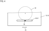
- step conveyor 1 In particular, if the step conveyor 1 is to be used in a clean room or for conveying food or medicines, a pneumatic drive would be disadvantageous, since escaping air could potentially lead to contamination. Therefore, an electric motor is used as actuator 12 in the step conveyor 1, which drives a rotating component 37, the rotation of which is shown schematically by the arrow 38. A projection 39 is arranged on the rotating component 37, which, as can be seen in particular in Fig.1 and 4 can be clearly seen, is guided through openings 40, 41 of the conveyor plates 15, 16.
- the movement of the projection 39 on a circular path 42 is shown schematically in Fig.4
- the dimensions of the openings 40, 41 are selected such that there is hardly any play of the projection 39 in relation to the opening 40, 41 in the conveying direction 17, while the projection 39 is freely movable in the transverse direction 43 over the entire movement distance achieved.
- the circular movement of the projection 39 is thus converted into a linear movement of the conveyor plates 15, 16 in the conveying direction 17.
Landscapes
- Engineering & Computer Science (AREA)
- Mechanical Engineering (AREA)
- Framework For Endless Conveyors (AREA)
- Escalators And Moving Walkways (AREA)
- Attitude Control For Articles On Conveyors (AREA)
Applications Claiming Priority (1)
| Application Number | Priority Date | Filing Date | Title |
|---|---|---|---|
| DE102021101108.6A DE102021101108A1 (de) | 2021-01-20 | 2021-01-20 | Stufenförderer, Stufenfördersystem und Verfahren zur Änderung der Stufenbreite eines Stufenförderers |
Publications (2)
| Publication Number | Publication Date |
|---|---|
| EP4032836A1 EP4032836A1 (de) | 2022-07-27 |
| EP4032836B1 true EP4032836B1 (de) | 2024-08-21 |
Family
ID=78592613
Family Applications (1)
| Application Number | Title | Priority Date | Filing Date |
|---|---|---|---|
| EP21207154.2A Active EP4032836B1 (de) | 2021-01-20 | 2021-11-09 | Stufenförderer, stufenfördersystem und verfahren zur änderung der stufenbreite eines stufenförderers |
Country Status (4)
| Country | Link |
|---|---|
| EP (1) | EP4032836B1 (da) |
| DE (1) | DE102021101108A1 (da) |
| DK (1) | DK4032836T3 (da) |
| ES (1) | ES2991511T3 (da) |
Families Citing this family (3)
| Publication number | Priority date | Publication date | Assignee | Title |
|---|---|---|---|---|
| CN116767804B (zh) * | 2023-07-25 | 2024-01-16 | 南京明盛制冷科技有限公司 | 一种制冷铜管加工的管件自动排序装置 |
| CN117262761B (zh) * | 2023-11-23 | 2024-02-20 | 海通安恒科技股份有限公司 | 一种智能制造生产线用产品输送装置 |
| CN120440569B (zh) * | 2025-07-10 | 2025-09-19 | 吉林省瑞航物流有限公司 | 一种钢材输送用防滑动装置 |
Family Cites Families (6)
| Publication number | Priority date | Publication date | Assignee | Title |
|---|---|---|---|---|
| US3665987A (en) * | 1968-06-13 | 1972-05-30 | Ralph K Daugherty | Shuffle feed positioner |
| DE3015785A1 (de) | 1980-04-24 | 1981-10-29 | MfM Maschinen- und Vorrichtungsbau für Montagetechnik GmbH, 8741 Saal | Foerder- und sortiergeraet |
| US5385227A (en) | 1993-07-29 | 1995-01-31 | Marsh; Robert A. | Elevating conveyor for small articles |
| KR100374690B1 (ko) | 1994-04-20 | 2003-05-01 | 리차드에취.제이.피에르켄스 | 밀봉형반도체칩의성형용자동펠릿공급장치와그방법 |
| DE102013112942B4 (de) | 2013-11-22 | 2021-08-19 | SIM Automation GmbH | Förder- und Sortiereinrichtung sowie Verfahren zum Fördern und Ausrichten von Gegenständen |
| CN106006075B (zh) * | 2016-07-08 | 2019-04-05 | 杨辰 | 前端旋转式推板上料器 |
-
2021
- 2021-01-20 DE DE102021101108.6A patent/DE102021101108A1/de active Pending
- 2021-11-09 DK DK21207154.2T patent/DK4032836T3/da active
- 2021-11-09 EP EP21207154.2A patent/EP4032836B1/de active Active
- 2021-11-09 ES ES21207154T patent/ES2991511T3/es active Active
Also Published As
| Publication number | Publication date |
|---|---|
| ES2991511T3 (es) | 2024-12-03 |
| DE102021101108A1 (de) | 2022-07-21 |
| DK4032836T3 (da) | 2024-11-11 |
| EP4032836A1 (de) | 2022-07-27 |
Similar Documents
| Publication | Publication Date | Title |
|---|---|---|
| EP4032836B1 (de) | Stufenförderer, stufenfördersystem und verfahren zur änderung der stufenbreite eines stufenförderers | |
| AT413505B (de) | Fertigungsanlage für die montage und/oder bearbeitung von auf werkstückträgern transportierten bauteilen | |
| EP1708815B1 (de) | Einseitig doppelt aufklappbarer rahmen für walzenpresse | |
| AT512898B1 (de) | Richtrolleneinheit | |
| DE3885442T2 (de) | Walzenbrecher und brechverfahren mit anwendung desselben. | |
| CH653945A5 (de) | Stanzeinrichtung. | |
| EP2338616A2 (de) | Maschineller Auflageleisten-Reiniger zum Reinigen von Auflageleisten von Werkstückauflagen an Werkzeugmaschinen | |
| EP2008799A1 (de) | Stanzpresse | |
| EP3256273B1 (de) | Stanzpressenanordnung | |
| DE10205092A1 (de) | Backenbrecher mit durchgehender Antriebswelle | |
| DE69213685T2 (de) | Gerät zum Kassettenwechseln für Schrittbearbeitungssysteme | |
| DE202023100126U1 (de) | Schneidmessereinheit | |
| DE2643507A1 (de) | Vorrichtung zum schrittweisen vorschub von platten | |
| DE112006000448B4 (de) | Walzenpresse | |
| EP1572495A1 (de) | Vorfeld-fahrzeug mit schneckenantrieb | |
| EP0610480B1 (de) | Beschickungseinrichtung für innenmischer, schneckenextruder o. dgl. | |
| EP2192067A1 (de) | Stapelvorrichtung für Druckprodukte | |
| EP0114174A1 (de) | Presse zur Rahmenherstellung | |
| EP1256416B1 (de) | Kurbeltrieb zur Rückführung von Werkstücken | |
| DE202025104939U1 (de) | Spiralwellensiebvorrichtung | |
| EP1532871B1 (de) | Vorrichtung zum Verdichten von Tabak, Rippen oder dergleichen | |
| EP0335289A2 (de) | Presse zur Herstellung von plastischen Rohlingen | |
| DE102023100544A1 (de) | Schneidmessereinheit | |
| DE202025106895U1 (de) | Vorrichtung zum Stanzen von Kunststoffflaschen | |
| EP3512675A1 (de) | Überführungseinrichtung einer oder für eine fördervorrichtung, fördervorrichtung, produktionsanlage und verfahren zum betreiben einer produktionsanlage |
Legal Events
| Date | Code | Title | Description |
|---|---|---|---|
| PUAI | Public reference made under article 153(3) epc to a published international application that has entered the european phase |
Free format text: ORIGINAL CODE: 0009012 |
|
| STAA | Information on the status of an ep patent application or granted ep patent |
Free format text: STATUS: THE APPLICATION HAS BEEN PUBLISHED |
|
| AK | Designated contracting states |
Kind code of ref document: A1 Designated state(s): AL AT BE BG CH CY CZ DE DK EE ES FI FR GB GR HR HU IE IS IT LI LT LU LV MC MK MT NL NO PL PT RO RS SE SI SK SM TR |
|
| STAA | Information on the status of an ep patent application or granted ep patent |
Free format text: STATUS: REQUEST FOR EXAMINATION WAS MADE |
|
| 17P | Request for examination filed |
Effective date: 20230126 |
|
| RBV | Designated contracting states (corrected) |
Designated state(s): AL AT BE BG CH CY CZ DE DK EE ES FI FR GB GR HR HU IE IS IT LI LT LU LV MC MK MT NL NO PL PT RO RS SE SI SK SM TR |
|
| P01 | Opt-out of the competence of the unified patent court (upc) registered |
Effective date: 20230506 |
|
| GRAP | Despatch of communication of intention to grant a patent |
Free format text: ORIGINAL CODE: EPIDOSNIGR1 |
|
| STAA | Information on the status of an ep patent application or granted ep patent |
Free format text: STATUS: GRANT OF PATENT IS INTENDED |
|
| INTG | Intention to grant announced |
Effective date: 20240516 |
|
| GRAS | Grant fee paid |
Free format text: ORIGINAL CODE: EPIDOSNIGR3 |
|
| GRAA | (expected) grant |
Free format text: ORIGINAL CODE: 0009210 |
|
| STAA | Information on the status of an ep patent application or granted ep patent |
Free format text: STATUS: THE PATENT HAS BEEN GRANTED |
|
| AK | Designated contracting states |
Kind code of ref document: B1 Designated state(s): AL AT BE BG CH CY CZ DE DK EE ES FI FR GB GR HR HU IE IS IT LI LT LU LV MC MK MT NL NO PL PT RO RS SE SI SK SM TR |
|
| REG | Reference to a national code |
Ref country code: GB Ref legal event code: FG4D Free format text: NOT ENGLISH |
|
| REG | Reference to a national code |
Ref country code: CH Ref legal event code: EP |
|
| REG | Reference to a national code |
Ref country code: IE Ref legal event code: FG4D Free format text: LANGUAGE OF EP DOCUMENT: GERMAN |
|
| REG | Reference to a national code |
Ref country code: DE Ref legal event code: R096 Ref document number: 502021004847 Country of ref document: DE |
|
| REG | Reference to a national code |
Ref country code: DK Ref legal event code: T3 Effective date: 20241107 |
|
| REG | Reference to a national code |
Ref country code: NL Ref legal event code: FP |
|
| REG | Reference to a national code |
Ref country code: ES Ref legal event code: FG2A Ref document number: 2991511 Country of ref document: ES Kind code of ref document: T3 Effective date: 20241203 |
|
| REG | Reference to a national code |
Ref country code: LT Ref legal event code: MG9D |
|
| PG25 | Lapsed in a contracting state [announced via postgrant information from national office to epo] |
Ref country code: NO Free format text: LAPSE BECAUSE OF FAILURE TO SUBMIT A TRANSLATION OF THE DESCRIPTION OR TO PAY THE FEE WITHIN THE PRESCRIBED TIME-LIMIT Effective date: 20241121 |
|
| PG25 | Lapsed in a contracting state [announced via postgrant information from national office to epo] |
Ref country code: PT Free format text: LAPSE BECAUSE OF FAILURE TO SUBMIT A TRANSLATION OF THE DESCRIPTION OR TO PAY THE FEE WITHIN THE PRESCRIBED TIME-LIMIT Effective date: 20241223 Ref country code: FI Free format text: LAPSE BECAUSE OF FAILURE TO SUBMIT A TRANSLATION OF THE DESCRIPTION OR TO PAY THE FEE WITHIN THE PRESCRIBED TIME-LIMIT Effective date: 20240821 Ref country code: PL Free format text: LAPSE BECAUSE OF FAILURE TO SUBMIT A TRANSLATION OF THE DESCRIPTION OR TO PAY THE FEE WITHIN THE PRESCRIBED TIME-LIMIT Effective date: 20240821 Ref country code: GR Free format text: LAPSE BECAUSE OF FAILURE TO SUBMIT A TRANSLATION OF THE DESCRIPTION OR TO PAY THE FEE WITHIN THE PRESCRIBED TIME-LIMIT Effective date: 20241122 |
|
| PG25 | Lapsed in a contracting state [announced via postgrant information from national office to epo] |
Ref country code: BG Free format text: LAPSE BECAUSE OF FAILURE TO SUBMIT A TRANSLATION OF THE DESCRIPTION OR TO PAY THE FEE WITHIN THE PRESCRIBED TIME-LIMIT Effective date: 20240821 |
|
| PG25 | Lapsed in a contracting state [announced via postgrant information from national office to epo] |
Ref country code: LV Free format text: LAPSE BECAUSE OF FAILURE TO SUBMIT A TRANSLATION OF THE DESCRIPTION OR TO PAY THE FEE WITHIN THE PRESCRIBED TIME-LIMIT Effective date: 20240821 |
|
| PG25 | Lapsed in a contracting state [announced via postgrant information from national office to epo] |
Ref country code: IS Free format text: LAPSE BECAUSE OF FAILURE TO SUBMIT A TRANSLATION OF THE DESCRIPTION OR TO PAY THE FEE WITHIN THE PRESCRIBED TIME-LIMIT Effective date: 20241221 |
|
| PG25 | Lapsed in a contracting state [announced via postgrant information from national office to epo] |
Ref country code: HR Free format text: LAPSE BECAUSE OF FAILURE TO SUBMIT A TRANSLATION OF THE DESCRIPTION OR TO PAY THE FEE WITHIN THE PRESCRIBED TIME-LIMIT Effective date: 20240821 |
|
| PG25 | Lapsed in a contracting state [announced via postgrant information from national office to epo] |
Ref country code: RS Free format text: LAPSE BECAUSE OF FAILURE TO SUBMIT A TRANSLATION OF THE DESCRIPTION OR TO PAY THE FEE WITHIN THE PRESCRIBED TIME-LIMIT Effective date: 20241121 |
|
| PG25 | Lapsed in a contracting state [announced via postgrant information from national office to epo] |
Ref country code: RS Free format text: LAPSE BECAUSE OF FAILURE TO SUBMIT A TRANSLATION OF THE DESCRIPTION OR TO PAY THE FEE WITHIN THE PRESCRIBED TIME-LIMIT Effective date: 20241121 Ref country code: PT Free format text: LAPSE BECAUSE OF FAILURE TO SUBMIT A TRANSLATION OF THE DESCRIPTION OR TO PAY THE FEE WITHIN THE PRESCRIBED TIME-LIMIT Effective date: 20241223 Ref country code: PL Free format text: LAPSE BECAUSE OF FAILURE TO SUBMIT A TRANSLATION OF THE DESCRIPTION OR TO PAY THE FEE WITHIN THE PRESCRIBED TIME-LIMIT Effective date: 20240821 Ref country code: NO Free format text: LAPSE BECAUSE OF FAILURE TO SUBMIT A TRANSLATION OF THE DESCRIPTION OR TO PAY THE FEE WITHIN THE PRESCRIBED TIME-LIMIT Effective date: 20241121 Ref country code: LV Free format text: LAPSE BECAUSE OF FAILURE TO SUBMIT A TRANSLATION OF THE DESCRIPTION OR TO PAY THE FEE WITHIN THE PRESCRIBED TIME-LIMIT Effective date: 20240821 Ref country code: IS Free format text: LAPSE BECAUSE OF FAILURE TO SUBMIT A TRANSLATION OF THE DESCRIPTION OR TO PAY THE FEE WITHIN THE PRESCRIBED TIME-LIMIT Effective date: 20241221 Ref country code: HR Free format text: LAPSE BECAUSE OF FAILURE TO SUBMIT A TRANSLATION OF THE DESCRIPTION OR TO PAY THE FEE WITHIN THE PRESCRIBED TIME-LIMIT Effective date: 20240821 Ref country code: GR Free format text: LAPSE BECAUSE OF FAILURE TO SUBMIT A TRANSLATION OF THE DESCRIPTION OR TO PAY THE FEE WITHIN THE PRESCRIBED TIME-LIMIT Effective date: 20241122 Ref country code: FI Free format text: LAPSE BECAUSE OF FAILURE TO SUBMIT A TRANSLATION OF THE DESCRIPTION OR TO PAY THE FEE WITHIN THE PRESCRIBED TIME-LIMIT Effective date: 20240821 Ref country code: BG Free format text: LAPSE BECAUSE OF FAILURE TO SUBMIT A TRANSLATION OF THE DESCRIPTION OR TO PAY THE FEE WITHIN THE PRESCRIBED TIME-LIMIT Effective date: 20240821 |
|
| PG25 | Lapsed in a contracting state [announced via postgrant information from national office to epo] |
Ref country code: SM Free format text: LAPSE BECAUSE OF FAILURE TO SUBMIT A TRANSLATION OF THE DESCRIPTION OR TO PAY THE FEE WITHIN THE PRESCRIBED TIME-LIMIT Effective date: 20240821 Ref country code: RO Free format text: LAPSE BECAUSE OF FAILURE TO SUBMIT A TRANSLATION OF THE DESCRIPTION OR TO PAY THE FEE WITHIN THE PRESCRIBED TIME-LIMIT Effective date: 20240821 |
|
| PG25 | Lapsed in a contracting state [announced via postgrant information from national office to epo] |
Ref country code: EE Free format text: LAPSE BECAUSE OF FAILURE TO SUBMIT A TRANSLATION OF THE DESCRIPTION OR TO PAY THE FEE WITHIN THE PRESCRIBED TIME-LIMIT Effective date: 20240821 |
|
| PG25 | Lapsed in a contracting state [announced via postgrant information from national office to epo] |
Ref country code: CZ Free format text: LAPSE BECAUSE OF FAILURE TO SUBMIT A TRANSLATION OF THE DESCRIPTION OR TO PAY THE FEE WITHIN THE PRESCRIBED TIME-LIMIT Effective date: 20240821 |
|
| PG25 | Lapsed in a contracting state [announced via postgrant information from national office to epo] |
Ref country code: SK Free format text: LAPSE BECAUSE OF FAILURE TO SUBMIT A TRANSLATION OF THE DESCRIPTION OR TO PAY THE FEE WITHIN THE PRESCRIBED TIME-LIMIT Effective date: 20240821 |
|
| REG | Reference to a national code |
Ref country code: DE Ref legal event code: R097 Ref document number: 502021004847 Country of ref document: DE |
|
| REG | Reference to a national code |
Ref country code: DK Ref legal event code: EBP Effective date: 20241130 |
|
| PLBE | No opposition filed within time limit |
Free format text: ORIGINAL CODE: 0009261 |
|
| STAA | Information on the status of an ep patent application or granted ep patent |
Free format text: STATUS: NO OPPOSITION FILED WITHIN TIME LIMIT |
|
| PG25 | Lapsed in a contracting state [announced via postgrant information from national office to epo] |
Ref country code: MC Free format text: LAPSE BECAUSE OF FAILURE TO SUBMIT A TRANSLATION OF THE DESCRIPTION OR TO PAY THE FEE WITHIN THE PRESCRIBED TIME-LIMIT Effective date: 20240821 |
|
| REG | Reference to a national code |
Ref country code: NL Ref legal event code: MM Effective date: 20241201 |
|
| PG25 | Lapsed in a contracting state [announced via postgrant information from national office to epo] |
Ref country code: LU Free format text: LAPSE BECAUSE OF NON-PAYMENT OF DUE FEES Effective date: 20241109 |
|
| 26N | No opposition filed |
Effective date: 20250522 |
|
| PG25 | Lapsed in a contracting state [announced via postgrant information from national office to epo] |
Ref country code: NL Free format text: LAPSE BECAUSE OF NON-PAYMENT OF DUE FEES Effective date: 20241201 |
|
| REG | Reference to a national code |
Ref country code: BE Ref legal event code: MM Effective date: 20241130 |
|
| PG25 | Lapsed in a contracting state [announced via postgrant information from national office to epo] |
Ref country code: SE Free format text: LAPSE BECAUSE OF FAILURE TO SUBMIT A TRANSLATION OF THE DESCRIPTION OR TO PAY THE FEE WITHIN THE PRESCRIBED TIME-LIMIT Effective date: 20240821 |
|
| PG25 | Lapsed in a contracting state [announced via postgrant information from national office to epo] |
Ref country code: DK Free format text: LAPSE BECAUSE OF NON-PAYMENT OF DUE FEES Effective date: 20241130 |
|
| PG25 | Lapsed in a contracting state [announced via postgrant information from national office to epo] |
Ref country code: BE Free format text: LAPSE BECAUSE OF NON-PAYMENT OF DUE FEES Effective date: 20241130 |
|
| PG25 | Lapsed in a contracting state [announced via postgrant information from national office to epo] |
Ref country code: IE Free format text: LAPSE BECAUSE OF NON-PAYMENT OF DUE FEES Effective date: 20241109 |
|
| REG | Reference to a national code |
Ref country code: DE Ref legal event code: R082 Ref document number: 502021004847 Country of ref document: DE Representative=s name: BBS BIER BREHM SPAHN PARTNERSCHAFT RECHTSANWAE, DE |
|
| REG | Reference to a national code |
Ref country code: CH Ref legal event code: U11 Free format text: ST27 STATUS EVENT CODE: U-0-0-U10-U11 (AS PROVIDED BY THE NATIONAL OFFICE) Effective date: 20251201 |
|
| REG | Reference to a national code |
Ref country code: ES Ref legal event code: FD2A Effective date: 20251230 |
|
| PGFP | Annual fee paid to national office [announced via postgrant information from national office to epo] |
Ref country code: DE Payment date: 20251022 Year of fee payment: 5 |
|
| PGFP | Annual fee paid to national office [announced via postgrant information from national office to epo] |
Ref country code: GB Payment date: 20251023 Year of fee payment: 5 |
|
| PGFP | Annual fee paid to national office [announced via postgrant information from national office to epo] |
Ref country code: AT Payment date: 20260113 Year of fee payment: 5 |
|
| PGFP | Annual fee paid to national office [announced via postgrant information from national office to epo] |
Ref country code: IT Payment date: 20251022 Year of fee payment: 5 |
|
| PGFP | Annual fee paid to national office [announced via postgrant information from national office to epo] |
Ref country code: FR Payment date: 20251022 Year of fee payment: 5 |
|
| PGFP | Annual fee paid to national office [announced via postgrant information from national office to epo] |
Ref country code: CH Payment date: 20251201 Year of fee payment: 5 |
|
| PG25 | Lapsed in a contracting state [announced via postgrant information from national office to epo] |
Ref country code: ES Free format text: LAPSE BECAUSE OF NON-PAYMENT OF DUE FEES Effective date: 20241110 |
|
| PG25 | Lapsed in a contracting state [announced via postgrant information from national office to epo] |
Ref country code: HU Free format text: LAPSE BECAUSE OF FAILURE TO SUBMIT A TRANSLATION OF THE DESCRIPTION OR TO PAY THE FEE WITHIN THE PRESCRIBED TIME-LIMIT; INVALID AB INITIO Effective date: 20211109 |
|
| PG25 | Lapsed in a contracting state [announced via postgrant information from national office to epo] |
Ref country code: CY Free format text: LAPSE BECAUSE OF FAILURE TO SUBMIT A TRANSLATION OF THE DESCRIPTION OR TO PAY THE FEE WITHIN THE PRESCRIBED TIME-LIMIT; INVALID AB INITIO Effective date: 20211109 |