EP4032837A1 - Pulverversorgungsgerät - Google Patents
Pulverversorgungsgerät Download PDFInfo
- Publication number
- EP4032837A1 EP4032837A1 EP20864614.1A EP20864614A EP4032837A1 EP 4032837 A1 EP4032837 A1 EP 4032837A1 EP 20864614 A EP20864614 A EP 20864614A EP 4032837 A1 EP4032837 A1 EP 4032837A1
- Authority
- EP
- European Patent Office
- Prior art keywords
- powder
- recess
- measuring shaft
- supply apparatus
- cylinder
- Prior art date
- Legal status (The legal status is an assumption and is not a legal conclusion. Google has not performed a legal analysis and makes no representation as to the accuracy of the status listed.)
- Pending
Links
Images


Classifications
-
- B—PERFORMING OPERATIONS; TRANSPORTING
- B65—CONVEYING; PACKING; STORING; HANDLING THIN OR FILAMENTARY MATERIAL
- B65G—TRANSPORT OR STORAGE DEVICES, e.g. CONVEYORS FOR LOADING OR TIPPING, SHOP CONVEYOR SYSTEMS OR PNEUMATIC TUBE CONVEYORS
- B65G65/00—Loading or unloading
- B65G65/30—Methods or devices for filling or emptying bunkers, hoppers, tanks, or like containers, of interest apart from their use in particular chemical or physical processes or their application in particular machines, e.g. not covered by a single other subclass
- B65G65/34—Emptying devices
- B65G65/40—Devices for emptying otherwise than from the top
- B65G65/44—Devices for emptying otherwise than from the top using reciprocating conveyors, e.g. jigging conveyors
-
- B—PERFORMING OPERATIONS; TRANSPORTING
- B22—CASTING; POWDER METALLURGY
- B22F—WORKING METALLIC POWDER; MANUFACTURE OF ARTICLES FROM METALLIC POWDER; MAKING METALLIC POWDER; APPARATUS OR DEVICES SPECIALLY ADAPTED FOR METALLIC POWDER
- B22F12/00—Apparatus or devices specially adapted for additive manufacturing; Auxiliary means for additive manufacturing; Combinations of additive manufacturing apparatus or devices with other processing apparatus or devices
- B22F12/50—Means for feeding of material, e.g. heads
-
- G—PHYSICS
- G01—MEASURING; TESTING
- G01F—MEASURING VOLUME, VOLUME FLOW, MASS FLOW OR LIQUID LEVEL; METERING BY VOLUME
- G01F11/00—Apparatus requiring external operation adapted at each repeated and identical operation to measure and separate a predetermined volume of fluid or fluent solid material from a supply or container, without regard to weight, and to deliver it
- G01F11/10—Apparatus requiring external operation adapted at each repeated and identical operation to measure and separate a predetermined volume of fluid or fluent solid material from a supply or container, without regard to weight, and to deliver it with measuring chambers moved during operation
- G01F11/26—Apparatus requiring external operation adapted at each repeated and identical operation to measure and separate a predetermined volume of fluid or fluent solid material from a supply or container, without regard to weight, and to deliver it with measuring chambers moved during operation wherein the measuring chamber is filled and emptied by tilting or inverting the supply vessel, e.g. bottle-emptying apparatus
- G01F11/261—Apparatus requiring external operation adapted at each repeated and identical operation to measure and separate a predetermined volume of fluid or fluent solid material from a supply or container, without regard to weight, and to deliver it with measuring chambers moved during operation wherein the measuring chamber is filled and emptied by tilting or inverting the supply vessel, e.g. bottle-emptying apparatus for fluent solid material
-
- B—PERFORMING OPERATIONS; TRANSPORTING
- B22—CASTING; POWDER METALLURGY
- B22F—WORKING METALLIC POWDER; MANUFACTURE OF ARTICLES FROM METALLIC POWDER; MAKING METALLIC POWDER; APPARATUS OR DEVICES SPECIALLY ADAPTED FOR METALLIC POWDER
- B22F12/00—Apparatus or devices specially adapted for additive manufacturing; Auxiliary means for additive manufacturing; Combinations of additive manufacturing apparatus or devices with other processing apparatus or devices
- B22F12/50—Means for feeding of material, e.g. heads
- B22F12/57—Metering means
-
- B—PERFORMING OPERATIONS; TRANSPORTING
- B29—WORKING OF PLASTICS; WORKING OF SUBSTANCES IN A PLASTIC STATE IN GENERAL
- B29C—SHAPING OR JOINING OF PLASTICS; SHAPING OF MATERIAL IN A PLASTIC STATE, NOT OTHERWISE PROVIDED FOR; AFTER-TREATMENT OF THE SHAPED PRODUCTS, e.g. REPAIRING
- B29C64/00—Additive manufacturing, i.e. manufacturing of three-dimensional [3D] objects by additive deposition, additive agglomeration or additive layering, e.g. by 3D printing, stereolithography or selective laser sintering
- B29C64/30—Auxiliary operations or equipment
- B29C64/307—Handling of material to be used in additive manufacturing
- B29C64/321—Feeding
-
- B—PERFORMING OPERATIONS; TRANSPORTING
- B29—WORKING OF PLASTICS; WORKING OF SUBSTANCES IN A PLASTIC STATE IN GENERAL
- B29C—SHAPING OR JOINING OF PLASTICS; SHAPING OF MATERIAL IN A PLASTIC STATE, NOT OTHERWISE PROVIDED FOR; AFTER-TREATMENT OF THE SHAPED PRODUCTS, e.g. REPAIRING
- B29C64/00—Additive manufacturing, i.e. manufacturing of three-dimensional [3D] objects by additive deposition, additive agglomeration or additive layering, e.g. by 3D printing, stereolithography or selective laser sintering
- B29C64/30—Auxiliary operations or equipment
- B29C64/307—Handling of material to be used in additive manufacturing
- B29C64/343—Metering
-
- B—PERFORMING OPERATIONS; TRANSPORTING
- B33—ADDITIVE MANUFACTURING TECHNOLOGY
- B33Y—ADDITIVE MANUFACTURING, i.e. MANUFACTURING OF THREE-DIMENSIONAL [3D] OBJECTS BY ADDITIVE DEPOSITION, ADDITIVE AGGLOMERATION OR ADDITIVE LAYERING, e.g. BY 3D PRINTING, STEREOLITHOGRAPHY OR SELECTIVE LASER SINTERING
- B33Y30/00—Apparatus for additive manufacturing; Details thereof or accessories therefor
-
- B—PERFORMING OPERATIONS; TRANSPORTING
- B65—CONVEYING; PACKING; STORING; HANDLING THIN OR FILAMENTARY MATERIAL
- B65G—TRANSPORT OR STORAGE DEVICES, e.g. CONVEYORS FOR LOADING OR TIPPING, SHOP CONVEYOR SYSTEMS OR PNEUMATIC TUBE CONVEYORS
- B65G65/00—Loading or unloading
- B65G65/30—Methods or devices for filling or emptying bunkers, hoppers, tanks, or like containers, of interest apart from their use in particular chemical or physical processes or their application in particular machines, e.g. not covered by a single other subclass
- B65G65/34—Emptying devices
- B65G65/40—Devices for emptying otherwise than from the top
- B65G65/48—Devices for emptying otherwise than from the top using other rotating means, e.g. rotating pressure sluices in pneumatic systems
- B65G65/4881—Devices for emptying otherwise than from the top using other rotating means, e.g. rotating pressure sluices in pneumatic systems rotating about a substantially horizontal axis
-
- G—PHYSICS
- G01—MEASURING; TESTING
- G01F—MEASURING VOLUME, VOLUME FLOW, MASS FLOW OR LIQUID LEVEL; METERING BY VOLUME
- G01F11/00—Apparatus requiring external operation adapted at each repeated and identical operation to measure and separate a predetermined volume of fluid or fluent solid material from a supply or container, without regard to weight, and to deliver it
- G01F11/10—Apparatus requiring external operation adapted at each repeated and identical operation to measure and separate a predetermined volume of fluid or fluent solid material from a supply or container, without regard to weight, and to deliver it with measuring chambers moved during operation
- G01F11/12—Apparatus requiring external operation adapted at each repeated and identical operation to measure and separate a predetermined volume of fluid or fluent solid material from a supply or container, without regard to weight, and to deliver it with measuring chambers moved during operation of the valve type, i.e. the separating being effected by fluid-tight or powder-tight movements
- G01F11/20—Apparatus requiring external operation adapted at each repeated and identical operation to measure and separate a predetermined volume of fluid or fluent solid material from a supply or container, without regard to weight, and to deliver it with measuring chambers moved during operation of the valve type, i.e. the separating being effected by fluid-tight or powder-tight movements wherein the measuring chamber rotates or oscillates
- G01F11/24—Apparatus requiring external operation adapted at each repeated and identical operation to measure and separate a predetermined volume of fluid or fluent solid material from a supply or container, without regard to weight, and to deliver it with measuring chambers moved during operation of the valve type, i.e. the separating being effected by fluid-tight or powder-tight movements wherein the measuring chamber rotates or oscillates for fluent solid material
-
- B—PERFORMING OPERATIONS; TRANSPORTING
- B65—CONVEYING; PACKING; STORING; HANDLING THIN OR FILAMENTARY MATERIAL
- B65G—TRANSPORT OR STORAGE DEVICES, e.g. CONVEYORS FOR LOADING OR TIPPING, SHOP CONVEYOR SYSTEMS OR PNEUMATIC TUBE CONVEYORS
- B65G2201/00—Indexing codes relating to handling devices, e.g. conveyors, characterised by the type of product or load being conveyed or handled
- B65G2201/04—Bulk
- B65G2201/042—Granular material
-
- G—PHYSICS
- G01—MEASURING; TESTING
- G01F—MEASURING VOLUME, VOLUME FLOW, MASS FLOW OR LIQUID LEVEL; METERING BY VOLUME
- G01F23/00—Indicating or measuring liquid level or level of fluent solid material, e.g. indicating in terms of volume or indicating by means of an alarm
Definitions
- the present invention relates to a powder supply apparatus.
- Solid materials obtained by applying a high pressure to evenly spread powder have been recently used for industrial application. Such solid materials typically need, for example, highly accurate shapes. Thus, a constant amount of powder is necessary for forming the solid materials.
- apparatuses for supplying powder powder supply apparatuses as uniformly as possible are used for apparatuses for forming the solid materials.
- Patent Literature 1 Japanese Patent Laid-Open No. 2016-147253 proposes a conventional powder supply apparatus that securely supplies powder by dropping the powder from a measuring recess of a rod-like member.
- the powder supply apparatus described in Patent Literature 1 discharges air from the measuring recess, thereby securely dropping powder from the measuring recess.
- powder in the measuring recess of the rod-like member is dropped and supplied therefrom by rotating the rod-like member about the axis 180° at an original position of the rod-like member.
- the powder may be supplied from the measuring recess before the measuring recess is filled with a fixed amount of the powder.
- powder having small particle diameters may adhere to a portion other than the measuring recess of the rod-like member by, for example, the powder entering between the rod-like member and a sliding contact portion, and the powder adhering to the rod-like member may be supplied together with the powder in the measuring recess.
- Patent Literature 1 various configurations such as a powder agitation mechanism 50 and a hopper unit 21 for filling a measuring recess 34 with powder are required above a predetermined position for supplying powder, as illustrated in FIG. 1 of Patent Literature 1.
- a space above the predetermined position for supplying powder is necessary for a downstream process (e.g., a process for spreading powder) of the powder supply apparatus. The absence of such a space may limit apparatuses to be used in the downstream process.
- an object of present invention is to provide a powder supply apparatus that can supply even a fixed trace amount of powder and secure a space above a predetermined position for supplying powder.
- a powder supply apparatus includes:
- a powder supply apparatus according to a second invention, wherein the powder filling mechanism in the powder supply apparatus according to the first invention includes:
- a powder supply apparatus according to a third invention, wherein the powder filling mechanism in the powder supply apparatus according to the second invention further includes a powder agitator blade projecting from the inner surface of the cylinder.
- a powder supply apparatus according to a fourth invention, wherein the powder filling mechanism in the powder supply apparatus according to one of the second and third inventions further includes an air blowing unit that agitates the powder by blowing air in the cylinder.
- a powder supply apparatus according to a fifth invention, wherein the leveling member in the powder supply apparatus according to one of the second and third inventions is a member having a shaft through hole for guiding the recess of the measuring shaft from the inside to the outside of the cylinder by the slide of the measuring shaft.
- a powder supply apparatus in the powder supply apparatus according to any one of the first to third inventions, further includes a shaft vibration mechanism for facilitating the drop of the powder from the recess facing downward by vibrations.
- a powder supply apparatus includes, in the powder supply apparatus according to any one of the first to third inventions, a detector for detecting a filling state of the powder in the recess after the powder is leveled off by the leveling member; and a control mechanism that causes the slide mechanism to slide the measuring shaft to a position for filling the recess with the powder and causes the powder filling mechanism to fill the recess with the powder if the detector detects an insufficient filling state of the powder.
- the powder supply apparatus supplies powder leveled off by the leveling member, so that even a fixed trace amount of the powder can be supplied. Moreover, the powder is supplied from the recess after being slid from a position for filling the recess with the powder, thereby securing a space above the predetermined position for supplying the powder.
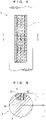
- FIGS. 1 to 3 are schematic side views of the powder supply apparatus.
- a powder supply apparatus 1 includes a measuring shaft 2 having a recess 3 to be filled with powder P, and a powder filling mechanism 5 for filling the recess 3 of the measuring shaft 2 with the powder P.
- the powder supply apparatus 1 includes a slide mechanism 6 for sliding the measuring shaft 2 along an axis 4 of the measuring shaft 2, and a leveling member 7 for leveling off the powder P in the recess 3 by a slide of the measuring shaft 2. Furthermore, as illustrated in FIG.
- the powder supply apparatus 1 includes an axial rotation mechanism 8 that directs the recess 3 downward by rotating the measuring shaft 2 about the axis 4 and supplies the leveled powder P in the recess 3 downward from the recess 3 to a predetermined position 10 by dropping the powder P.
- the powder filling mechanism 5 fills the recess 3 of the measuring shaft 2 with the powder P as illustrated in FIG. 1 .
- the powder P in the recess 3 may protrude from the recess 3.
- the slide mechanism 6 slides the measuring shaft 2, causing the leveling member 7 to level off the powder P in the recess 3.
- the leveling causes a protruding portion of the powder P from the recess 3 to drop from the recess 3.
- the axial rotation mechanism 8 rotates the measuring shaft 2 about the axis 4 so as to direct the recess 3 downward.
- the powder P drops downward from the recess 3 facing downward, so that the powder P is supplied to the predetermined position 10 below the recess 3.
- FIG. 4 is a plan view of the measuring shaft 2
- FIG. 5 is a cross-sectional view taken along line A-A of FIG. 4
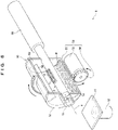
- FIG. 6 is a partially cut perspective view of the powder supply apparatus 1.
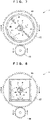
- FIGS. 7 and 8 are cross-sectional views of the powder filling mechanism 5
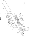
- FIGS. 9 and 10 are partially cut perspective views of the powder supply apparatus 1
- FIG. 11 illustrates a cross section of the measuring shaft 2 and another configuration.
- the recess 3 of the measuring shaft 2 is, for example, rectangular in plan view.
- the rectangular shape is preferably extended with a ratio of about 1:20 to 1:40 between the short side and the long side.
- the extended recess 3 in plan view causes the powder P supplied from the recess 3 to extend like the recess 3 in plan view, so that the supplied powder P is suitably shaped to be spread by a squeegee or the like in a downstream process. In other words, this is because the powder P can be evenly supplied along the width direction of a squeegee or the like.
- the recess 3 is not always rectangular in plan view and may have any other shapes like an ellipse or an oval.
- the recess 3 of the measuring shaft 2 is an opening with sides 32 and a bottom 33.
- An angle ⁇ formed between the side 32 and the bottom 33 of the recess 3 is preferably an obtuse angle. If the angle ⁇ is an obtuse angle, the powder P easily falls from the recess 3 facing downward. If the powder P easily falls from the recess 3 facing downward, the powder P is hardly left in the recess 3 facing downward, so that even a fixed trace amount of the powder P can be supplied.
- the bottom 33 of the recess 3 is preferably shallower than the axis 4 of the measuring shaft 2 (h ⁇ r). This is because the bottom 33 at a lesser depth causes the powder P in the recess 3 to receive a centrifugal force applied from the measuring shaft 2 rotated by the axial rotation mechanism 8 and the powder P easily falls from the recess 3 facing downward.
- the powder filling mechanism 5 includes, for example, a cylinder 50 in which the recess 3 of the measuring shaft 2 can be placed.
- the powder P is placed in the cylinder 50.
- the illustrated cylinder 50 is cut in half lengthwise to indicate the inside of the cylinder 50.
- the powder filling mechanism 5 includes, for example, a cylinder rotation mechanism 54 for rotating the cylinder 50.
- the cylinder rotation mechanism 54 rotates the cylinder 50 so as to agitate the powder P, and then the agitated powder P fills the recess 3.
- the cylinder rotation mechanism 54 includes, for example, a driving gear 56 connected to the output shaft of a motor 55 and a driven gear 57 that is engaged with the driving gear 56 and is attached to the outer surface of the cylinder 50.
- the powder filling mechanism 5 further includes, for example, powder agitator blades 58 projecting from the inner surface of the cylinder 50.
- the powder agitator blades 58 accelerate the agitation of the powder P in the cylinder 50 in response to a rotation of the cylinder 50.
- the acceleration of the agitation of the powder P smashes clumps of the powder P, so that even a fixed trace amount of the powder P can be supplied.
- the multiple (two in the example of FIG. 7 ) powder agitator blades 58 are preferably provided to further accelerate agitation.
- the blades are more preferably disposed at regular intervals.
- At least one of the powder agitator blades 58 preferably has a length such that a tip of the one of the powder agitator blades 58 is separated from the measuring shaft 2 by only a small distance (d) (that is, the long powder agitator blade 58).
- This configuration allows the long powder agitator blade 58 to rotate to level off the powder P that fills the recess 3 and protrudes from the outer surface of the measuring shaft 2, so that the recess 3 is stably filled with the powder P.
- the distance (d) between the long powder agitator blade 58 and the measuring shaft 2 is preferably equal to or smaller than a depth (h) of the recess 3.
- the cylinder 50 may be circular or polygonal (square in the example of FIG.
- the cylinder 50 shaped like a polygon, e.g., a square in cross section easily transports the powder P upward from a corner of the cylinder 50 in response to a rotation of the cylinder 50, thereby accelerating the agitation of the powder P.
- the powder filling mechanism 5 includes, for example, an air blowing unit 59 that agitates the powder P by blowing air a in the cylinder 50.
- the cylinder 50, in which the air blowing unit 59 blows the air a may have any shapes in addition to a square in cross section in FIG. 8 .
- the powder supply apparatus 1 includes a rotary cylinder 68 that slides the measuring shaft 2 along the axis 4 and rotates the measuring shaft 2 about the axis 4.
- the rotary cylinder 68 acts as the slide mechanism 6 and the axial rotation mechanism 8.
- the cylinder 50 includes a body 51, a proximal-end cover plate 52 that is disposed on one end of the body 51 and through which the proximal end of the measuring shaft 2 penetrates, a distal-end cover plate 72 that is disposed on the other end of the body 51 and through which the distal end of the measuring shaft 2 is allowed to penetrate, and a boss member 73 that is provided on the outer surface of the distal-end cover plate 72 and through which the distal end of the measuring shaft 2 is allowed to penetrate.
- a shaft through hole 74 formed in the distal-end cover plate 72 and the boss member 73 is a space for guiding the recess 3 of the measuring shaft 2 from the inside to the outside of the cylinder 50 by a slide of the measuring shaft 2.
- the distal-end cover plate 72 and the boss member 73 that have the shaft through hole 74 correspond to the leveling member 7. If the distal-end cover plate 72 and the boss member 73 are not integrated but are provided as different members, the powder P in the recess 3 is actually leveled off by the distal-end cover plate 72 facing the inside of the cylinder 50. Thus, the distal-end cover plate 72 corresponds to the leveling member 7.
- the cross section of the shaft through hole 74 is preferably as large as or slightly larger than the cross section of the measuring shaft 2 (for example, by a tolerance).
- the shaft through hole 74 configured thus reduces variations in the amount of the powder P that is leveled off and left in the recess 3. By reducing variations in the amount of the powder P that is leveled off and left in the recess 3, even a fixed trace amount of the powder P can be supplied.
- a lifting plate 11 may be provided as the predetermined position 10 where the dropped powder P is supplied from the recess 3, and a lifting cylinder 12 may be provided to lift and lower the lifting plate 11.
- the lifting cylinder 12 can lift the lifting plate 11 to a proper height of the lifting plate 11 when the powder P is supplied from the recess 3.
- the height of the lifting plate 11 is preferably set such that a distance (h + ⁇ ) between the lower end of the measuring shaft 2 and a surface on which the powder P is supplied from the recess 3 is larger than a depth (h) of the recess 3 by a small distance ( ⁇ ).
- the height can minimize a drop height (h + ⁇ ) of the powder P dropped from the recess 3, so that the supplied powder P is not deformed by the drop and is suitably shaped to be spread by a squeegee or the like in a downstream process.
- a shaft vibration mechanism 9 for vibrating the measuring shaft 2 may be provided.
- the shaft vibration mechanism 9 facilitates the drop of the powder P from the recess 3 by vibrating the measuring shaft 2 with the recess 3 facing downward.
- a method of using the powder supply apparatus 1 will be specifically described below.
- the cylinder 50 is rotated by the cylinder rotation mechanism 54.
- the powder P disposed in the cylinder 50 is agitated by the rotation.
- the agitated powder P rises above the recess 3 of the measuring shaft 2, so that the recess 3 is filled with the powder P.
- the measuring shaft 2 is slid by the rotary cylinder 68 as illustrated in FIG. 9 .
- a time when the powder P filling the recess 3 protrudes therefrom can be estimated from the number of revolutions or the time of revolution of the cylinder 50.
- the measuring shaft 2 may be automatically slid by the rotary cylinder 68.
- the slide of the measuring shaft 2 moves the recess 3 from the inside to the outside of the cylinder 50 through the shaft through hole 74.
- the recess 3 passes through the shaft through hole 74, the powder P protruding from the recess 3 is leveled off.
- the recess 3 moves out of the cylinder 50 while the powder P filling the recess 3 is leveled off.
- the lifting plate 11 is lifted by the lifting cylinder 12. Specifically, as illustrated in FIG. 11 , the lifting plate 11 is lifted to the preferable height.
- the rotary cylinder 68 rotates the measuring shaft 2 about the axis 4 so as to direct the recess 3 downward.
- the measuring shaft 2 may be automatically rotated about the axis 4 by the rotary cylinder 68.
- the powder P drops to the lifting plate 11 from the recess 3 facing downward, so that the powder P is supplied to the lifting plate 11.
- the shaft vibration mechanism 9 vibrates the measuring shaft 2 with the recess 3 facing downward.
- the powder supply apparatus 1 supplies the powder P leveled off by the leveling member 7, so that even a fixed trace amount of the powder P can be supplied. Moreover, the powder P is supplied from the recess 3 after being slid from a position for filling the recess 3 with the powder P, thereby securing a space above the predetermined position 10 for supplying the powder P.
- the cylinder 50 with the powder P disposed therein is rotated by the cylinder rotation mechanism 54, thereby agitating the powder P in the cylinder 50 so as to smash clumps of the powder P.
- the cylinder 50 with the powder P disposed therein is rotated by the cylinder rotation mechanism 54, allowing estimation of a time when the recess 3 is filled with the powder P.
- the configuration can be suitable for automation.
- the agitation of the powder P is accelerated by the powder agitator blades 58 and the air blowing unit 59 in the cylinder 50 so as to further smash clumps of the powder P.
- the powder agitator blades 58 and the air blowing unit 59 in the cylinder 50 so as to further smash clumps of the powder P.
- the leveling member 7 is a member (distal-end cover plate 72) constituting the cylinder 50, achieving a simple configuration.
- the shaft vibration mechanism 9 vibrating the measuring shaft 2 easily drops the powder P from the recess 3 facing downward, so that even a fixed trace amount of the powder P can be supplied.
- the powder P is not specifically described in the present embodiment.
- the powder P may be any powder and is not limited.
- the preferable powder P supplied in the powder supply apparatus 1 is spread by a squeegee or the like in a downstream process and then is formed into a solid material under a high pressure.
- measuring shaft 2 circular in cross section is illustrated.
- the measuring shaft 2 may have other shapes such as a polygon.
- a filling state is preferably confirmed before the leveled powder P is supplied downward, though the confirmation is not described in the foregoing embodiment.
- the confirmation may be a visual check but is preferably made by devices in view of reliability and automation.
- configurations necessary for the confirmation by devices are a detector 30 and a control mechanism 65.
- the detector 30 detects a filling state of the powder P in the recess 3 after the powder P is leveled off by the leveling member 7.
- the detector 30 is, for example, a laser measuring machine or a camera (image detection) that measures the shape of the recess 3 or recognizes a state of filling of the recess 3 with the powder P.
- the control mechanism 65 causes the slide mechanism 6 to slide the measuring shaft 2 to a position for filling (refilling) the recess 3 with the powder P and causes the powder filling mechanism 5 to fill (refill) the recess 3 with the powder P.
- the insufficient filling state means that a necessary amount of the powder P for being supplied fixedly has not filled the recess 3.
- the control mechanism 65 is specifically, for example, a control panel including a determination unit for determining whether a filling state detected by the detector 30 is insufficient or not, and an instruction unit for providing instructions for the powder filling mechanism 5 and the slide mechanism 6.
- the detector 30 in FIG. 12 is oriented to detect a filling state of the powder P leveled off by the leveling member 7.
- the control mechanism 65 immediately refills the recess 3 with the powder P, thereby shortening a time for supplying a fixed amount of the powder P.
- the detector 30 in FIG. 13 is oriented to detect a filling state of the powder P immediately before the powder P is supplied downward. This can reliably supply a fixed amount of the powder P.
- the powder supply apparatus 1 may be provided with both of the detector 30 in FIG. 12 and the detector 30 in FIG. 13 .
Landscapes
- Engineering & Computer Science (AREA)
- Chemical & Material Sciences (AREA)
- Materials Engineering (AREA)
- Manufacturing & Machinery (AREA)
- Physics & Mathematics (AREA)
- Mechanical Engineering (AREA)
- Fluid Mechanics (AREA)
- General Physics & Mathematics (AREA)
- Optics & Photonics (AREA)
- Filling Or Emptying Of Bunkers, Hoppers, And Tanks (AREA)
- Basic Packing Technique (AREA)
Applications Claiming Priority (2)
| Application Number | Priority Date | Filing Date | Title |
|---|---|---|---|
| JP2019170951 | 2019-09-20 | ||
| PCT/JP2020/034838 WO2021054310A1 (ja) | 2019-09-20 | 2020-09-15 | 粉体供給装置 |
Publications (2)
| Publication Number | Publication Date |
|---|---|
| EP4032837A1 true EP4032837A1 (de) | 2022-07-27 |
| EP4032837A4 EP4032837A4 (de) | 2023-11-01 |
Family
ID=74883213
Family Applications (1)
| Application Number | Title | Priority Date | Filing Date |
|---|---|---|---|
| EP20864614.1A Pending EP4032837A4 (de) | 2019-09-20 | 2020-09-15 | Pulverversorgungsgerät |
Country Status (5)
| Country | Link |
|---|---|
| US (1) | US12055424B2 (de) |
| EP (1) | EP4032837A4 (de) |
| JP (1) | JP7324279B2 (de) |
| KR (1) | KR20220061949A (de) |
| WO (1) | WO2021054310A1 (de) |
Family Cites Families (28)
| Publication number | Priority date | Publication date | Assignee | Title |
|---|---|---|---|---|
| US2856807A (en) * | 1954-04-13 | 1958-10-21 | Noble D Stutzman | Powder measuring dispenser |
| US3201001A (en) * | 1962-10-12 | 1965-08-17 | Borden Co | Pulverulent materials dispenser |
| GB1118520A (en) | 1967-06-20 | 1968-07-03 | Maharaj Krishen Mehta | Dispensing apparatus for use in encapsulating powders |
| JPS5252960A (en) * | 1975-10-27 | 1977-04-28 | Tadashi Iijima | Device for quantitatively supplying coloring material |
| JPS53150714U (de) | 1977-05-02 | 1978-11-28 | ||
| DE2914238C2 (de) * | 1979-03-02 | 1981-04-23 | Schweizerische Aluminium AG, 3965 Chippis | Vorrichtung zur kontinuierlichen Tonerdezuführung mittels einer Dosiervorrichtung |
| DE3217406C2 (de) * | 1982-05-08 | 1986-06-05 | Pfister Gmbh, 8900 Augsburg | Vorrichtung zum kontinuierlichen gravimetrischen Dosieren von schüttfähigem Gut |
| JPS59206717A (ja) | 1983-05-10 | 1984-11-22 | Hiroshi Adachi | 粉末計量器 |
| JPS60102623U (ja) | 1983-12-20 | 1985-07-12 | 東洋自動機株式会社 | 計量装置 |
| DE3476778D1 (en) * | 1984-03-29 | 1989-03-23 | Engstrom Nils G | Apparatus for dynamometer testing of motor vehicles |
| US4635829A (en) | 1985-05-30 | 1987-01-13 | Brittingham Jr Louis W | Measured volume dispenser |
| FR2587081B1 (fr) * | 1985-09-11 | 1988-04-15 | Bp Chimie Sa | Dispositif doseur de type rotatif permettant de delivrer des substances granulaires |
| US4751948A (en) * | 1985-10-30 | 1988-06-21 | Kendall Mcgaw Laboratories, Inc. | Method and apparatus for the accurate delivery of powders |
| US4890535A (en) * | 1989-01-24 | 1990-01-02 | Bieber William J | Apparatus and method for measuring and dispensing powder |
| FR2647208B1 (fr) * | 1989-05-16 | 1993-09-24 | Cloup Philippe | Dispositif doseur d'un liquide contenu dans une premiere chambre et a transferer par petites doses dans un fluide s'ecoulant dans une deuxieme chambre |
| JP2599220Y2 (ja) | 1993-10-18 | 1999-08-30 | エフエム技研株式会社 | 粉粒体の混合装置 |
| JP3220431B2 (ja) | 1998-06-23 | 2001-10-22 | ピップフジモト株式会社 | 計量用具 |
| JP2000266643A (ja) | 1999-03-15 | 2000-09-29 | Tokyo Rika Kikai Kk | 粉粒体試料定量分配器 |
| US6470163B1 (en) | 1999-10-27 | 2002-10-22 | Canon Kabushiki Kaisha | Developer stirring member, assembly method and recycling method for the same |
| KR100864713B1 (ko) | 2006-07-20 | 2008-10-23 | 삼성전자주식회사 | 토너교반필름, 토너교반부재 및 이를 구비한 토너공급장치 |
| GB0813242D0 (en) | 2008-07-18 | 2008-08-27 | Mcp Tooling Technologies Ltd | Powder dispensing apparatus and method |
| GB201020646D0 (en) | 2010-12-06 | 2011-01-19 | Molins Plc | Apparatus for dispensing powder |
| JP2014061913A (ja) | 2012-09-21 | 2014-04-10 | Yokoyama Corp | 粉粒体用計量容器 |
| WO2015008348A1 (ja) | 2013-07-17 | 2015-01-22 | 日本たばこ産業株式会社 | 粉粒体の定量供給装置及びその定量供給方法 |
| KR101523437B1 (ko) | 2013-10-28 | 2015-05-27 | 김진복 | 분말 공급장치 |
| US9296502B1 (en) * | 2014-08-05 | 2016-03-29 | Aaron Hollander | Ground coffee dispenser for making coffee pods |
| JP2016147253A (ja) | 2015-02-13 | 2016-08-18 | 関西ペイント株式会社 | 粉体供給装置 |
| JP2016204131A (ja) | 2015-04-24 | 2016-12-08 | トヨタ自動車株式会社 | 粉体供給装置 |
-
2020
- 2020-09-15 WO PCT/JP2020/034838 patent/WO2021054310A1/ja not_active Ceased
- 2020-09-15 US US17/630,183 patent/US12055424B2/en active Active
- 2020-09-15 EP EP20864614.1A patent/EP4032837A4/de active Pending
- 2020-09-15 KR KR1020227003897A patent/KR20220061949A/ko not_active Withdrawn
- 2020-09-15 JP JP2021520439A patent/JP7324279B2/ja active Active
Also Published As
| Publication number | Publication date |
|---|---|
| KR20220061949A (ko) | 2022-05-13 |
| WO2021054310A1 (ja) | 2021-03-25 |
| US20220268616A1 (en) | 2022-08-25 |
| JPWO2021054310A1 (de) | 2021-03-25 |
| EP4032837A4 (de) | 2023-11-01 |
| JP7324279B2 (ja) | 2023-08-09 |
| US12055424B2 (en) | 2024-08-06 |
Similar Documents
| Publication | Publication Date | Title |
|---|---|---|
| CN104280288B (zh) | 抖动和离心装置 | |
| US12055424B2 (en) | Powder supply apparatus | |
| JP2005289379A (ja) | 粉体充填装置とその運転方法 | |
| US6000446A (en) | Apparatus for particulate processing | |
| CN110813157B (zh) | 用于粉末配料器的粉末提供设备 | |
| JP5643079B2 (ja) | プランジャ挿入装置、及び、プランジャ挿入装置用のアダプタ、並びに、シリンジユニットの製造方法 | |
| JP2009184778A (ja) | 粉体の微量フィーダ装置 | |
| JPH08233827A (ja) | 自動分析装置 | |
| US10336081B2 (en) | Method of maintaining a fluidic dispensing device | |
| KR20110058794A (ko) | 재료 충전 장치 및 재료 충전 방법 | |
| US20180086083A1 (en) | A fluidic dispensing device and stir bar feedback method and use thereof | |
| EP3157660B1 (de) | Mischer für viskose flüssigkeiten und verfahren zum mischen viskoser flüssigkeiten | |
| JP5195037B2 (ja) | 粉末充填装置 | |
| JP6718725B2 (ja) | 三次元式の自転・公転式の撹拌装置 | |
| JPS60232329A (ja) | 粉末供給機 | |
| CN115178136A (zh) | 一种精密电子部件柔性加工设备 | |
| JP4858961B2 (ja) | 粉体充填装置 | |
| JP2006130492A (ja) | シリンジ等の縦長容器に充填された被攪拌材の攪拌・脱泡方法とその装置 | |
| CN219885156U (zh) | 一种振动式防架桥肥料计量料仓 | |
| JP7833776B2 (ja) | 粉体用量計量システム | |
| JP2002180452A (ja) | 地盤改良施工方法及びその施工管理装置 | |
| CN115451617A (zh) | 制冰控制方法及制冰装置 | |
| JP7798348B2 (ja) | 材料の混合方法、および混合装置 | |
| JP5680281B2 (ja) | 粉体の定量フィーダ装置 | |
| CN216987188U (zh) | 一种环氧封闭底漆制备用分散机 |
Legal Events
| Date | Code | Title | Description |
|---|---|---|---|
| STAA | Information on the status of an ep patent application or granted ep patent |
Free format text: STATUS: THE INTERNATIONAL PUBLICATION HAS BEEN MADE |
|
| PUAI | Public reference made under article 153(3) epc to a published international application that has entered the european phase |
Free format text: ORIGINAL CODE: 0009012 |
|
| STAA | Information on the status of an ep patent application or granted ep patent |
Free format text: STATUS: REQUEST FOR EXAMINATION WAS MADE |
|
| 17P | Request for examination filed |
Effective date: 20220315 |
|
| AK | Designated contracting states |
Kind code of ref document: A1 Designated state(s): AL AT BE BG CH CY CZ DE DK EE ES FI FR GB GR HR HU IE IS IT LI LT LU LV MC MK MT NL NO PL PT RO RS SE SI SK SM TR |
|
| DAV | Request for validation of the european patent (deleted) | ||
| DAX | Request for extension of the european patent (deleted) | ||
| A4 | Supplementary search report drawn up and despatched |
Effective date: 20231005 |
|
| RIC1 | Information provided on ipc code assigned before grant |
Ipc: B33Y 30/00 20150101ALI20230928BHEP Ipc: B29C 64/343 20170101ALI20230928BHEP Ipc: B29C 64/321 20170101ALI20230928BHEP Ipc: B22F 12/57 20210101ALI20230928BHEP Ipc: B22F 12/50 20210101ALI20230928BHEP Ipc: G01F 11/24 20060101ALI20230928BHEP Ipc: B65G 65/48 20060101ALI20230928BHEP Ipc: B65G 65/44 20060101AFI20230928BHEP |
|
| GRAP | Despatch of communication of intention to grant a patent |
Free format text: ORIGINAL CODE: EPIDOSNIGR1 |
|
| STAA | Information on the status of an ep patent application or granted ep patent |
Free format text: STATUS: GRANT OF PATENT IS INTENDED |
|
| INTG | Intention to grant announced |
Effective date: 20251010 |