EP4032840B1 - Papierblattverarbeitungsvorrichtung - Google Patents
Papierblattverarbeitungsvorrichtung Download PDFInfo
- Publication number
- EP4032840B1 EP4032840B1 EP20864711.5A EP20864711A EP4032840B1 EP 4032840 B1 EP4032840 B1 EP 4032840B1 EP 20864711 A EP20864711 A EP 20864711A EP 4032840 B1 EP4032840 B1 EP 4032840B1
- Authority
- EP
- European Patent Office
- Prior art keywords
- storage unit
- unit
- transport
- speed
- sheet
- Prior art date
- Legal status (The legal status is an assumption and is not a legal conclusion. Google has not performed a legal analysis and makes no representation as to the accuracy of the status listed.)
- Active
Links
Images



Classifications
-
- G—PHYSICS
- G07—CHECKING-DEVICES
- G07D—HANDLING OF COINS OR VALUABLE PAPERS, e.g. TESTING, SORTING BY DENOMINATIONS, COUNTING, DISPENSING, CHANGING OR DEPOSITING
- G07D11/00—Devices accepting coins; Devices accepting, dispensing, sorting or counting valuable papers
- G07D11/10—Mechanical details
- G07D11/12—Containers for valuable papers
- G07D11/13—Containers for valuable papers with internal means for handling valuable papers
-
- B—PERFORMING OPERATIONS; TRANSPORTING
- B65—CONVEYING; PACKING; STORING; HANDLING THIN OR FILAMENTARY MATERIAL
- B65H—HANDLING THIN OR FILAMENTARY MATERIAL, e.g. SHEETS, WEBS, CABLES
- B65H29/00—Delivering or advancing articles from machines; Advancing articles to or into piles
- B65H29/006—Winding articles into rolls
-
- B—PERFORMING OPERATIONS; TRANSPORTING
- B65—CONVEYING; PACKING; STORING; HANDLING THIN OR FILAMENTARY MATERIAL
- B65H—HANDLING THIN OR FILAMENTARY MATERIAL, e.g. SHEETS, WEBS, CABLES
- B65H26/00—Warning or safety devices, e.g. automatic fault detectors, stop-motions, for web-advancing mechanisms
- B65H26/08—Warning or safety devices, e.g. automatic fault detectors, stop-motions, for web-advancing mechanisms responsive to a predetermined diameter
-
- B—PERFORMING OPERATIONS; TRANSPORTING
- B65—CONVEYING; PACKING; STORING; HANDLING THIN OR FILAMENTARY MATERIAL
- B65H—HANDLING THIN OR FILAMENTARY MATERIAL, e.g. SHEETS, WEBS, CABLES
- B65H31/00—Pile receivers
- B65H31/04—Pile receivers with movable end support arranged to recede as pile accumulates
- B65H31/08—Pile receivers with movable end support arranged to recede as pile accumulates the articles being piled one above another
- B65H31/10—Pile receivers with movable end support arranged to recede as pile accumulates the articles being piled one above another and applied at the top of the pile
-
- B—PERFORMING OPERATIONS; TRANSPORTING
- B65—CONVEYING; PACKING; STORING; HANDLING THIN OR FILAMENTARY MATERIAL
- B65H—HANDLING THIN OR FILAMENTARY MATERIAL, e.g. SHEETS, WEBS, CABLES
- B65H31/00—Pile receivers
- B65H31/26—Auxiliary devices for retaining articles in the pile
-
- B—PERFORMING OPERATIONS; TRANSPORTING
- B65—CONVEYING; PACKING; STORING; HANDLING THIN OR FILAMENTARY MATERIAL
- B65H—HANDLING THIN OR FILAMENTARY MATERIAL, e.g. SHEETS, WEBS, CABLES
- B65H43/00—Use of control, checking, or safety devices, e.g. automatic devices comprising an element for sensing a variable
-
- G—PHYSICS
- G07—CHECKING-DEVICES
- G07D—HANDLING OF COINS OR VALUABLE PAPERS, e.g. TESTING, SORTING BY DENOMINATIONS, COUNTING, DISPENSING, CHANGING OR DEPOSITING
- G07D11/00—Devices accepting coins; Devices accepting, dispensing, sorting or counting valuable papers
- G07D11/10—Mechanical details
-
- G—PHYSICS
- G07—CHECKING-DEVICES
- G07D—HANDLING OF COINS OR VALUABLE PAPERS, e.g. TESTING, SORTING BY DENOMINATIONS, COUNTING, DISPENSING, CHANGING OR DEPOSITING
- G07D11/00—Devices accepting coins; Devices accepting, dispensing, sorting or counting valuable papers
- G07D11/10—Mechanical details
- G07D11/12—Containers for valuable papers
-
- G—PHYSICS
- G07—CHECKING-DEVICES
- G07D—HANDLING OF COINS OR VALUABLE PAPERS, e.g. TESTING, SORTING BY DENOMINATIONS, COUNTING, DISPENSING, CHANGING OR DEPOSITING
- G07D11/00—Devices accepting coins; Devices accepting, dispensing, sorting or counting valuable papers
- G07D11/10—Mechanical details
- G07D11/16—Handling of valuable papers
-
- G—PHYSICS
- G07—CHECKING-DEVICES
- G07D—HANDLING OF COINS OR VALUABLE PAPERS, e.g. TESTING, SORTING BY DENOMINATIONS, COUNTING, DISPENSING, CHANGING OR DEPOSITING
- G07D11/00—Devices accepting coins; Devices accepting, dispensing, sorting or counting valuable papers
- G07D11/20—Controlling or monitoring the operation of devices; Data handling
-
- B—PERFORMING OPERATIONS; TRANSPORTING
- B65—CONVEYING; PACKING; STORING; HANDLING THIN OR FILAMENTARY MATERIAL
- B65H—HANDLING THIN OR FILAMENTARY MATERIAL, e.g. SHEETS, WEBS, CABLES
- B65H2301/00—Handling processes for sheets or webs
- B65H2301/40—Type of handling process
- B65H2301/41—Winding, unwinding
- B65H2301/419—Winding, unwinding from or to storage, i.e. the storage integrating winding or unwinding means
- B65H2301/4191—Winding, unwinding from or to storage, i.e. the storage integrating winding or unwinding means for handling articles of limited length, e.g. AO format, arranged at intervals from each other
-
- B—PERFORMING OPERATIONS; TRANSPORTING
- B65—CONVEYING; PACKING; STORING; HANDLING THIN OR FILAMENTARY MATERIAL
- B65H—HANDLING THIN OR FILAMENTARY MATERIAL, e.g. SHEETS, WEBS, CABLES
- B65H2301/00—Handling processes for sheets or webs
- B65H2301/40—Type of handling process
- B65H2301/41—Winding, unwinding
- B65H2301/419—Winding, unwinding from or to storage, i.e. the storage integrating winding or unwinding means
- B65H2301/4191—Winding, unwinding from or to storage, i.e. the storage integrating winding or unwinding means for handling articles of limited length, e.g. AO format, arranged at intervals from each other
- B65H2301/41912—Winding, unwinding from or to storage, i.e. the storage integrating winding or unwinding means for handling articles of limited length, e.g. AO format, arranged at intervals from each other between two belt like members
-
- B—PERFORMING OPERATIONS; TRANSPORTING
- B65—CONVEYING; PACKING; STORING; HANDLING THIN OR FILAMENTARY MATERIAL
- B65H—HANDLING THIN OR FILAMENTARY MATERIAL, e.g. SHEETS, WEBS, CABLES
- B65H2301/00—Handling processes for sheets or webs
- B65H2301/40—Type of handling process
- B65H2301/44—Moving, forwarding, guiding material
- B65H2301/445—Moving, forwarding, guiding material stream of articles separated from each other
- B65H2301/4452—Regulating space between separated articles
-
- B—PERFORMING OPERATIONS; TRANSPORTING
- B65—CONVEYING; PACKING; STORING; HANDLING THIN OR FILAMENTARY MATERIAL
- B65H—HANDLING THIN OR FILAMENTARY MATERIAL, e.g. SHEETS, WEBS, CABLES
- B65H2402/00—Constructional details of the handling apparatus
- B65H2402/10—Modular constructions, e.g. using preformed elements or profiles
-
- B—PERFORMING OPERATIONS; TRANSPORTING
- B65—CONVEYING; PACKING; STORING; HANDLING THIN OR FILAMENTARY MATERIAL
- B65H—HANDLING THIN OR FILAMENTARY MATERIAL, e.g. SHEETS, WEBS, CABLES
- B65H2511/00—Dimensions; Position; Numbers; Identification; Occurrences
- B65H2511/10—Size; Dimensions
- B65H2511/14—Diameter, e.g. of roll or package
-
- B—PERFORMING OPERATIONS; TRANSPORTING
- B65—CONVEYING; PACKING; STORING; HANDLING THIN OR FILAMENTARY MATERIAL
- B65H—HANDLING THIN OR FILAMENTARY MATERIAL, e.g. SHEETS, WEBS, CABLES
- B65H2511/00—Dimensions; Position; Numbers; Identification; Occurrences
- B65H2511/20—Location in space
- B65H2511/22—Distance
-
- B—PERFORMING OPERATIONS; TRANSPORTING
- B65—CONVEYING; PACKING; STORING; HANDLING THIN OR FILAMENTARY MATERIAL
- B65H—HANDLING THIN OR FILAMENTARY MATERIAL, e.g. SHEETS, WEBS, CABLES
- B65H2511/00—Dimensions; Position; Numbers; Identification; Occurrences
- B65H2511/30—Numbers, e.g. of windings or rotations
-
- B—PERFORMING OPERATIONS; TRANSPORTING
- B65—CONVEYING; PACKING; STORING; HANDLING THIN OR FILAMENTARY MATERIAL
- B65H—HANDLING THIN OR FILAMENTARY MATERIAL, e.g. SHEETS, WEBS, CABLES
- B65H2513/00—Dynamic entities; Timing aspects
- B65H2513/10—Speed
-
- B—PERFORMING OPERATIONS; TRANSPORTING
- B65—CONVEYING; PACKING; STORING; HANDLING THIN OR FILAMENTARY MATERIAL
- B65H—HANDLING THIN OR FILAMENTARY MATERIAL, e.g. SHEETS, WEBS, CABLES
- B65H2513/00—Dynamic entities; Timing aspects
- B65H2513/10—Speed
- B65H2513/11—Speed angular
-
- B—PERFORMING OPERATIONS; TRANSPORTING
- B65—CONVEYING; PACKING; STORING; HANDLING THIN OR FILAMENTARY MATERIAL
- B65H—HANDLING THIN OR FILAMENTARY MATERIAL, e.g. SHEETS, WEBS, CABLES
- B65H2701/00—Handled material; Storage means
- B65H2701/10—Handled articles or webs
- B65H2701/19—Specific article or web
- B65H2701/1912—Banknotes, bills and cheques or the like
-
- G—PHYSICS
- G07—CHECKING-DEVICES
- G07D—HANDLING OF COINS OR VALUABLE PAPERS, e.g. TESTING, SORTING BY DENOMINATIONS, COUNTING, DISPENSING, CHANGING OR DEPOSITING
- G07D2211/00—Paper-money handling devices
Definitions
- the present disclosure relates to a sheet processing apparatus.
- a sheet processing apparatus that has been conventionally used comprises a winding-type storage unit in which sheets are stored by being wound around a drum together with a tape.
- US 2010/078365 A1 discloses a method for the operation of a transport system for bank notes whereby a bank note is conveyed from a tester unit to a bank note storage device, as well as a device for taking up bank notes in which a bank note storage and stacking unit is controlled by differing transport speeds such that the transport speed in the transport unit that takes up the bank note is higher than the transport speed in the device that delivers the bank note to a second transport unit.
- JP 2014-085783 A discloses a control part of a paper money processor which is configured to switch as a delivery mode in which paper money is delivered in a state that the delivery speed of money is equal to the conveyance speed of paper money on a conveyance path in the second delivery mode in which the paper money is delivered in a state that the delivery speed is lower than the conveyance speed in the case of delivering the paper money from a storage part.
- WO 01/65493 A1 discloses a combination banknote validator, banknote accumulator, banknote storage cassette and banknote dispenser designed in a modular manner and the accumulator and banknote dispenser cooperate to additionally define part of a processing pathway therebetween.
- the banknotes can move in either direction along the processing pathway and preferably several accumulators are located along the pathway.
- the banknote dispenser is of a rotary design and stacks banknotes on the surface thereof and dispenses a stack of banknotes through a discharge opening.
- JP 2017-016322 A discloses a media conveyance control which includes: a delivery part that delivers media; a conveyance part that conveys the media; and a control unit that controls the conveyance of the media.
- the control unit sets the delivery speed from the delivery part depending on the conveyance destination between the media and the distance between the media conveyed by the conveyance part.
- JP H 11-219468 A discloses a paper money receiving/dispensing machine which is provided with sorted paper money storing parts capable of storing paper moneys other than large denomination paper money for every denomination and taking out the stored paper moneys one by one, a largest denomination paper money storing part for storing largest denomination paper moneys and taking other stored paper moneys one by one in reverse order against the storing order, a withdrawal cassette for storing paper moneys overflowed from respective storing parts or withdrawn paper moneys, and a control part for temporarily storing bills allowed to be received in the storing part while memorizing that denominations and order, taking out paper moneys necessary for change from the storing parts, charging the paper moneys to paying-out port, taking out the paper moneys temporarily stored in the storing part, and sorting and storing the paper moneys in the storing parts or storing the paper moneys in the cassette.
- EP 3 349 193 A1 discloses a paper sheet storing/feeding device (e.g., escrow unit) includes a rotary member (e.g., drum) to an outer peripheral surface of which one end of a belt-shaped winding member (e.g., tapes) that winds a plurality of paper sheets one by one is connected, and a guiding unit that guides a paper sheet to prevent the paper sheet from sandwiching the winding member from both sides when the paper sheet is fed from the rotary member by unwinding the winding member from the rotary member.
- a rotary member e.g., drum
- a belt-shaped winding member e.g., tapes
- a sheet processing apparatus comprises: a first storage unit that is a winding-type storage unit where a sheet is wound around a drum together with a tape and stored; a second storage unit that stores the sheet; a transport unit that transports the sheet to the second storage unit at a first transport speed and transports the sheet from the second storage unit to the first storage unit at a second transport speed; and a control unit that controls the first storage unit, the second storage unit, and the transport unit so that the second transport speed is slower than the first transport speed and a winding speed for winding the sheet in the first storage unit is a first winding speed that is slower than the second transport speed.
- a banknote processing apparatus that processes banknotes, which correspond to sheets, will be described as a typical example of a sheet processing apparatus according to the present disclosure.
- the sheets are not limited to banknotes, and may include vouchers, securities, and ballots, for example.
- the sheets are also not limited to be made of paper, and may include a material other than paper formed into a sheet, or a material other than paper and paper pasted together and formed into a sheet. Resin is an example of the material other than paper.
- FIG. 1 is a schematic diagram of a banknote processing apparatus 1 according to an embodiment.
- the banknote processing apparatus 1 illustrated in FIG. 1 is a banknote depositing and dispensing machine for depositing and dispensing banknotes.
- the "front" of the banknote processing apparatus 1 indicates an operator side where banknotes are fed into an inlet and/or fed out from an outlet, and the "back” of the banknote processing apparatus 1 indicates the other side.
- the "front” of the banknote processing apparatus 1 indicates a side where an opening is provided for at least one of the operations of feeding banknotes in and out.
- the "left” of the banknote processing apparatus 1 indicates the left side as seen from the operator facing the opening
- the "right” of the banknote processing apparatus 1 indicates the right side as seen from the operator facing the opening.
- the banknote processing apparatus 1 comprises a processing unit 10 and a storage 20, which is provided under the processing unit 10.
- the processing unit 10 comprises an upper housing 11.
- An inlet 12 where a banknote to be deposited is placed and an outlet 13 where a withdrawn banknote is placed are provided upper front of the upper housing 11.
- the upper housing 11 may be provided with a second outlet 14, which has the same configuration as that of the outlet 13, next to the outlet 13 as necessary.
- a transport unit 15, which transports banknotes, a recognition unit 16, which recognizes the banknotes, and a temporary storage unit 17, which temporarily stores the banknotes, are provided inside the upper housing 11.
- a control unit 18, which controls each part of the banknote processing apparatus 1, and a memory unit 19 are provided inside the upper housing 11.
- the inlet 12 is configured to feed banknotes one by one to the transport unit 15.
- the outlet 13 is configured to stack banknotes transported by the transport unit 15.
- the transport unit 15 is a transport device that transports banknotes at a predetermined transport speed.
- the transport unit 15 may be configured by either one or a combination of a belt mechanism and a roller mechanism, for example.
- the transport unit 15 comprises a loop transport path 150, which transports banknotes in a loop, and divergent paths, which are a first divergent path 151, a second divergent path 152, a third divergent path 153, a fourth divergent path 154, and a fifth divergent path 155, diverged from the loop transport path 150.
- the first divergent path 151 connects the loop transport path 150 and the inlet 12.
- the second divergent path 152 connects the loop transport path 150 and the outlet 13.
- the third divergent path 153 connects the loop transport path 150 and the temporary storage unit 17 to be described later.
- the fourth divergent path 154 connects the loop transport path 150 and a stacking-type storage unit 22 to be described later.
- the fifth divergent path 155 connects the loop transport path 150 and a plurality of winding-type storage units 23 to be described later.
- a diverter (not illustrated) that diverts banknotes is provided at a point where each divergent path is diverged from the loop transport path 150.
- another divergent path is provided to connect the loop transport path 150 and the second outlet 14.
- the recognition unit 16 is a recognition device that reads information of banknotes and recognizes the banknotes.
- the recognition unit 16 comprises sensors such as an image sensor, an optical sensor, and a magnetic sensor, and recognizes banknote information of banknotes transported by the transport unit 15, such as authentication, denomination, fitness, and serial numbers.
- serial number is a unique number given to each banknote, and is configured by a 10-digit string of a combination of alphabet letters and numbers, for example.
- the recognition unit 16 recognizes each of the 10-digit letters and numbers composing the serial number.
- the temporary storage unit 17 is a storage device that temporarily stores banknotes.
- the temporary storage unit 17 can take banknotes one by one to store, and feed out the stored banknotes one by one.
- the temporary storage unit 17 is a type of winding-type storage unit in which a plurality of banknotes are wound around a rotating body and stored.
- the temporary storage unit 17 comprises a banknote storage unit 40 (see FIGS. 2 and 3 ) to be described later.
- the temporary storage unit 17 may be configured by a stacking-type storage unit in which a plurality of banknotes are stacked and stored.
- the control unit 18 is configured to control operations of the banknote processing apparatus 1.
- the memory unit 19 is, for example, a nonvolatile memory.
- the control unit 18 is configured to perform various processing using information stored in the memory unit 19.
- the control unit 18 controls the transport unit 15 so that banknotes are transported among the inlet 12, the outlet 13, the temporary storage unit 17, the stacking-type storage unit 22, and the winding-type storage units 23.
- the storage 20 comprises a lower housing 21.
- the storage 20 is configured by a lockable chest such as a safe.
- a lockable chest door (not illustrated) is provided on the front side of the lower housing 21.
- the stacking-type storage unit 22 and the plurality of (eight in the example illustrated in FIG. 1 ) winding-type storage units 23 are provided in order from the front.
- the stacking-type storage unit 22 is a stacking-type storage unit in which a plurality of banknotes are stacked and stored.
- the winding-type storage units 23 are winding-type storage units in which a plurality of banknotes are wound around a rotating body and stored.
- the winding-type storage units 23 respectively comprise the banknote storage units 40 (see FIGS. 2 and 3 ) to be described later.
- the winding-type storage units 23 are connected to each other by the fifth divergent path 155.
- the entrances to the stacking-type storage unit 22 and the winding-type storage units 23 are each provided with a sensor (not illustrated) that detects passage of a banknote.
- the sensor is, for example, an optical sensor that comprises a light emitting unit that emits light such as infrared rays, and a light receiving unit that receives light from the light emitting unit. Note that the sensor may be any type of sensor as long as it is capable of detecting passage of a banknote through the entrance.
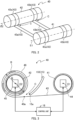
- the banknote storage unit 40 will be described with reference to FIG. 2 and FIG. 3 . Note that some of the components illustrated in FIG. 3 , such as the control unit 18, are not illustrated in FIG. 2 .
- the banknote storage units 40 are each provided inside the temporary storage unit 17 and the winding-type storage units 23.
- the banknote storage unit 40 is configured to store banknotes transported by the transport unit 15 and feed out the stored banknotes to the transport unit 15.
- the banknote storage unit 40 comprises a reel 41, a drum 42, a pair of tapes 43a and 43b, and drive units 44 and 45.
- the pair of tapes 43a and 43b is collectively referred to as a tape 43 as necessary.
- the control unit 18 controls the drive units 44 and 45, and stores banknotes in the banknote storage unit 40.
- the operations of the banknote storage unit 40 may be controlled by a controller other than the control unit 18.
- the controller may be a single controller or a plurality of controllers. In a case of a plurality of controllers, the banknote storage units 40 may be respectively controlled by different controllers.
- the reel 41 rotates around a rotation axis E1 by the operation of the drive unit 44 controlled by the control unit 18.
- the reel 41 is connected to a first end of the tape 43, and the first end side of the tape 43 is wound around the reel 41.
- the drum 42 is provided so that a rotation axis E2 of the drum 42 is parallel to the rotation axis E1 of the reel 41.
- the drum 42 rotates around the rotation axis E2 by the operation of the drive unit 45 controlled by the control unit 18.
- the drum 42 is connected to a second end of the tape 43, and the second end side of the tape 43 is wound around the drum 42.
- the tape 43 is stretched between the reel 41 and the drum 42 under tension.
- the drive unit 44 is, for example, a stepper motor.
- the drive unit 45 is, for example, a stepper motor.
- the rotation of the reel 41 and the drum 42 when a banknote is being stored in the banknote storage unit 40 is referred to as forward rotation.
- the reel 41, the drum 42, and the tape 43 are arranged as illustrated in FIG. 3
- the reel 41 and the drum 42 rotate in the same direction (clockwise direction in FIG. 3 ).
- the tape 43 pulled out from the reel 41 is wound around the drum 42 together with a banknote B passed from the transport unit 15.
- the drum 42 includes a winding body 46 together with the wound tape 43 and the wound banknote B.
- the reference sign D in FIG. 3 indicates a diameter of the winding body 46.
- the moving speed of the tape 43 on the outer circumferential surface of the winding body 46 is equal to the moving speed of the tape 43 between the reel 41 and the drum 42.
- the moving speed of the tape 43 between the reel 41 and the drum 42 or the moving speed of the tape 43 on the outer circumferential surface of the winding body 46 may be simply referred to as the moving speed of the tape 43.
- the banknote B passed from the transport unit 15 is inserted, as indicated by arrows C in FIGS. 2 and 3 , between a part of the tape 43 positioned at the outermost circumference of the winding body 46 and another part of the tape 43 stretched between the reel 41 and the drum 42.
- the inserted banknote B is wound around the drum 42 together with the tape 43 by the rotation of the drum 42.
- the point indicated by the reference sign 15a in FIG. 3 is a transport-unit-side working point, which is a point closest to the winding-type storage unit 23 (that is, the banknote storage unit 40) in a section where the fifth divergent path 155 (the transport unit 15) exerts a force to the banknote B.
- the point indicated by the reference sign 40a in FIG. 3 is a storage-unit-side working point, which is a point closest to the transport unit 15 in a section where the winding-type storage unit 23 exerts a force to the banknote B. That is, the banknote B that has made contact with the storage-unit-side working point 40a is wound into the winding body 46 by the tape 43.
- a part of the transport unit 15 including the transport-unit-side working point 15a may be placed inside the winding-type storage unit 23.
- the part of the transport unit 15 may also be configured to be separable from the main body of the transport unit 15 and integrated with the winding-type storage unit 23.
- the reel 41 and the drum 42 rotate in a direction opposite to the forward rotation. Such rotation is referred to as reverse rotation in the following.
- the reel 41, the drum 42, and the tape 43 are arranged as illustrated in FIG. 3 , the reel 41 and the drum 42 rotate in a counterclockwise direction. At this time, the tape 43 pulled out from the drum 42 is wound around the reel 41.
- the banknote B is passed to the transport unit 15.
- the banknote B that has been wound around the drum 42 is released from a state of being caught between a part of the tape 43 and another part of the tape 43.
- the banknote B is transferred in a direction opposite to the direction indicated by the arrows C, and passed to the transport unit 15.
- the control unit 18 can change the moving speed of the tape 43 by controlling the drive units 44 and 45 according to the state of the banknote storage unit 40 or the banknote processing apparatus 1.
- the moving speed of the tape 43 is the moving speed of the banknote B in the banknote storage unit 40.
- the moving speed of the tape 43 when the banknote B is being wound up is the winding speed for the banknote B
- the moving speed of the tape 43 when the banknote B is being fed out is the feeding speed for the banknote B.
- the control unit 18 can change the tension acting on the tape 43 stretched between the reel 41 and the drum 42 by controlling at least one of the drive units 44 and 45 according to the state of the banknote storage unit 40 or the banknote processing apparatus 1.
- the tension acting on the tape 43 can be adjusted by adjusting any one or more of the rotation direction, rotation speed, and torque of the reel 41, and the rotation direction, rotation speed, and torque of the drum 42.
- the control unit 18 can control the rotation speed and torque of the reel 41 and the drum 42 by controlling the rotation speed and torque of the drive units 44 and 45 using Pulse Width Modulation (PWM), for example.
- PWM Pulse Width Modulation
- banknotes are stored in the winding-type storage unit 23 in the following manner, for example.
- the transport unit 15 continuously transports the received banknotes at a predetermined transport speed.
- the banknotes are passed to the transport unit 15 at an approximately constant pace, so that the distance (interval) between the leading edge of a banknote moving on the transport unit 15 and the leading edge of the following banknote is approximately equal.
- the distance (interval) between the tailing edge of a banknote moving on the transport unit 15 and the leading edge of the following banknote is approximately equal.
- the distance between the tailing edge of a banknote moving on the transport unit 15 and the leading edge of the following banknote is sometimes referred to as an interval between banknotes.
- the distance between the tailing edge of a banknote transported by the tape 43 and the leading edge of the following banknote is sometimes referred to as an interval between banknotes.
- the interval between banknotes is determined in advance. When the interval is shorter than the predetermined interval, the recognition unit 16 no longer recognizes each banknote. In this case, the banknote is determined to be, for example, in a multi-feed state or to be a single sheet having a non-standard size, and the banknote that has been transported at a shorter interval is rejected.
- the banknotes transported by the transport unit 15 are recognized in the recognition unit 16.
- the destinations of the banknotes are determined based on the recognition results. The description continues assuming that all the banknotes are transported to a single winding-type storage unit 23.
- FIGS. 4A and 4B are conceptual diagrams for describing transfer of banknotes between the transport unit 15 and the winding-type storage unit 23 (that is, the banknote storage unit 40). Note that the shapes and layouts do not necessarily match those of the actual apparatus since they are conceptual diagrams.
- a banknote B is transported on the fifth divergent path 155 of the transport unit 15 at a speed s1.
- the banknote B is passed from the fifth divergent path 155 to the banknote storage unit 40, which is specifically the tape 43, provided in the winding-type storage unit 23.
- the banknote B is transported on the tape 43 at the speed s1, which is equal to the speed of the banknote B transported by the transport unit 15.
- This speed s1 is the moving speed of the tape 43 and is also the winding speed for the banknote B.
- the distance g is the distance between the transport-unit-side working point 15a, which is a point closest to the winding-type storage unit 23 (that is, the banknote storage unit 40) in a section where the fifth divergent path 155 exerts a force to the banknote B, and the storage-unit-side working point 40a, which is a point closest to the transport unit 15 in a section where the winding-type storage unit 23 exerts a force to the banknote B, and the distance g is shorter than the length L of the banknote B in the transport direction.
- the distance g is configured to be shorter than the transport-direction length of a banknote B having the shortest length L in the transport direction among the plurality of types of banknotes B. This configuration enables reliable transfer for all the banknotes B to be processed.
- the interval between the banknotes B being transported by the transport unit 15 is represented by d1.
- the transport speed for the banknotes B by the transport unit 15 and the moving speed of the banknotes B by the tape 43 are both s1.
- the interval between the banknotes B does not change before and after the transfer. That is, the interval between the banknotes B being transported by the tape 43 remains at d1.
- the banknotes B are wound around the winding body 46, that is, stored in the winding-type storage unit 23, while keeping the interval d1 between the banknotes B being transported by the transport unit 15.
- the difference from the case illustrated in FIG. 4A is that the moving speed of the tape 43 is not constant at s1 but down to s2 from s1 and back to s1.
- the moving speed of the tape 43 is decelerated from s1 to s2, and then accelerated from s2 to return to s1 again.
- the banknote B N After the tailing edge of the Nth banknote B N in the transport direction leaves the transport-unit-side working point 15a, the banknote B N receives force from only the tape 43. Thus, no compression force (force to bend) nor tension (force to tear off) acts on the banknote B even when the moving speed of the tape 43 is different from the transport speed s1 of the transport unit 15.
- the moving speed of the tape 43 remains slower than the transport speed s1 of the transport unit 15, however, the moving speed acting on the leading-edge side of the banknote B N+1 and the moving speed acting on the tailing-edge side of the banknote B N+1 would be different from each other when the leading edge of the banknote B N+1 in the transport direction reaches the storage-unit-side working point 40a.
- Such a situation causes compression force on the banknote B N+1 and the banknote B N+1 is bent accordingly. This possibly leads to a problem such as a jammed banknote between the transport unit 15 and the winding-type storage unit 23.
- the moving speed of the tape 43 is returned to s1 by the time when the leading edge of the banknote B N+1 in the transport direction reaches the storage-unit-side working point 40a.
- This causes force on both the leading-edge side and the tailing-edge side of the banknote B N+1 to move at the speed s1 when the leading edge of the banknote B N+1 in the transport direction reaches the storage-unit-side working point 40a.
- the banknote B N+1 is smoothly passed to and stored in the winding-type storage unit 23.
- the interval between the banknote B N and the banknote B N+1 becomes d2, which is shorter than d1.
- the interval between the banknotes can be shorter by reducing the moving speed of the tape 43 and returning to the original speed after the tailing edge of the Nth banknote B N in the transport direction leaves the transport-unit-side working point 15a and before the leading edge of the N+1th banknote B N+1 in the transport direction reaches the storage-unit-side working point 40a. Besides, it is possible to increase the number of the banknotes B to be stored in the winding-type storage unit 23.
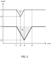
- FIG. 5 The broken line illustrated on the upper side of FIG. 5 indicates a time chart for the case that has been described with reference to FIG. 4B . This time chart will be described first.
- the tailing edge of the banknote B N in the transport direction leaves the transport-unit-side working point 15a.
- the tape 43 starts to decelerate, that is, the winding speed starts to be reduced.
- the tape 43 and the banknote B N decelerate at a predetermined deceleration rate.
- the tape 43 stops the deceleration.
- the speed of the tape 43 and the banknote B N at this time is s2.
- the tape 43 starts to accelerate.
- the tape 43 and the banknote B N accelerate at a predetermined acceleration rate.
- the speed of the tape 43 and the banknote B N reaches s1.
- the tape 43 stops the acceleration.
- the leading edge of the banknote B N+1 in the transport direction reaches the storage-unit-side working point 40a, and starts to be transported by the transport unit 15 and the tape 43.
- the area of the zone indicated by A1 corresponds to the shortened amount of the interval between the banknote B N and the banknote B N+1 (that is, the difference between d1 and d2).
- the time t2 is determined based on the deceleration rate and the acceleration rate of the tape 43, and the difference between the time t3 and the time t1.
- the speed s2 is a target speed determined based on the time reserved for deceleration (t2 - 11), the time reserved for acceleration (t3 - 12), the deceleration rate, and the acceleration rate.
- the sum of the time reserved for deceleration and the time reserved for acceleration is automatically determined by the transport speed s1 in the transport unit 15 and the interval d1 between the banknotes B.
- the time reserved for deceleration and the time reserved for acceleration are each determined by the absolute values of the deceleration rate and the acceleration rate.
- the speed s2, which is a target speed is determined depending on the deceleration rate and the acceleration rate, and can be achieved by adjusting the deceleration rate and the acceleration rate.
- the transport speed of the transport unit 15 and the moving speed of the tape 43 which is the winding speed of the winding body 46, can be reduced in the present embodiment.
- the solid line illustrated on the lower side of FIG. 5 indicates a time chart for the case where the transport speed of the transport unit 15 is reduced.
- FIG. 5 illustrates a case where the speed s3 is half the speed s1 although it is not limited to this.
- the tailing edge of the banknote B N in the transport direction leaves the transport-unit-side working point 15a.
- the tape 43 starts to decelerate, that is, the winding speed starts to be reduced. In other words, deceleration of the winding speed toward a target speed is started.
- the tape 43 and the banknote B N decelerate at a predetermined deceleration rate.
- the deceleration rate at this time may be equal to or different from the deceleration rate in the case where the transport speed of the transport unit 15 is not reduced (the case of the broken line in FIG. 5).
- FIG. 5 illustrates a case where both the deceleration rates are equal.
- the tape 43 stops the deceleration.
- the speed of the tape 43 and the banknote B N at this time is s4.
- the tape 43 starts to accelerate.
- the tape 43 and the banknote B N accelerate at a predetermined acceleration rate.
- the acceleration rate at this time may be equal to or different from the acceleration rate in the case where the transport speed of the transport unit 15 is not reduced (the case of the broken line in FIG. 5).
- FIG. 5 illustrates a case where both the acceleration rates are equal.
- the speed of the tape 43 and the banknote B N reaches s3.
- the tape 43 stops the acceleration.
- the leading edge of the banknote B N+1 in the transport direction reaches the storage-unit-side working point 40a, and starts to be transported by the transport unit 15 and the tape 43.
- the area of the zone indicated by A2 corresponds to the shortened amount of the interval between the banknote B N and the banknote B N+1 (that is, the difference between d1 and d2) in the case where the transport speed of the transport unit 15 is reduced.
- the speed s4 is a target speed determined based on the time reserved for deceleration (t3 - 11), the time reserved for acceleration (t4 - 13), the deceleration rate, and the acceleration rate.
- the sum of the time reserved for deceleration and the time reserved for acceleration is automatically determined by the transport speed s3 in the transport unit 15 and the interval d1 between the banknotes B.
- the time reserved for deceleration and the time reserved for acceleration are each determined by the absolute values of the deceleration rate and the acceleration rate.
- the speed s4, which is a target speed is determined depending on the deceleration rate and the acceleration rate, and can be achieved by adjusting the deceleration rate and the acceleration rate.
- the area of the zone A2 is larger than the area of the zone A1. That is, the interval between banknotes B can be further shortened by reducing the transport speed of the transport unit 15. The following is the reason why the area of the zone A2 is larger than the area of the zone A1.
- the reduction of the transport speed for banknotes transported by the transport unit 15 shortens the interval between banknotes B to be stored in the winding-type storage unit 23, and further, increases the number of the banknotes B to be stored in the winding-type storage unit 23.
- the deceleration rates and the acceleration rates are assumed to be equal between the cases where the transport speed is s1 and s3.
- the inertial force of the winding body 46 is less in the case where the transport speed is s3 than that in the case where the transport speed is s1 since s3 is less than s1.
- the absolute values of the deceleration rate and the acceleration rate are set greater than those in the case where the transport speed is s1. That is, the transport speed can reach the target speed s4 more quickly and can return to the original speed s3 more quickly.
- Such an operation makes the value of the target speed s4 less than the value illustrated in FIG.
- the shortened amount of the interval between the banknote B N and the banknote B N+1 increases as the target speed s4 decreases.
- the target speed s4 can be set to 0.
- rotation of the winding body 46 may be stopped for a predetermined time in addition to setting the target speed s4 to 0.
- the shape of a zone corresponding to the zone A2 is a trapezoid, the area of the zone is even larger, and the shortened amount of the interval between the banknote B N and the banknote B N+1 increases even more.
- FIG. 6 is a time chart illustrating the moving speed of the banknote B N in the case where banknotes B are intermittently stored in the winding-type storage unit 23.
- the broken lines indicate a time chart for the case where the transport speed for the banknote is s1, which is a relatively fast speed.
- the solid lines indicate a time chart for the case where the transport speed for the banknote is s3, which is slower than s1.
- the control unit 18 stops the drive unit 45.
- the winding body 46 is configured by the drum 42, the tape 43, and banknotes N that have been wound thereon, and has a certain mass.
- the winding body 46 rotates to some extent due to inertial force, accordingly.
- the winding body 46 actually stops at the time t7, and the banknote B N is moved to some extent by the tape 43 between the time t5 and the time t7.
- the amount of the movement corresponds to the area of the triangle zone indicated by A3 in FIG. 6 .
- the moving speed of the tape 43 needs to reach s1 by the time when the leading edge of the following banknote B N+1 in the transport direction reaches the storage-unit-side working point 40a.
- the winding body 46 has a certain mass, however, as described above, and the rotation speed of the winding body 46, which is the moving speed of the tape 43, does not reach s1 immediately after the drive unit 45 starts to drive.
- the tape 43 needs to start moving at the time t8, which is some time earlier than the time t10.
- the amount of the movement corresponds to the area of the triangle zone indicated by A4 in FIG. 6 .
- the operation control for the drum 42 causes the tape 43 to move a predetermined distance, which corresponds to the sum of the area of the zone A3 and the area of the zone A4, between the time t5 and the time t10.
- the time t5 is the timing at which the tailing edge of the banknote B N is about to reach the transport-unit-side working point 15a and the moving speed of the tape 43 starts to reduce from s1. That is, the time t5 is a timing for the drive unit 45 to stop.
- the time t10 is the timing at which the leading edge of the banknote B N+1 is about to reach the storage-unit-side working point 40a and the speed of the tape 43 is back to s1.
- the operation of the transport unit 15 causes transportation of the banknote B N+1 between the time t5 and the time t10.
- the leading edge of the banknote B N+1 is positioned on the upstream side, that is, the reel 41 side, in the transport direction from the storage-unit-side working point 40a.
- the distance between the leading edge of the banknote B N+1 and the transport-unit-side working point 15a, which is the length of the banknote B N+1 sticking out from the transport-unit-side working point 15a to the drum 42 side, at the time t10 is represented by X.
- the operation control for the transport unit 15 and the drum 42 may be changed as appropriate as long as the condition is satisfied where the moving speed of the tape 43 reaches s1 by the time when the leading edge of the banknote B N+1 , which follows the banknote B N , in the transport direction reaches the storage-unit-side working point 40a.
- the interval d2 between the banknotes B stored in the winding-type storage unit 23 is determined as follows, according to 1 and 2 described above.
- Interval d 2 between banknotes B Area of zone A 3 + Area of zone A 4 ⁇ Distance X between the leading edge of a following banknote B N + 1 and the transport-unit-side working point 15 a at the time when the moving speed of the tape 43 is returned to s 1 , which is the same as the transport speed s 1 of the transport unit 15
- FIG. 6 illustrates a case where the speed s3 is half the speed s1 although it is not limited to this.
- the control unit 18 stops the drive unit 45.
- the winding body 46 has a certain mass as described above; accordingly, the winding body 46 rotates to some extent due to inertial force.
- the winding body 46 actually stops (the winding speed becomes 0) at the time t6, and the banknote B N is moved to some extent by the tape 43 between the time t5 and the time t6.
- the amount of the movement corresponds to the area of the zone indicated by A5 in FIG. 6 .
- the moving speed of the tape 43 needs to reach s3 by the time when the leading edge of the following banknote B N+1 in the transport direction reaches the storage-unit-side working point 40a.
- the winding body 46 has a certain mass, however, as described above, and the rotation speed of the winding body 46, which is the moving speed of the tape 43, does not reach s3 immediately after the drive unit 45 starts to drive.
- the tape 43 needs to start moving at the time t9, which is some time earlier than the time t10.
- the amount of the movement corresponds to the area of the zone indicated by A6 in FIG. 6 .
- the sum of the area of the zone A5 and the area of the zone A6 is smaller than the sum of the area of the zone A3 and the area of the zone A4. That is, the interval between banknotes B can be shortened by reducing the transport speed of the transport unit 15 even in the case where the banknotes B are intermittently transported. Further, the reduction of the transport speed increases the number of the banknotes B to be stored in the winding-type storage unit 23.
- the deceleration rates and the acceleration rates are assumed to be equal between the cases where the transport speed is s1 and s3.
- the inertial force of the winding body 46 is less in the case where the transport speed is s3 than that in the case where the transport speed is s1 since s3 is less than s1.
- the absolute values of the deceleration rate and the acceleration rate are set greater than those in the case where the transport speed is s1. That is, the winding body 46 can be stopped more quickly and the speed can return to the speed s3 more quickly.
- Such an operation makes the sum of the area of the zone A5 and the area of the zone A6 smaller than the sum of the areas illustrated in FIG. 6 , thereby increasing the shortened amount of the interval between the banknote B N and the banknote B N+1 . It is thus possible to increase the number of the banknotes B to be stored in the winding-type storage unit 23.
- the temporary storage unit 17 comprising the banknote storage unit 40 can also increase the number of the banknotes B to be stored in the same manner as the winding-type storage unit 23.
- the pattern 1 is control of moving banknotes stored in one of the winding-type storage units 23 to the temporary storage unit 17, temporarily storing the banknotes in the temporary storage unit 17, and moving the banknotes back in the original winding-type storage unit 23, in order to increase the number of the banknotes stored in the one of the winding-type storage units 23.
- the one of the winding-type storage units 23 is referred to as a "first storage unit”
- the temporary storage unit 17 is referred to as a "second storage unit” in the present pattern.
- This control can be performed when the first storage unit is in a predetermined state.
- the first example of the predetermined state is that the number of banknotes stored in the first storage unit reaches a predetermined value.
- the control unit 18 can count the number of banknotes stored in the first storage unit based on signals from a sensor that is comprised in the first storage unit and detects passage of banknotes.
- the second example of the predetermined state is that the diameter of the winding body 46 reaches a predetermined value.
- the control unit 18 can calculate the diameter of the winding body 46 based on the number of steps of each stepper motor in a case where the drive units 44 and 45 are stepper motors.
- the third example of the predetermined state is that the interval between banknotes wound around the drum 42, i.e., the winding body 46, satisfies a predetermined condition.
- the predetermined condition may be, for example, that the mean value of the intervals between the wound banknotes reaches a predetermined threshold.
- the predetermined condition may also be that the degree of variability of the intervals between the wound banknotes reaches a predetermined threshold.
- the control unit 18 can obtain information on the interval between the banknotes by calculating the interval between the banknotes based on the number of steps of each stepper motor in a case where the drive units 44 and 45 are stepper motors.
- the control unit 18 controls the first storage unit, the second storage unit, and the transport unit 15 to increase the number of stored banknotes.
- the banknotes stored in the first storage unit before the control to increase the number of stored banknotes are, for example, banknotes that are deposited from the inlet 12, recognized by the recognition unit 16, temporarily stored in the second storage unit, and stored in the first storage unit.
- Those banknotes are banknotes that have been stored in the first storage unit according to the time chart indicated by the broken line in FIG. 5 . That is, before the control to increase the number of stored banknotes, the transport speed for banknotes by the transport unit 15 is relatively fast; accordingly, the banknote processing apparatus 1 can process a large amount of banknotes quickly.
- the transport unit 15 transports the banknotes stored in the first storage unit to the second storage unit at a first transport speed.
- the first transport speed may be the speed s1 illustrated in FIG. 5 . This operation enables quick movement of the banknotes.
- the transport unit 15 Under the control of the control unit 18, the transport unit 15 then transports the banknotes stored in the second storage unit to the first storage unit at a second transport speed.
- the second transport speed is slower than the first transport speed.
- the second transport speed may be the speed s3 illustrated in FIG. 5 .
- the first storage unit (drive units 44 and 45 in particular) stores the banknotes while increasing and reducing the winding speed according to the time chart indicated by the solid line in FIG. 5 . That is, the control unit 18 controls the first storage unit so that the winding speed is a first winding speed that is slower than the second transport speed.
- the first winding speed may be the speed s4 illustrated in FIG. 5 .
- Such control shortens the interval between the banknotes stored in the first storage unit, thus increasing the number of banknotes stored in the first storage unit.
- control to increase the number of banknotes is preferentially performed when the operating rate of the banknote processing apparatus 1 is low (e.g., at night) since the second transport speed is slower than the first transport speed.
- control unit 18 may obtain time information, and perform the above-described control based on the time information, e.g., after business hours of a store where the banknote processing apparatus 1 is installed.
- control in the pattern 1 may be performed together with so called reconciliation processing. That is, the banknotes stored in the first storage unit may be transported to the recognition unit 16 and recognized by the recognition unit 16 before being transported to the second storage unit.
- the pattern 2 is control of moving banknotes stored in one of the winding-type storage units 23 to a different one of the winding-type storage units 23, temporarily storing the banknotes in the different one of the winding-type storage units 23, and moving the banknotes back in the original winding-type storage unit 23, in order to increase the number of the banknotes B stored in the one of the winding-type storage units 23.
- the winding-type storage unit 23 that originally and eventually stores the banknotes is referred to as a "first storage unit”
- the winding-type storage units 23 that temporarily stores the banknotes is referred to as a "second storage unit" in the present pattern.
- the control in the pattern 2 is the same as the control in the pattern 1 except that the second storage unit is changed from the temporary storage unit 17 to one of the winding-type storage units 23.
- the control in the pattern 2 shortens the interval between the banknotes stored in the first storage unit, thereby increasing the number of banknotes stored in the first storage unit.
- control in the pattern 2 can be performed without feeding out banknotes from the storage 20, that is, without feeding out from the safe. This eliminates the risk of a banknote getting jammed when moving back and forth between the storage 20 and the processing unit 10. In addition, the inside of the storage 20 cannot be accessed from the outside unless the lockable door is unlocked. Thus, it is possible to move banknotes while reducing the probability of unexpected events.
- the banknote moved from the first storage unit to the second storage unit need not be immediately moved back to the first storage unit.
- the banknote may be moved back from the second storage unit to the first storage unit when the interval between the banknotes stored in the second storage unit satisfies a predetermined condition after the banknote is moved from the first storage unit to the second storage unit.
- the predetermined condition may be, for example, that the mean value of the intervals between the wound banknotes reaches a predetermined threshold.
- the predetermined condition may also be that the degree of variability of the intervals between the wound banknotes reaches a predetermined threshold.
- the control unit 18 can obtain information on the interval between the banknotes by calculating the interval between the banknotes based on the number of steps of each stepper motor in a case where the drive units 44 and 45 of the banknote storage unit 40 comprised in the temporary storage unit 17, which is the second storage unit, are stepper motors.
- the pattern 3 is control of moving banknotes stored in one of the winding-type storage units 23 to the temporary storage unit 17, temporarily storing the banknotes in the temporary storage unit 17, and moving the banknotes back in the original winding-type storage unit 23, in order to increase the number of the banknotes stored in the one of the winding-type storage units 23.
- the one of the winding-type storage units 23 is referred to as a "first storage unit”
- the temporary storage unit 17 is referred to as a "second storage unit" in the present pattern.
- control in the pattern 3 the transport speed and the winding speed are reduced when the banknotes are moved from the first storage unit to the second storage unit and temporarily stored as well as when the banknotes are moved back from the second storage unit to the first storage unit.
- the control in the pattern 3 is the same as the control in the pattern 1 otherwise.
- control is specifically performed as follows.
- control unit 18 controls the first storage unit, the second storage unit, and the transport unit 15 to increase the number of stored banknotes.
- the transport unit 15 transports the banknotes stored in the first storage unit to the second storage unit at a first transport speed.
- the first transport speed may be the speed s3 illustrated in FIG. 5 . That is, the transport speed for the banknotes is already slower than usual at this stage.
- the second storage unit (more specifically, the drive units 44 and 45 of the banknote storage unit 40 comprised in the temporary storage unit 17) stores the banknotes while increasing and reducing the winding speed according to the time chart indicated by the solid line in FIG. 5 . That is, the control unit 18 controls the second storage unit so that the winding speed is a second winding speed that is slower than the first transport speed.
- the second winding speed may be the speed s4 illustrated in FIG. 5 .
- the interval between the banknotes stored in the second storage unit is shorter than the interval when the banknotes were previously stored in the first storage unit.
- the transport unit 15 transports the banknotes stored in the second storage unit to the first storage unit at a second transport speed.
- the second transport speed is slower than the first transport speed.
- the second transport speed may be slower than the speed s3 illustrated in FIG. 5 .
- the first storage unit (drive units 44 and 45 in particular) stores the banknotes while increasing and reducing the winding speed. That is, the control unit 18 controls the first storage unit so that the winding speed is a first winding speed that is slower than the second transport speed. The first winding speed is slower than the second winding speed.
- the interval between the banknotes is even shorter than the interval when the banknotes were previously stored in the second storage unit. That is, such control further shortens the interval between the banknotes stored in the first storage unit, thus further increasing the number of banknotes stored in the first storage unit.
- the pattern 4 is control of moving banknotes stored in one of the winding-type storage units 23 to a different one of the winding-type storage units 23, temporarily storing the banknotes in the different one of the winding-type storage units 23, and moving the banknotes back in the original winding-type storage unit 23, in order to increase the number of the banknotes stored in the one of the winding-type storage units 23.
- the winding-type storage units 23 that originally and eventually stores the banknotes is referred to as a "first storage unit”
- the winding-type storage units 23 that temporarily stores the banknotes is referred to as a "second storage unit" in the present pattern.
- each unit is controlled so that the winding speed is reduced when the banknotes are moved from the first storage unit to the second storage unit and temporarily stored as well as when the banknotes are moved back from the second storage unit to the first storage unit.
- This operation is common to the pattern 3 and different from the pattern 2.
- the control in the pattern 4 is the same as the control in the pattern 2 otherwise.
- control in the pattern 4 further shortens the interval between the banknotes stored in the first storage unit, thereby further increasing the number of banknotes stored in the first storage unit.
- control in the pattern 4 can be performed without feeding out banknotes from the storage 20, that is, without feeding out from the safe. This eliminates the risk of a banknote getting jammed when moving back and forth between the storage 20 and the processing unit 10. Further, the inside of the storage 20 cannot be accessed from the outside unless the lockable door is unlocked. Thus, it is possible to move banknotes while reducing the probability of unexpected events.
- the pattern 5 is control performed at the time of so called deposit processing.
- the pattern 5 is control for storing as many banknotes as possible in one of the winding-type storage units 23 from the beginning.
- the one of the winding-type storage units 23 is referred to as a "first storage unit”
- the temporary storage unit 17 is referred to as a "second storage unit” in the present pattern.
- the control in the pattern 5 is performed as follows. First, banknotes deposited from the inlet 12 are transported to the recognition unit 16 by the transport unit 15 and recognized, under the control of the control unit 18. The banknotes are then transported to the second storage unit and temporarily stored. During the operation, the transport unit 15 transports the banknotes at a first transport speed.
- the first transport speed may be the speed s1 illustrated in FIG. 5 .
- the transport unit 15 Under the control of the control unit 18, the transport unit 15 then transports the banknotes stored in the second storage unit to the first storage unit at a second transport speed.
- the second transport speed is slower than the first transport speed.
- the second transport speed may be the speed s3 illustrated in FIG. 5 .
- the first storage unit (drive units 44 and 45 in particular) stores the banknotes while increasing and reducing the winding speed according to the time chart indicated by the solid line in FIG. 5 . That is, the control unit 18 controls the first storage unit so that the winding speed is a first winding speed that is slower than the second transport speed.
- the first winding speed may be the speed s4 illustrated in FIG. 5 .
- Such control makes it possible to store the banknotes in the first storage unit with shortened intervals from the beginning, thus increasing the number of banknotes stored in the first storage unit.
- the transport speed to transport the banknotes to the second storage unit can be set to the first transport speed, which is a relatively fast speed. This minimizes the increase in processing time required for deposit processing.
- the second transport speed is slower than the first transport speed; accordingly, the banknote processing apparatus 1 makes less noise when the transport unit 15 moves at the second transport speed than when the transport unit 15 moves at the first transport speed.
- the control described above may be actively performed as a so-called silent mode during business hours of a store.
- the banknote processing apparatus 1 can also extend the interval between banknotes to be stored in the first storage unit.
- the interval between banknotes stored in the first storage unit can be extended by, for example, not reducing but increasing the rotation speed of the winding body 46 (more specifically, accelerating and then decelerating to the original speed) when the banknotes are being stored in the first storage unit. That is, the banknote processing apparatus 1 can either shorten or extend the interval between banknotes to be stored in the first storage unit. In other words, the banknote processing apparatus 1 can adjust the interval between banknotes to be stored in the first storage unit to an appropriate length. At this time, the accuracy of the interval between banknotes can be improved by reducing the speed to transport banknotes to the first storage unit by the transport unit 15.
- the banknote processing apparatus 1 can easily determine a group of banknotes for a single transaction by extending the interval between a group of banknotes and another group of banknotes to be processed.
- arrangement positions of banknotes in the winding body 46 can be adjusted by appropriately adjusting the interval between the banknotes. This makes it easy to maintain the shape of a cut surface of a plane perpendicular to the rotation axis E2 (see FIGS. 2 and 3 ) of the winding body 46 in a circular shape.
- the first storage unit may be a storage unit that can be detachably attached to the banknote processing apparatus 1.
- the first storage unit may be a storage unit to be attached to the banknote processing apparatus 1 after banknotes are stored in the first storage unit by an apparatus other than the banknote processing apparatus 1.
- banknotes stored in the first storage unit are temporarily moved to the second storage unit, which is the temporary storage unit 17 or the winding-type storage unit 23, and then moved bank in the first storage unit, thereby shortening the interval between the banknotes, i.e., increasing the amount of banknotes to be stored in the first storage unit.
- the present disclosure is suitable for a sheet processing apparatus that processes sheets such as banknotes.
Landscapes
- Physics & Mathematics (AREA)
- General Physics & Mathematics (AREA)
- Engineering & Computer Science (AREA)
- Mechanical Engineering (AREA)
- Discharge By Other Means (AREA)
- Controlling Sheets Or Webs (AREA)
Claims (15)
- Bogenverarbeitungsvorrichtung (1) umfassend:eine erste Speichereinheit (23), bei der es sich um eine Speichereinheit vom Windungstyp handelt, bei der ein Bogen zusammen mit einem Band (43) um eine Trommel (42) gewunden und gespeichert wird; undeine zweite Speichereinheit (17), die den Bogen speichert;dadurch gekennzeichnet, dass die Bogenverarbeitungsvorrichtung (1) weiterhin umfasst:
eine Transporteinheit (15), die den Bogen mit einer ersten Transportgeschwindigkeit zu der zweiten Speichereinheit (17) und mit einer zweiten Transportgeschwindigkeit von der zweiten Speichereinheit (17) zu der ersten Speichereinheit (23) transportiert; undeine Steuereinheit (18), die die erste Speichereinheit (23), die zweite Speichereinheit (17) und die Transporteinheit (15) so steuert, dass die zweite Transportgeschwindigkeit langsamer ist als die erste Transportgeschwindigkeit und eine Windungsgeschwindigkeit zum Aufwinden des Bogens durch die erste Speichereinheit (23) eine erste Windungsgeschwindigkeit ist, die langsamer ist als die zweite Transportgeschwindigkeit. - Bogenverarbeitungsvorrichtung (1) nach Anspruch 1, bei der die Steuereinheit (18) die erste Speichereinheit (23), die zweite Speichereinheit (17) und die Transporteinheit (15) steuert, wenn eine Anzahl einer Vielzahl der in der ersten Speichereinheit (23) gespeicherten Bögen größer oder gleich einem vorbestimmten Wert ist, so dass die Vielzahl der in der ersten Speichereinheit (23) gespeicherten Bögen vorübergehend in der zweiten Speichereinheit (17) gespeichert und dann zur ersten Speichereinheit (23) zurückgeführt werden.
- Bogenverarbeitungsvorrichtung (1) nach Anspruch 1, bei der, wenn ein Durchmesser eines Windungskörpers (46), der den Bogen, das Band (43) und die Trommel (42) enthält, größer oder gleich einem vorbestimmten Wert ist, die Steuereinheit (18) die erste Speichereinheit (23), die zweite Speichereinheit (17) und die Transporteinheit (15) so steuert, dass der in der ersten Speichereinheit (23) gespeicherte Bogen vorübergehend in der zweiten Speichereinheit (17) gespeichert und dann zur ersten Speichereinheit (23) zurückgeführt wird.
- Bogenverarbeitungsvorrichtung (1) nach Anspruch 1, bei der die Steuereinheit (18) auf der Grundlage von Informationen über einen Abstand zwischen einer Vielzahl von um die Trommel (42) in der ersten Speichereinheit (23) gewundenen Bögen die erste Speichereinheit (23), die zweite Speichereinheit (17) und die Transporteinheit (15) so steuert, dass die Vielzahl von in der ersten Speichereinheit (23) gespeicherten Bögen vorübergehend in der zweiten Speichereinheit (17) gespeichert und dann zur ersten Speichereinheit (23) zurückgeführt wird.
- Bogenverarbeitungsvorrichtung (1) nach einem der Ansprüche 1 bis 4, bei dem die Steuereinheit (18) Zeitinformationen erfasst, und bei der die Steuereinheit (18) auf der Grundlage der Zeitinformationen die erste Speichereinheit (23), die zweite Speichereinheit (17) und die Transporteinheit (15) steuert, so dass der in der ersten Speichereinheit (23) gespeicherte Bogen vorübergehend in der zweiten Speichereinheit (17) gespeichert und dann zur ersten Speichereinheit (23) zurückgeführt wird.
- Bogenverarbeitungsvorrichtung (1) nach einem der Ansprüche 1 bis 5, die ferner eine Erkennungseinheit (16) umfasst, die das von der Transporteinheit (15) transportierte Blatt erkennt, wobei die Steuereinheit (18) die erste Speichereinheit (23), die zweite Speichereinheit (17) und die Transporteinheit (15) so steuert, dass der von der Erkennungseinheit (16) erkannte Bogen in der zweiten Speichereinheit (17) zwischengespeichert und dann in der ersten Speichereinheit (23) gespeichert wird.
- Bogenverarbeitungsvorrichtung (1) nach Anspruch 6, bei der die Steuereinheit (18) auf der Grundlage von Informationen über einen Abstand zwischen einer Vielzahl der in der zweiten Speichereinheit (17) gespeicherten Bögen die erste Speichereinheit (23), die zweite Speichereinheit (17) und die Transporteinheit (15) steuert, so dass die Vielzahl der in der zweiten Speichereinheit (17) gespeicherten Bögen von der zweiten Speichereinheit (17) zur ersten Speichereinheit (23) transportiert wird.
- Bogenverarbeitungsvorrichtung (1) nach Anspruch 6 oder 7, die ferner einen Einlass (12) umfasst, der den Bogen aufnimmt, wobei die Transporteinheit (15) den Bogen von dem Einlass (12) über die Erkennungseinheit (16) mit der ersten Transportgeschwindigkeit zu der zweiten Speichereinheit (17) transportiert.
- Bogenverarbeitungsvorrichtung (1) nach einem der Ansprüche 1 bis 5, die ferner eine Erkennungseinheit (16) umfasst, die den von der Transporteinheit (15) transportierten Bogen erkennt, wobei die Steuereinheit (18) die erste Speichereinheit (23), die zweite Speichereinheit (17) und die Transporteinheit (15) so steuert, dass der in der ersten Speichereinheit (23) gespeicherte Bogen von der Erkennungseinheit (16) erkannt und dann in der zweiten Speichereinheit (17) gespeichert wird.
- Bogenverarbeitungsvorrichtung (1) nach einem der Ansprüche 1 bis 5, bei derdie zweite Speichereinheit (17), in der der Bogen gespeichert wird, indem er zusammen mit einem Band (43) um eine Trommel (42) gewunden wird, eine Speichereinheit vom Windungstyp ist unddie Steuereinheit (18) die erste Speichereinheit (23), die zweite Speichereinheit (17) und die Transporteinheit (15) so steuert, dass der Bogen von der ersten Speichereinheit (23) zu der zweiten Speichereinheit (17) mit der ersten Transportgeschwindigkeit transportiert wird und eine zweite Windungsgeschwindigkeit zum Aufwinden des Bogens durch die zweite Speichereinheit (17) langsamer als die erste Transportgeschwindigkeit und schneller als die erste Windungsgeschwindigkeit ist.
- Bogenverarbeitungsvorrichtung (1) nach einem der Ansprüche 1 bis 10, die ferner eine verschließbare Truhe (20) umfasst, wobei die erste Speichereinheit (23) in der verschließbaren Truhe (20) angeordnet ist.
- Bogenverarbeitungsvorrichtung (1) nach Anspruch 11, bei der die zweite Speichereinheit (17) in der verschließbaren Truhe (20) untergebracht ist.
- Bogenverarbeitungsvorrichtung (1) nach einem der Ansprüche 1 bis 12, bei derdie Transporteinheit (15) einen transporteinheitsseitigen Arbeitspunkt aufweist, der der ersten Speichereinheit (23) in einem Abschnitt am nächsten liegt, in dem die Transporteinheit (15) eine Kraft auf den Bogen ausübt,die erste Speichereinheit (23) einen ersten speichereinheitsseitigen Arbeitspunkt aufweist, der der Transporteinheit (15) in einem Abschnitt am nächsten liegt, in dem die erste Speichereinheit (23) eine Kraft auf den Bogen ausübt,ein Abstand zwischen dem transportanlagenseitigen Arbeitspunkt und dem ersten lageranlagenseitigen Arbeitspunkt kürzer ist als eine Transportrichtungslänge des Bogens, unddie Steuereinheit (18) die erste Speichereinheit (23) und die Transporteinheit (15) so steuert, dass sie mit der Verlangsamung der Windungsgeschwindigkeit auf eine Zielgeschwindigkeit beginnt, wenn eine hintere Kante des von der Transporteinheit (15) zur ersten Speichereinheit (23) zu führenden Bogens in einer Bewegungsrichtung den ersten speichereinheitsseitigen Arbeitspunkt erreicht, wobei die Zielgeschwindigkeit als die erste Windungsgeschwindigkeit bezeichnet wird.
- Bogenverarbeitungsvorrichtung (1) nach Anspruch 13, bei derder Bogen einer von mehreren Typen von Bögen ist, die sich in der Länge in Transportrichtung voneinander unterscheiden; undder Abstand kürzer ist als die Länge in Transportrichtung des Bogens mit der kürzesten Länge in Transportrichtung unter den mehreren Bogensorten.
- Bogenverarbeitungsvorrichtung (1) nach Anspruch 13 oder 14, bei der die Steuereinheit (18) die erste Speichereinheit (23) und die Transporteinheit (15) so steuert, dass sie die Verlangsamung der Windungsgeschwindigkeit von der ersten Windungsgeschwindigkeit auf eine Zielgeschwindigkeit von 0 einleitet.
Applications Claiming Priority (2)
| Application Number | Priority Date | Filing Date | Title |
|---|---|---|---|
| JP2019171930A JP2021051335A (ja) | 2019-09-20 | 2019-09-20 | 紙葉類処理装置 |
| PCT/JP2020/033383 WO2021054134A1 (ja) | 2019-09-20 | 2020-09-03 | 紙葉類処理装置 |
Publications (3)
| Publication Number | Publication Date |
|---|---|
| EP4032840A1 EP4032840A1 (de) | 2022-07-27 |
| EP4032840A4 EP4032840A4 (de) | 2022-11-16 |
| EP4032840B1 true EP4032840B1 (de) | 2023-12-13 |
Family
ID=74883651
Family Applications (1)
| Application Number | Title | Priority Date | Filing Date |
|---|---|---|---|
| EP20864711.5A Active EP4032840B1 (de) | 2019-09-20 | 2020-09-03 | Papierblattverarbeitungsvorrichtung |
Country Status (4)
| Country | Link |
|---|---|
| US (1) | US20220207949A1 (de) |
| EP (1) | EP4032840B1 (de) |
| JP (1) | JP2021051335A (de) |
| WO (1) | WO2021054134A1 (de) |
Families Citing this family (3)
| Publication number | Priority date | Publication date | Assignee | Title |
|---|---|---|---|---|
| JP2021081974A (ja) * | 2019-11-19 | 2021-05-27 | グローリー株式会社 | 紙葉類処理装置 |
| JP2021144441A (ja) * | 2020-03-11 | 2021-09-24 | グローリー株式会社 | 紙葉類収納装置 |
| US20250272545A1 (en) | 2022-05-13 | 2025-08-28 | Koch Business Solutions, Lp | Time-series dimension compression |
Family Cites Families (15)
| Publication number | Priority date | Publication date | Assignee | Title |
|---|---|---|---|---|
| JP3437432B2 (ja) * | 1998-02-02 | 2003-08-18 | グローリー工業株式会社 | 紙幣入出金機 |
| CA2299827C (en) * | 2000-03-02 | 2009-12-15 | Cashcode Company Inc. | Combination banknote validator and banknote dispenser |
| US8944234B1 (en) * | 2001-09-27 | 2015-02-03 | Cummins-Allison Corp. | Apparatus and system for imaging currency bills and financial documents and method for using the same |
| JP4130887B2 (ja) * | 2002-10-03 | 2008-08-06 | 日立オムロンターミナルソリューションズ株式会社 | 紙幣収納放出装置及び紙幣搬送装置 |
| US8162308B2 (en) * | 2008-06-04 | 2012-04-24 | Glory Ltd. | Paper sheet processing device and method for controlling paper sheet processing device |
| DE102008046811A1 (de) * | 2008-09-11 | 2010-03-18 | Adp Gauselmann Gmbh | Verfahren zum Betreiben einer Transporteinrichtung mit der Banknoten von einer Banknotenprüf- und -annahmeeinheit zu einer Vorrichtung zum Speichern von Banknoten transportiert werden |
| JP2010095340A (ja) * | 2008-10-16 | 2010-04-30 | Laurel Precision Machines Co Ltd | 紙葉類収納繰出装置 |
| EP2579223B1 (de) * | 2010-06-07 | 2016-08-10 | Glory Ltd. | Vorrichtung für lagerung und vorschub von papierblättern und verfahren zur aufbewahrung von papierblättern |
| CN103080986B (zh) * | 2010-09-01 | 2016-06-01 | 光荣株式会社 | 纸张处理装置以及纸币处理装置 |
| JP2012198764A (ja) | 2011-03-22 | 2012-10-18 | Glory Ltd | 貨幣処理装置 |
| JP5976497B2 (ja) * | 2012-10-23 | 2016-08-23 | グローリー株式会社 | 紙幣処理装置及び紙幣処理装置の制御方法 |
| US9934642B2 (en) * | 2014-12-18 | 2018-04-03 | Crane Payment Innovations, Inc. | Multiclass logical document recycler management |
| JP2017016322A (ja) * | 2015-06-30 | 2017-01-19 | 日立オムロンターミナルソリューションズ株式会社 | 媒体搬送制御装置及び媒体搬送制御方法 |
| CN107949869A (zh) * | 2015-09-11 | 2018-04-20 | 光荣株式会社 | 纸张收纳输送装置 |
| JP7063047B2 (ja) | 2018-03-27 | 2022-05-09 | トヨタ自動車株式会社 | ホイールハウス部構造 |
-
2019
- 2019-09-20 JP JP2019171930A patent/JP2021051335A/ja active Pending
-
2020
- 2020-09-03 WO PCT/JP2020/033383 patent/WO2021054134A1/ja not_active Ceased
- 2020-09-03 EP EP20864711.5A patent/EP4032840B1/de active Active
-
2022
- 2022-03-17 US US17/696,882 patent/US20220207949A1/en active Pending
Also Published As
| Publication number | Publication date |
|---|---|
| EP4032840A1 (de) | 2022-07-27 |
| EP4032840A4 (de) | 2022-11-16 |
| JP2021051335A (ja) | 2021-04-01 |
| WO2021054134A1 (ja) | 2021-03-25 |
| US20220207949A1 (en) | 2022-06-30 |
Similar Documents
| Publication | Publication Date | Title |
|---|---|---|
| JP5485388B2 (ja) | 紙葉類収納操出装置、紙葉類処理装置、及び紙葉類収納方法 | |
| US8162308B2 (en) | Paper sheet processing device and method for controlling paper sheet processing device | |
| EP2259233B1 (de) | Papiernoten-handhabungsvorrichtung und verfahren zum handhaben von papiernoten | |
| US20220207949A1 (en) | Sheet processing apparatus | |
| EP3798164B1 (de) | Blattbearbeitungsmaschine und blattverarbeitungsverfahren | |
| US9183691B2 (en) | Banknote pay-in/pay-out device and banknote processing machine | |
| CN111566033B (zh) | 纸张堆积用滚筒、纸张堆积装置以及纸张处理装置 | |
| EP2189952A1 (de) | Papierblatthandhabungsmechanismus und papierblatthandhabungsverfahren | |
| US8678387B2 (en) | Paper-sheet handling apparatus and paper-sheet handling method | |
| US7900900B2 (en) | Sheet handling device and sheet handling method | |
| US12246937B2 (en) | Sheet storage unit | |
| JP7158322B2 (ja) | 紙葉類収納装置及び紙葉類収納方法 | |
| JPH08268617A (ja) | 紙葉類繰込み繰出し装置 | |
| EP3825266B1 (de) | Vorrichtung zur blatthandhabung | |
| US11148897B2 (en) | Device and method for storing value documents, in particular banknotes, and storage device and value document processing system | |
| JP2010020720A (ja) | 紙幣入出金装置 | |
| JPS6111157Y2 (de) | ||
| WO2011155018A1 (ja) | 紙葉類収納繰出装置及び紙葉類処理装置 | |
| JPH08268621A (ja) | 紙葉類搬送分岐機構 |
Legal Events
| Date | Code | Title | Description |
|---|---|---|---|
| STAA | Information on the status of an ep patent application or granted ep patent |
Free format text: STATUS: THE INTERNATIONAL PUBLICATION HAS BEEN MADE |
|
| PUAI | Public reference made under article 153(3) epc to a published international application that has entered the european phase |
Free format text: ORIGINAL CODE: 0009012 |
|
| STAA | Information on the status of an ep patent application or granted ep patent |
Free format text: STATUS: REQUEST FOR EXAMINATION WAS MADE |
|
| 17P | Request for examination filed |
Effective date: 20220316 |
|
| AK | Designated contracting states |
Kind code of ref document: A1 Designated state(s): AL AT BE BG CH CY CZ DE DK EE ES FI FR GB GR HR HU IE IS IT LI LT LU LV MC MK MT NL NO PL PT RO RS SE SI SK SM TR |
|
| REG | Reference to a national code |
Ref country code: DE Ref legal event code: R079 Free format text: PREVIOUS MAIN CLASS: B65H0043000000 Ipc: B65H0029000000 Ref country code: DE Ref legal event code: R079 Ref document number: 602020022874 Country of ref document: DE Free format text: PREVIOUS MAIN CLASS: B65H0043000000 Ipc: B65H0029000000 |
|
| A4 | Supplementary search report drawn up and despatched |
Effective date: 20221019 |
|
| RIC1 | Information provided on ipc code assigned before grant |
Ipc: B65H 43/00 20060101ALI20221013BHEP Ipc: B65H 29/00 20060101AFI20221013BHEP |
|
| DAV | Request for validation of the european patent (deleted) | ||
| DAX | Request for extension of the european patent (deleted) | ||
| GRAP | Despatch of communication of intention to grant a patent |
Free format text: ORIGINAL CODE: EPIDOSNIGR1 |
|
| STAA | Information on the status of an ep patent application or granted ep patent |
Free format text: STATUS: GRANT OF PATENT IS INTENDED |
|
| P01 | Opt-out of the competence of the unified patent court (upc) registered |
Effective date: 20230531 |
|
| RIC1 | Information provided on ipc code assigned before grant |
Ipc: G07D 11/16 20190101ALI20230615BHEP Ipc: G07D 11/12 20190101ALI20230615BHEP Ipc: G07D 11/10 20190101ALI20230615BHEP Ipc: B65H 43/00 20060101ALI20230615BHEP Ipc: B65H 29/00 20060101AFI20230615BHEP |
|
| INTG | Intention to grant announced |
Effective date: 20230711 |
|
| GRAS | Grant fee paid |
Free format text: ORIGINAL CODE: EPIDOSNIGR3 |
|
| GRAA | (expected) grant |
Free format text: ORIGINAL CODE: 0009210 |
|
| STAA | Information on the status of an ep patent application or granted ep patent |
Free format text: STATUS: THE PATENT HAS BEEN GRANTED |
|
| AK | Designated contracting states |
Kind code of ref document: B1 Designated state(s): AL AT BE BG CH CY CZ DE DK EE ES FI FR GB GR HR HU IE IS IT LI LT LU LV MC MK MT NL NO PL PT RO RS SE SI SK SM TR |
|
| REG | Reference to a national code |
Ref country code: GB Ref legal event code: FG4D |
|
| REG | Reference to a national code |
Ref country code: CH Ref legal event code: EP |
|
| REG | Reference to a national code |
Ref country code: DE Ref legal event code: R096 Ref document number: 602020022874 Country of ref document: DE |
|
| REG | Reference to a national code |
Ref country code: IE Ref legal event code: FG4D |
|
| PG25 | Lapsed in a contracting state [announced via postgrant information from national office to epo] |
Ref country code: GR Free format text: LAPSE BECAUSE OF FAILURE TO SUBMIT A TRANSLATION OF THE DESCRIPTION OR TO PAY THE FEE WITHIN THE PRESCRIBED TIME-LIMIT Effective date: 20240314 |
|
| REG | Reference to a national code |
Ref country code: LT Ref legal event code: MG9D |
|
| PG25 | Lapsed in a contracting state [announced via postgrant information from national office to epo] |
Ref country code: LT Free format text: LAPSE BECAUSE OF FAILURE TO SUBMIT A TRANSLATION OF THE DESCRIPTION OR TO PAY THE FEE WITHIN THE PRESCRIBED TIME-LIMIT Effective date: 20231213 |
|
| REG | Reference to a national code |
Ref country code: NL Ref legal event code: MP Effective date: 20231213 |
|
| PG25 | Lapsed in a contracting state [announced via postgrant information from national office to epo] |
Ref country code: ES Free format text: LAPSE BECAUSE OF FAILURE TO SUBMIT A TRANSLATION OF THE DESCRIPTION OR TO PAY THE FEE WITHIN THE PRESCRIBED TIME-LIMIT Effective date: 20231213 |
|
| PG25 | Lapsed in a contracting state [announced via postgrant information from national office to epo] |
Ref country code: LT Free format text: LAPSE BECAUSE OF FAILURE TO SUBMIT A TRANSLATION OF THE DESCRIPTION OR TO PAY THE FEE WITHIN THE PRESCRIBED TIME-LIMIT Effective date: 20231213 Ref country code: GR Free format text: LAPSE BECAUSE OF FAILURE TO SUBMIT A TRANSLATION OF THE DESCRIPTION OR TO PAY THE FEE WITHIN THE PRESCRIBED TIME-LIMIT Effective date: 20240314 Ref country code: ES Free format text: LAPSE BECAUSE OF FAILURE TO SUBMIT A TRANSLATION OF THE DESCRIPTION OR TO PAY THE FEE WITHIN THE PRESCRIBED TIME-LIMIT Effective date: 20231213 Ref country code: BG Free format text: LAPSE BECAUSE OF FAILURE TO SUBMIT A TRANSLATION OF THE DESCRIPTION OR TO PAY THE FEE WITHIN THE PRESCRIBED TIME-LIMIT Effective date: 20240313 |
|
| REG | Reference to a national code |
Ref country code: AT Ref legal event code: MK05 Ref document number: 1640300 Country of ref document: AT Kind code of ref document: T Effective date: 20231213 |
|
| PG25 | Lapsed in a contracting state [announced via postgrant information from national office to epo] |
Ref country code: NL Free format text: LAPSE BECAUSE OF FAILURE TO SUBMIT A TRANSLATION OF THE DESCRIPTION OR TO PAY THE FEE WITHIN THE PRESCRIBED TIME-LIMIT Effective date: 20231213 |
|
| PG25 | Lapsed in a contracting state [announced via postgrant information from national office to epo] |
Ref country code: SE Free format text: LAPSE BECAUSE OF FAILURE TO SUBMIT A TRANSLATION OF THE DESCRIPTION OR TO PAY THE FEE WITHIN THE PRESCRIBED TIME-LIMIT Effective date: 20231213 Ref country code: RS Free format text: LAPSE BECAUSE OF FAILURE TO SUBMIT A TRANSLATION OF THE DESCRIPTION OR TO PAY THE FEE WITHIN THE PRESCRIBED TIME-LIMIT Effective date: 20231213 Ref country code: NO Free format text: LAPSE BECAUSE OF FAILURE TO SUBMIT A TRANSLATION OF THE DESCRIPTION OR TO PAY THE FEE WITHIN THE PRESCRIBED TIME-LIMIT Effective date: 20240313 Ref country code: NL Free format text: LAPSE BECAUSE OF FAILURE TO SUBMIT A TRANSLATION OF THE DESCRIPTION OR TO PAY THE FEE WITHIN THE PRESCRIBED TIME-LIMIT Effective date: 20231213 Ref country code: LV Free format text: LAPSE BECAUSE OF FAILURE TO SUBMIT A TRANSLATION OF THE DESCRIPTION OR TO PAY THE FEE WITHIN THE PRESCRIBED TIME-LIMIT Effective date: 20231213 Ref country code: HR Free format text: LAPSE BECAUSE OF FAILURE TO SUBMIT A TRANSLATION OF THE DESCRIPTION OR TO PAY THE FEE WITHIN THE PRESCRIBED TIME-LIMIT Effective date: 20231213 |
|
| PG25 | Lapsed in a contracting state [announced via postgrant information from national office to epo] |
Ref country code: IS Free format text: LAPSE BECAUSE OF FAILURE TO SUBMIT A TRANSLATION OF THE DESCRIPTION OR TO PAY THE FEE WITHIN THE PRESCRIBED TIME-LIMIT Effective date: 20240413 |
|
| PG25 | Lapsed in a contracting state [announced via postgrant information from national office to epo] |
Ref country code: CZ Free format text: LAPSE BECAUSE OF FAILURE TO SUBMIT A TRANSLATION OF THE DESCRIPTION OR TO PAY THE FEE WITHIN THE PRESCRIBED TIME-LIMIT Effective date: 20231213 Ref country code: AT Free format text: LAPSE BECAUSE OF FAILURE TO SUBMIT A TRANSLATION OF THE DESCRIPTION OR TO PAY THE FEE WITHIN THE PRESCRIBED TIME-LIMIT Effective date: 20231213 |
|
| PG25 | Lapsed in a contracting state [announced via postgrant information from national office to epo] |
Ref country code: SK Free format text: LAPSE BECAUSE OF FAILURE TO SUBMIT A TRANSLATION OF THE DESCRIPTION OR TO PAY THE FEE WITHIN THE PRESCRIBED TIME-LIMIT Effective date: 20231213 |
|
| PG25 | Lapsed in a contracting state [announced via postgrant information from national office to epo] |
Ref country code: SM Free format text: LAPSE BECAUSE OF FAILURE TO SUBMIT A TRANSLATION OF THE DESCRIPTION OR TO PAY THE FEE WITHIN THE PRESCRIBED TIME-LIMIT Effective date: 20231213 Ref country code: SK Free format text: LAPSE BECAUSE OF FAILURE TO SUBMIT A TRANSLATION OF THE DESCRIPTION OR TO PAY THE FEE WITHIN THE PRESCRIBED TIME-LIMIT Effective date: 20231213 Ref country code: RO Free format text: LAPSE BECAUSE OF FAILURE TO SUBMIT A TRANSLATION OF THE DESCRIPTION OR TO PAY THE FEE WITHIN THE PRESCRIBED TIME-LIMIT Effective date: 20231213 Ref country code: IS Free format text: LAPSE BECAUSE OF FAILURE TO SUBMIT A TRANSLATION OF THE DESCRIPTION OR TO PAY THE FEE WITHIN THE PRESCRIBED TIME-LIMIT Effective date: 20240413 Ref country code: EE Free format text: LAPSE BECAUSE OF FAILURE TO SUBMIT A TRANSLATION OF THE DESCRIPTION OR TO PAY THE FEE WITHIN THE PRESCRIBED TIME-LIMIT Effective date: 20231213 Ref country code: CZ Free format text: LAPSE BECAUSE OF FAILURE TO SUBMIT A TRANSLATION OF THE DESCRIPTION OR TO PAY THE FEE WITHIN THE PRESCRIBED TIME-LIMIT Effective date: 20231213 Ref country code: AT Free format text: LAPSE BECAUSE OF FAILURE TO SUBMIT A TRANSLATION OF THE DESCRIPTION OR TO PAY THE FEE WITHIN THE PRESCRIBED TIME-LIMIT Effective date: 20231213 |
|
| PG25 | Lapsed in a contracting state [announced via postgrant information from national office to epo] |
Ref country code: PL Free format text: LAPSE BECAUSE OF FAILURE TO SUBMIT A TRANSLATION OF THE DESCRIPTION OR TO PAY THE FEE WITHIN THE PRESCRIBED TIME-LIMIT Effective date: 20231213 Ref country code: PT Free format text: LAPSE BECAUSE OF FAILURE TO SUBMIT A TRANSLATION OF THE DESCRIPTION OR TO PAY THE FEE WITHIN THE PRESCRIBED TIME-LIMIT Effective date: 20240415 |
|
| PG25 | Lapsed in a contracting state [announced via postgrant information from national office to epo] |
Ref country code: PT Free format text: LAPSE BECAUSE OF FAILURE TO SUBMIT A TRANSLATION OF THE DESCRIPTION OR TO PAY THE FEE WITHIN THE PRESCRIBED TIME-LIMIT Effective date: 20240415 Ref country code: PL Free format text: LAPSE BECAUSE OF FAILURE TO SUBMIT A TRANSLATION OF THE DESCRIPTION OR TO PAY THE FEE WITHIN THE PRESCRIBED TIME-LIMIT Effective date: 20231213 |
|
| REG | Reference to a national code |
Ref country code: DE Ref legal event code: R097 Ref document number: 602020022874 Country of ref document: DE |
|
| PG25 | Lapsed in a contracting state [announced via postgrant information from national office to epo] |
Ref country code: DK Free format text: LAPSE BECAUSE OF FAILURE TO SUBMIT A TRANSLATION OF THE DESCRIPTION OR TO PAY THE FEE WITHIN THE PRESCRIBED TIME-LIMIT Effective date: 20231213 |
|
| PLBE | No opposition filed within time limit |
Free format text: ORIGINAL CODE: 0009261 |
|
| STAA | Information on the status of an ep patent application or granted ep patent |
Free format text: STATUS: NO OPPOSITION FILED WITHIN TIME LIMIT |
|
| PG25 | Lapsed in a contracting state [announced via postgrant information from national office to epo] |
Ref country code: SI Free format text: LAPSE BECAUSE OF FAILURE TO SUBMIT A TRANSLATION OF THE DESCRIPTION OR TO PAY THE FEE WITHIN THE PRESCRIBED TIME-LIMIT Effective date: 20231213 |
|
| PG25 | Lapsed in a contracting state [announced via postgrant information from national office to epo] |
Ref country code: SI Free format text: LAPSE BECAUSE OF FAILURE TO SUBMIT A TRANSLATION OF THE DESCRIPTION OR TO PAY THE FEE WITHIN THE PRESCRIBED TIME-LIMIT Effective date: 20231213 Ref country code: DK Free format text: LAPSE BECAUSE OF FAILURE TO SUBMIT A TRANSLATION OF THE DESCRIPTION OR TO PAY THE FEE WITHIN THE PRESCRIBED TIME-LIMIT Effective date: 20231213 |
|
| 26N | No opposition filed |
Effective date: 20240916 |
|
| PG25 | Lapsed in a contracting state [announced via postgrant information from national office to epo] |
Ref country code: MC Free format text: LAPSE BECAUSE OF FAILURE TO SUBMIT A TRANSLATION OF THE DESCRIPTION OR TO PAY THE FEE WITHIN THE PRESCRIBED TIME-LIMIT Effective date: 20231213 |
|
| REG | Reference to a national code |
Ref country code: CH Ref legal event code: PL |
|
| PG25 | Lapsed in a contracting state [announced via postgrant information from national office to epo] |
Ref country code: LU Free format text: LAPSE BECAUSE OF NON-PAYMENT OF DUE FEES Effective date: 20240903 |
|
| GBPC | Gb: european patent ceased through non-payment of renewal fee |
Effective date: 20240903 |
|
| PG25 | Lapsed in a contracting state [announced via postgrant information from national office to epo] |
Ref country code: GB Free format text: LAPSE BECAUSE OF NON-PAYMENT OF DUE FEES Effective date: 20240903 |
|
| REG | Reference to a national code |
Ref country code: BE Ref legal event code: MM Effective date: 20240930 |
|
| PG25 | Lapsed in a contracting state [announced via postgrant information from national office to epo] |
Ref country code: BE Free format text: LAPSE BECAUSE OF NON-PAYMENT OF DUE FEES Effective date: 20240930 |
|
| PG25 | Lapsed in a contracting state [announced via postgrant information from national office to epo] |
Ref country code: FR Free format text: LAPSE BECAUSE OF NON-PAYMENT OF DUE FEES Effective date: 20240930 |
|
| PG25 | Lapsed in a contracting state [announced via postgrant information from national office to epo] |
Ref country code: CH Free format text: LAPSE BECAUSE OF NON-PAYMENT OF DUE FEES Effective date: 20240930 |
|
| PG25 | Lapsed in a contracting state [announced via postgrant information from national office to epo] |
Ref country code: IE Free format text: LAPSE BECAUSE OF NON-PAYMENT OF DUE FEES Effective date: 20240903 |
|
| PG25 | Lapsed in a contracting state [announced via postgrant information from national office to epo] |
Ref country code: FI Free format text: LAPSE BECAUSE OF FAILURE TO SUBMIT A TRANSLATION OF THE DESCRIPTION OR TO PAY THE FEE WITHIN THE PRESCRIBED TIME-LIMIT Effective date: 20231213 |
|
| PGFP | Annual fee paid to national office [announced via postgrant information from national office to epo] |
Ref country code: DE Payment date: 20250919 Year of fee payment: 6 |
|
| PGFP | Annual fee paid to national office [announced via postgrant information from national office to epo] |
Ref country code: IT Payment date: 20250923 Year of fee payment: 6 |
|
| PG25 | Lapsed in a contracting state [announced via postgrant information from national office to epo] |
Ref country code: CY Free format text: LAPSE BECAUSE OF FAILURE TO SUBMIT A TRANSLATION OF THE DESCRIPTION OR TO PAY THE FEE WITHIN THE PRESCRIBED TIME-LIMIT; INVALID AB INITIO Effective date: 20200903 |
|
| PG25 | Lapsed in a contracting state [announced via postgrant information from national office to epo] |
Ref country code: HU Free format text: LAPSE BECAUSE OF FAILURE TO SUBMIT A TRANSLATION OF THE DESCRIPTION OR TO PAY THE FEE WITHIN THE PRESCRIBED TIME-LIMIT; INVALID AB INITIO Effective date: 20200903 |