EP4032848A1 - Fourche de palette et robot de transport - Google Patents
Fourche de palette et robot de transport Download PDFInfo
- Publication number
- EP4032848A1 EP4032848A1 EP20866644.6A EP20866644A EP4032848A1 EP 4032848 A1 EP4032848 A1 EP 4032848A1 EP 20866644 A EP20866644 A EP 20866644A EP 4032848 A1 EP4032848 A1 EP 4032848A1
- Authority
- EP
- European Patent Office
- Prior art keywords
- arm
- movable
- temporary storage
- storage tray
- assembly
- Prior art date
- Legal status (The legal status is an assumption and is not a legal conclusion. Google has not performed a legal analysis and makes no representation as to the accuracy of the status listed.)
- Granted
Links
Images





Classifications
-
- B—PERFORMING OPERATIONS; TRANSPORTING
- B66—HOISTING; LIFTING; HAULING
- B66F—HOISTING, LIFTING, HAULING OR PUSHING, NOT OTHERWISE PROVIDED FOR, e.g. DEVICES WHICH APPLY A LIFTING OR PUSHING FORCE DIRECTLY TO THE SURFACE OF A LOAD
- B66F9/00—Devices for lifting or lowering bulky or heavy goods for loading or unloading purposes
- B66F9/06—Devices for lifting or lowering bulky or heavy goods for loading or unloading purposes movable, with their loads, on wheels or the like, e.g. fork-lift trucks
- B66F9/075—Constructional features or details
- B66F9/12—Platforms; Forks; Other load supporting or gripping members
- B66F9/14—Platforms; Forks; Other load supporting or gripping members laterally movable, e.g. swingable, for slewing or transverse movements
- B66F9/141—Platforms; Forks; Other load supporting or gripping members laterally movable, e.g. swingable, for slewing or transverse movements with shuttle-type movement
-
- B—PERFORMING OPERATIONS; TRANSPORTING
- B66—HOISTING; LIFTING; HAULING
- B66F—HOISTING, LIFTING, HAULING OR PUSHING, NOT OTHERWISE PROVIDED FOR, e.g. DEVICES WHICH APPLY A LIFTING OR PUSHING FORCE DIRECTLY TO THE SURFACE OF A LOAD
- B66F9/00—Devices for lifting or lowering bulky or heavy goods for loading or unloading purposes
- B66F9/06—Devices for lifting or lowering bulky or heavy goods for loading or unloading purposes movable, with their loads, on wheels or the like, e.g. fork-lift trucks
- B66F9/075—Constructional features or details
- B66F9/12—Platforms; Forks; Other load supporting or gripping members
- B66F9/18—Load gripping or retaining means
-
- B—PERFORMING OPERATIONS; TRANSPORTING
- B65—CONVEYING; PACKING; STORING; HANDLING THIN OR FILAMENTARY MATERIAL
- B65G—TRANSPORT OR STORAGE DEVICES, e.g. CONVEYORS FOR LOADING OR TIPPING, SHOP CONVEYOR SYSTEMS OR PNEUMATIC TUBE CONVEYORS
- B65G1/00—Storing articles, individually or in orderly arrangement, in warehouses or magazines
- B65G1/02—Storage devices
- B65G1/04—Storage devices mechanical
- B65G1/0407—Storage devices mechanical using stacker cranes
- B65G1/0435—Storage devices mechanical using stacker cranes with pulling or pushing means on either stacking crane or stacking area
-
- B—PERFORMING OPERATIONS; TRANSPORTING
- B66—HOISTING; LIFTING; HAULING
- B66F—HOISTING, LIFTING, HAULING OR PUSHING, NOT OTHERWISE PROVIDED FOR, e.g. DEVICES WHICH APPLY A LIFTING OR PUSHING FORCE DIRECTLY TO THE SURFACE OF A LOAD
- B66F9/00—Devices for lifting or lowering bulky or heavy goods for loading or unloading purposes
- B66F9/06—Devices for lifting or lowering bulky or heavy goods for loading or unloading purposes movable, with their loads, on wheels or the like, e.g. fork-lift trucks
- B66F9/063—Automatically guided
-
- B—PERFORMING OPERATIONS; TRANSPORTING
- B66—HOISTING; LIFTING; HAULING
- B66F—HOISTING, LIFTING, HAULING OR PUSHING, NOT OTHERWISE PROVIDED FOR, e.g. DEVICES WHICH APPLY A LIFTING OR PUSHING FORCE DIRECTLY TO THE SURFACE OF A LOAD
- B66F9/00—Devices for lifting or lowering bulky or heavy goods for loading or unloading purposes
- B66F9/06—Devices for lifting or lowering bulky or heavy goods for loading or unloading purposes movable, with their loads, on wheels or the like, e.g. fork-lift trucks
- B66F9/075—Constructional features or details
- B66F9/12—Platforms; Forks; Other load supporting or gripping members
- B66F9/122—Platforms; Forks; Other load supporting or gripping members longitudinally movable
-
- B—PERFORMING OPERATIONS; TRANSPORTING
- B66—HOISTING; LIFTING; HAULING
- B66F—HOISTING, LIFTING, HAULING OR PUSHING, NOT OTHERWISE PROVIDED FOR, e.g. DEVICES WHICH APPLY A LIFTING OR PUSHING FORCE DIRECTLY TO THE SURFACE OF A LOAD
- B66F9/00—Devices for lifting or lowering bulky or heavy goods for loading or unloading purposes
- B66F9/06—Devices for lifting or lowering bulky or heavy goods for loading or unloading purposes movable, with their loads, on wheels or the like, e.g. fork-lift trucks
- B66F9/075—Constructional features or details
- B66F9/12—Platforms; Forks; Other load supporting or gripping members
- B66F9/14—Platforms; Forks; Other load supporting or gripping members laterally movable, e.g. swingable, for slewing or transverse movements
- B66F9/147—Whole unit including fork support moves relative to mast
- B66F9/149—Whole unit including fork support rotates
-
- B—PERFORMING OPERATIONS; TRANSPORTING
- B66—HOISTING; LIFTING; HAULING
- B66F—HOISTING, LIFTING, HAULING OR PUSHING, NOT OTHERWISE PROVIDED FOR, e.g. DEVICES WHICH APPLY A LIFTING OR PUSHING FORCE DIRECTLY TO THE SURFACE OF A LOAD
- B66F9/00—Devices for lifting or lowering bulky or heavy goods for loading or unloading purposes
- B66F9/06—Devices for lifting or lowering bulky or heavy goods for loading or unloading purposes movable, with their loads, on wheels or the like, e.g. fork-lift trucks
- B66F9/075—Constructional features or details
- B66F9/12—Platforms; Forks; Other load supporting or gripping members
- B66F9/19—Additional means for facilitating unloading
- B66F9/195—Additional means for facilitating unloading for pushing the load
Definitions
- This application relates to the field of intelligent warehousing, and in particular, to a fork and a carrying robot.
- Intelligent warehousing is a link in the logistics chain.
- the use of intelligent warehousing ensures the speed and accuracy of data input in all steps of warehouse management, so as to ensure that enterprises can grasp the real data of the inventory timely and accurately, and properly maintain and control the enterprise's inventory.
- Batches and shelf life of warehouse goods can be conveniently managed by means of scientific coding.
- SNHGES system By using the storage location management function of the SNHGES system, current locations of all warehouse goods can be grasped more timely, which is conducive to improving the efficiency of warehouse management.
- the carrying robot plays an important role in the intelligent warehousing.
- the carrying robot replaces the manual carrying of goods, but when the existing carrying robot is carrying containers, the containers are unstable and easy to fall off.
- the fork provided in this application includes a telescopic arm, a temporary storage tray, and a sliding assembly.
- the telescopic arm includes a fixed arm, a movable arm, a pusher assembly, and a driving assembly. One end of the movable arm is connected to the fixed arm, and an other end thereof is connected to the pusher assembly.
- the movable arm is extendable and retractable relative to the fixed arm with an action of the driving assembly.
- the pusher assembly is configured to pull in or push out goods during telescopic movement of the movable arm.
- the temporary storage tray is mounted to the fixed arm and is configured to temporarily store the goods pulled by the pusher assembly.
- the sliding assembly is mounted between the fixed arm and the temporary storage tray and is capable of pushing the temporary storage tray to make the temporary storage tray extend relative to the fixed arm. An extending direction of the temporary storage tray is consistent with an extending direction of the movable arm.
- the sliding assembly includes a spring.
- One end of the spring is connected to the fixed arm, and an other end thereof is connected to the temporary storage tray.
- the sliding assembly includes a spring, a guide rod, and a sliding block.
- the guide rod is fixed to the fixed arm.
- the spring and the sliding block are sleeved on the guide rod.
- the temporary storage tray is connected to the sliding block, and the temporary storage tray and the sliding block are slidable along the guide rod with an elastic action of the spring.
- a stopper is further disposed on the guide rod to prevent the temporary storage tray and the sliding block from slipping off the guide rod.
- a rib is disposed on the temporary storage tray, and a connecting plate is disposed on the movable arm.
- the movable arm includes a first arm section and a second arm section.
- the first arm section is mounted to the fixed arm
- the second arm section is mounted to the first arm section.
- the driving assembly includes a first driving assembly and a second driving assembly.
- the first arm section is telescopically movable relative to the fixed arm with an action of the first driving assembly
- the second arm section is telescopically movable relative to the first arm section with an action of the second driving assembly.
- the first driving assembly is disposed on the fixed arm and includes a chain wheel mechanism and a driving member. An output end of the driving member is connected to a driving chain wheel of the chain wheel mechanism.
- a connecting plate is disposed on the first arm section, and the connecting plate is fixedly connected to a link chain of the chain wheel mechanism.
- the second driving assembly includes a movable pulley and a strop.
- the movable pulley is mounted to the first arm section, and a middle part of the strop is bent, so that two ends of the strop are disposed opposite to each other.
- the middle part of the strop is sleeved on the movable pulley, one end of the strop is fixedly connected to the fixed arm, and an other end thereof is fixedly connected to the second arm section.
- the movable pulley and the strop form a movable pulley structure.
- the pusher assembly includes a movable pusher, a fixed pusher, and a pusher driving member.
- the movable pusher is mounted to a top end of the second arm section
- the fixed pusher is mounted to an end of the second arm section facing away from the movable pusher.
- the pusher driving member is connected to the movable pusher and is configured to drive the movable pusher to be folded or unfolded relative to the second arm section.
- the movable pusher is configured to pull the goods to the temporary storage tray during retraction of the movable arm
- the fixed pusher is configured to push out the goods on the temporary storage tray during the extension of the movable arm.
- This application further provides a carrying robot, including a robot body and a handling device.
- the handling device includes a rotary assembly, a fork bracket, and any of the forks described above.
- the fork bracket is mounted to the robot body, and the fork and the rotary assembly are both mounted to the fork bracket.
- the fork is rotatable relative to the fork bracket in a vertical direction with an action of the rotary assembly.
- the robot body includes a movable chassis, a shelving unit, and a lifting assembly.
- the shelving unit is mounted to the movable chassis, the shelving unit includes more than two shelf board assemblies distributed at different heights, and each shelf board assembly includes a shelf board for placing goods.
- the lifting assembly is configured to drive the handling device to rise or fall relative to the shelving unit, so that the fork is at a same height as one of the shelf boards.
- the sliding assembly is disposed between the fixed arm of the handling device and the temporary storage tray.
- the sliding assembly is capable of pushing the temporary storage tray to make the temporary storage tray extend relative to the fixed arm, and the extending direction of the temporary storage tray is consistent with the extending direction of the movable arm. Therefore, when the fork of this application pulls in or pushes out the goods, the container can be stably transferred between a stationary rack and the temporary storage tray and will not fall off during the transfer.
- Robot body 100 Movable chassis 110, Shelving unit 120, Shelf board 121; Handling device 200, Rotary assembly 210, Fork bracket 220, Symmetry axis S1, Fork 300, Fixed arm 311, Underframe 317, Side wall 318, Movable arm 312, First arm section 313, Connecting plate 314, Second arm section 315, Top end 316, Temporary storage tray 320, Free end 321, Rib 322, Sliding assembly 330, Spring 331, Guide rod 332, Sliding block 333, Stopper 334, Pusher assembly 340, Movable pusher 341, Fixed pusher 342, Pusher driving member 343, First driving assembly 350, Chain wheel mechanism 351, Driving member 352, Second driving assembly 360, Movable pulley 361, Strop 362; and Stationary rack 400.
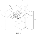
- FIG. 1 is a schematic structural diagram of a carrying robot in an initial state according to an embodiment of this application.
- the carrying robot includes a robot body 100 and a handling device 200.
- the robot body 100 includes a movable chassis 110, a shelving unit 120, and a lifting assembly (not shown in the figure).
- the shelving unit 120 is mounted to the movable chassis 110, and the shelving unit 120 includes more than two shelf board assemblies distributed at different height.
- Each shelf board assembly includes a shelf board 121 for placing goods.
- the lifting assembly is configured to drive the handling device 200 to rise or fall relative to the shelving unit 120, so that the handling device 200 is at the same height as the shelf board 121 or a stationary rack 400.
- FIG. 1 is a schematic structural diagram of a carrying robot in an initial state according to an embodiment of this application.
- the carrying robot includes a robot body 100 and a handling device 200.
- the robot body 100 includes a movable chassis 110, a shelving unit 120, and a lifting assembly (not shown in the figure).
- the handling device 200 includes a rotary assembly 210, a fork bracket 220, and a fork 300.
- the fork bracket 220 is mounted to the shelving unit 120 and can be lifted or lowered relative to the shelving unit 120 with an action of a lifting assembly.
- the fork 300 and the rotary assembly 210 are both mounted to the fork bracket 220.
- the fork 300 is rotatable relative to the fork bracket 220 in a vertical direction with an action of the rotary assembly 210.
- the fork 300 is used for carrying goods to the shelf board 121 at the same height as the fork 300 or used for moving out the goods from the shelf board 121 at the same height as the fork 300.
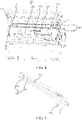
- FIG. 3 is a schematic structural diagram of a movable arm of a handling device in an extended state according to an embodiment of this application.
- the fork 300 is provided with a symmetry axis S1 and includes a telescopic arm, a temporary storage tray 320, and a sliding assembly 330.
- the telescopic arm includes a fixed arm 311, a movable arm 312, a pusher assembly 340, and a driving assembly.
- the fixed arm 311 includes an underframe 317 and two side walls 318 that are fixedly connected to the underframe 317.
- the underframe 317 is mounted to the rotary assembly 210.
- the movable arm 312 is connected to the side wall 318 of the fixed arm 311, and an other end thereof is connected to the pusher assembly 340.
- the movable arm 312 is telescopically movable relative to the fixed arm 311 along the symmetry axis S1 with an action of the driving assembly.
- the pusher assembly 340 is configured to pull in or push out goods during the telescopic movement of the movable arm 312, and the temporary storage tray 320 is mounted to the underframe 317 of the fixed arm 311 and is used for temporarily storing the goods pulled by the pusher assembly 340.
- the sliding assembly 330 is mounted between the underframe 317 of the fixed arm 311 and the temporary storage tray 320, and is capable of pushing the temporary storage tray 320 to make the temporary storage tray 320 extend relative to the fixed arm 311 along the symmetry axis S1.
- An extending direction of the temporary storage tray 320 is consistent with an extending direction of the movable arm 312.
- quantities of the side walls 318 of the fixed arm 311 and the movable arms 312 are both two.
- the two side walls 318 and the two movable arms 312 are symmetrically disposed on two opposite sides of the symmetry axis S1.
- Each movable arm 312 includes a first arm section 313 and a second arm section 315.
- the first arm section 313 is mounted to the fixed arm 311, and the second arm section 315 is mounted to the first arm section 313.
- FIG. 5 is a schematic structural diagram of a first arm section according to an embodiment of this application
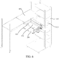
- FIG. 6 is a schematic structural diagram of a handling device when facing to a stationary rack according to an embodiment of this application. As shown in FIG.
- the driving assembly includes a first driving assembly 350 and a second driving assembly 360.
- the first arm section 313 is telescopically movable relative to the fixed arm 311 with an action of the first driving assembly 350
- the second arm section 315 is telescopically movable relative to the first arm section 313 with an action of the second driving assembly 360.
- the fixed arm 311 is an outer arm
- the first arm section 313 is a middle arm
- the second arm section 315 is an inner arm.
- the middle arm is mounted to an inner side of a side wall of the outer arm
- the inner arm is mounted to an inner side of the middle arm.
- the middle arm is telescopically movable relative to the outer arm with the action of the first driving assembly 350, and the inner arm is telescopically movable relative to the middle arm with the action of the second driving assembly 360.
- the fixed arm 311 may further be an inner arm
- the first arm section 313 is a middle arm
- the second arm section 315 is an outer arm.
- the middle arm is mounted to an outer side of a side wall of the inner arm
- the outer arm is mounted to an outer side of the middle arm.
- the number of movable arms 312 is not limited to two, and in other embodiments, the number of movable arms 312 may be one.
- the movable arm 312 may include only the inner arm, but not the middle arm.
- the inner arm is mounted to the inner side of the side wall of the outer arm, and the inner arm is telescopically movable relative to the outer arm along the symmetry axis S1 with the action of the driving assembly.
- the movable arm 312 may include an inner arm and more than two middle arms. The movable arm 312 is telescopically movable relative to the outer arm along the symmetry axis S1 with the action of the driving assembly.
- the sliding assembly 330 includes a spring 331.
- One end of the spring 331 is connected to the underframe 317 of the fixed arm 311, and an other end thereof is connected to the temporary storage tray 320.
- the temporary storage tray 320 extends out relative to the fixed arm 311 with the push of an elastic force of the spring 331.
- FIG. 7 is a schematic structural diagram of a handling device when pulling goods according to an embodiment of this application. As shown in FIG. 7 , when the temporary storage tray 320 extends relative to the fixed arm 311, a free end 321 of the temporary storage tray 320 may protrude from the fixed arm 311.
- FIG. 7 is a schematic structural diagram of a handling device when pulling goods according to an embodiment of this application. As shown in FIG. 7 , when the temporary storage tray 320 extends relative to the fixed arm 311, a free end 321 of the temporary storage tray 320 may protrude from the fixed arm 311.
- the sliding assembly 330 includes a spring 331, a guide rod 332, and a sliding block 333.
- the guide rod 332 is fixed to the fixed arm 311, and the spring 331 and the sliding block 333 are both sleeved on the guide rod 332.
- the temporary storage tray 320 is connected to the sliding block 333, and the temporary storage tray 320 and the sliding block 333 are slidable along the guide rod 332 with the elastic action of the spring 331.
- a stopper 334 is disposed on the guide rod 332 to prevent the temporary storage tray 320 and the sliding block 333 from slipping off the guide rod 332.
- this application does not limit the number of guide rods 332, sliding blocks 333, and springs 331 in the sliding assembly 330.
- two guide rods 332 are disposed, four sliding blocks 333 are disposed, and two springs 331 are disposed. It may be understood that, in other embodiments, one guide rod or other number of guide rods 332 may be disposed, one sliding block or other number of sliding blocks 333 may be disposed, and one spring or other number of springs 331 may be disposed.
- the pusher assembly 340 is mounted to the second arm section 315.
- the pusher assembly 340 includes a fixed pusher 342, a movable pusher 341, and a pusher driving member 343.
- the movable pusher 341 is mounted to a top end 316 of the second arm section 315. It may be understood that the top end 316 mentioned herein refers to an end farthest from the fixed arm 311 when the movable arm 312 extends relative to the fixed arm 311 along the symmetry axis S1.
- the fixed pusher 342 is mounted to an end of the second arm section 315 facing away from the movable pusher 341, and the pusher driving member 343 is connected to the movable pusher 341 for driving the movable pusher 341 to be folded or unfolded relative to the second arm section 315.
- the movable pusher 341 When the movable pusher 341 is unfolded relative to the second arm section 315, the movable pusher 341 protrudes from the second arm section 315 in a direction close to the symmetry axis S1, as shown in FIG. 2 .
- the movable pusher 341 and the second arm section 315 substantially overlap, as shown in FIG. 3 .
- the pusher driving member 343 is a pusher motor.
- the movable pusher 341 is directly driven by the pusher motor.
- the pusher motor is configured to drive the movable pusher 341 to rotate relative to the second arm section 315, so that the movable pusher 341 is unfolded or folded relative to the second arm section 315.
- the movement manner of the movable pusher 341 is not limited to rotation.
- the movable pusher 341 may extend out of the second arm section 315 or retract into the second arm section 315.
- the first driving assembly 350 is disposed on the fixed arm 311 and includes a chain wheel mechanism 351 and a driving member 352. An output end of the driving member 352 is connected to a driving chain wheel of the chain wheel mechanism 351.
- a connecting plate 314 is disposed on the first arm section 313, and the connecting plate 314 is fixedly connected to a link chain of the chain wheel mechanism 351.
- the first driving assembly 350 is configured to drive the driving chain wheel to rotate. Since the first arm section 313 is fixedly connected to the link chain of the chain wheel mechanism 351 by using the connecting plate 314, the chain wheel mechanism 351 can drive, by using the connecting plate 314, the first arm section 313 to move relative to the fixed arm 311 along the symmetry axis S1.
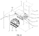
- FIG. 8 is a schematic structural diagram of a movable arm when retracting after a handling device pulls goods according to an embodiment of this application.
- the connecting plate 314 abuts against the rib 322. Therefore, the temporary storage tray 320 can be pushed to retract relative to the fixed arm 311, and the temporary storage tray 320 is pushed back to the original position.
- the temporary storage tray 320 is pushed back to the original position, as shown in FIG.
- the spring 331 is in a compressed state, and the temporary storage tray 320 is blocked by the connecting plate 314 and is located on the underframe 317 of the fixed arm 311.
- the connecting plate 314 extends relative to the fixed arm 311 along with the first arm section 313 with the action of the first driving assembly 350, as shown in FIG. 7 , the temporary storage tray 320 loses obstruction and is pushed out with an elastic restoring force of the spring 331, so that the free end 321 of the temporary storage tray 320 protrudes from the fixed arm 311.
- a direction in which the temporary storage tray 320 is pushed out by the spring 331 is consistent with a direction in which the movable arm 312 extends relative to the fixed arm 311. It may be understood that, according to the actual condition, the chain wheel mechanism 351 of the first driving assembly 350 may be replaced with a pulley mechanism or the like.
- the spring 331 is a compression spring. It may be understood that in other embodiments, the spring 331 may be a tension spring.
- the connecting plate 314 blocks the temporary storage tray 320, and the temporary storage tray 320 is located on the underframe 317 of the fixed arm 311. Once the connecting plate 314 extends relative to the fixed arm 311 along with the first arm section 313 with the action of the first driving assembly 350, the temporary storage tray 320 loses obstruction and is pulled out with the elastic restoring force of the spring 331.
- the second driving assembly 360 includes a movable pulley 361 and a strop 362.
- the movable pulley 361 is mounted to the first arm section 313, and a middle part of the strop 362 is bent, so that two ends of the strop 362 are disposed opposite to each other.
- the middle part of the strop 362 is sleeved on the movable pulley 361, one end of the strop 362 is fixedly connected to the fixed arm 311, and an other end thereof is fixedly connected to the second arm section 315.
- the movable pulley 361 and the strop 362 form a movable pulley structure.
- the second arm section 315 moves at a second speed relative to the fixed arm 311.
- the second speed is twice the first speed.
- the movable pulley 361 is a flat pulley
- the strop 362 is an open-loop flat belt. It may be understood that, in other embodiments, the movable pulley 361 may be a chain wheel, and the strop 362 may be a link chain.
- Step 1 The handling device 200 is raised or lowered relative to the shelving unit 120 with an action of the lifting assembly, so that the symmetry axis S1 of the fork 300 is at a same height as the container on the stationary rack 400.
- Step 2 As shown in FIG.
- Step 3 As shown in FIG. 7 , the movable arm 312 extends relative to the fixed arm 311 along the symmetry axis S1 with the action of the driving assembly.
- the temporary storage tray 320 loses the blocking of the connecting plate 314 and is then pushed out with the action of the elastic restoring force of the spring 331, so that the free end 321 of the temporary storage tray 320 protrudes from the fixed arm 311, and the free end 321 of the temporary storage tray 320 is closer to the stationary rack 400.
- the movable pusher 341 mounted to the top end 316 of the second arm section 315 is folded relative to the second arm section 315, and the top end 316 of the second arm section 315 moves from a side of the container towards the temporary storage tray 320 to a side of the container away from the temporary storage tray 320.
- Step 4 The movable pusher 341 is unfolded relative to the second arm section 315 with an action of the pusher driving member 343, and then the movable arm 312 retracts relative to the fixed arm 311 along the symmetry axis S1 with the action of the driving assembly, so that the movable pusher 341 can pull the container onto the temporary storage tray 320. As shown in FIG.
- FIG. 9 is a schematic structural diagram of a handling device when orienting towards a shelving unit according to an embodiment of this application.
- the fork 300 rotates with an action of the rotary assembly 210, so that the free end 321 of the temporary storage tray 320 orients towards the shelf board 121 on the shelving unit 120.
- the handling device 200 is lifted or lowered relative to the shelving unit 120 with the action of the lifting assembly, so that the symmetry axis S1 of the fork 300 is at the same height as one empty shelf board 121 on the shelving unit 120.
- FIG. 10 is a schematic structural diagram of a handling device when pushing goods on a temporary storage tray to a shelving unit according to an embodiment of this application. As shown in FIG.
- the movable arm 312 extends relative to the fixed arm 311 along the symmetry axis S1 with an action of the driving assembly.
- the temporary storage tray 320 loses the blocking of the first arm section 313 and is then pushed out by the elastic restoring force of the spring 331, so that the free end 321 of the temporary storage tray 320 protrudes from the fixed arm 311, and the temporary storage tray 320 is closer to the shelf board 121 on the shelving unit 120.
- the container is pushed onto the empty shelf board 121 of the shelving unit 120 by the fixed pusher 342.
- the movable pusher 341 mounted to the top end 316 of the second arm section 315 may be folded relative to the second arm section 315 or may be unfolded relative to the second arm section 315.
- the movable pusher 341 is unfolded relative to the second arm section 315, and the unfolded movable pusher 341 can prevent the container from falling from an other end of the shelf board 121.
- Step 8 The movable pusher 341 is folded relative to the second arm section 315 with the action of the pusher driving member 343 (in another embodiment, this step may also be performed in step 5, step 6, or step 7.
- step 8 If the movable pusher 341 has been folded relative to the second arm section 315 in step 7, then this step can be omitted in step 8).
- the movable arm 312 retracts relative to the fixed arm 311 along the symmetry axis S1 with the action of the driving assembly.
- the connecting plate 314 on the first arm section 313 abuts against the rib 322 on the temporary storage tray 320.
- the movable arm 312 continues to retract relative to the fixed arm 311 along the symmetry axis S1 with the action of the driving assembly, and pushes the temporary storage tray 320 to make the temporary storage tray retract relative to the fixed arm 311 along the symmetry axis S1, thereby pushing the temporary storage tray 320 back to the original position.
- the carrying robot of this application may further carry the container on the shelf board 121 of the shelving unit 120 to the stationary rack 400. This process is contrary to the above process, and the details will not be described herein again.
- the sliding assembly is disposed between the fixed arm of the handling device and the temporary storage tray.
- the sliding assembly is capable of pushing the temporary storage tray to make the temporary storage tray extend relative to the fixed arm, and the extending direction of the temporary storage tray is consistent with the extending direction of the movable arm. Therefore, when the fork of this application pulls in or pushes out the goods, the container can be stably transferred between the stationary rack and the temporary storage tray and will not fall off during the transfer.
Landscapes
- Engineering & Computer Science (AREA)
- Transportation (AREA)
- Structural Engineering (AREA)
- Mechanical Engineering (AREA)
- Civil Engineering (AREA)
- Life Sciences & Earth Sciences (AREA)
- Geology (AREA)
- Warehouses Or Storage Devices (AREA)
- Load-Engaging Elements For Cranes (AREA)
Applications Claiming Priority (2)
| Application Number | Priority Date | Filing Date | Title |
|---|---|---|---|
| CN201921546485.9U CN211056639U (zh) | 2019-09-17 | 2019-09-17 | 货叉及搬运机器人 |
| PCT/CN2020/115764 WO2021052393A1 (fr) | 2019-09-17 | 2020-09-17 | Fourche de palette et robot de transport |
Publications (4)
| Publication Number | Publication Date |
|---|---|
| EP4032848A1 true EP4032848A1 (fr) | 2022-07-27 |
| EP4032848A4 EP4032848A4 (fr) | 2022-11-30 |
| EP4032848C0 EP4032848C0 (fr) | 2025-07-16 |
| EP4032848B1 EP4032848B1 (fr) | 2025-07-16 |
Family
ID=71594335
Family Applications (1)
| Application Number | Title | Priority Date | Filing Date |
|---|---|---|---|
| EP20866644.6A Active EP4032848B1 (fr) | 2019-09-17 | 2020-09-17 | Fourche de palette et robot de transport |
Country Status (10)
| Country | Link |
|---|---|
| US (1) | US11548770B2 (fr) |
| EP (1) | EP4032848B1 (fr) |
| JP (2) | JP7360543B2 (fr) |
| KR (2) | KR102729700B1 (fr) |
| CN (2) | CN211056639U (fr) |
| AU (2) | AU2020350944B2 (fr) |
| CA (1) | CA3149595C (fr) |
| DE (2) | DE212020000724U1 (fr) |
| ES (1) | ES3036820T3 (fr) |
| WO (1) | WO2021052393A1 (fr) |
Families Citing this family (24)
| Publication number | Priority date | Publication date | Assignee | Title |
|---|---|---|---|---|
| US11807451B2 (en) | 2019-09-17 | 2023-11-07 | Hai Robotics Co., Ltd. | Fork and carrying robot |
| CN211056639U (zh) * | 2019-09-17 | 2020-07-21 | 深圳市海柔创新科技有限公司 | 货叉及搬运机器人 |
| EP4049961A4 (fr) * | 2019-10-23 | 2023-11-29 | Shanghai Quicktron Intelligent Technology Co., Ltd | Dispositif télescopique et robot de transport |
| CN211197466U (zh) * | 2019-11-19 | 2020-08-07 | 深圳市海柔创新科技有限公司 | 一种搬运装置及具有此搬运装置的搬运机器人 |
| CN114684516B (zh) * | 2020-12-31 | 2023-05-02 | 深圳市海柔创新科技有限公司 | 货叉组件的控制方法、货叉组件及机器人 |
| CN112758588B (zh) * | 2021-01-28 | 2026-07-10 | 北京极智嘉科技股份有限公司 | 一种货箱搬运系统、机器人和货箱搬运方法 |
| JP7533268B2 (ja) | 2021-02-16 | 2024-08-14 | トヨタ自動車株式会社 | 搬送システム及び搬送方法 |
| JP7407755B2 (ja) * | 2021-03-11 | 2024-01-04 | 日本金銭機械株式会社 | 物品搬送ロボットシステムおよび物品載置棚 |
| CN115557130A (zh) * | 2021-07-01 | 2023-01-03 | 深圳市海柔创新科技有限公司 | 货叉组件、搬运机器人及仓储系统 |
| CN113479822B (zh) * | 2021-08-04 | 2023-02-10 | 杭州海康机器人股份有限公司 | 搬运装置 |
| CN113788259B (zh) * | 2021-09-18 | 2023-07-18 | 深圳市海柔创新科技有限公司 | 搬运机器人 |
| CN115893271B (zh) * | 2021-09-24 | 2025-11-28 | 深圳市海柔创新科技有限公司 | 货叉机构及搬运机器人 |
| CN113895970B (zh) * | 2021-11-19 | 2024-07-19 | 成都海科机械设备制造有限公司 | 一种卸垛码垛装置及其使用方法 |
| CN114772129A (zh) * | 2022-05-17 | 2022-07-22 | 无锡奥特维旭睿科技有限公司 | 一种电池包分档机 |
| CN114955423A (zh) * | 2022-05-31 | 2022-08-30 | 菲尼克斯(南京)智能制造技术工程有限公司 | 集成于agv小车的箱体搬运系统及箱体搬运方法 |
| US12552602B1 (en) * | 2022-06-14 | 2026-02-17 | Amazon Technologies, Inc. | Inventory system with item retrieval |
| CN217626404U (zh) * | 2022-06-30 | 2022-10-21 | 深圳市海柔创新科技有限公司 | 货叉机构及码垛机器人 |
| CN115180556A (zh) * | 2022-07-21 | 2022-10-14 | 真金火炼(上海)智能科技有限公司 | 一种重载货箱双向同步下架机器人及其操作方法 |
| CN115384992B (zh) * | 2022-08-22 | 2025-08-29 | 安徽宝杰生物科技有限公司 | 一种发酵饲料立体储存系统 |
| CN117657645A (zh) * | 2022-08-26 | 2024-03-08 | 深圳市海柔创新科技有限公司 | 搬运装置、搬运机器人、仓储系统及取放货物的方法 |
| CN116534571B (zh) * | 2023-03-21 | 2025-08-05 | 臻越自动化技术(上海)有限公司 | 一种喷胶用自动转移装置及转移方法 |
| CN116788744B (zh) * | 2023-07-11 | 2024-09-24 | 广州力生机器人技术有限公司 | 一种立体仓库的物流拣货装置 |
| CN117263082B (zh) * | 2023-08-07 | 2026-06-19 | 中国铁道科学研究院集团有限公司铁道建筑研究所 | 一种应用在隧道结构下沉中的plc伺服抬升系统 |
| CN121158692A (zh) * | 2024-06-18 | 2025-12-19 | 深圳市米塔机器人有限公司 | 一种伸缩臂机构、货叉组件及搬运机器人 |
Family Cites Families (31)
| Publication number | Priority date | Publication date | Assignee | Title |
|---|---|---|---|---|
| DE3020791C2 (de) * | 1980-05-31 | 1982-11-25 | psb GmbH Förderanlagen und Lagertechnik, 6780 Pirmasens | Regalbediengerät für Hochregallager |
| JPH08268552A (ja) * | 1995-03-31 | 1996-10-15 | Nkk Corp | 層別ピッキング装置の制御方法 |
| US6619902B1 (en) * | 1997-02-11 | 2003-09-16 | Stein & Associates, P.C. | Automated storage and retrieval system and indexing/insertion extraction mechanism therefor |
| JP3887904B2 (ja) * | 1997-09-10 | 2007-02-28 | 株式会社豊田自動織機 | スタッカクレーン用移載装置の制御装置 |
| DE10140643B4 (de) * | 2001-04-27 | 2007-04-05 | Kht Kommissionier- Und Handhabungstechnik Gmbh | Regallagersystem |
| AT500228B1 (de) * | 2003-05-20 | 2007-07-15 | Tgw Transportgeraete Gmbh | Teleskopschubarm, insbesondere für eine lastaufnahmevorrichtung |
| JP4793654B2 (ja) * | 2006-06-13 | 2011-10-12 | 株式会社ダイフク | スライド式のフォーク装置 |
| CN100560470C (zh) * | 2006-06-13 | 2009-11-18 | 大福株式会社 | 滑动式叉装置 |
| JP2008100774A (ja) | 2006-10-17 | 2008-05-01 | Asyst Technologies Japan Inc | 搬送台車及び搬送台車による被搬送物移送方法 |
| JP5432917B2 (ja) * | 2008-10-27 | 2014-03-05 | デマティック アカウンティング サービシーズ ゲーエムベーハー | 立体自動倉庫用の移載シャトル |
| US8465243B2 (en) * | 2009-07-16 | 2013-06-18 | Wes van Ooyen | Method and apparatus for picking a package from a dispensing system |
| JP5581715B2 (ja) * | 2010-02-04 | 2014-09-03 | 株式会社Ihi | フォーク装置 |
| JP5598543B2 (ja) * | 2010-06-17 | 2014-10-01 | 村田機械株式会社 | 移載装置および移載方法 |
| KR102314503B1 (ko) * | 2013-09-13 | 2021-10-19 | 심보틱 엘엘씨 | 자율 저장 및 인출 시스템 |
| JP6350166B2 (ja) * | 2014-09-19 | 2018-07-04 | 株式会社ダイフク | 物品搬送台車 |
| JP6260584B2 (ja) | 2015-06-19 | 2018-01-17 | 村田機械株式会社 | 移載装置 |
| EP3712815B1 (fr) * | 2017-11-14 | 2024-01-10 | Hai Robotics Co., Ltd. | Robot de transport et procédé de ramassage basé sur un robot de transport |
| CN108069180A (zh) * | 2017-11-14 | 2018-05-25 | 深圳市海柔创新科技有限公司 | 机器人 |
| CN208022646U (zh) | 2018-01-16 | 2018-10-30 | 浙江国自机器人技术有限公司 | 一种货箱搬运机器人伸缩叉齿双向调平机构 |
| CN207748386U (zh) * | 2018-01-22 | 2018-08-21 | 合肥工业大学 | 一种双倍行程穿梭车伸叉机构 |
| CN208217598U (zh) * | 2018-02-02 | 2018-12-11 | 尊道(上海)自动化设备有限公司 | 四向行走提升物流搬运仓储车的抱夹货叉机构 |
| CN208499400U (zh) * | 2018-05-29 | 2019-02-15 | 北京起重运输机械设计研究院有限公司 | 一种货叉机构 |
| CN208666177U (zh) | 2018-07-26 | 2019-03-29 | 浙江迈睿机器人有限公司 | 一种用于货箱拣选仓储机器人的叉取装置 |
| CN209160601U (zh) * | 2018-09-07 | 2019-07-26 | 深圳市海柔创新科技有限公司 | 一种搬运机器人 |
| CN209023571U (zh) * | 2018-09-07 | 2019-06-25 | 深圳市海柔创新科技有限公司 | 一种搬运机器人 |
| CN209210300U (zh) | 2018-10-16 | 2019-08-06 | 无锡弘宜智能科技有限公司 | 前叉后货架式搬运机器人 |
| CN110271805B (zh) | 2018-12-29 | 2020-09-22 | 杭州慧盈智能科技有限公司 | 一种用于仓储的机器人及其工作方法 |
| CN109748027A (zh) * | 2019-03-11 | 2019-05-14 | 杭州蓝芯科技有限公司 | 一种物料箱自动拣选机器人及其控制方法 |
| JP7081553B2 (ja) * | 2019-03-29 | 2022-06-07 | 株式会社ダイフク | 移載装置 |
| CN109941653B (zh) | 2019-04-19 | 2024-11-15 | 北京极智嘉科技股份有限公司 | 一种搬运机器人 |
| CN211056639U (zh) * | 2019-09-17 | 2020-07-21 | 深圳市海柔创新科技有限公司 | 货叉及搬运机器人 |
-
2019
- 2019-09-17 CN CN201921546485.9U patent/CN211056639U/zh active Active
-
2020
- 2020-09-17 AU AU2020350944A patent/AU2020350944B2/en active Active
- 2020-09-17 KR KR1020227009274A patent/KR102729700B1/ko active Active
- 2020-09-17 CA CA3149595A patent/CA3149595C/fr active Active
- 2020-09-17 CN CN202080064791.8A patent/CN114514189B/zh active Active
- 2020-09-17 EP EP20866644.6A patent/EP4032848B1/fr active Active
- 2020-09-17 DE DE212020000724.1U patent/DE212020000724U1/de active Active
- 2020-09-17 KR KR1020247037082A patent/KR102840884B1/ko active Active
- 2020-09-17 ES ES20866644T patent/ES3036820T3/es active Active
- 2020-09-17 JP JP2022512817A patent/JP7360543B2/ja active Active
- 2020-09-17 DE DE202020005899.8U patent/DE202020005899U1/de active Active
- 2020-09-17 WO PCT/CN2020/115764 patent/WO2021052393A1/fr not_active Ceased
-
2022
- 2022-03-17 US US17/697,527 patent/US11548770B2/en active Active
-
2023
- 2023-09-25 JP JP2023161544A patent/JP7561940B2/ja active Active
-
2024
- 2024-01-08 AU AU2024200110A patent/AU2024200110B2/en active Active
Also Published As
| Publication number | Publication date |
|---|---|
| AU2024200110B2 (en) | 2025-07-10 |
| AU2024200110A1 (en) | 2024-01-25 |
| CN114514189A (zh) | 2022-05-17 |
| CN114514189B (zh) | 2023-06-06 |
| US11548770B2 (en) | 2023-01-10 |
| ES3036820T3 (en) | 2025-09-24 |
| WO2021052393A1 (fr) | 2021-03-25 |
| CA3149595C (fr) | 2024-05-28 |
| JP7360543B2 (ja) | 2023-10-12 |
| AU2020350944A1 (en) | 2022-03-24 |
| AU2020350944B2 (en) | 2023-11-02 |
| KR102729700B1 (ko) | 2024-11-14 |
| JP2022545523A (ja) | 2022-10-27 |
| KR102840884B1 (ko) | 2025-08-01 |
| EP4032848C0 (fr) | 2025-07-16 |
| KR20240162601A (ko) | 2024-11-15 |
| EP4032848B1 (fr) | 2025-07-16 |
| CN211056639U (zh) | 2020-07-21 |
| DE202020005899U1 (de) | 2023-02-06 |
| KR20220061141A (ko) | 2022-05-12 |
| EP4032848A4 (fr) | 2022-11-30 |
| JP2023164756A (ja) | 2023-11-10 |
| JP7561940B2 (ja) | 2024-10-04 |
| DE212020000724U1 (de) | 2022-06-29 |
| CA3149595A1 (fr) | 2021-03-25 |
| US20220204329A1 (en) | 2022-06-30 |
Similar Documents
| Publication | Publication Date | Title |
|---|---|---|
| US11548770B2 (en) | Fork and carrying robot | |
| US12509296B2 (en) | Fork and carrying robot | |
| CN209758195U (zh) | 一种搬运机器人 | |
| CN215158010U (zh) | 货叉组件、搬运机器人及仓储系统 | |
| CN211813282U (zh) | 一种立式支架 | |
| HK40069547A (en) | Pallet fork and carrying robot | |
| HK40069547B (en) | Pallet fork and carrying robot | |
| CN213263335U (zh) | 一种新型物流托盘 | |
| CN215796168U (zh) | 一种智能存储仓库防倾倒小车 | |
| CN216637684U (zh) | 货叉组件及仓储机器人 | |
| TWM631165U (zh) | 貨叉裝置及搬運機器人 | |
| CN216547922U (zh) | 储物托盘、仓储机器人、仓储货架及仓储系统 | |
| CN223356509U (zh) | 一种机器人、机器人的执行机构和仓储系统 | |
| CN220265140U (zh) | 一种具有货物暂存结构的堆垛机 | |
| CN223267547U (zh) | 一种堆栈缓存设备的稳固支撑框架 | |
| CN119037976B (zh) | 一种用于吨袋垛存取的间隔式堆垛机载物台及其方法 | |
| CN220843977U (zh) | 一种仓储下货机构 | |
| CN118125021A (zh) | 一种桁架式物流件转运装置 | |
| CN118419449A (zh) | 搬运设备和仓储系统 | |
| CN120664477A (zh) | 一种具有兼容性的夹抱式伸缩货叉及其使用方法 | |
| JPS61136829A (ja) | 物品パレタイジング用ロボツトシステム |
Legal Events
| Date | Code | Title | Description |
|---|---|---|---|
| STAA | Information on the status of an ep patent application or granted ep patent |
Free format text: STATUS: THE INTERNATIONAL PUBLICATION HAS BEEN MADE |
|
| PUAI | Public reference made under article 153(3) epc to a published international application that has entered the european phase |
Free format text: ORIGINAL CODE: 0009012 |
|
| STAA | Information on the status of an ep patent application or granted ep patent |
Free format text: STATUS: REQUEST FOR EXAMINATION WAS MADE |
|
| 17P | Request for examination filed |
Effective date: 20220412 |
|
| AK | Designated contracting states |
Kind code of ref document: A1 Designated state(s): AL AT BE BG CH CY CZ DE DK EE ES FI FR GB GR HR HU IE IS IT LI LT LU LV MC MK MT NL NO PL PT RO RS SE SI SK SM TR |
|
| REG | Reference to a national code |
Ref country code: HK Ref legal event code: DE Ref document number: 40069547 Country of ref document: HK |
|
| A4 | Supplementary search report drawn up and despatched |
Effective date: 20221028 |
|
| RIC1 | Information provided on ipc code assigned before grant |
Ipc: B66F 9/19 20060101ALI20221024BHEP Ipc: B66F 9/075 20060101ALI20221024BHEP Ipc: B66F 9/06 20060101ALI20221024BHEP Ipc: B66F 9/12 20060101AFI20221024BHEP |
|
| DAV | Request for validation of the european patent (deleted) | ||
| DAX | Request for extension of the european patent (deleted) | ||
| RIC1 | Information provided on ipc code assigned before grant |
Ipc: B66F 9/19 20060101ALI20230320BHEP Ipc: B66F 9/075 20060101ALI20230320BHEP Ipc: B66F 9/06 20060101ALI20230320BHEP Ipc: B66F 9/12 20060101AFI20230320BHEP |
|
| STAA | Information on the status of an ep patent application or granted ep patent |
Free format text: STATUS: EXAMINATION IS IN PROGRESS |
|
| 17Q | First examination report despatched |
Effective date: 20240514 |
|
| GRAP | Despatch of communication of intention to grant a patent |
Free format text: ORIGINAL CODE: EPIDOSNIGR1 |
|
| STAA | Information on the status of an ep patent application or granted ep patent |
Free format text: STATUS: GRANT OF PATENT IS INTENDED |
|
| INTG | Intention to grant announced |
Effective date: 20250226 |
|
| GRAS | Grant fee paid |
Free format text: ORIGINAL CODE: EPIDOSNIGR3 |
|
| GRAA | (expected) grant |
Free format text: ORIGINAL CODE: 0009210 |
|
| STAA | Information on the status of an ep patent application or granted ep patent |
Free format text: STATUS: THE PATENT HAS BEEN GRANTED |
|
| AK | Designated contracting states |
Kind code of ref document: B1 Designated state(s): AL AT BE BG CH CY CZ DE DK EE ES FI FR GB GR HR HU IE IS IT LI LT LU LV MC MK MT NL NO PL PT RO RS SE SI SK SM TR |
|
| REG | Reference to a national code |
Ref country code: GB Ref legal event code: FG4D |
|
| REG | Reference to a national code |
Ref country code: CH Ref legal event code: EP |
|
| REG | Reference to a national code |
Ref country code: DE Ref legal event code: R096 Ref document number: 602020054766 Country of ref document: DE |
|
| REG | Reference to a national code |
Ref country code: IE Ref legal event code: FG4D |
|
| U01 | Request for unitary effect filed |
Effective date: 20250729 |
|
| U07 | Unitary effect registered |
Designated state(s): AT BE BG DE DK EE FI FR IT LT LU LV MT NL PT RO SE SI Effective date: 20250805 |
|
| REG | Reference to a national code |
Ref country code: ES Ref legal event code: FG2A Ref document number: 3036820 Country of ref document: ES Kind code of ref document: T3 Effective date: 20250924 |
|
| PGFP | Annual fee paid to national office [announced via postgrant information from national office to epo] |
Ref country code: GB Payment date: 20250923 Year of fee payment: 6 |
|
| U20 | Renewal fee for the european patent with unitary effect paid |
Year of fee payment: 6 Effective date: 20250922 |
|
| PG25 | Lapsed in a contracting state [announced via postgrant information from national office to epo] |
Ref country code: IS Free format text: LAPSE BECAUSE OF FAILURE TO SUBMIT A TRANSLATION OF THE DESCRIPTION OR TO PAY THE FEE WITHIN THE PRESCRIBED TIME-LIMIT Effective date: 20251116 |
|
| PG25 | Lapsed in a contracting state [announced via postgrant information from national office to epo] |
Ref country code: NO Free format text: LAPSE BECAUSE OF FAILURE TO SUBMIT A TRANSLATION OF THE DESCRIPTION OR TO PAY THE FEE WITHIN THE PRESCRIBED TIME-LIMIT Effective date: 20251016 |
|
| PG25 | Lapsed in a contracting state [announced via postgrant information from national office to epo] |
Ref country code: HR Free format text: LAPSE BECAUSE OF FAILURE TO SUBMIT A TRANSLATION OF THE DESCRIPTION OR TO PAY THE FEE WITHIN THE PRESCRIBED TIME-LIMIT Effective date: 20250716 |
|
| PG25 | Lapsed in a contracting state [announced via postgrant information from national office to epo] |
Ref country code: GR Free format text: LAPSE BECAUSE OF FAILURE TO SUBMIT A TRANSLATION OF THE DESCRIPTION OR TO PAY THE FEE WITHIN THE PRESCRIBED TIME-LIMIT Effective date: 20251017 |
|
| PG25 | Lapsed in a contracting state [announced via postgrant information from national office to epo] |
Ref country code: PL Free format text: LAPSE BECAUSE OF FAILURE TO SUBMIT A TRANSLATION OF THE DESCRIPTION OR TO PAY THE FEE WITHIN THE PRESCRIBED TIME-LIMIT Effective date: 20250716 |
|
| PG25 | Lapsed in a contracting state [announced via postgrant information from national office to epo] |
Ref country code: RS Free format text: LAPSE BECAUSE OF FAILURE TO SUBMIT A TRANSLATION OF THE DESCRIPTION OR TO PAY THE FEE WITHIN THE PRESCRIBED TIME-LIMIT Effective date: 20251016 |
|
| PGFP | Annual fee paid to national office [announced via postgrant information from national office to epo] |
Ref country code: ES Payment date: 20251020 Year of fee payment: 6 |
|
| PG25 | Lapsed in a contracting state [announced via postgrant information from national office to epo] |
Ref country code: SM Free format text: LAPSE BECAUSE OF FAILURE TO SUBMIT A TRANSLATION OF THE DESCRIPTION OR TO PAY THE FEE WITHIN THE PRESCRIBED TIME-LIMIT Effective date: 20250716 |
|
| PG25 | Lapsed in a contracting state [announced via postgrant information from national office to epo] |
Ref country code: CZ Free format text: LAPSE BECAUSE OF FAILURE TO SUBMIT A TRANSLATION OF THE DESCRIPTION OR TO PAY THE FEE WITHIN THE PRESCRIBED TIME-LIMIT Effective date: 20250716 |
|
| PG25 | Lapsed in a contracting state [announced via postgrant information from national office to epo] |
Ref country code: SK Free format text: LAPSE BECAUSE OF FAILURE TO SUBMIT A TRANSLATION OF THE DESCRIPTION OR TO PAY THE FEE WITHIN THE PRESCRIBED TIME-LIMIT Effective date: 20250716 |
|
| REG | Reference to a national code |
Ref country code: CH Ref legal event code: H13 Free format text: ST27 STATUS EVENT CODE: U-0-0-H10-H13 (AS PROVIDED BY THE NATIONAL OFFICE) Effective date: 20260504 |
|
| PLBE | No opposition filed within time limit |
Free format text: ORIGINAL CODE: 0009261 |
|
| STAA | Information on the status of an ep patent application or granted ep patent |
Free format text: STATUS: NO OPPOSITION FILED WITHIN TIME LIMIT |
|
| REG | Reference to a national code |
Ref country code: CH Ref legal event code: L10 Free format text: ST27 STATUS EVENT CODE: U-0-0-L10-L00 (AS PROVIDED BY THE NATIONAL OFFICE) Effective date: 20260528 |
|
| 26N | No opposition filed |
Effective date: 20260417 |
|
| PG25 | Lapsed in a contracting state [announced via postgrant information from national office to epo] |
Ref country code: MC Free format text: LAPSE BECAUSE OF FAILURE TO SUBMIT A TRANSLATION OF THE DESCRIPTION OR TO PAY THE FEE WITHIN THE PRESCRIBED TIME-LIMIT Effective date: 20250716 |
|
| PG25 | Lapsed in a contracting state [announced via postgrant information from national office to epo] |
Ref country code: CH Free format text: LAPSE BECAUSE OF NON-PAYMENT OF DUE FEES Effective date: 20250930 Ref country code: IE Free format text: LAPSE BECAUSE OF NON-PAYMENT OF DUE FEES Effective date: 20250917 |