EP4032849A1 - Flanschschneide-dosenöffner - Google Patents
Flanschschneide-dosenöffner Download PDFInfo
- Publication number
- EP4032849A1 EP4032849A1 EP19954354.7A EP19954354A EP4032849A1 EP 4032849 A1 EP4032849 A1 EP 4032849A1 EP 19954354 A EP19954354 A EP 19954354A EP 4032849 A1 EP4032849 A1 EP 4032849A1
- Authority
- EP
- European Patent Office
- Prior art keywords
- wheel
- disposed
- clamping handle
- cutting
- cutter
- Prior art date
- Legal status (The legal status is an assumption and is not a legal conclusion. Google has not performed a legal analysis and makes no representation as to the accuracy of the status listed.)
- Withdrawn
Links
Images


Classifications
-
- B—PERFORMING OPERATIONS; TRANSPORTING
- B67—OPENING, CLOSING OR CLEANING BOTTLES, JARS OR SIMILAR CONTAINERS; LIQUID HANDLING
- B67B—APPLYING CLOSURE MEMBERS TO BOTTLES JARS, OR SIMILAR CONTAINERS; OPENING CLOSED CONTAINERS
- B67B7/00—Hand- or power-operated devices for opening closed containers
- B67B7/38—Power-operated cutting devices
-
- B—PERFORMING OPERATIONS; TRANSPORTING
- B67—OPENING, CLOSING OR CLEANING BOTTLES, JARS OR SIMILAR CONTAINERS; LIQUID HANDLING
- B67B—APPLYING CLOSURE MEMBERS TO BOTTLES JARS, OR SIMILAR CONTAINERS; OPENING CLOSED CONTAINERS
- B67B7/00—Hand- or power-operated devices for opening closed containers
- B67B7/30—Hand-operated cutting devices
- B67B7/32—Hand-operated cutting devices propelled by rotary gears or wheels around periphery of container
-
- B—PERFORMING OPERATIONS; TRANSPORTING
- B67—OPENING, CLOSING OR CLEANING BOTTLES, JARS OR SIMILAR CONTAINERS; LIQUID HANDLING
- B67B—APPLYING CLOSURE MEMBERS TO BOTTLES JARS, OR SIMILAR CONTAINERS; OPENING CLOSED CONTAINERS
- B67B7/00—Hand- or power-operated devices for opening closed containers
- B67B7/30—Hand-operated cutting devices
- B67B7/34—Hand-operated cutting devices with rotatable cutters
-
- B—PERFORMING OPERATIONS; TRANSPORTING
- B67—OPENING, CLOSING OR CLEANING BOTTLES, JARS OR SIMILAR CONTAINERS; LIQUID HANDLING
- B67B—APPLYING CLOSURE MEMBERS TO BOTTLES JARS, OR SIMILAR CONTAINERS; OPENING CLOSED CONTAINERS
- B67B7/00—Hand- or power-operated devices for opening closed containers
- B67B7/30—Hand-operated cutting devices
- B67B2007/303—Hand-operated cutting devices can openers
Definitions
- the present invention relates to the technical field of can openers, and in particular, to an edge-breaking can opener.
- the edge-breaking can opener is a tool for performing cutting from an edge of a can cover.
- a type of can opener on the market includes a drive wheel and a cutting wheel that occlude each other for cutting.
- the drive wheel uses a combination of a rotating shaft and a gear disk.
- the gear disk includes a tray gear and a spur gear, and the three are riveted.
- the spur gear and the tray gear are disposed in a manner of being perpendicular to each other . Therefore, when a can cover is clamped and occluded, a location at which the drive wheel is located is relatively low. In this way, a location at which the cutting wheel cuts the can cover is correspondingly relatively deep.
- a protrusion portion ( FIG 10 ) is disposed on an existing cutting wheel, and the protrusion portion ( FIG 10 ) of the cutter wheel plays a role of clamping an edge when a can is opened.
- two clamping handles need to be first opened after the can is opened, to increase a gap between the cutting wheel and the drive wheel. Because the cutting location is relatively deep, a part of the can cover and the can body are tightly occluded after cutting, the can cover cannot be taken out by hand, and pliers need to be used to take out the can cover, which is neither hygienic nor safe.
- An objective of the present invention is to provide a type of edge-breaking can opener for which a hand comes into no contact with a can cover, and the can cover can be directly and conveniently removed after the can cover is cut.
- the edge-breaking can opener is safe and hygienic, and can improve cutting quality and adapt to various types of cans.
- the present invention may be implemented by using the following technical solutions:
- An edge-breaking can opener including a first clamping handle and a second clamping handle, the first clamping handle and the second clamping handle being connected through relative rotation by using a rivet, where a cutting wheel and a limiting groove are disposed on the first clamping handle, a drive wheel is disposed on the second clamping handle, the drive wheel and the cutting wheel are capable of occluding each other through the limiting groove, the cutting wheel includes a fixing shaft, a cutter wheel, a support wheel, and a round cover, an end of the fixing shaft is aslant disposed on the first clamping handle, the round cover, the support wheel, and the cutter wheel are separately sleeved on the fixing shaft from up to bottom, an elastic piece is disposed between the round cover and the support wheel, the cutter wheel is provided with a stepped groove, a spring plate is disposed in the stepped groove, the spring plate is sleeved on the fixing shaft, and the spring plate is provided with an opening.
- the drive wheel includes an integrally formed gear disk and a rotating shaft, the gear disk is connected to one end of the rotating shaft, the rotating shaft is further provided with a straight groove, the straight groove is provided with a card, the gear disk includes a tray gear and a helical gear, the tray gear and the helical gear are aslant disposed, and a round angle is provided between the tray gear and the helical gear.
- the cutter wheel includes an integrally formed rotating portion and a cutter portion protruding outwards, the cutter portion is disposed at a lower portion of the cutter wheel, a boss portion protruding outwards is disposed on the support wheel, and the boss portion is disposed at a lower portion of the support wheel.
- the cutting wheel further includes a cutter wheel washer and a gear washer, the cutter wheel washer is sleeved on the fixing shaft, and is disposed between the cutter wheel and the first clamping handle, a spring plate stopper is disposed on a surface, of the cutter wheel washer, adjacent to the cutter wheel, the spring plate stopper cooperates with the opening, a fixing block for fixing is disposed on the other surface of the cutter wheel washer, and the gear washer is sleeved on the fixing shaft, and is disposed above the cutter wheel and inside the support wheel.
- a fixing sleeve is further disposed on the second clamping handle, a step protruding outwards and an oblique groove are separately disposed on the fixing sleeve, a rivet sleeve is disposed in the oblique groove, the fixing sleeve is disposed on the second clamping handle by passing through the step and the rivet sleeve, the rotating shaft passes through the fixing sleeve by using the gear disk and the card, a surface cover further covers the fixing sleeve, the surface cover is disposed between the gear disk and the first clamping handle, and a knob handle is further disposed at the other end of the rotating shaft.
- the cutter wheel uses a 1.4116 (German brand number) stainless steel material
- the drive wheel, the cutter wheel washer, the gear washer, and the fixing sleeve are all made of a 420J2 stainless steel material
- the round cover is made of a 304 stainless steel material.
- a cover can be directly taken out after a can is opened.
- a location at which the cutter wheel in the cutting wheel performs cutting is changed to reduce an overall cutting height of an edge of the can cover.
- a protrusion portion on the cutter wheel is changed to an elastically adjustable boss portion, and the edge of the can cover is directly clamped when the can is opened by using the boss portion of the support wheel, so that the can opener conveniently occludes the can.
- the can cover is clamped by using a cutter portion of the cutter wheel and the tray gear.
- the boss portion of the support wheel under an action of elasticity gradually leaves the edge on a can body.
- the can cover can be directly removed. After the removal, the first clamping handle and the second clamping handle are opened, and the can cover is placed at a corresponding location, to achieve a purpose of directly taking out the can cover after the can is opened. In this method, direct contact between a hand and the can cover is avoided, which is safe, hygienic, simple, and convenient.
- a can of a certain thickness can be cut. Because the spring plate is disposed in the cutter wheel of the cutting wheel, elastic force of the spring plate acts on the cutter wheel, so that the edge of the can cover can be directly cut. In this way, a cutting range of thick can materials is expanded.
- an edge of a can cover with different heights can be cut. Because the fixed protrusion portion on the cutter wheel is changed to the elastically adjustable boss portion, the boss portion of the support wheel is adjusted by using the elastic piece, so as to adapt to the different heights. When the can cover is occluded, the edge of the can cover can still be occluded even though the boss portion blocks the edge, and the edge of the can cover with the different heights can be cut by adjusting a height of the boss portion.
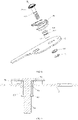
- an edge-breaking can opener including a first clamping handle 1 and a second clamping handle 2, the first clamping handle 1 and the second clamping handle 2 being connected through relative rotation by using a rivet 3, where a cutting wheel 4 and a limiting groove 5 are disposed on the first clamping handle 1, a drive wheel 6 is disposed on the second clamping handle 2, the drive wheel 6 and the cutting wheel 4 are capable of occluding each other through the limiting groove 5,
- the cutting wheel 4 includes a fixing shaft 41, a cutter wheel 42, a support wheel 43, and a round cover 44, an end of the fixing shaft 41 is aslant disposed on the first clamping handle 1, the round cover 44, the support wheel 43, and the cutter wheel 42 are separately sleeved on the fixing shaft 41 from up to bottom, an elastic piece 45 is disposed between the round cover 44 and the support wheel 43, the cutter wheel 42 is provided with a stepped groove 423, a spring plate 46 is disposed in the stepped groove 423
- the first clamping handle 1 and the second clamping handle 2 are opened, and the drive wheel 6 limits an opening range through the limiting groove 5.
- the first clamping handle 1 and the second clamping handle 2 are closed.
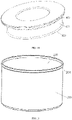
- the drive wheel 6 and the cutting wheel 4 occlude each other, to occlude the edge 201 of the can cover 200, the drive wheel 6 acts on a top edge of the can cover 200, and the cutting wheel 4 acts on the edge 201 of the can cover 200.
- a knob handle 7 is rotated, the drive wheel 6 rotates around the top edge of the can cover 200.
- the cutting wheel 4 is driven to perform cutting around the edge 201 of the can cover 200.
- the cutting wheel 4 and the drive wheel 6 can occlude each other, to directly take out the cut can cover 200.
- the can cover 200 can directly drop without being taken out by using pliers or a hand.
- An existing can opener performs rigid cutting, and thicknesses of materials of cans are inconsistent, and when a thin material is cut, a long distance between the cutter wheel 42 and the edge 201 leads to continuous cutting or a failure to cut; when a thick material is cut, a rotating portion 422 and the edge 201 occluding too tightly leads to a sharp increase in cutting force or a failure to perform cutting.
- the spring plate 46 is disposed in a stepped groove 421 of the cutter wheel 42. Because there is a movable gap between the cutter wheel 42 and the fixing shaft 41, and the gap is greater than 0.3 mm, the rotating portion 422 of the cutter wheel 42 can always come into contact with the edge 201 by means of elastic force of the spring plate 46.
- the cutter wheel 42 is enabled to approach the edge 201 by using the spring plate 46, and always act on the edge 201 to cut the edge 201.
- no sharp increase in cutting force is caused, so that force used during cutting is made lighter and stable by using the spring plate 46, thereby improving cutting quality.
- a height between the support wheel 43 and the cutter wheel 42 can be elastically adjusted by using the elastic piece 45.
- the edge 201 of a can 100 can be conveniently and quickly clamped, and the can cover 200 can be directly removed after the cutting is completed.
- the drive wheel includes an integrally formed gear disk 61 and a rotating shaft 62, the rotating shaft 62 is further provided with a straight groove 621, the straight groove 621 is provided with a card 65, the gear disk 61 includes a tray gear 611 and a helical gear 612, the tray gear 611 and the helical gear 612 are aslant disposed, and a round angle 613 is provided between the tray gear and the helical gear.
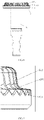
- the gear disk 61 of the existing can opener includes the tray gear 611 and a spur gear, and the tray gear 611 and the spur gear are disposed in a manner of being perpendicular to each other, when the cutting wheel 4 cuts the can cover 200, a cutting location is relatively deep, and a height for cutting the edge 201 is 1.0 mm to 1.2 mm. After the cutting, a part of the can cover 200 is still stuck in the can body 100, cannot be peeled off by hand, and still needs to be clamped out with pliers.
- the gear disk 61 uses an inclined design of the tray gear 611 and the helical gear 612, and a round angle 613 is disposed between the tray gear 611 and the helical gear 612, during cutting, a location at which the cutting wheel 4 cuts the can cover 200 is relatively shallow, and a height of the cut edge 201 is 0.6 mm to 0.8 mm. After the cutting, the can cover 200 can be completely separated from the can body 100, which improves cutting quality.
- the cutter wheel 42 includes an integrally formed rotating portion 422 and a cutter portion 423 protruding outwards, the cutter portion 423 is disposed at a lower portion of the cutter wheel 42, a boss portion 431 protruding outwards is disposed on the support wheel 43, and the boss portion 431 is disposed at a lower portion of the support wheel 43.
- a protrusion portion 400 is further disposed at an upper portion of the rotating portion 422 of the existing cutter wheel 42, the cutter wheel 42 can cut the edge 201 of the can cover 200 only with a certain height.
- the edge 201 of the can cover 200 cannot be occluded.
- the protrusion portion 400 of the rotating portion 422 is canceled, and the edge 201 of the can cover 200 is directly occluded by using the cutter portion 423 and the drive wheel 6.
- the support wheel 43 is elastically adjusted by using an elastic piece 45, to make a height between the cutter portion 423 and the boss portion 431 match a height of the edge 201, so that this product can cut the edge 201 of the can cover 200 with different heights.
- the cut can cover 200 can be further directly clamped and taken out based on a distance between the cutter portion 423 and the gear disk 61, without pliers or a hand.
- the drive wheel 6 can be directly separated from the cutting wheel 4, and the can cover 200 can directly drop, thereby improving a practical function of this product.
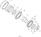
- the cutting wheel 4 further includes a cutter wheel washer 47 and a gear washer 48.
- the cutter wheel washer 47 is sleeved on the fixing shaft 41, and is disposed between the cutter wheel 42 and the first clamping handle 1
- a spring plate stopper 471 is disposed on a surface, of the cutter wheel washer 47, adjacent to the cutter wheel 42, the spring plate stopper 471 cooperates with the opening 461
- a fixing block 472 for fixing is disposed on the other surface of the cutter wheel washer 47
- the gear washer 48 is sleeved on the fixing shaft 41, and is disposed above the cutter wheel 42 and inside the support wheel 43.
- the cutter wheel washer 47 and the gear washer 48 are disposed on the fixing shaft 41, and the cutter wheel washer 47 is fixed on the first clamping handle 1 by using the fixing block 472, so that when the cutter wheel 42 is rotating, the cutter wheel washer 47 does not follow the cutter wheel to rotate.
- the spring plate stopper 471 on the cutter wheel washer 47 acts on the spring plate 46, and the opening 464 of the spring plate 46 is stuck on the spring plate stopper 471, so that the spring plate 46 acts on the cutter wheel 42.
- a fixing sleeve 63 is further disposed on the second clamping handle 2
- a step 631 protruding outwards and an oblique groove 632 are separately disposed on the fixing sleeve 63
- a rivet sleeve 64 is sleeved on the oblique groove 632
- the fixing sleeve 63 passes through the second clamping handle 2 by using the step 631 and the rivet sleeve 64
- the rotating shaft 62 passes through the fixing sleeve 63 by using the gear disk 61 and the card 65
- a surface cover 66 further covers the fixing sleeve 63
- the surface cover is disposed between the gear disk 61 and the first clamping handle 1
- a knob handle 7 is further disposed at the other end of the rotating shaft 62.
- the fixing sleeve 63 passes through the second clamping handle 2, and comes into contact with a top surface of the second clamping handle 2 by using a lower step surface of the step 631, and acts on a bottom surface of the second clamping handle 2 by using the straight groove 632 and the rivet sleeve 64, so that the fixing sleeve 63 and the second clamping handle 2 keep a fixed connection.
- an end of the rotating shaft 62 with the gear disk 61 is disposed at one end of the fixing sleeve 63, and the other end of the rotating shaft 62 passes through the fixing sleeve 63, and is connected to the fixing sleeve 63 through cooperation between the straight groove 621 and a card 65.
- the knob handle 7 is disposed at the end of the rotating shaft 62.
- the knob handle 7 can facilitate rotating the gear disk 61.
- the connection between the fixing sleeve 63 and the second clamping handle 2 is made firmer through the step 631 and the rivet sleeve 64, the connection between this structure makes the costs low, and upper and lower locations of the rotating shaft 62 are not offset by using the gear disk 61 and the card 65, thereby ensuring cooperation between the gear disk 61 and the cutting wheel 4.
- the cutter wheel 42 is made of a 1.4116 stainless steel material
- the drive wheel 6, the cutter wheel washer 47, the gear washer 48, and the fixing sleeve 63 are all made of a 420J2 stainless steel material
- the round cover 44 is made of a 304 stainless steel material. Because 420J2 stainless steel has good wear resistance and corrosion resistance with high hardness and desirable rigidity, and German 1.4116 stainless steel has higher hardness and better toughness, a cutting service life of the cutter wheel 42 can be increased, thereby reducing abrasion wear of the cutter wheel 42, the drive wheel 6, the cutter wheel washer 47, the gear washer 48, and the fixing sleeve 63.
- the round cover 44 is made of 304 stainless steel.
- the 304 stainless steel has characteristics of desirable anti-rust performance, desirable polishing performance, and the like, can make the can opener overall beautiful, and improve use safety of the can opener, thereby increasing a service life of the edge-breaking can opener.
Landscapes
- Engineering & Computer Science (AREA)
- Mechanical Engineering (AREA)
- Devices For Opening Bottles Or Cans (AREA)
Applications Claiming Priority (2)
| Application Number | Priority Date | Filing Date | Title |
|---|---|---|---|
| CN201911205898.5A CN111646408B (zh) | 2019-11-29 | 2019-11-29 | 一种开边开罐器 |
| PCT/CN2019/122278 WO2021103029A1 (zh) | 2019-11-29 | 2019-11-30 | 一种开边开罐器 |
Publications (2)
| Publication Number | Publication Date |
|---|---|
| EP4032849A1 true EP4032849A1 (de) | 2022-07-27 |
| EP4032849A4 EP4032849A4 (de) | 2023-11-29 |
Family
ID=72352382
Family Applications (1)
| Application Number | Title | Priority Date | Filing Date |
|---|---|---|---|
| EP19954354.7A Withdrawn EP4032849A4 (de) | 2019-11-29 | 2019-11-30 | Flanschschneide-dosenöffner |
Country Status (7)
| Country | Link |
|---|---|
| US (1) | US10981767B1 (de) |
| EP (1) | EP4032849A4 (de) |
| JP (1) | JP7291296B2 (de) |
| CN (1) | CN111646408B (de) |
| DE (1) | DE112019001247B4 (de) |
| GB (1) | GB2603713B (de) |
| WO (1) | WO2021103029A1 (de) |
Families Citing this family (3)
| Publication number | Priority date | Publication date | Assignee | Title |
|---|---|---|---|---|
| CN113526430B (zh) * | 2021-08-12 | 2023-03-10 | 珠海横琴鑫润智能制造有限公司 | 开罐器及其控制方法 |
| CA3211202A1 (en) * | 2022-09-07 | 2024-03-07 | Smart Skin Technologies Inc. | Can cutting device |
| CN119407854B (zh) * | 2024-12-02 | 2025-11-11 | 江西赣电电气有限公司 | 一种变压器绝缘纸圈圆剪装置 |
Family Cites Families (23)
| Publication number | Priority date | Publication date | Assignee | Title |
|---|---|---|---|---|
| US4633589A (en) * | 1984-10-26 | 1987-01-06 | R. Rick Rodig | Can opener |
| CN2118067U (zh) * | 1990-12-07 | 1992-10-07 | 川北电子工业公司广明无线电厂 | 罐筒开割器 |
| GB9113022D0 (en) * | 1991-06-17 | 1991-08-07 | Sentech Enterprise Limited | Improvements in can openers |
| CN2111948U (zh) * | 1991-10-05 | 1992-08-05 | 上饶县标准件厂 | 多功能开罐器 |
| WO1996029276A1 (en) * | 1994-01-20 | 1996-09-26 | William Levene Limited | Can opener |
| US5651183A (en) * | 1995-04-28 | 1997-07-29 | Hydro-Thermal Corporation | Portable fiber drum chime remover |
| CN2303827Y (zh) * | 1997-05-09 | 1999-01-13 | 千农实业有限公司 | 开罐器 |
| AU737482B2 (en) * | 1998-03-06 | 2001-08-23 | Union Lucky Industrial Limited | Can opener |
| GB2367801B (en) | 2000-09-21 | 2004-04-14 | Leslie Peter Stuart Wilson | Can opener |
| GB2383572B (en) | 2001-12-28 | 2003-11-05 | Shun So | Can opener |
| TW532384U (en) * | 2002-06-06 | 2003-05-11 | Alston Technologies Dev Co Ltd | Can opener with two pivotally connected levers operable in laid down position |
| DE202004007523U1 (de) * | 2004-05-11 | 2005-09-22 | Emsa Werke Wulf Gmbh & Co Kg | Dosenöffner |
| GB2418657B (en) * | 2004-09-30 | 2007-01-03 | Kwok Kuen So | Can opener |
| US20060101652A1 (en) * | 2004-11-12 | 2006-05-18 | Shun So | Self gripping can opener |
| GB2420108B (en) * | 2004-11-12 | 2007-01-03 | Union Lucky Ind Ltd | Self gripping can opener |
| US20070033815A1 (en) * | 2005-08-09 | 2007-02-15 | Lazaroff William J | Adjustable can opener |
| US7596874B2 (en) * | 2005-12-12 | 2009-10-06 | Daka Research Inc. | Mechanism for can opener |
| US7784190B2 (en) * | 2007-05-22 | 2010-08-31 | Union Lucky Industrial Limited | Can opener |
| US20140290077A1 (en) * | 2013-04-01 | 2014-10-02 | Jay Paulson | Seal Cutter |
| FR3006302B1 (fr) | 2013-05-29 | 2015-10-16 | Excellence Innovation Ltd | Ouvre-boite manuel du type a arbre rotatif muni d'une molette et d'une poignee de manoeuvre |
| GB201311135D0 (en) * | 2013-06-21 | 2013-08-07 | Kalogroulis Alexander | Can opener mechanism |
| US20150239721A1 (en) | 2014-02-21 | 2015-08-27 | Joseph A. Bechtold | Power operable can opener |
| CN211141495U (zh) * | 2019-11-29 | 2020-07-31 | 罗功平 | 一种开边开罐器 |
-
2019
- 2019-11-29 CN CN201911205898.5A patent/CN111646408B/zh active Active
- 2019-11-30 EP EP19954354.7A patent/EP4032849A4/de not_active Withdrawn
- 2019-11-30 US US16/980,306 patent/US10981767B1/en active Active
- 2019-11-30 JP JP2022530680A patent/JP7291296B2/ja active Active
- 2019-11-30 DE DE112019001247.9T patent/DE112019001247B4/de active Active
- 2019-11-30 WO PCT/CN2019/122278 patent/WO2021103029A1/zh not_active Ceased
- 2019-11-30 GB GB2205875.4A patent/GB2603713B/en active Active
Also Published As
| Publication number | Publication date |
|---|---|
| DE112019001247B4 (de) | 2023-10-05 |
| US10981767B1 (en) | 2021-04-20 |
| JP7291296B2 (ja) | 2023-06-14 |
| DE112019001247T5 (de) | 2021-08-12 |
| GB202205875D0 (en) | 2022-06-08 |
| WO2021103029A1 (zh) | 2021-06-03 |
| GB2603713B (en) | 2023-09-13 |
| GB2603713A (en) | 2022-08-10 |
| CN111646408B (zh) | 2025-01-07 |
| JP2023503156A (ja) | 2023-01-26 |
| EP4032849A4 (de) | 2023-11-29 |
| CN111646408A (zh) | 2020-09-11 |
Similar Documents
| Publication | Publication Date | Title |
|---|---|---|
| US10981767B1 (en) | Edge-breaking can opener | |
| KR20120089641A (ko) | 절단장치 | |
| EP2098340A1 (de) | Rotationsschneider | |
| US4213215A (en) | Container opener | |
| CN101357746B (zh) | 罐头开启器 | |
| WO2019055892A1 (en) | CAMPING UTENSILS KIT | |
| CA1258575A (en) | Can-openers | |
| US2897589A (en) | Can opening and knife sharpening device | |
| EP1323666B1 (de) | Dosenöffner | |
| US2562842A (en) | Bottle cap lifter | |
| CN211141495U (zh) | 一种开边开罐器 | |
| US3423825A (en) | Can opener | |
| US2804683A (en) | Can opener | |
| US3909860A (en) | Combination can-opener tool | |
| US2190940A (en) | Can opener | |
| US2236342A (en) | Jar wrench | |
| US1813620A (en) | Can opener | |
| US1397537A (en) | Can-opener | |
| US2215492A (en) | Ice pick | |
| US2171658A (en) | Can opener | |
| US20060085991A1 (en) | Can opener | |
| US1863531A (en) | Can opener | |
| US2718055A (en) | Can opener | |
| US3224018A (en) | Device for kitchen tools and the like | |
| US2946362A (en) | Food slicer blade engagement |
Legal Events
| Date | Code | Title | Description |
|---|---|---|---|
| STAA | Information on the status of an ep patent application or granted ep patent |
Free format text: STATUS: THE INTERNATIONAL PUBLICATION HAS BEEN MADE |
|
| PUAI | Public reference made under article 153(3) epc to a published international application that has entered the european phase |
Free format text: ORIGINAL CODE: 0009012 |
|
| STAA | Information on the status of an ep patent application or granted ep patent |
Free format text: STATUS: REQUEST FOR EXAMINATION WAS MADE |
|
| 17P | Request for examination filed |
Effective date: 20220422 |
|
| AK | Designated contracting states |
Kind code of ref document: A1 Designated state(s): AL AT BE BG CH CY CZ DE DK EE ES FI FR GB GR HR HU IE IS IT LI LT LU LV MC MK MT NL NO PL PT RO RS SE SI SK SM TR |
|
| DAV | Request for validation of the european patent (deleted) | ||
| DAX | Request for extension of the european patent (deleted) | ||
| P01 | Opt-out of the competence of the unified patent court (upc) registered |
Effective date: 20230307 |
|
| A4 | Supplementary search report drawn up and despatched |
Effective date: 20231027 |
|
| RIC1 | Information provided on ipc code assigned before grant |
Ipc: B67B 7/70 20060101ALI20231023BHEP Ipc: B67B 7/16 20060101ALI20231023BHEP Ipc: B67B 7/46 20060101AFI20231023BHEP |
|
| STAA | Information on the status of an ep patent application or granted ep patent |
Free format text: STATUS: THE APPLICATION IS DEEMED TO BE WITHDRAWN |
|
| 18D | Application deemed to be withdrawn |
Effective date: 20240515 |