EP4033042A1 - Dispositif de fixation d'un évier - Google Patents
Dispositif de fixation d'un évier Download PDFInfo
- Publication number
- EP4033042A1 EP4033042A1 EP22152736.9A EP22152736A EP4033042A1 EP 4033042 A1 EP4033042 A1 EP 4033042A1 EP 22152736 A EP22152736 A EP 22152736A EP 4033042 A1 EP4033042 A1 EP 4033042A1
- Authority
- EP
- European Patent Office
- Prior art keywords
- guide body
- sink
- anchoring
- plane
- retaining
- Prior art date
- Legal status (The legal status is an assumption and is not a legal conclusion. Google has not performed a legal analysis and makes no representation as to the accuracy of the status listed.)
- Pending
Links
- 238000004873 anchoring Methods 0.000 claims abstract description 44
- 230000008878 coupling Effects 0.000 claims description 5
- 238000010168 coupling process Methods 0.000 claims description 5
- 238000005859 coupling reaction Methods 0.000 claims description 5
- 230000001105 regulatory effect Effects 0.000 abstract description 3
- 238000009434 installation Methods 0.000 description 3
- 239000000463 material Substances 0.000 description 3
- 239000000853 adhesive Substances 0.000 description 2
- 230000001070 adhesive effect Effects 0.000 description 2
- 239000000919 ceramic Substances 0.000 description 2
- 239000002131 composite material Substances 0.000 description 2
- 238000004851 dishwashing Methods 0.000 description 2
- 239000003292 glue Substances 0.000 description 2
- 239000002184 metal Substances 0.000 description 2
- 229910001220 stainless steel Inorganic materials 0.000 description 2
- 239000010935 stainless steel Substances 0.000 description 2
- 239000004575 stone Substances 0.000 description 2
- 238000006243 chemical reaction Methods 0.000 description 1
- 230000001419 dependent effect Effects 0.000 description 1
- 238000000605 extraction Methods 0.000 description 1
- 238000003780 insertion Methods 0.000 description 1
- 230000037431 insertion Effects 0.000 description 1
- 238000000034 method Methods 0.000 description 1
- 238000003801 milling Methods 0.000 description 1
- 238000000465 moulding Methods 0.000 description 1
- 238000004080 punching Methods 0.000 description 1
- 229920005989 resin Polymers 0.000 description 1
- 239000011347 resin Substances 0.000 description 1
- 239000007787 solid Substances 0.000 description 1
- 229920003002 synthetic resin Polymers 0.000 description 1
- 239000000057 synthetic resin Substances 0.000 description 1
Images


Classifications
-
- E—FIXED CONSTRUCTIONS
- E03—WATER SUPPLY; SEWERAGE
- E03C—DOMESTIC PLUMBING INSTALLATIONS FOR FRESH WATER OR WASTE WATER; SINKS
- E03C1/00—Domestic plumbing installations for fresh water or waste water; Sinks
- E03C1/12—Plumbing installations for waste water; Basins or fountains connected thereto; Sinks
- E03C1/32—Holders or supports for basins
- E03C1/33—Fastening sinks or basins in an apertured support
-
- E—FIXED CONSTRUCTIONS
- E03—WATER SUPPLY; SEWERAGE
- E03C—DOMESTIC PLUMBING INSTALLATIONS FOR FRESH WATER OR WASTE WATER; SINKS
- E03C1/00—Domestic plumbing installations for fresh water or waste water; Sinks
- E03C1/12—Plumbing installations for waste water; Basins or fountains connected thereto; Sinks
- E03C1/32—Holders or supports for basins
- E03C1/33—Fastening sinks or basins in an apertured support
- E03C1/335—Fastening sinks or basins in an apertured support the fastening means comprising a screw
Definitions
- the present invention relates to a device for fixing a sink in an opening of a plane, as well as to a sink fixable in the opening by means of a plurality of such devices.
- the term “sink” refers to generic washbasins used in home and/or restaurant kitchens for washing dishes or for sanitary purposes, made of waterproof material, such as ceramic, stainless steel, natural or sintered stone, synthetic resins or composite material.
- known devices comprise a first body fixable to a lower surface of a sink by means of an anchoring means and a second body, slidingly constrained to the first body, which has a retaining element configured to abut the lower surface of the plane, commonly called “top”, the latter having an opening for housing the sink.
- the anchoring means is typically with expansion plugs and is housed in respective seats arranged on the lower surface of the sink.
- the fixing devices further comprise adjusting and clamping means configured to cause the second body to slide with respect to the first body, in such a way as to apply a clamping force adapted to stabilize the sink and make it as adhering as possible to the upper surface of the plane.
- the first body by means of the anchoring means, exerts a traction action on the lower surface of the sink while the second body, by means of the retaining element, exerts a thrust action on the lower surface of the plane.
- the thrust action on the plane generates a traction reaction on the anchoring means constrained to the sink.
- the clamping force exerted by the device on the sink is substantially parallel and concordant with the extraction direction of the anchoring means and therefore it is possible that, while clamping the device, the anchoring means comes out from their respective seats.
- a further problem concerns the versatility of use of the fixing devices.
- known devices are configured to operate in a determined dimensional range defined by the thickness of the plane and of the sink.
- the operator is forced to interpose a thickness between the lower surface of the plane and the retaining element of the fixing device, making the operations for laying and installing the sink more complex.
- the technical task of the present invention is to propose a device for fixing a sink in an opening of a plane capable of overcoming the drawbacks of the prior art. It is also a technical task of the present invention to make available a sink fixable in an opening of a plane by means of one or more fixing devices in accordance with the invention. In particular, an object of the present invention is to make available a device for fixing a sink which is extremely versatile.
- a further object of the present invention is to propose a device for fixing a sink which is sturdy and capable of guaranteeing a stable fixing of the sink.
- Another object of the present invention is to realize a device for fixing a sink capable of facilitating and optimising the operations for laying and installing the sink itself.
- FIGS 1 , 2 , 3A and 3B illustrate a device 1 for fixing a sink "L” in an opening of a plane "P", in accordance with the present invention.
- the device 1 for fixing a sink finds application in the fitting of generic sinks used in home and restaurant kitchens for washing dishes and/or for sanitary purposes.
- the device 1 can be used with sinks made of various materials, for example ceramic, stainless steel, natural or sintered stone. Even more advantageously, the device 1 according to the invention finds particular and effective use with sinks made of resin or composite material.
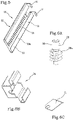
- the device 1 comprises a guide body 10 with an elongated conformation and which extends along a direction of extension "X".
- the device 1 comprises an anchoring body 20, constrained or constrainable to a first side 11 of the guide body 10, and a retaining body 30, slidingly applied to the guide body 10 along the direction of extension "X" thereof.
- the retaining body 30 is operationally arranged on a second side 12 of the guide body 10 opposite the first side 11.
- the guide body 10 is plate-like or in any case has a longitudinal dimension, along the direction of extension "X", which is predominant with respect to the width and thickness thereof.
- the guide body 10 preferably comprises a metal sheet.
- the anchoring body 20, constrained or constrainable to the first side 11 of the guide body 10 is equipped with an anchoring means 21 for the stable fixing to a lower surface of a sink "L".
- the term “constrained” means that the anchoring body 20 is irreversibly coupled to the guide body 10.
- the term “constrainable” means that the anchoring body 20 can be reversibly coupled to the guide body 10.
- the anchoring means 21 comprises at least one expansion plug 21a obtained integrally with the anchoring body 20 and configured to be inserted into at least one respective receiving seat "L2" obtained on the lower surface of the sink “L” ( figure 3 ).
- the anchoring body is equipped with two expansion plugs 21a.
- the at least one expansion plug 21a is configured to house a respective expander 21b.
- the expander 21b can have cylindrical or wedge conformation, with a smooth or corrugated surface and can be inserted slidingly into the respective expansion plug 21a by means of a certain pressure.
- the expander 21b can be a cylindrical threaded member which can be clamped inside the expansion plug 21a.
- the anchoring means 21 and the seat “L2" can comprise threaded elements, which are reciprocally and reversibly constrainable.
- the anchoring body 20 has a sliding portion 22 engaged or engageable with a respective guide portion 13 of the guide body 10 such that the position of the anchoring body 20 can be adjusted and/or regulated along the guide body 10.
- the sliding of the sliding portion 22 inside the guide portion 13 occurs by slipping, so as to define a substantially stable positioning of the anchoring body 20 along the guide body 10.
- the possibility of moving and regulating the anchoring body 20 along the guide body 10 together with the possibility of moving and fixing the retaining body 30 along the guide body 10 allows the device 1 to be used in a large dimensional range of thicknesses of the plane "P" and/or of the sink "L".
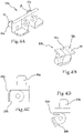
- the anchoring body 20 comprises a first component 20a that is stably applicable to the sink "L".
- the sliding portion 22 comprises a second component 20b that is slidingly applicable to the guide body 10.
- the first and second component 20a, 20b are reciprocally hinged or hingeable, so as to be tiltable respectively around a tilt axis "Y" that is transverse, preferably perpendicular, to the direction of extension "X" of the guide body 10.
- this degree of freedom allows to vary the orientation of the guide body 10, and therefore of the retaining body 30 constrained to the guide body 10, with respect to the sink "L” itself.
- the guide body 10 can be inclined with respect to the sink “L".
- the retaining element 31 in turn assumes a position away from the encumbrance of the plane "P" (or from a projection thereof in vertical direction), thus allowing an easy insertion of the sink "L” inside the opening of the plane "P” itself.
- the aforementioned degree of freedom (tilting) allows the device 1 to be adapted to a multiplicity of conformations of the sink "L” and/or of the plane "P".
- the device 1 can comprise recall means 22d configured to promote a reciprocal movement between the first and the second component 20a, 20b.
- the recall means 22d is preferably interposed between the first and the second component 20a, 20b.
- the recall means 22d promotes a reciprocal movement between the first and the second component 20a, 20b around the tilt axis "Y" in order to orient, in use, the guide body 10 so that it is not vertical and does not hinder the operations for inserting the sink "L” inside the opening of the plane "P". In other words, once the device 1 is fixed to the sink "L", the recall means 22d prevents the guide body 10 from assuming a vertical orientation.
- the recall means 22d is illustrated by way of example in figures 4C and 4D .
- the second component 20b has one or more elastically deformable elements, preferably fins, configured to abut the first component 20a.
- the device 1 can comprise one or more torsional springs interposed between the first and the second component 20a, 20b.
- the sliding portion 22 comprises a sliding slide 22a and the guide portion 13 of the guide body 10 is defined by folded edges 13a of the guide body 10.
- the folded edges 13a are made in such a way as to be parallel to the direction of extension "X" and are adapted to constrain the sliding slide 22a in a translation motion parallel to the aforementioned direction of extension "X".
- the movement of the sliding portion 22 inside the guide portion 13 occurs by sliding.
- the retaining body 30 is slidable on the guide body 10 along the direction of extension "X" and is operationally arranged on the second side 12 of the guide body 10.
- the retaining body 30 comprises an adjusting and clamping means 32 adapted to cause a controlled movement and stable positioning of the retaining body 30 along the guide body 10.
- the guide body 10 has a plurality of transverse openings 15, or preferably through grooves, which substantially define a rack.
- the guide body 10 has a series of substantially identical and equidistant transverse seats made along the guide body 10.
- these transverse openings 15 can be made by punching the guide body 10, if the latter is made of metal sheet, or by moulding, if the guide body is made of plastic material.
- the adjusting and clamping means 32 of the retaining body 30 comprises a threaded member 33 associated or associable with the rack by means of a respective screw propeller 33a.
- the threaded member 33 is movable in rotation around a respective axis of rotation "Z", parallel to the direction of extension "X", such that a rotation of the threaded member 33 corresponds to a predetermined translation of the threaded member 33 along the axis of rotation "Z" (and therefore along the direction of extension "X").
- the threaded member 33 can advantageously have a head portion provided with an engagement seat for a screwdriver adapted to facilitate the movement of the threaded member 33.
- the threaded member 33 can have a head sized such that it can be grasped with a tool, for example pliers, or by hand by an operator.
- the anchoring body 20 can have a recess 22c in such a way that the screw propeller 33a and the anchoring body 20 do not hinder each other.
- the retaining body 30 further comprises a containing element 34 for containing the threaded member 33, slidingly constrained to the guide body 10 and adapted to maintain the threaded member 33 adhering to the guide body 10.
- the containing element 34 has a pair of coupling fins 34a configured to constrain the containing body 34 to the edge 13 of the guide body 10, allowing it to slide at the same time.
- the retaining body 30 comprises a retaining element 31 configured, in use, to abut against a lower surface of the plane "P".
- the retaining element 31 comprises a plate 31a constrained to the threaded member 33 and/or to the containing element 34 and oriented, in use, transversely to the direction of extension "X" to define a shoulder for abutting or coupling against a surface of the plane "P".
- the retaining element 31 is constrained to the threaded member 33 in a rotatable way around its axis of rotation "Z" between an engagement configuration, suitable for coupling or stopping against a surface of the plane "P", and a rotated disengagement configuration, suitable for a step of fitting or dismantling the sink "L".
- the retaining element 31 can be advantageously rotated in such a way as to limit the encumbrance of the device 1. This feature is particularly advantageous in the operations for laying and installing the sink "L", and in particular in the step of inserting the sink "L” inside the opening of the plane "P".
- the constraint between the retaining element 31 and the threaded member 33 allows a certain play of the retaining element 31, it is easily adaptable to the conformation of the lower surface of the plane "P", especially in the case in which, once installed, the device 1 settles with the direction of extension "X" of the guide body 10 that is not perfectly perpendicular to the ground.
- the device 1 comprises an auxiliary retaining element 14, fixed or obtained integrally in an end portion of the guide body 10 and configured to couple, in use, in a respective shoulder "L1" of the lower surface of the sink "L".
- the auxiliary retaining element 14 provides a stable clamping of the guide body 10 and of the anchoring body 20 to the sink "L".
- the auxiliary retaining element 14 confers an "L" or "C"-shaped termination to the guide body 10.
- this characteristic allows to at least partially, preferably integrally, discharge the traction force that is exerted by the adjusting and clamping means 32 on the anchoring means 21, preventing the latter from coming out of their respective seats “L2" and therefore avoiding the use of glues and adhesives during the installation of the sink "L”.
- the auxiliary retaining element 14 works substantially like a harpoon.
- the auxiliary retaining element 14 can be disengaged in the opposite direction to the direction of the traction force applied by the device 1 on the sink "L”.
- the guide body 10 has a spacing portion 16, associated with or obtained in the end portion of the guide body 10 and configured, in use, to abut against a frontal edge of the plane "P".
- the spacing element 16 extends away from the second side 12 of the guide body 10 to cause a spacing of the frontal edge of the plane "P" with respect to the second side 12 of the guide body 10.
- this spacing element 16 by means of the thrust exerted by the front surface of the plane "P", allows to keep the auxiliary retaining element 14 adhering to the shoulder "L1" in the optimal operating position, during the laying and installation operations, and in particular during the operations for clamping the adjusting and clamping means 32.
- this spacing element 16 ensures an optimal positioning of the sink "L” inside the opening of the plane "P".
- the sink "L” is prepared. Subsequently, the expansion plugs 21a are inserted into the respective seats “L2" of the lower surface of the sink “L” and are stably constrained by means of the expanders 21b.
- the sink "L” is housed in the opening of the plane "P".
- the guide body 10 of the one or more devices 1 can be inclined with respect to the sink “L” using the tilt axis "Y".
- the recall means 22d automatically moves the second component 20b with respect to the first component 20a in such a way as to incline the guide body 10.
- the retaining member 31 can be switched to the rotated, disengagement configuration.
- the present invention also relates to a sink "L” insertable into an opening of a plane “P” and fixable in this opening by means of one or more of the above-described fixing devices 1.
- the sink "L” has an upper surface, defining a containment volume, and a lower surface, opposite the upper surface.
- the lower surface has at least one receiving seat “L2” adapted to house the anchoring means 21 and at least one shoulder “L1” adapted to house the auxiliary retaining element 14.
- the shoulder "L1” it can be made in one piece with the sink "L” or it can be obtained in a subsequent step, for example by milling.
- the present invention reaches the set objects.
- a fixing device according to the invention is extremely versatile. Furthermore, thanks to the possibility of moving the anchoring body 20 and the retaining body 30 along the guide body 10, the fixing device according to the invention is able to operate on a wide range of thicknesses of the plane "P" and/or of the sink "L".
- the fixing device is extremely robust and is able to guarantee a stable fixing of the sink, as well as to facilitate and optimise the operations for laying and installing the sink, especially due to the tilting movement of the guide body 10.
- the auxiliary retaining element 14 ensures a solid and robust constraint of the device 1 to the sink "L". Consequently, the device according to the invention allows to effectively clamp the retaining element 31 on the lower surface of the plane "P", so that the sink "L” adheres perfectly to the plane "P".
Landscapes
- Engineering & Computer Science (AREA)
- Environmental & Geological Engineering (AREA)
- Health & Medical Sciences (AREA)
- Life Sciences & Earth Sciences (AREA)
- Hydrology & Water Resources (AREA)
- Public Health (AREA)
- Water Supply & Treatment (AREA)
- Surgical Instruments (AREA)
- Gripping Jigs, Holding Jigs, And Positioning Jigs (AREA)
- Telephone Function (AREA)
- Connection Of Plates (AREA)
Applications Claiming Priority (1)
| Application Number | Priority Date | Filing Date | Title |
|---|---|---|---|
| IT102021000001490A IT202100001490A1 (it) | 2021-01-26 | 2021-01-26 | Dispositivo per il fissaggio di un lavello |
Publications (1)
| Publication Number | Publication Date |
|---|---|
| EP4033042A1 true EP4033042A1 (fr) | 2022-07-27 |
Family
ID=75439245
Family Applications (1)
| Application Number | Title | Priority Date | Filing Date |
|---|---|---|---|
| EP22152736.9A Pending EP4033042A1 (fr) | 2021-01-26 | 2022-01-21 | Dispositif de fixation d'un évier |
Country Status (2)
| Country | Link |
|---|---|
| EP (1) | EP4033042A1 (fr) |
| IT (1) | IT202100001490A1 (fr) |
Cited By (1)
| Publication number | Priority date | Publication date | Assignee | Title |
|---|---|---|---|---|
| IT202200021264A1 (it) * | 2022-10-14 | 2024-04-14 | Marcolini Giuseppe S R L | Gancio di fissaggio di lavelli o similari a piani di base |
Citations (6)
| Publication number | Priority date | Publication date | Assignee | Title |
|---|---|---|---|---|
| US3008150A (en) * | 1958-12-24 | 1961-11-14 | Lyon Inc | Sink retaining means |
| US3034141A (en) * | 1959-07-17 | 1962-05-15 | Lyon Inc | Sink retaining structure |
| US3365732A (en) * | 1965-09-27 | 1968-01-30 | Verson Mfg Co | Self-rimming sink mounting |
| ES2275479T3 (es) * | 1999-09-24 | 2007-06-16 | Lisi Automotive Rapid | Dispositivo de fijacion de un elemento encastrable en una abertura de colocacion de una placa de soporte. |
| ES2316688T3 (es) * | 2002-11-06 | 2009-04-16 | Blanco Gmbh + Co Kg | Dispositivo de sujecion para sujetar una griferia sobre un fregadero, que esta dispuesto sobre una encimera. |
| CN111719650A (zh) * | 2019-03-19 | 2020-09-29 | 肖克有限公司 | 固定装置 |
-
2021
- 2021-01-26 IT IT102021000001490A patent/IT202100001490A1/it unknown
-
2022
- 2022-01-21 EP EP22152736.9A patent/EP4033042A1/fr active Pending
Patent Citations (6)
| Publication number | Priority date | Publication date | Assignee | Title |
|---|---|---|---|---|
| US3008150A (en) * | 1958-12-24 | 1961-11-14 | Lyon Inc | Sink retaining means |
| US3034141A (en) * | 1959-07-17 | 1962-05-15 | Lyon Inc | Sink retaining structure |
| US3365732A (en) * | 1965-09-27 | 1968-01-30 | Verson Mfg Co | Self-rimming sink mounting |
| ES2275479T3 (es) * | 1999-09-24 | 2007-06-16 | Lisi Automotive Rapid | Dispositivo de fijacion de un elemento encastrable en una abertura de colocacion de una placa de soporte. |
| ES2316688T3 (es) * | 2002-11-06 | 2009-04-16 | Blanco Gmbh + Co Kg | Dispositivo de sujecion para sujetar una griferia sobre un fregadero, que esta dispuesto sobre una encimera. |
| CN111719650A (zh) * | 2019-03-19 | 2020-09-29 | 肖克有限公司 | 固定装置 |
Cited By (2)
| Publication number | Priority date | Publication date | Assignee | Title |
|---|---|---|---|---|
| IT202200021264A1 (it) * | 2022-10-14 | 2024-04-14 | Marcolini Giuseppe S R L | Gancio di fissaggio di lavelli o similari a piani di base |
| WO2024079715A1 (fr) * | 2022-10-14 | 2024-04-18 | Marcolini Giuseppe S.r.l. | Crochet de fixation pour éviers ou autres articles similaires sur des surfaces de base |
Also Published As
| Publication number | Publication date |
|---|---|
| IT202100001490A1 (it) | 2022-07-26 |
Similar Documents
| Publication | Publication Date | Title |
|---|---|---|
| EP0525907B1 (fr) | Dispositif de fixation d'un boîtier dans une cavité, en particulier pour les armatures encastrées dans des panneaux | |
| EP2398625B1 (fr) | Dispositif de serrage pour attacher un élément de bord sur le haut d'un banc, le haut d'une table ou similaire | |
| KR101516060B1 (ko) | 광학 장치용 퀵 클램프 장치 | |
| EP1470340B1 (fr) | Fixation de raccords de tuyau | |
| US8672286B2 (en) | Adjustable wall hanger | |
| US20080310913A1 (en) | Fixture for attaching a profile rail to another component | |
| US12491610B2 (en) | Fastener setting tool | |
| JP2008544866A5 (fr) | ||
| EP3152448B1 (fr) | Connecteur pour connecter des éléments à section profilée | |
| CA2890936A1 (fr) | Pince pour dispositifs fixes sur une surface | |
| US12297689B2 (en) | Device and method for securing frames | |
| US12017318B1 (en) | Accessory mounting system for connection to a work component having an elongated T-shaped slot | |
| IT202100001490A1 (it) | Dispositivo per il fissaggio di un lavello | |
| ES2953961T3 (es) | Unidad de montaje con al menos un riel de montaje y con al menos una abrazadera de sujeción | |
| EP0165621A2 (fr) | Bride de blocage pour dispositifs de fixation | |
| EP3647609B1 (fr) | Fixation de canal à engagement flexible de la bride de canal | |
| EP0469668B1 (fr) | Assemblage pour pieds de meubles | |
| EP2336474A1 (fr) | Pince | |
| JP4954845B2 (ja) | 手工具用ホルダー | |
| EP3587720A1 (fr) | Ensemble de finition de révélation et procédé de finition d'une révélation à l'aide de panneaux de révélation | |
| CN215880527U (zh) | 便于调节的夹具 | |
| CA3058126A1 (fr) | Pince de fixation pour evier | |
| US20200215669A1 (en) | Adjusting and Positioning Device for Wooden Boards | |
| CN114728566B (zh) | 具有经简化固定的窗滑动引导件 | |
| EP4726138A1 (fr) | Support de baguette d'angle |
Legal Events
| Date | Code | Title | Description |
|---|---|---|---|
| PUAI | Public reference made under article 153(3) epc to a published international application that has entered the european phase |
Free format text: ORIGINAL CODE: 0009012 |
|
| STAA | Information on the status of an ep patent application or granted ep patent |
Free format text: STATUS: THE APPLICATION HAS BEEN PUBLISHED |
|
| AK | Designated contracting states |
Kind code of ref document: A1 Designated state(s): AL AT BE BG CH CY CZ DE DK EE ES FI FR GB GR HR HU IE IS IT LI LT LU LV MC MK MT NL NO PL PT RO RS SE SI SK SM TR |
|
| STAA | Information on the status of an ep patent application or granted ep patent |
Free format text: STATUS: REQUEST FOR EXAMINATION WAS MADE |
|
| 17P | Request for examination filed |
Effective date: 20230124 |
|
| RBV | Designated contracting states (corrected) |
Designated state(s): AL AT BE BG CH CY CZ DE DK EE ES FI FR GB GR HR HU IE IS IT LI LT LU LV MC MK MT NL NO PL PT RO RS SE SI SK SM TR |
|
| P01 | Opt-out of the competence of the unified patent court (upc) registered |
Effective date: 20230524 |
|
| STAA | Information on the status of an ep patent application or granted ep patent |
Free format text: STATUS: EXAMINATION IS IN PROGRESS |
|
| 17Q | First examination report despatched |
Effective date: 20240715 |