EP4033073A1 - Brennkammerabschnitt mit einer gehäuseabschirmung - Google Patents
Brennkammerabschnitt mit einer gehäuseabschirmung Download PDFInfo
- Publication number
- EP4033073A1 EP4033073A1 EP21153211.4A EP21153211A EP4033073A1 EP 4033073 A1 EP4033073 A1 EP 4033073A1 EP 21153211 A EP21153211 A EP 21153211A EP 4033073 A1 EP4033073 A1 EP 4033073A1
- Authority
- EP
- European Patent Office
- Prior art keywords
- wall
- section
- upstream
- shielding
- combustion
- Prior art date
- Legal status (The legal status is an assumption and is not a legal conclusion. Google has not performed a legal analysis and makes no representation as to the accuracy of the status listed.)
- Withdrawn
Links
- 238000002485 combustion reaction Methods 0.000 title claims abstract description 80
- 238000011144 upstream manufacturing Methods 0.000 claims abstract description 72
- 230000008646 thermal stress Effects 0.000 description 3
- 238000001816 cooling Methods 0.000 description 2
- 241000880493 Leptailurus serval Species 0.000 description 1
- ILVGMCVCQBJPSH-WDSKDSINSA-N Ser-Val Chemical compound CC(C)[C@@H](C(O)=O)NC(=O)[C@@H](N)CO ILVGMCVCQBJPSH-WDSKDSINSA-N 0.000 description 1
- 230000009286 beneficial effect Effects 0.000 description 1
- 230000001419 dependent effect Effects 0.000 description 1
- 238000006073 displacement reaction Methods 0.000 description 1
- 230000001681 protective effect Effects 0.000 description 1
- 230000035882 stress Effects 0.000 description 1
Images


Classifications
-
- F—MECHANICAL ENGINEERING; LIGHTING; HEATING; WEAPONS; BLASTING
- F23—COMBUSTION APPARATUS; COMBUSTION PROCESSES
- F23R—GENERATING COMBUSTION PRODUCTS OF HIGH PRESSURE OR HIGH VELOCITY, e.g. GAS-TURBINE COMBUSTION CHAMBERS
- F23R3/00—Continuous combustion chambers using liquid or gaseous fuel
- F23R3/002—Wall structures
-
- F—MECHANICAL ENGINEERING; LIGHTING; HEATING; WEAPONS; BLASTING
- F01—MACHINES OR ENGINES IN GENERAL; ENGINE PLANTS IN GENERAL; STEAM ENGINES
- F01D—NON-POSITIVE DISPLACEMENT MACHINES OR ENGINES, e.g. STEAM TURBINES
- F01D25/00—Component parts, details, or accessories, not provided for in, or of interest apart from, other groups
- F01D25/08—Cooling; Heating; Heat-insulation
- F01D25/14—Casings modified therefor
- F01D25/145—Thermally insulated casings
-
- F—MECHANICAL ENGINEERING; LIGHTING; HEATING; WEAPONS; BLASTING
- F02—COMBUSTION ENGINES; HOT-GAS OR COMBUSTION-PRODUCT ENGINE PLANTS
- F02C—GAS-TURBINE PLANTS; AIR INTAKES FOR JET-PROPULSION PLANTS; CONTROLLING FUEL SUPPLY IN AIR-BREATHING JET-PROPULSION PLANTS
- F02C7/00—Features, components parts, details or accessories, not provided for in, or of interest apart form groups F02C1/00 - F02C6/00; Air intakes for jet-propulsion plants
- F02C7/12—Cooling of plants
-
- F—MECHANICAL ENGINEERING; LIGHTING; HEATING; WEAPONS; BLASTING
- F23—COMBUSTION APPARATUS; COMBUSTION PROCESSES
- F23R—GENERATING COMBUSTION PRODUCTS OF HIGH PRESSURE OR HIGH VELOCITY, e.g. GAS-TURBINE COMBUSTION CHAMBERS
- F23R3/00—Continuous combustion chambers using liquid or gaseous fuel
- F23R3/02—Continuous combustion chambers using liquid or gaseous fuel characterised by the air-flow or gas-flow configuration
-
- F—MECHANICAL ENGINEERING; LIGHTING; HEATING; WEAPONS; BLASTING
- F23—COMBUSTION APPARATUS; COMBUSTION PROCESSES
- F23R—GENERATING COMBUSTION PRODUCTS OF HIGH PRESSURE OR HIGH VELOCITY, e.g. GAS-TURBINE COMBUSTION CHAMBERS
- F23R3/00—Continuous combustion chambers using liquid or gaseous fuel
- F23R3/02—Continuous combustion chambers using liquid or gaseous fuel characterised by the air-flow or gas-flow configuration
- F23R3/26—Controlling the air flow
-
- F—MECHANICAL ENGINEERING; LIGHTING; HEATING; WEAPONS; BLASTING
- F23—COMBUSTION APPARATUS; COMBUSTION PROCESSES
- F23R—GENERATING COMBUSTION PRODUCTS OF HIGH PRESSURE OR HIGH VELOCITY, e.g. GAS-TURBINE COMBUSTION CHAMBERS
- F23R3/00—Continuous combustion chambers using liquid or gaseous fuel
- F23R3/42—Continuous combustion chambers using liquid or gaseous fuel characterised by the arrangement or form of the flame tubes or combustion chambers
- F23R3/46—Combustion chambers comprising an annular arrangement of several essentially tubular flame tubes within a common annular casing or within individual casings
-
- F—MECHANICAL ENGINEERING; LIGHTING; HEATING; WEAPONS; BLASTING
- F23—COMBUSTION APPARATUS; COMBUSTION PROCESSES
- F23R—GENERATING COMBUSTION PRODUCTS OF HIGH PRESSURE OR HIGH VELOCITY, e.g. GAS-TURBINE COMBUSTION CHAMBERS
- F23R3/00—Continuous combustion chambers using liquid or gaseous fuel
- F23R3/42—Continuous combustion chambers using liquid or gaseous fuel characterised by the arrangement or form of the flame tubes or combustion chambers
- F23R3/50—Combustion chambers comprising an annular flame tube within an annular casing
-
- F—MECHANICAL ENGINEERING; LIGHTING; HEATING; WEAPONS; BLASTING
- F23—COMBUSTION APPARATUS; COMBUSTION PROCESSES
- F23R—GENERATING COMBUSTION PRODUCTS OF HIGH PRESSURE OR HIGH VELOCITY, e.g. GAS-TURBINE COMBUSTION CHAMBERS
- F23R3/00—Continuous combustion chambers using liquid or gaseous fuel
- F23R3/42—Continuous combustion chambers using liquid or gaseous fuel characterised by the arrangement or form of the flame tubes or combustion chambers
- F23R3/60—Support structures; Attaching or mounting means
-
- F—MECHANICAL ENGINEERING; LIGHTING; HEATING; WEAPONS; BLASTING
- F05—INDEXING SCHEMES RELATING TO ENGINES OR PUMPS IN VARIOUS SUBCLASSES OF CLASSES F01-F04
- F05D—INDEXING SCHEME FOR ASPECTS RELATING TO NON-POSITIVE-DISPLACEMENT MACHINES OR ENGINES, GAS-TURBINES OR JET-PROPULSION PLANTS
- F05D2240/00—Components
- F05D2240/10—Stators
- F05D2240/15—Heat shield
-
- F—MECHANICAL ENGINEERING; LIGHTING; HEATING; WEAPONS; BLASTING
- F05—INDEXING SCHEMES RELATING TO ENGINES OR PUMPS IN VARIOUS SUBCLASSES OF CLASSES F01-F04
- F05D—INDEXING SCHEME FOR ASPECTS RELATING TO NON-POSITIVE-DISPLACEMENT MACHINES OR ENGINES, GAS-TURBINES OR JET-PROPULSION PLANTS
- F05D2240/00—Components
- F05D2240/35—Combustors or associated equipment
-
- F—MECHANICAL ENGINEERING; LIGHTING; HEATING; WEAPONS; BLASTING
- F05—INDEXING SCHEMES RELATING TO ENGINES OR PUMPS IN VARIOUS SUBCLASSES OF CLASSES F01-F04
- F05D—INDEXING SCHEME FOR ASPECTS RELATING TO NON-POSITIVE-DISPLACEMENT MACHINES OR ENGINES, GAS-TURBINES OR JET-PROPULSION PLANTS
- F05D2260/00—Function
- F05D2260/20—Heat transfer, e.g. cooling
- F05D2260/231—Preventing heat transfer
Definitions
- the invention is about the combustion section of a gas turbine comprising an annular combustion chamber and an annular combustion casing wherein the combustion casing comprises different sections with means for protecting against the fast temperature change.
- combustion casing is arranged outside of the combustion chamber. Further, dependent on the arrangement of the combustion chamber relative to the flow pass through and compressor and an expansion turbine the combustion casing comprises further an upstream section which is arranged upstream of the combustion chamber and extends in radial direction. To achieve sufficient stiffness and also to enable the fixation of the combustion chamber a further inner section of the combustion casing is arranged closer to the rotor axis extending in axial direction starting from the radial inner end of the upstream section. Due to the location of the inner section it is flowed around by compressed air and further gets heated due to the arrangement close to the combustion chamber. This leads to the thermal expansion of the inner section, which especially at the start-up of the gas turbine further leads to a thermal stress.
- the task of the current invention is the simplification of the cooling features and thereby enable rapid start-up of the gas turbine.
- the generic a combustion section is intentionally part of the gas turbine.
- the gas turbine defines the rotor axis and has an upstream side and a downstream side.
- the gas turbine comprises further compressor section, which is arranged on the upstream side relative to the combustion section, and expansion turbine section, which is arranged downstream relative to the combustion section.
- Each combustion section comprises a combustion chamber.
- it is an annular combustion chamber surrounding the rotor axis.
- the combustion section comprises burner arrangement with several burners distributed in circumferential direction located upstream of the combustion chamber.
- the compressor diffusor comprises an annular inner diffusor wall and an annular outer diffusor wall defining the flow pass through the compressor diffusor.
- a wall end of the outer diffusor wall located at the downstream side of the outer diffusor wall is further relevant for the invention.
- the combustion section further comprises an annular combustion casing surrounding at least partly the annular combustion chamber.
- the combustion casing has outer section wall and an upstream section wall and an inner section wall.
- the outer section wall extends along the rotor axis and is arranged on the radial outer side relative to the combustion chamber.
- the upstream section wall extends from the upstream end of the outer section wall radial inwards and his arranged therefore upstream relative to the combustion chamber.
- the burner arrangement penetrates the upstream section wall, but it is also possible that the burner arrangement is also covered by the combustion casing and therefore located downstream to the upstream section wall.
- the inner section wall extends along the rotor axis starting from the radial inner end of the upstream section wall.
- the inner section wall is located between the burner arrangement on the radial outer side and the compressor diffusor on the radial inner side.
- the outer diffusor wall is overlapping at least partly in axial direction the inner section wall. Accordingly, the wall end is located in axial direction between the upstream section wall and the downstream end of the inner section wall.
- a shielding is arranged within the combustion section.
- the combustion chamber causes a high thermal load to the parts of the combustion section
- the shielding is arranged at the inner section wall at the side facing the rotor axis. It is necessary to keep a free space between the shielding and the inner section wall for at least the half of the length of the inner section wall.
- the wall end of the outer diffusor wall needs to be arranged in axial direction between the upstream end of the shielding and the middle of the shielding. As result the flow of compressed air passes first the outer diffusor wall and further the shielding.
- the shielding has no contact with the inner section wall or that the free space continuous along the whole length of the shielding.
- some attachment means could be applied to attach the shielding to the inner section wall.
- Second the free distance between the inner section wall and the shielding could be reduced to zero at the beginning and/or the end of the shielding.
- the displacement of the compressor section parts could be modified especially at the start-up of the gas turbine in such a way, that thermal stress is essentially reduced compared to the common solution without a shielding at the inner side of the inner section wall.
- the shielding it is not necessary, to arrange the shielding also at the upstream section wall. Instead it is advantageous, if there is a distance in axial direction between the upstream end of the shielding and the radial inner end of the upstream section wall.
- the ground of the recess is the radial inner side of the inner section wall in the area of the shielding. If the radial inner side is mentioned in combination with the shielding regular the inner section wall within the same axial position as the shielding is meant with respect to the inner side of the inner section wall.
- the size of the free space between the shielding and the inner section wall in radial direction should be sufficient to enable the thermal protection feature. Therefore, it is advantageous if the free space (free distance) between the shielding and the radial inner side of the inner section wall is at least 0,1 times the thickness of the arrangement from the radial outer side of the inner section wall to the radial inner side of the shielding. Here, it is in particular advantageous, if the free distance is at least 0,15-times the thickness of the arrangement. (Wherein the free distance and the thickness are determined at the same axial position.)
- the free space should be kept small. Therefore, it is advantageous, if the free distance between the radial outer side of the shielding to the radial inner side of the inner section wall is at most 0,3 times the thickness of the arrangement from the radial outer side of the inner section wall to the radial inner side of the shielding.
- the free space is at most 0,2 times the thickness of the arrangement.
- the free distance between the radial outer side of the shielding to the radial inner side of the inner section wall is at least 0,5 times the distance from the shielding to the outer diffusor wall. It is further in particular advantageous, if the free distance is at least 0,7 times the distance between the shielding and the outer diffusor wall.
- the free distance between the radial outer side of the shielding to the radial inner side of the inner section wall is at most 1,5 times the distance from the shielding to the outer diffusor wall. It is further in particular advantageous, if the free distance is at most 0,9 times the distance between the shielding and the outer diffusor wall.
- a further protection against a rapid heat transfer into the combustion casing, especially the inner section wall could be advantageously achieved, if an inner cover is attached on the outer side of the inner section wall. As result, it is arranged at the inner section wall opposite to the shielding. Here, it is necessary to have an inner gap between the inner cover and the inner section wall.
- the inner cover could be attached onto the inner section wall.
- the inner cover comprises a bend towards the inner section wall.
- the bend is in contact with the inner section wall.
- the inner gap has a width between the inner section wall and the inner cover (without the bend) about the size of the free space between the radial outer side of the shielding to the radial inner side of the inner section wall.
- the width is at least 0,6 times and at most 1,5 times the free distance. It is in particular advantageous, if the width is at least 0,8 times and at most 1,2 times the free distance.
- Analog a further protection against a rapid heat transfer into the combustion casing, especially the upstream section wall could be advantageously achieved, if an upstream cover is attached on the downstream side of the upstream section wall.
- an upstream cover is attached on the downstream side of the upstream section wall.
- the upstream cover could be attached onto the upstream section wall.
- the upstream cover comprises a bend towards the upstream section wall.
- the bend is in contact with the upstream section wall.
- the upstream gap has a width between the upstream section wall and the upstream cover (without the bend) about the size of the free space between the radial outer side of the shielding to the radial inner side of the inner section wall.
- the width is at least 0,6 times and at most 1,5 times the free distance. It is in particular advantageous, if the width is at least 0,8 times and at most 1,2 times the free distance.
- the following figures shows an exemplary solution for the usage of a shielding at a combustion casing.
- Fig. 1 a schematic sketch of a gas turbine 02 is shown with a compressor section 06 at the upstream side 03 and an expansion turbine section 09 at the downstream side 04 of the gas turbine 02.
- the combustion section 01 comprises an annular type combustion chamber 07.
- a burner arrangement 08 is attached at the upstream side 03 of the combustion section 07 comprises serval burners distributed in circumferential direction.
- the combustion chamber 07 is covered by a combustion casing 11, wherein the combustion casing 11 is penetrated by the burners of the burner arrangement 08.
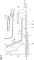
- FIG. 2 an exemplary design for an inventive combustion section 01 is shown.
- the combustion chamber 07 is extending around the rotor axis.
- burners of the burner arrangement 08 are located on the upstream side relative to the combustion chamber 07.
- the combustion casing 11 is built in this exemplary solution by an outer section wall 12, which 12 is arranged on the radial outer side of the combustion chamber 07, and an upstream section wall 13, which 13 is arranged at the upstream side of the combustion chamber 07 and is penetrated by the burners of the burner arrangement 08, and an inner section wall 14, which 14 is arranged on the radial inner side relative to the burner arrangement 08.
- the combustion section further comprises a compressor diffusor 15, which 15 is attached at the downstream side of the compressor section 06 and is located on the side facing the rotor axis relative to the inner section wall 14.
- the diffusor is built in this arrangement by an outer diffusor wall 16 on the radial outer side of the compressor diffusor 15 and an inner diffusor wall 19 on the radial inner side of the compressor diffusor 15.
- a shielding 21 is attached at the inner section wall 14 with a free space in-between.
- the free space 22 is realized by a recess 22.
- the shielding 21 is arranged within the recess 22 as shown in the figure.
- the recess leads to a free distance 24 between the radial inner side of the inner section wall 14 and the radial outer side of the shielding 21 - in respect to the same axial position.
- the arrangement with the inner section wall 14 and the shielding 21 defines a thickness 23 of the arrangement at the location of the shielding 21 from the radial inner side of the shielding 21 to the radial outer side of the inner section wall 14.
- a free distance 24 of about a quarter of the thickness 23 of the arrangement is used.
- the wall end 18 of the outer diffusor wall 16 which is located in axial direction between the upstream end of the shielding 21 and the middle of the shielding 21. As shown in the figure a distance from the wall end 18 to the shielding 21 is about the same as the free distance 24.
- an inner cover 25 arranged on the radial outer side at the inner section wall 14, and an upstream cover 28 arranged on the downstream side at the upstream section wall 13 is used.
- an inner gap 26 and at the upstream cover 28 an upstream gap 29 is applied to protect the combustion casing 11 especially in the corner between the upstream section wall 13 and the inner section wall 14 against rapid thermal expansion due to the start-up of the gas turbine 02.
- a bend 27, 30 is arranged, which are each in contact with the respective section wall 13, 14.
Landscapes
- Engineering & Computer Science (AREA)
- Mechanical Engineering (AREA)
- General Engineering & Computer Science (AREA)
- Chemical & Material Sciences (AREA)
- Combustion & Propulsion (AREA)
- Structures Of Non-Positive Displacement Pumps (AREA)
- Turbine Rotor Nozzle Sealing (AREA)
- Supercharger (AREA)
Priority Applications (5)
| Application Number | Priority Date | Filing Date | Title |
|---|---|---|---|
| EP21153211.4A EP4033073A1 (de) | 2021-01-25 | 2021-01-25 | Brennkammerabschnitt mit einer gehäuseabschirmung |
| PCT/EP2021/078132 WO2022156925A1 (en) | 2021-01-25 | 2021-10-12 | Combustion section with a casing shielding |
| CN202180091775.2A CN116802384B (zh) | 2021-01-25 | 2021-10-12 | 具有外壳屏蔽件的燃烧部段 |
| EP21801015.5A EP4244469B1 (de) | 2021-01-25 | 2021-10-12 | Brennkammerabschnitt mit einer gehäuseabschirmung |
| US18/270,855 US12215864B2 (en) | 2021-01-25 | 2021-10-12 | Combustion section with a casing shielding |
Applications Claiming Priority (1)
| Application Number | Priority Date | Filing Date | Title |
|---|---|---|---|
| EP21153211.4A EP4033073A1 (de) | 2021-01-25 | 2021-01-25 | Brennkammerabschnitt mit einer gehäuseabschirmung |
Publications (1)
| Publication Number | Publication Date |
|---|---|
| EP4033073A1 true EP4033073A1 (de) | 2022-07-27 |
Family
ID=74236040
Family Applications (2)
| Application Number | Title | Priority Date | Filing Date |
|---|---|---|---|
| EP21153211.4A Withdrawn EP4033073A1 (de) | 2021-01-25 | 2021-01-25 | Brennkammerabschnitt mit einer gehäuseabschirmung |
| EP21801015.5A Active EP4244469B1 (de) | 2021-01-25 | 2021-10-12 | Brennkammerabschnitt mit einer gehäuseabschirmung |
Family Applications After (1)
| Application Number | Title | Priority Date | Filing Date |
|---|---|---|---|
| EP21801015.5A Active EP4244469B1 (de) | 2021-01-25 | 2021-10-12 | Brennkammerabschnitt mit einer gehäuseabschirmung |
Country Status (4)
| Country | Link |
|---|---|
| US (1) | US12215864B2 (de) |
| EP (2) | EP4033073A1 (de) |
| CN (1) | CN116802384B (de) |
| WO (1) | WO2022156925A1 (de) |
Citations (4)
| Publication number | Priority date | Publication date | Assignee | Title |
|---|---|---|---|---|
| US4719748A (en) * | 1985-05-14 | 1988-01-19 | General Electric Company | Impingement cooled transition duct |
| US5619855A (en) * | 1995-06-07 | 1997-04-15 | General Electric Company | High inlet mach combustor for gas turbine engine |
| US20100257869A1 (en) * | 2003-08-18 | 2010-10-14 | Christian Cornelius | Diffuser arranged between the compressor and the combustion chamber of a gas turbine |
| EP2784267A2 (de) * | 2013-03-26 | 2014-10-01 | Rolls-Royce plc | Gasturbinenmotor- Kühlungsanordnung |
Family Cites Families (1)
| Publication number | Priority date | Publication date | Assignee | Title |
|---|---|---|---|---|
| EP3141705B1 (de) * | 2015-09-08 | 2018-12-26 | Ansaldo Energia Switzerland AG | Gasturbinenrotorabdeckung |
-
2021
- 2021-01-25 EP EP21153211.4A patent/EP4033073A1/de not_active Withdrawn
- 2021-10-12 CN CN202180091775.2A patent/CN116802384B/zh active Active
- 2021-10-12 WO PCT/EP2021/078132 patent/WO2022156925A1/en not_active Ceased
- 2021-10-12 EP EP21801015.5A patent/EP4244469B1/de active Active
- 2021-10-12 US US18/270,855 patent/US12215864B2/en active Active
Patent Citations (4)
| Publication number | Priority date | Publication date | Assignee | Title |
|---|---|---|---|---|
| US4719748A (en) * | 1985-05-14 | 1988-01-19 | General Electric Company | Impingement cooled transition duct |
| US5619855A (en) * | 1995-06-07 | 1997-04-15 | General Electric Company | High inlet mach combustor for gas turbine engine |
| US20100257869A1 (en) * | 2003-08-18 | 2010-10-14 | Christian Cornelius | Diffuser arranged between the compressor and the combustion chamber of a gas turbine |
| EP2784267A2 (de) * | 2013-03-26 | 2014-10-01 | Rolls-Royce plc | Gasturbinenmotor- Kühlungsanordnung |
Also Published As
| Publication number | Publication date |
|---|---|
| US20240302043A1 (en) | 2024-09-12 |
| EP4244469A1 (de) | 2023-09-20 |
| CN116802384B (zh) | 2026-04-14 |
| EP4244469C0 (de) | 2025-03-12 |
| CN116802384A (zh) | 2023-09-22 |
| EP4244469B1 (de) | 2025-03-12 |
| WO2022156925A1 (en) | 2022-07-28 |
| US12215864B2 (en) | 2025-02-04 |
Similar Documents
| Publication | Publication Date | Title |
|---|---|---|
| US6758653B2 (en) | Ceramic matrix composite component for a gas turbine engine | |
| EP3543500B1 (de) | Turbinengehäuse und damit ausgestatteter turbolader | |
| RU2337248C2 (ru) | Теплозащитная стенка, корпус подшипника, корпус турбины для работающей на отработавших газах турбины и работающая на отработавших газах турбина (варианты) | |
| US20060127244A1 (en) | Turbocharger | |
| US8784076B2 (en) | Disk spring for a turbocharger | |
| JP4526976B2 (ja) | ターボ機械の高圧タービンのリングスペーサセクタを軸方向に保持するための装置 | |
| US8322979B2 (en) | Pane arrangement for a turbocharger | |
| JP6385955B2 (ja) | タービンフレームアセンブリおよびタービンフレームアセンブリを設計する方法 | |
| KR970075266A (ko) | 배출가스 터보과급기의 배출가스 터빈 | |
| EP3112633B1 (de) | Turbinengehäuse aus blechmetall | |
| KR101055231B1 (ko) | 터빈 하우징 | |
| CN100510539C (zh) | 燃气轮机用的燃烧室 | |
| CN109563771B (zh) | 涡轮壳体、排气涡轮、以及增压器 | |
| EP4244469B1 (de) | Brennkammerabschnitt mit einer gehäuseabschirmung | |
| US9540953B2 (en) | Housing-side structure of a turbomachine | |
| US20230340926A1 (en) | Sealing assembly for a turbine ejection cone | |
| US20110255956A1 (en) | Gas turbine having cooling insert | |
| US10054000B2 (en) | Turbine casing made of two materials | |
| EP4010632B1 (de) | Brennkammer für eine gasturbine mit wandkühlung | |
| JP7644306B2 (ja) | 低摩耗タービンハウジングクランプ接続部 | |
| RU2785313C1 (ru) | Камера сгорания с охлаждением стенок | |
| CN117098908A (zh) | 用于涡轮机的涡轮环组件 | |
| JPS62197645A (ja) | ガスタ−ビン燃焼器 | |
| JPH02153231A (ja) | ガスタービン |
Legal Events
| Date | Code | Title | Description |
|---|---|---|---|
| PUAI | Public reference made under article 153(3) epc to a published international application that has entered the european phase |
Free format text: ORIGINAL CODE: 0009012 |
|
| STAA | Information on the status of an ep patent application or granted ep patent |
Free format text: STATUS: THE APPLICATION HAS BEEN PUBLISHED |
|
| AK | Designated contracting states |
Kind code of ref document: A1 Designated state(s): AL AT BE BG CH CY CZ DE DK EE ES FI FR GB GR HR HU IE IS IT LI LT LU LV MC MK MT NL NO PL PT RO RS SE SI SK SM TR |
|
| STAA | Information on the status of an ep patent application or granted ep patent |
Free format text: STATUS: THE APPLICATION IS DEEMED TO BE WITHDRAWN |
|
| 18D | Application deemed to be withdrawn |
Effective date: 20230128 |