EP4033112A1 - Pressmutter - Google Patents
Pressmutter Download PDFInfo
- Publication number
- EP4033112A1 EP4033112A1 EP20866602.4A EP20866602A EP4033112A1 EP 4033112 A1 EP4033112 A1 EP 4033112A1 EP 20866602 A EP20866602 A EP 20866602A EP 4033112 A1 EP4033112 A1 EP 4033112A1
- Authority
- EP
- European Patent Office
- Prior art keywords
- crimp
- nut
- peripheral side
- end surface
- inner peripheral
- Prior art date
- Legal status (The legal status is an assumption and is not a legal conclusion. Google has not performed a legal analysis and makes no representation as to the accuracy of the status listed.)
- Withdrawn
Links
- 230000002093 peripheral effect Effects 0.000 claims abstract description 59
- 230000000452 restraining effect Effects 0.000 abstract description 3
- 239000000463 material Substances 0.000 description 10
- 238000003466 welding Methods 0.000 description 9
- 230000000052 comparative effect Effects 0.000 description 6
- 238000003780 insertion Methods 0.000 description 4
- 230000037431 insertion Effects 0.000 description 4
- XEEYBQQBJWHFJM-UHFFFAOYSA-N Iron Chemical compound [Fe] XEEYBQQBJWHFJM-UHFFFAOYSA-N 0.000 description 2
- 229910000831 Steel Inorganic materials 0.000 description 2
- 230000004323 axial length Effects 0.000 description 2
- 239000007789 gas Substances 0.000 description 2
- 239000010959 steel Substances 0.000 description 2
- 229910000975 Carbon steel Inorganic materials 0.000 description 1
- CWYNVVGOOAEACU-UHFFFAOYSA-N Fe2+ Chemical compound [Fe+2] CWYNVVGOOAEACU-UHFFFAOYSA-N 0.000 description 1
- 239000010962 carbon steel Substances 0.000 description 1
- 230000000694 effects Effects 0.000 description 1
- 239000003517 fume Substances 0.000 description 1
- 229910052742 iron Inorganic materials 0.000 description 1
- 239000002184 metal Substances 0.000 description 1
- 229910052751 metal Inorganic materials 0.000 description 1
- 238000000034 method Methods 0.000 description 1
- 230000000149 penetrating effect Effects 0.000 description 1
- 239000011347 resin Substances 0.000 description 1
- 229920005989 resin Polymers 0.000 description 1
- 238000007665 sagging Methods 0.000 description 1
- 239000010935 stainless steel Substances 0.000 description 1
- 229910001220 stainless steel Inorganic materials 0.000 description 1
Images

Classifications
-
- F—MECHANICAL ENGINEERING; LIGHTING; HEATING; WEAPONS; BLASTING
- F16—ENGINEERING ELEMENTS AND UNITS; GENERAL MEASURES FOR PRODUCING AND MAINTAINING EFFECTIVE FUNCTIONING OF MACHINES OR INSTALLATIONS; THERMAL INSULATION IN GENERAL
- F16B—DEVICES FOR FASTENING OR SECURING CONSTRUCTIONAL ELEMENTS OR MACHINE PARTS TOGETHER, e.g. NAILS, BOLTS, CIRCLIPS, CLAMPS, CLIPS OR WEDGES; JOINTS OR JOINTING
- F16B37/00—Nuts or like thread-engaging members
- F16B37/04—Devices for fastening nuts to surfaces, e.g. sheets, plates
- F16B37/06—Devices for fastening nuts to surfaces, e.g. sheets, plates by means of welding or riveting
- F16B37/062—Devices for fastening nuts to surfaces, e.g. sheets, plates by means of welding or riveting by means of riveting
- F16B37/065—Devices for fastening nuts to surfaces, e.g. sheets, plates by means of welding or riveting by means of riveting by deforming the material of the nut
-
- B—PERFORMING OPERATIONS; TRANSPORTING
- B21—MECHANICAL METAL-WORKING WITHOUT ESSENTIALLY REMOVING MATERIAL; PUNCHING METAL
- B21D—WORKING OR PROCESSING OF SHEET METAL OR METAL TUBES, RODS OR PROFILES WITHOUT ESSENTIALLY REMOVING MATERIAL; PUNCHING METAL
- B21D39/00—Application of procedures in order to connect objects or parts, e.g. coating with sheet metal otherwise than by plating; Tube expanders
- B21D39/06—Application of procedures in order to connect objects or parts, e.g. coating with sheet metal otherwise than by plating; Tube expanders of tubes in openings, e.g. rolling-in
-
- B—PERFORMING OPERATIONS; TRANSPORTING
- B23—MACHINE TOOLS; METAL-WORKING NOT OTHERWISE PROVIDED FOR
- B23P—METAL-WORKING NOT OTHERWISE PROVIDED FOR; COMBINED OPERATIONS; UNIVERSAL MACHINE TOOLS
- B23P19/00—Machines for simply fitting together or separating metal parts or objects, or metal and non-metal parts, whether or not involving some deformation; Tools or devices therefor so far as not provided for in other classes
- B23P19/04—Machines for simply fitting together or separating metal parts or objects, or metal and non-metal parts, whether or not involving some deformation; Tools or devices therefor so far as not provided for in other classes for assembling or disassembling parts
- B23P19/06—Screw or nut setting or loosening machines
- B23P19/062—Pierce nut setting machines
-
- B—PERFORMING OPERATIONS; TRANSPORTING
- B21—MECHANICAL METAL-WORKING WITHOUT ESSENTIALLY REMOVING MATERIAL; PUNCHING METAL
- B21D—WORKING OR PROCESSING OF SHEET METAL OR METAL TUBES, RODS OR PROFILES WITHOUT ESSENTIALLY REMOVING MATERIAL; PUNCHING METAL
- B21D53/00—Making other particular articles
- B21D53/88—Making other particular articles other parts for vehicles, e.g. cowlings, mudguards
Definitions
- the present disclosure relates to a crimp nut to be attached to a plate to be attached.
- the nut When a nut is attached to a plate formed by a middle or large thickness plate, the nut is generally attached by welding.
- a press-fit nut described in Patent Literature 2 has a nut fixing portion to be inserted into an attachment hole of the panel.
- the nut fixing portion has a step portion, a groove portion, and an insertion portion in this order from the top. Screws are formed on the side surfaces of the step portion and the insertion portion. When the insertion portion is inserted into the attachment hole, the insertion portion deforms the side surface portion of the attachment hole, and the deformed material is inserted between the screws.
- the step portion allows the material of the side surface of the attachment hole to enter the groove portion.
- the crimp nut described in Patent Literature 1 and the press-fit nut described in Patent Literature 2 can solve the above-mentioned problems associated with welding since they do not use welding.
- the crimp nut described in Patent Literature 1 has a drawback that the base portion of the crimp portion is easily damaged when a high torque is applied to the nut after attached.
- the press-fit nut described in Patent Literature 2 is attached simply by press-fit. Therefore, the press-fit nut described in Patent Literature 2 has a drawback that the nut after attached is easily loosened when a high torque is applied.
- a crimp nut to be attached to a pilot hole of a plate to be attached comprising: a nut portion having a screw hole; and a crimp portion extending axially from an end surface of the nut portion so as to be crimped to an inner peripheral surface of the pilot hole,
- a position of the outer peripheral side end surface in an axial direction is arranged at a tip end side of the crimp portion than the inner peripheral side end surface, or at the same position as the inner peripheral side end surface.
- a crimp nut capable of preventing or restraining deformation of a screw hole of a nut portion.
- FIG. 1 is a side view of the crimp nut according to the present invention. Alternate long and short dash line in the figure is a central axis C, and the left side of the central axis C shows a cross section of the crimp nut.
- FIG. 2 is a view taken along the line A-A in FIG. 1 when the crimp nut is viewed from a crimp portion side.
- a crimp nut 1 includes a nut portion 2 and a crimp portion 5.
- the crimp portion 5 is formed to extend axially from one end surface 2a in the axial direction of the nut portion 2 and is inserted into a pilot or preparatory hole 4 of a plate to be the attached 3.
- the nut portion 2 is formed in substantially the same shape as the hexagon nut. Specifically, the nut portion 2 includes a nut main body portion 6 formed in a hexagonal cylinder shape, and a screw hole 7 formed coaxially with the nut main body portion 6. A female screw 7a is formed on an inner peripheral surface of the screw hole 7. Further, on the crimp portion 5 side of the nut portion 2, an outer peripheral side end surface 8 located on the outer peripheral side of the crimp portion 5 is formed, and an inner peripheral side end surface 9 located on the inner peripheral side of the crimp portion 5 is formed. The outer peripheral side end surface 8 constitutes a seating surface to be seated on an attaching surface 3a of the plate to be attached 3.
- the crimp portion 5 is formed in a cylindrical shape, and extends from the outer peripheral side end surface 8 and the inner peripheral side end surface 9 of the nut portion 2 in the axial direction of the central axis C. Further, the crimp portion 5 is formed in a tapered shape whose outer circumference is reduced in diameter toward a tip end.
- An inclination angle ⁇ of the outer peripheral surface with respect to the axial direction of the central axis C may be within a range of approximately 1° or more and 7° or less. It should be noted that each of the above numerical values is merely an example and can be changed as appropriate.
- the tip end of the crimp portion 5 is formed to have a diameter smaller than a diameter ⁇ of the narrowest portion of the pilot hole 4.
- An inner diameter d of the crimp portion 5 is formed to be constant over the entire length, and is formed to be larger than a valley diameter D1 of the female screw 7a. Further, an axial length a of the crimp portion 5 is formed longer than an axial length b of the pilot hole 4.
- an outer rounded portion 10 having an arcuate cross section is formed to connect an outer peripheral surface 5a of the crimp portion 5 and the outer peripheral side end surface 8. Further, on the base end portion of the crimp portion 5, an inner rounded portion 11 having an arcuate cross section is formed to connect an inner peripheral surface 5b of the crimp portion 5 and the inner peripheral side end surface 9.
- the nut portion 2 and the crimp portion 5 are made of rolled steel for general structure.
- the nut portion 2 and the crimp portion 5 may be formed of other materials generally used for hexagon nut, and may be formed of, for example, a carbon steel material for machine structure, a stainless steel material, or the like.
- the plate to be attached 3 is made of a flat steel material.
- the plate to be attached 3 may be any other plate as long as it has an attaching surface on which the outer peripheral side end surface 8 of the crimp nut 1 is seated.
- the plate 3 may be made of a channel material used for a chassis frame of a vehicle or the like.
- material of the plate to be attached 3 is not limited to iron, and may be a resin or a non-ferrous metal.
- the radius R1 of the outer rounded portion 10 is set to be larger than the radius R2 of the inner rounded portion 11. Specifically, if the radius R2 of the inner rounded portion 11 is in the range of 0.1 mm or more and 0.5 mm or less, the radius R1 of the outer rounded portion 10 is set to be larger than the radius R2 by 0.3 mm to 1.0 mm.
- a pilot hole 4 (pierced hole) is formed in the plate 3 by press working.
- a surface side (shear surface 23 side) facing the punch for press working (not shown)
- sagging a phenomenon in which the hole edge is dented over the entire circumference
- hole diameter is enlarged on a surface side (fracture surface 24 side) from which the punch comes out after penetrating the plate 3.
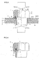
- the crimp portion 5 of the crimp nut 1 is inserted into the pilot hole 4 of the plate 3 from the shear surface 23 side.
- the crimp portion 5 may be inserted from the fracture surface 24 side of the pilot hole 4.
- a pin (not shown) is inserted into the crimp portion 5.
- the pin is used for preventing the crimp portion 5 from being deformed inward in the radial direction.
- the pin is tightly fitted in the crimp portion 5.
- the crimp nut 1 is sandwiched from both sides in the axial direction and pressed in the axial direction.
- the crimp force applied to the crimp portion 5 may be transmitted to the screw hole 7 inward in the radial direction of the nut portion 2, and the screw hole 7 may be deformed so as to protrude inward in the radial direction.
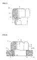
- the crimp nut 1 according to the present embodiment can transmit the crimp force outward in the radial direction of the nut portion 2. Therefore, the crimp nut 1 according to the present embodiment can prevent or restrain the deformation of the screw hole 7 more than the crimp nut 30 of the comparative example shown in FIG. 4 .
- deflecting the crimp force away from the screw hole 7 of the nut portion 2 and deflecting it radially outward results in directing the crimp force in the axial direction to the inner peripheral surface 25 of the hole 4 of the plate 3. Therefore, adhesion between the inner peripheral surface 25 of the pilot hole 4 and the crimp portion 5 can be enhanced.
- the outer peripheral side end surface 8 of the crimp nut 1 according to the present embodiment is arranged at a tip side of the crimp portion 5 than the inner peripheral side end surface 9.
- material of the crimp portion 5 that has been compressed and deformed at the time of crimp can easily be transmitted outward in the radial direction along the outer rounded portion 10. Therefore, the screw deformation and the screw pitch collapse of the nut portion 2 are more effectively prevented or restrained.
- the crimp nut 1 can transmit the crimp force outward in the radial direction of the nut portion 2.
- the crimp nut 1 according to the present embodiment can prevent or restrain the deformation of the screw hole 7 as compared with the crimp nut 40 of the comparative example shown in FIG. 5 , and can prevent or restrain the occurrence of the screw deformation and the screw pitch collapse.
- the crimp portion 5 is crushed in the axial direction and enlarged in diameter so as to be firmly crimped to the inner peripheral surface 25 of the pilot hole 4. Furthermore, diameter of the pilot hole 4 is larger on the fracture surface 24 side than on the shear surface 23 side. Therefore, the crimp portion 5 on the fracture surface 24 side has a larger diameter than the crimp portion 5 on the shear surface 23 side, suitably functions as a stopper for the crimp nut 1, and firmly fixes the crimp nut 1 to the plate 3 by sandwiching a part of the plate 3 with the outer peripheral side end surface 8.
Landscapes
- Engineering & Computer Science (AREA)
- Mechanical Engineering (AREA)
- General Engineering & Computer Science (AREA)
- Connection Of Plates (AREA)
- Forging (AREA)
Applications Claiming Priority (2)
| Application Number | Priority Date | Filing Date | Title |
|---|---|---|---|
| JP2019170686A JP6824352B1 (ja) | 2019-09-19 | 2019-09-19 | カシメナット |
| PCT/JP2020/033985 WO2021054205A1 (ja) | 2019-09-19 | 2020-09-08 | カシメナット |
Publications (2)
| Publication Number | Publication Date |
|---|---|
| EP4033112A1 true EP4033112A1 (de) | 2022-07-27 |
| EP4033112A4 EP4033112A4 (de) | 2023-10-11 |
Family
ID=74228068
Family Applications (1)
| Application Number | Title | Priority Date | Filing Date |
|---|---|---|---|
| EP20866602.4A Withdrawn EP4033112A4 (de) | 2019-09-19 | 2020-09-08 | Pressmutter |
Country Status (3)
| Country | Link |
|---|---|
| EP (1) | EP4033112A4 (de) |
| JP (1) | JP6824352B1 (de) |
| WO (1) | WO2021054205A1 (de) |
Families Citing this family (1)
| Publication number | Priority date | Publication date | Assignee | Title |
|---|---|---|---|---|
| CN114135642B (zh) * | 2021-12-11 | 2025-11-28 | 上海鸣志派博思自动化技术有限公司 | 一种可持续消间隙螺母 |
Family Cites Families (7)
| Publication number | Priority date | Publication date | Assignee | Title |
|---|---|---|---|---|
| DE844232C (de) * | 1944-07-11 | 1952-07-17 | Daimler Benz Ag | Einnietmutter |
| US5237733A (en) * | 1980-02-02 | 1993-08-24 | Multifastener Corporation | Female die assembly for attaching a self-attaching fastening element and method of attachment |
| US7032296B2 (en) * | 2003-11-21 | 2006-04-25 | Newfrey Llc | Self-piercing fastening system |
| JP2013113396A (ja) | 2011-11-30 | 2013-06-10 | Nippon Pop Rivets & Fasteners Ltd | 圧入ナット |
| DE102013217640A1 (de) * | 2013-09-04 | 2015-03-05 | Profil Verbindungstechnik Gmbh & Co. Kg | Verfahren zur Anbringung eines Befestigungselements an ein Werkstück, Kombination einer Scheibe mit einer Matrize sowie Matrize |
| CN105201994A (zh) * | 2015-10-16 | 2015-12-30 | 贵州航天精工制造有限公司 | 一种多功能自锁螺母及其制作方法 |
| JP6891081B2 (ja) * | 2017-09-20 | 2021-06-18 | プレス工業株式会社 | カシメナット、カシメナット用カシメ工具及びカシメナットの取付方法 |
-
2019
- 2019-09-19 JP JP2019170686A patent/JP6824352B1/ja active Active
-
2020
- 2020-09-08 WO PCT/JP2020/033985 patent/WO2021054205A1/ja not_active Ceased
- 2020-09-08 EP EP20866602.4A patent/EP4033112A4/de not_active Withdrawn
Also Published As
| Publication number | Publication date |
|---|---|
| JP2021046921A (ja) | 2021-03-25 |
| JP6824352B1 (ja) | 2021-02-03 |
| EP4033112A4 (de) | 2023-10-11 |
| WO2021054205A1 (ja) | 2021-03-25 |
Similar Documents
| Publication | Publication Date | Title |
|---|---|---|
| US8506228B2 (en) | Punch rivet and die | |
| CN1332134C (zh) | 用于模锻套环的具有拉槽的拉杆紧固件 | |
| US11028868B2 (en) | Press-fit connection between a high-strength component and a press-fit element, method for making such a press-fit connection, and press-fit element for such a press-fit connection | |
| US8931990B2 (en) | Pierce nut and use thereof | |
| EP2402620A1 (de) | Vernieteter Bolzen | |
| EP3263921A1 (de) | Blindnietmutter, befestigungsanordnung mit einer blindnietmutter und befestigungsverfahren | |
| EP2580485B1 (de) | Blindniet und befestigungsanordnung mit einem blindniet | |
| CN105221537A (zh) | 压接在支撑件上的部件,包括该部件的装置及其制造方法 | |
| US6527490B1 (en) | Punching, stamping rivet | |
| EP2787221A1 (de) | Stanzmutter für ein hochfestes stahlblech | |
| US20210262509A1 (en) | Deformable sleeve nut and a method of manufacturing | |
| ZA200404725B (en) | Method of fastening | |
| US6905296B2 (en) | Peel-type blind rivet | |
| EP4033112A1 (de) | Pressmutter | |
| EP4032632A1 (de) | Verfahren zum befestigen einer stauchmutter und stauchwerkzeug | |
| JP2020029876A (ja) | バーリング締結方法、バーリング締結構造およびバーリングパンチ | |
| US20200108475A1 (en) | Press-in connecting element and method for anchoring press-in connecting elements in a permanently deformable flat metal material or components or workpieces produced therefrom | |
| US3645125A (en) | Lockbolt swaging apparatus | |
| JP6891081B2 (ja) | カシメナット、カシメナット用カシメ工具及びカシメナットの取付方法 | |
| EP3610965A1 (de) | Verfahren zur herstellung eines schweissbolzens | |
| EP2852767B1 (de) | Bund mit pressanzeige | |
| US8230574B2 (en) | Method for inserting connecting elements in metal sheets and connection between a metal sheet and a connecting element | |
| US11745250B2 (en) | Swaging device and swaging method | |
| EP1055075A1 (de) | Blindnietartiges verbindungselement | |
| US8584343B2 (en) | Method for the application of a joint or function element to planar material rivet connection |
Legal Events
| Date | Code | Title | Description |
|---|---|---|---|
| STAA | Information on the status of an ep patent application or granted ep patent |
Free format text: STATUS: THE INTERNATIONAL PUBLICATION HAS BEEN MADE |
|
| PUAI | Public reference made under article 153(3) epc to a published international application that has entered the european phase |
Free format text: ORIGINAL CODE: 0009012 |
|
| STAA | Information on the status of an ep patent application or granted ep patent |
Free format text: STATUS: REQUEST FOR EXAMINATION WAS MADE |
|
| 17P | Request for examination filed |
Effective date: 20220217 |
|
| AK | Designated contracting states |
Kind code of ref document: A1 Designated state(s): AL AT BE BG CH CY CZ DE DK EE ES FI FR GB GR HR HU IE IS IT LI LT LU LV MC MK MT NL NO PL PT RO RS SE SI SK SM TR |
|
| DAV | Request for validation of the european patent (deleted) | ||
| DAX | Request for extension of the european patent (deleted) | ||
| REG | Reference to a national code |
Ref country code: DE Ref legal event code: R079 Free format text: PREVIOUS MAIN CLASS: F16B0037040000 Ipc: F16B0037060000 |
|
| A4 | Supplementary search report drawn up and despatched |
Effective date: 20230907 |
|
| RIC1 | Information provided on ipc code assigned before grant |
Ipc: B23P 19/06 20060101ALI20230901BHEP Ipc: B21D 39/00 20060101ALI20230901BHEP Ipc: F16B 37/06 20060101AFI20230901BHEP |
|
| STAA | Information on the status of an ep patent application or granted ep patent |
Free format text: STATUS: THE APPLICATION HAS BEEN WITHDRAWN |
|
| 18W | Application withdrawn |
Effective date: 20240208 |