EP4033156A1 - Gargerät mit halteplatte für eine gargeräteleuchte - Google Patents
Gargerät mit halteplatte für eine gargeräteleuchte Download PDFInfo
- Publication number
- EP4033156A1 EP4033156A1 EP21204688.2A EP21204688A EP4033156A1 EP 4033156 A1 EP4033156 A1 EP 4033156A1 EP 21204688 A EP21204688 A EP 21204688A EP 4033156 A1 EP4033156 A1 EP 4033156A1
- Authority
- EP
- European Patent Office
- Prior art keywords
- cooking appliance
- cooking
- light
- opening
- holding plate
- Prior art date
- Legal status (The legal status is an assumption and is not a legal conclusion. Google has not performed a legal analysis and makes no representation as to the accuracy of the status listed.)
- Granted
Links
Images


Classifications
-
- F—MECHANICAL ENGINEERING; LIGHTING; HEATING; WEAPONS; BLASTING
- F21—LIGHTING
- F21S—NON-PORTABLE LIGHTING DEVICES; SYSTEMS THEREOF; VEHICLE LIGHTING DEVICES SPECIALLY ADAPTED FOR VEHICLE EXTERIORS
- F21S8/00—Lighting devices intended for fixed installation
-
- A—HUMAN NECESSITIES
- A21—BAKING; EDIBLE DOUGHS
- A21B—BAKERS' OVENS; MACHINES OR EQUIPMENT FOR BAKING
- A21B3/00—Parts or accessories of ovens
- A21B3/10—Means for illuminating ovens
-
- F—MECHANICAL ENGINEERING; LIGHTING; HEATING; WEAPONS; BLASTING
- F21—LIGHTING
- F21V—FUNCTIONAL FEATURES OR DETAILS OF LIGHTING DEVICES OR SYSTEMS THEREOF; STRUCTURAL COMBINATIONS OF LIGHTING DEVICES WITH OTHER ARTICLES, NOT OTHERWISE PROVIDED FOR
- F21V17/00—Fastening of component parts of lighting devices, e.g. shades, globes, refractors, reflectors, filters, screens, grids or protective cages
-
- F—MECHANICAL ENGINEERING; LIGHTING; HEATING; WEAPONS; BLASTING
- F21—LIGHTING
- F21V—FUNCTIONAL FEATURES OR DETAILS OF LIGHTING DEVICES OR SYSTEMS THEREOF; STRUCTURAL COMBINATIONS OF LIGHTING DEVICES WITH OTHER ARTICLES, NOT OTHERWISE PROVIDED FOR
- F21V17/00—Fastening of component parts of lighting devices, e.g. shades, globes, refractors, reflectors, filters, screens, grids or protective cages
- F21V17/10—Fastening of component parts of lighting devices, e.g. shades, globes, refractors, reflectors, filters, screens, grids or protective cages characterised by specific fastening means or way of fastening
- F21V17/14—Bayonet-type fastening
-
- F—MECHANICAL ENGINEERING; LIGHTING; HEATING; WEAPONS; BLASTING
- F21—LIGHTING
- F21V—FUNCTIONAL FEATURES OR DETAILS OF LIGHTING DEVICES OR SYSTEMS THEREOF; STRUCTURAL COMBINATIONS OF LIGHTING DEVICES WITH OTHER ARTICLES, NOT OTHERWISE PROVIDED FOR
- F21V17/00—Fastening of component parts of lighting devices, e.g. shades, globes, refractors, reflectors, filters, screens, grids or protective cages
- F21V17/10—Fastening of component parts of lighting devices, e.g. shades, globes, refractors, reflectors, filters, screens, grids or protective cages characterised by specific fastening means or way of fastening
- F21V17/16—Fastening of component parts of lighting devices, e.g. shades, globes, refractors, reflectors, filters, screens, grids or protective cages characterised by specific fastening means or way of fastening by deformation of parts; Snap action mounting
-
- F—MECHANICAL ENGINEERING; LIGHTING; HEATING; WEAPONS; BLASTING
- F21—LIGHTING
- F21V—FUNCTIONAL FEATURES OR DETAILS OF LIGHTING DEVICES OR SYSTEMS THEREOF; STRUCTURAL COMBINATIONS OF LIGHTING DEVICES WITH OTHER ARTICLES, NOT OTHERWISE PROVIDED FOR
- F21V19/00—Fastening of light sources or lamp holders
- F21V19/001—Fastening of light sources or lamp holders the light sources being semiconductors devices, e.g. LEDs
- F21V19/0015—Fastening arrangements intended to retain light sources
-
- F—MECHANICAL ENGINEERING; LIGHTING; HEATING; WEAPONS; BLASTING
- F21—LIGHTING
- F21V—FUNCTIONAL FEATURES OR DETAILS OF LIGHTING DEVICES OR SYSTEMS THEREOF; STRUCTURAL COMBINATIONS OF LIGHTING DEVICES WITH OTHER ARTICLES, NOT OTHERWISE PROVIDED FOR
- F21V3/00—Globes; Bowls; Cover glasses
-
- F—MECHANICAL ENGINEERING; LIGHTING; HEATING; WEAPONS; BLASTING
- F21—LIGHTING
- F21V—FUNCTIONAL FEATURES OR DETAILS OF LIGHTING DEVICES OR SYSTEMS THEREOF; STRUCTURAL COMBINATIONS OF LIGHTING DEVICES WITH OTHER ARTICLES, NOT OTHERWISE PROVIDED FOR
- F21V31/00—Gas-tight or water-tight arrangements
- F21V31/005—Sealing arrangements therefor
-
- F—MECHANICAL ENGINEERING; LIGHTING; HEATING; WEAPONS; BLASTING
- F21—LIGHTING
- F21V—FUNCTIONAL FEATURES OR DETAILS OF LIGHTING DEVICES OR SYSTEMS THEREOF; STRUCTURAL COMBINATIONS OF LIGHTING DEVICES WITH OTHER ARTICLES, NOT OTHERWISE PROVIDED FOR
- F21V33/00—Structural combinations of lighting devices with other articles, not otherwise provided for
-
- F—MECHANICAL ENGINEERING; LIGHTING; HEATING; WEAPONS; BLASTING
- F24—HEATING; RANGES; VENTILATING
- F24C—DOMESTIC STOVES OR RANGES ; DETAILS OF DOMESTIC STOVES OR RANGES, OF GENERAL APPLICATION
- F24C15/00—Details
- F24C15/008—Illumination for oven cavities
-
- G—PHYSICS
- G02—OPTICS
- G02B—OPTICAL ELEMENTS, SYSTEMS OR APPARATUS
- G02B6/00—Light guides; Structural details of arrangements comprising light guides and other optical elements, e.g. couplings
- G02B6/0001—Light guides; Structural details of arrangements comprising light guides and other optical elements, e.g. couplings specially adapted for lighting devices or systems
- G02B6/0005—Light guides; Structural details of arrangements comprising light guides and other optical elements, e.g. couplings specially adapted for lighting devices or systems the light guides being of the fibre type
-
- H—ELECTRICITY
- H05—ELECTRIC TECHNIQUES NOT OTHERWISE PROVIDED FOR
- H05B—ELECTRIC HEATING; ELECTRIC LIGHT SOURCES NOT OTHERWISE PROVIDED FOR; CIRCUIT ARRANGEMENTS FOR ELECTRIC LIGHT SOURCES, IN GENERAL
- H05B6/00—Heating by electric, magnetic or electromagnetic fields
- H05B6/64—Heating using microwaves
- H05B6/6444—Aspects relating to lighting devices in the microwave cavity
-
- F—MECHANICAL ENGINEERING; LIGHTING; HEATING; WEAPONS; BLASTING
- F21—LIGHTING
- F21W—INDEXING SCHEME ASSOCIATED WITH SUBCLASSES F21K, F21L, F21S and F21V, RELATING TO USES OR APPLICATIONS OF LIGHTING DEVICES OR SYSTEMS
- F21W2131/00—Use or application of lighting devices or systems not provided for in codes F21W2102/00-F21W2121/00
- F21W2131/30—Lighting for domestic or personal use
- F21W2131/307—Lighting for domestic or personal use for ovens
-
- F—MECHANICAL ENGINEERING; LIGHTING; HEATING; WEAPONS; BLASTING
- F21—LIGHTING
- F21Y—INDEXING SCHEME ASSOCIATED WITH SUBCLASSES F21K, F21L, F21S and F21V, RELATING TO THE FORM OR THE KIND OF THE LIGHT SOURCES OR OF THE COLOUR OF THE LIGHT EMITTED
- F21Y2115/00—Light-generating elements of semiconductor light sources
- F21Y2115/10—Light-emitting diodes [LED]
Definitions
- Cooking devices are well known from the prior art in the form of ovens, steam cookers, microwaves or other devices for private households or commercial purposes. They are used to prepare food and for this purpose have a cooking chamber which is formed by the so-called muffle and its walls, ie the muffle walls or cooking chamber walls.
- cooking appliances have lighting such as that found in the applicant's own DE 50 2006 001 187 is described. Such lights sit in openings in the cooking chamber wall, which are introduced into the cooking chamber wall during manufacture of the muffle.
- the muffle is usually a multi-part component made of metal.
- the muffle parts are formed from sheet metal in presses.
- the tools and equipment for producing the muffle parts are very expensive, so that manufacturers of cooking appliances strive to utilize the tools sufficiently and produce different appliance types and appliance models using the same muffle.
- the object of the invention is therefore to equip a cooking appliance with an opening in the wall of the cooking appliance designed for the use of conventional lights with a cooking appliance light based on LED technology.
- the opening in the cooking chamber wall has a first opening size
- the receiving opening of the holding plate has a second opening size, which is reduced compared to the first opening size
- the openings in the cooking chamber wall often have grooves.
- these are generally used to hold the lamp socket in a twist-proof manner in order to be able to rotate a glass cover relative to a socket housing and then remove it if the light source needs to be replaced.
- the invention proposes to use this groove as a positioning and so a defined orientation of to secure the retaining plate.
- the holding plate forms a positioning lug which engages in the positioning groove.
- the holding plate in particular the positioning lug of the holding plate, has at least one latching lug which engages behind the cooking chamber wall, in particular if the holding plate has at least one holding foot which engages behind the cooking chamber wall.
- the holding plate is a stamped/bent part in which the holding foot and the positioning lug are notched out of the material of the holding plate.
- the cooking appliance light has a mounting base, by means of which the cooking appliance light is anchored in the holding plate.
- an elastic element is provided is arranged between the mounting base and the retaining plate, which has a sealing effect.
- the holding plate has a sealing element with a receptacle for the light-conducting rod of the cooking appliance light.
- This sealing element prevents vapors from escaping from the cooking chamber, but also serves to hold the cooking chamber light.
- the holding plate is ring-shaped and has two holding feet and a positioning lug, with the holding feet and the positioning lug each being circumferentially offset by approximately 120 degrees.
- the arrangement of a cooking appliance light in a cooking chamber wall section is denoted overall by the reference numeral 10 and in FIGS Figures 1 to 5 in a first embodiment and the Figures 6 to 10 shown in a second embodiment.
- the figures 11 to 13 show further components of the first and second embodiment of the invention. Shown are only essential components for the arrangement. A complete depiction of the cooking appliance and the cooking appliance light has been dispensed with.
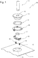
- figure 1 shows first the arrangement 10 with a partial section of a cooking chamber wall 11 of a cooking chamber of a cooking appliance not shown in detail.
- the cooking chamber wall 11 has an opening 12 which is essentially circular and forms a positioning groove 13 .
- a mounting base 15 has a bore 16, which passes through the mounting base 15 and accommodates the fiber optic rod 14 serves.
- the mounting base 15 carries a graphite ring 17, by means of which a seal with respect to the light-weight rod 14 is realized and which is held on the mounting base 15 with a fastening clip 18.
- the fastening clasp 18 in turn is fixed to the fastening base 15 by retaining pins 19 .
- a holding plate 20 receives the fastening base 15 with the interposition of a sealing elastic element 21 in order to hold it in the opening 12 of the cooking chamber wall 11 .
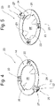
- the holding plate 20 is shown in a perspective view from above figure 4 and perspective view from below in figure 5 shown.
- the holding plate 20 is ring-shaped. Its diameter exceeds the diameter of the opening 12 in the cooking chamber wall 11 in order to be able to cover it.
- the holding plate 20 is provided with a positioning lug 22 and forms two holding feet 23, which in the embodiment according to Figures 4 and 5 from the annular wall 24 of the retaining plate 20 in the same direction - there to the underside of the retaining plate 20 - are notched.
- the positioning lug 22 is approximately V-shaped, with a root leg 25 connected to the holding plate 20 extending downwards relative to the holding plate 20 and at its lowest point merging into a positioning leg 26 via a connecting arc.
- the positioning leg 26 itself is directed in the direction of the upper side of the holding plate 20, with its free end extending at least as far as the plane of the annular wall 24 of the holding plate 20, but this can also penetrate upwards.
- the positioning leg 26 also carries a radially outwardly notched detent 27, which is used for attachment by reaching under the cooking chamber wall 11.
- the annular wall 24 of the retaining plate 20 forms an annular space 28 in which the mounting base 15 is received.
- the annular space 28 is accordingly the receiving opening of the holding plate 20.
- the annular space 28 transitions into an alignment contour 29 at two diametrically opposite sections. This is congruent in shape with the alignment means 30 of the mounting base 15, which are still to be described, and thus allow the same to be arranged in a defined position in the holding plate 20.
- FIG 11 shows the fastening clasp 18 again in an individual representation.
- the fastening clip 18 initially has a base bar 31 which has a central through-opening 32 for the light-conducting rod 14 and a retaining pin opening 33 on the right and left of the through-opening 32 .
- the base bar 31 is initially used to hold the graphite ring 17 in an in figure 3 and 12 illustrated holding chamber 43 of the mounting base 15 to fix.
- a locking leg 34 which - starting from their on Base bar 31 located origin - are issued funnel-shaped.
- Each latching leg 34 is reshaped in the opposite direction to the deployment direction at its free end.
- These formed ends each form a centering and locking section 35.
- a restoring elastic fixing foot 36 is projected outwards from each locking leg 34, the free end of which is approximately level with the forming line of the respective fixing foot 36 lies.
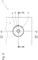
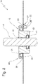
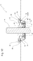
- FIGs 3 and 12 show the arrangement 10 according to FIG figure 1 in assembled condition according to section lines III-III or XII-II in figure 2 . Both figures first show the bore 16 of the mounting base 15 that accommodates the light rod 14 and the holding chamber 43 formed by the mounting base 15 for the graphite ring 17, which seals the bore 16 from the light-conducting rod 14 and thus prevents cooking vapors from escaping through the bore 16.
- the mounting base 15 forms a sealing collar 44 which forms a sealing groove 45 which is open in the direction of the retaining plate 20 and in which the sealing elastic element 21 is arranged and prevents vapors from escaping through the annular space 28 past the mounting base 15 .
- figure 3 also shows how the retaining plate 20 is seated in the opening 12 in the cooking chamber wall 11, with the positioning lug 22 resting in the positioning groove 13.
- the free end of the positioning leg 26 lies in the plane of the cooking chamber wall, the latching lug 27 reaches under the cooking chamber wall 11 and thus secures the holding plate 20 together with the holding feet (not visible) on the cooking chamber wall 11.
- the fastening clip 18 is by means of the retaining pins 19, which pierce the retaining pin openings 33 and engage in blind holes 46 of the mounting base 15, are secured on the mounting base 15 and initially hold the graphite ring 17 in the holding chamber 43.
- the funnel-shaped latching legs 34 pointing away from the bore 16 of the mounting base 15 sit in the alignment contours 29 of the retaining plate 20, with the retaining plate 20 being held between the centering and latching section 35 of each latching leg 34 and the sealing collar 44 of the mounting base 15.
- the latching legs 34 thus serve as alignment means 30 of the mounting base 15.
- each fixing foot 36 serves as a pull-out safeguard holding the retaining plate 20 on the mounting base 15 and, provided that it is displayed accordingly, can also reach behind the cooking chamber wall 11 and thus hold it on the cooking chamber wall 11 in addition to the retaining feet 23 and the locking lug 27 of the positioning leg 26.
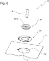
- FIG. 6 shows another embodiment of the invention.
- the arrangement 10 of cooking appliance light shown is only the fiber optic rod 14
- cooking chamber wall 11 - also only a breakout - shown with its essential components.
- the cooking chamber wall 11 as well as the holding plate 20 are designed essentially in accordance with the first embodiment, so that the statements made there also apply to the second embodiment.
- an opening 12 can also be found in the cooking chamber wall 11 in the second embodiment, which forms a positioning groove 13 .
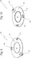
- the in the Figures 9 and 10 The holding plate 20 shown in perspective from above and perspective from below also has a positioning lug 22, which is designed according to the first embodiment and corresponding retaining feet 23 above the first embodiment an alignment contour 29 omitted.
- Another noticeable deviation from the first exemplary embodiment is an annular collar 37 formed by the annular wall 24 and protruding in relation to the underside of the holding plate 20.
- the second embodiment of the invention comprises according to figure 6 in addition, a sealing element 38 with a central hole 39, which serves as a receptacle 40 for the fiber-optic rod 14.
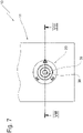
- FIG 8 a sectional view according to section line VIII-VIII in figure 7 , now shows the arrangement according to the second embodiment figure 6 in composite form.
- the sealing element 38 sits in the annular space 28 of the holding plate 20 .
- An annular groove 41 formed by the sealing element 38 and extending around the outer circumference accommodates the edge of the annular wall 24 that delimits the annular space 28 , with the annular collar 37 being accommodated in the annular groove 41 .
- the retaining plate 20 accommodating the sealing element 38 is inserted in the opening 12 of the cooking chamber wall 11, the retaining feet 23 reaching behind the cooking chamber wall 11 and thus receiving the cooking chamber wall 11 between them and the annular wall 24 resting on the cooking chamber wall 11.
- the positioning lug 22 of the holding plate 20 sits in the positioning groove 13 of the opening 12, with the free end of the positioning leg 26 sitting in the plane of the cooking chamber wall 11, whereas the latching lug 27 engages behind the cooking chamber wall 11 and thus anchors the holding plate 20 in the opening 12 .
- the fiber optic rod 14 of the cooking appliance light sits in the receptacle 40 of the sealing element 38 and thus holds the cooking appliance light on the cooking chamber wall 11, which does not rule out other possible fastening elements, particularly in the area of the light facing away from the free end of the light rod.
- Both embodiments show how a cooking chamber wall 11 can be provided with an opening 12 for anchoring conventional cooking chamber lights with, for example, halogen or incandescent filament lamps by using an adapting holding plate 20 with a cooking appliance light based on modern LED technology.
- cooking appliance lights with a fiber optic rod 14 only require small openings 12 in the cooking chamber wall to feed the light into the cooking chamber.
- the holding plate 20 reduces the diameter of the opening 12, optionally with the additional use of a mounting base 15 or a sealing element 38 to a level suitable for the introduction of a fiber optic rod 14.
- the holding plate 20 can be used to fix the cooking appliance light in the cooking appliance, in particular when the holding plate 20 accommodates a fastening base 15 .
- the holding plate 20 is consequently an adapter plate. Thanks to this, it is possible to continue using existing molds and tools and still use LED lights without the latter having to be adapted to existing conditions in terms of their design and shape.
Landscapes
- Engineering & Computer Science (AREA)
- General Engineering & Computer Science (AREA)
- Physics & Mathematics (AREA)
- Mechanical Engineering (AREA)
- Chemical & Material Sciences (AREA)
- Combustion & Propulsion (AREA)
- General Physics & Mathematics (AREA)
- Optics & Photonics (AREA)
- Electromagnetism (AREA)
- Life Sciences & Earth Sciences (AREA)
- Food Science & Technology (AREA)
- Baking, Grill, Roasting (AREA)
- Cookers (AREA)
- Electric Stoves And Ranges (AREA)
Abstract
- mit einem Garraum, der von einer Garraumwandung umgeben ist,
- mit einem Durchbruch in der Garraumwandung, die der Aufnahme einer Gargeräteleuchte dient,
- mit einer Gargeräteleuchte, die in dem Durchbruch einsitzt und der Ausleuchtung des Garraumes dient, wobei
- eine Halteplatte vorhanden ist,
- die Halteplatte eine Aufnahmeöffnung für die Gargeräteleuchte aufweist,
- die Gargeräteleuchte in der Aufnahmeöffnung einsitzt,
- die Halteplatte die Gargeräteleuchte in dem Durchbruch verankert,
- die Halteplatte mit der einsitzenden Gargeräteleuchte den Durchbruch in der Garraumwand verschließt,
- die Gargeräteleuchte ein LED-Element als Leuchtmittel aufweist und mit einem Lichtleitstab versehen ist, wobei
- der Lichtleitstab in dem Durchbruch der Garraumwandung einsitzt.
Description
- Die Erfindung betrifft ein Gargerät,
- mit einem Garraum, der von einer Garraumwandung umgeben ist,
- mit einem Durchbruch in der Garraumwandung, die der Aufnahme einer Gargeräteleuchte dient,
- mit einer Gargeräteleuchte, die in dem Durchbruch einsitzt und der Ausleuchtung des Garraumes dient.
- Gargeräte sind aus dem Stand der Technik in Form von Backöfen, Dampfgarern, Mikrowellen oder sonstigen Geräten für den Privathaushalt oder gewerbliche Anwendungszwecke hinlänglich bekannt. Sie dienen der Zubereitung von Speisen und weisen hierfür einen Garraum auf, der von der sogenannten Muffel und ihren Wänden, also den Muffelwänden bzw. Garraumwänden gebildet ist.
- Um den Garvorgang beobachten und begutachten zu können, verfügen Gargeräte über eine Beleuchtung wie sie beispielsweise in der anmeldereigenen
DE 50 2006 001 187 beschrieben ist. Solche Leuchten sitzen in Durchbrüchen der Garraumwandung ein, die bei der Fertigung der Muffel in die Garraumwand eingebracht werden. - Die Muffel ist ein in der Regel mehrteiliges, aus Metall gefertigtes Bauteil. Dabei werden die Muffelteile in Pressen aus Metallblechen geformt.
- Die Werkzeuge und Anlagen zum Herstellen der Muffelteile sind sehr kostspielig, so dass Hersteller von Gargeräten bemüht sind, die Werkzeuge ausreichend auszulasten und verschiedene Gerätetypen und Gerätemodelle unter Nutzung der gleichen Muffel herzustellen.
- Die Fortentwicklung der Beleuchtungstechnik führt zu einem vermehrten Einsatz von auf LED-Modulen basierender Gargeräteleuchten, die ein hohes Energieeinsparpotential bieten und damit die Energieeffizienz von Gargeräten verbessern. Jedoch führen spezifische Anforderungen der LED-Lichttechnik zu vollkommen neuen Gargeräteleuchten, die abweichende Bauformen, Einbaumaße und Anordnungserfordernisse im Gargerät haben. Insbesondere die Temperaturempfindlichkeit der LED-Lichtquelle führt dazu, dass diese in einer erheblich größeren Entfernung vom Garraum angeordnet werden muss und das emittierte Licht häufig durch einen Lichtleiter in den Garraum eingespeist wird. Dies hat zur Folge, dass für den Einsatz von auf LED-Technik basierenden Gargeräteleuchten Ofenmuffeln mit angepassten Wandöffnungen zum Einspeisen von Licht in den Garraum entwickelt werden und bestehende Produktionswerkzeuge anzupassen oder zu ersetzen sind. Dies ist sowohl in wirtschaftlicher Hinsicht als auch unter Nachhaltigkeitsgesichtspunkten nachteilig.
- Aufgabe der Erfindung ist es deshalb, ein Gargerät mit einem für die Nutzung herkömmlicher Leuchten ausgestalteten Durchbruch in der Gargerätewandung mit einer auf LED-Technik basierenden Gargeräteleuchte zu auszurüsten.
- Gelöst wird die Aufgabe der Erfindung von einer Gargeräteleuchte mit den Merkmalen des Anspruchs 1, insbesondere mit den kennzeichnenden Merkmalen, wonach
- eine Halteplatte vorhanden ist,
- die Halteplatte eine Aufnahmeöffnung für die Gargeräteleuchte aufweist,
- die Gargeräteleuchte in der Aufnahmeöffnung einsitzt,
- die Halteplatte die Gargeräteleuchte in dem Durchbruch verankert,
- die Halteplatte mit der einsitzenden Gargeräteleuchte den Durchbruch in der Garraumwand verschließt,
- die Gargeräteleuchte ein LED-Element als Leuchtmittel aufweist und mit einem Lichtleitstab versehen ist, wobei
- der Lichtleitstab in dem Durchbruch der Garraumwandung einsitzt.
- Dabei weist der Durchbruch in der Garraumwandung ein erstes Öffnungsmaß auf, die Aufnahmeöffnung der Halteplatte weist hingegen ein zweites Öffnungsmaß auf, welches gegenüber dem ersten Öffnungsmaß verringert ist.
- Die Erfindung zeichnet sich insbesondere durch die wie oben definierte Halteplatte aus, welche die durch den Durchbruch in der Garraumwandung definierte Befestigungskontur und Befestigungslage für die Verwendung eines LED-Leuchtmittels adaptiert. Auf diese Weise ist weder eine Anpassung der Garraumwandung als Teil der Muffel an moderne, LED basierte Gargeräteleuchten erforderlich, noch muss Aufwand betrieben werden, um im Hinblick auf die Vorteilhaftigkeit der LED-Technik entwickelte Gargeräteleuchte umzukonstruieren, um diese an bestehende, für herkömmliche Leuchte angepasste Gargerätewandungen anzupassen.
- Die erfindungsgemäße Halteplatte erlaubt es also auf bestehender, herkömmlicher Technik beruhende Bauteile und für die Herstellung solcher Bauteile vorgesehene Produktionswerkzeuge weiterzuwenden, bis aufgrund beispielsweise von Werkzeugverschleiß eine Werkzeugneuanschaffung erforderlich und damit auch eine Werkzeugänderung möglich ist. Gleichzeitig können bereits an neue Anforderungen angepasste Leuchtmittel ohne Konstruktionsänderung weiterverwendet werden. Die Halteplatte erlaubt somit eine bruchlose Transition, also einen sanften Übergang von althergebrachter Technik zu neuer Technik.
- Häufig weisen die Durchbrüche in der Garraumwandung Nuten auf. Bei herkömmlichen Leuchtmitteln dienen diese in der Regel dazu, die Lampenfassung verdrehsicher zu halten, um für den Fall des Austausches des Leuchtmittels eine Glasabdeckung relativ zu einem Fassungsgehäuse drehen und dann entfernen zu können. Die Erfindung schlägt vor, diese Nut als Positioniernut zu nutzen und so eine definierte Ausrichtung der Halteplatte sicherzustellen. Hierzu bildet die Halteplatte eine Positioniernase aus, die in die Positioniernut eingreift.
- Bei einer bevorzugten Ausführungsform ist vorgesehen, dass die Halteplatte, insbesondere die Positioniernase der Halteplatte, wenigstens eine die Garraumwandung hintergreifende Rastnase aufweist, insbesondere, wenn die Halteplatte wenigstens einen die Garraumwandung hintergreifenden Haltefuß aufweist.
- Auf diese Weise ist gewährleistet, dass die Halteplatte einfach in den vorhandenen Durchbruch der Garraumwandung eingesetzt werden kann und dort sicher gehalten ist.
- Weiterhin ist vorgesehen, dass die Halteplatte eine Ausrichtkontur für eine lagegerechte Halterung der Gargeräteleuchte in der Halteplatte aufweist. Hierdurch ist sichergestellt, dass durch ein Zusammenspiel mit Positioniernut und Positioniernase die LED basierte Gargeräteleuchte lagegerecht in der Garraumwand angeordnet wird. Dies ist eine wesentliche Voraussetzung, um das in den Garraum eingespeiste Lichte durch beispielsweise die Beschichtung von Lichtleitern definiert in den Garraum abzustrahlen.
- Fertigungstechnisch ist es von Vorteil, wenn die Halteplatte ein Stanz-/Biegeteil ist, bei welcher der Haltefuß und die Positioniernase aus dem Material der Halteplatte ausgeklinkt sind.
- Vorgesehen ist ferner, dass die Gargeräteleuchte einen Befestigungssockel aufweist, mittels dessen die Gargeräteleuchte in der Halteplatte verankert ist.
- Um das Austreten von Wrasen durch den Durchbruch in der Garraumwandung zu verhindern ist vorgesehen, dass ein Elastikelement zwischen dem Befestigungssockel und der Halteplatte angeordnet ist, welches dichtend wirkt.
- Alternativ ist vorgesehen, dass die Halteplatte ein Dichtelement mit einer Aufnahme für den Lichtleitstab der Gargeräteleuchte aufweist. Dieses Dichtelement verhindert das Austreten von Wrasen aus dem Garraum, dient jedoch sogleich der Halterung der Garraumleuchte.
- Konkret ist vorgesehen, dass die Halteplatte ringförmig ist und zwei Haltefüße und eine Positioniernase aufweist, wobei die Haltefüße und die Positioniernase jeweils um etwa 120 Grad umfangsversetzt sind.
- Weitere Vorteile der Erfindung sowie ein besseres Verständnis derselben ergibt sich aus der nachfolgenden Beschreibung zweier Ausführungsbeispiele. Es zeigen:
- Fig. 1
- eine erste Ausführungsform der erfindungsgemäßen Gargeräteleuchte in Explosionsansicht,
- Fig. 2
- eine Aufsicht auf die Gargeräteleuchte der
Fig. 1 , - Fig. 3
- eine Schnittdarstellung gemäß Schnittlinie III-III in
Fig. 2 , - Fig. 4
- eine Halteplatte in perspektivischer Ansicht auf die Oberseite,
- Fig. 5
- die Halteplatte gemäß
Fig. 4 in perspektivischer Ansicht auf ihre Unterseite, - Fig. 6
- eine zweite Ausführungsform der Erfindung,
- Fig. 7
- eine Ansicht von oben auf die Ausführungsform gemäß
Fig. 6 , - Fig. 8
- eine Schnittdarstellung gemäß Schnittlinie VIII-VIII in
Fig. 7 , - Fig. 9
- eine Halteplatte der zweite Ausführungsform in Ansicht von oben,
- Fig. 10
- die Halteplatte gemäß
Fig. 9 in Ansicht von unten, - Fig. 11
- perspektivische Ansicht der in
Fig. 1 gezeigten Befestigungsspange, - Fig. 12
- eine Schnittdarstellung gemäß Schnittlinie XII-XII in
Fig. 2 und - In den Figuren ist die Anordnung einer Gargeräteleuchte in einem Garraumwandabschnitt insgesamt mit der Bezugsziffer 10 bezeichnet und in den
Figuren 1 bis 5 in einer ersten Ausführungsform und denFiguren 6 bis 10 in einer zweiten Ausführungsform gezeigt. DieFiguren 11 bis 13 zeigen weitere Bauteile der ersten bzw. zweiten Ausführungsform der Erfindung. Dargestellt sind lediglich für die Anordnung wesentlichen Komponenten. Auf eine vollständige Darstellung des Gargerätes und der Gargeräteleuchte wurde verzichtet. -
Figur 1 zeigt zunächst die Anordnung 10 mit einem Teilabschnitt einer Garraumwandung 11 eines Garraumes eines nicht weiter dargestellten Gargerätes. Die Garraumwandung 11 verfügt über einen Durchbruch 12, der im Wesentlichen kreisförmig ist und eine Positioniernut 13 ausbildet. - Von der Gargeräteleuchte ist in
Figur 1 lediglich der Lichtleitstab 14 gezeigt. Auf eine Darstellung des Licht in den Lichtleitstab 14 einspeisenden LED-Moduls mit Halterung, Kühlkörper, etc. wurde verzichtet. - Ein Befestigungssockel 15 verfügt über eine Bohrung 16, welche den Befestigungssockel 15 durchsetzt und der Aufnahme des Lichtleitstabs 14 dient. Der Befestigungssockel 15 trägt einen Graphitring 17, mittels dessen eine Abdichtung gegenüber dem Lichtleichtstab 14 realisiert wird und welcher mit einer Befestigungsspange 18 am Befestigungssockel 15 gehalten ist. Die Befestigungsspange 18 ihrerseits wird von Haltestiften 19 am Befestigungssockel 15 festgelegt.
- Eine Halteplatte 20 nimmt den Befestigungssockel 15 unter Zwischenlage eines dichtenden Elastikelementes 21 auf, um diesen im Durchbruch 12 der Garraumwandung 11 zu halten.
- Die Halteplatte 20 ist in perspektivischer Ansicht von oben in
Figur 4 und perspektivischer Ansicht von unten inFigur 5 gezeigt. Die Halteplatte 20 ist ringförmig. Ihr Durchmesser übersteigt den Durchmesser des Durchbruchs 12 der Garraumwandung 11, um diesen abdecken zu können. - Die Halteplatte 20 ist mit einer Positioniernase 22 versehen und bildet zwei Haltefüße 23 aus, die im Ausführungsbeispiel gemäß den
Figuren 4 und 5 aus der Ringwand 24 der Halteplatte 20 richtungsgleich - dort zur Unterseite der Halteplatte 20 - ausgeklinkt sind. - Die Positioniernase 22 ist etwa v-förmig gestaltet, wobei sich ein an der Halteplatte 20 angebundener Ursprungsschenkel 25 bezogen auf die Halteplatte 20 nach unten streckt und an seinem tiefsten Punkt über einen Verbindungsbogen in einen Positionierschenkel 26 übergeht. Der Positionierschenkel 26 selbst ist in Richtung Oberseite der Halteplatte 20 gerichtet, wobei sich sein freies Ende wenigstens bis in die Ebene der Ringwand 24 der Halteplatte 20 erstreckt, diese jedoch auch nach oben hin durchstoßen kann.
- Der Positionierschenkel 26 trägt darüber hinaus eine radial nach außen ausgeklinkte Rastnase 27, die der Befestigung durch Untergreifen der Garraumwandung 11 dient.
- Die Ringwand 24 der Halteplatte 20 bildet einen Ringraum 28, in welchem der Befestigungssockel 15 aufgenommen wird. Der Ringraum 28 ist demnach die Aufnahmeöffnung der Halteplatte 20. Zudem geht der Ringraum 28 bei der vorliegenden ersten Ausführungsform an zwei sich diametral gegenüberliegenden Abschnitten in jeweils eine Ausrichtkontur 29 über. Diese ist formkongruent mit noch zu beschreibenden Ausrichtmitteln 30 des Befestigungssockels 15 und erlauben so eine lagedefinierte Anordnung desselben in der Halteplatte 20.
- Der Ursprung der Haltefüße 23 wie auch der Ursprung des Ursprungsschenkels 25, also die jeweilige Wurzel, mit welcher die Haltefüße 23 bzw. Positioniernase 22 an der Ringwand 24 der Halteplatte 20 angebunden sind, liegen auf einem gemeinsamen Radius. Dieser ist gegenüber dem Radius des Durchbruchs 12 der Garraumwandung 11 geringfügig vermindert, so dass die Wurzel der Haltefüße 23 sowie die Wurzel des Ursprungsschenkels 25 innerhalb des Durchbruchs 12 einsitzen können. Die freien Enden der Haltefüße 23 liegen jedoch auf einem entsprechend größeren Radius, so dass sie die Garraumwandung 11 auf einer der Halteplatte 20 gegenüberliegenden Seite hinter- bzw. untergreifen können.
-
Figur 11 zeigt die Befestigungsspange 18 noch einmal in Einzeldarstellung. Die Befestigungsspange 18 verfügt zunächst über einen Basisriegel 31, welcher eine zentrale Durchtrittsöffnung 32 für den Lichtleitstab 14 sowie rechts und links von der Durchtrittsöffnung 32 jeweils eine Haltestiftöffnung 33 aufweist. - Der Basisriegel 31 dient zunächst dazu, den Graphitring 17 in einer in
Figur 3 und12 dargestellten Haltekammer 43 des Befestigungssockels 15 zu fixieren. Gleichzeitig trägt er an seinen beiden gegenüberliegenden Enden jedoch jeweils ein Rastbein 34, welches - ausgehend von ihrem am Basisriegel 31 befindlichen Ursprung - trichterförmig ausgestellt sind. Jedes Rastbein 34 ist in seinem freien Ende der Ausstellrichtung entgegengesetzt umgeformt. Diese umgeformten Enden bilden jeweils einen Zentrier- und Rastabschnitt 35. Unmittelbar vor der den Übergang zum Zentrier- und Rastabschnitt 35 definierenden Umformlinie ist aus jedem Rastbein 34 ein rückstellelastischer Fixierfuß 36 nach außen ausgestellt, dessen freies Ende etwa auf der Höhe der Umformlinie des jeweiligen Fixierfußes 36 liegt. - Die
Figuren 3 und12 zeigen die Anordnung 10 gemäßFigur 1 in montiertem Zustand entsprechend der Schnittlinien III-III bzw. XII-II inFigur 2 . Beiden Figuren zeigen zunächst die den Lichtstab 14 aufnehmende Bohrung 16 des Befestigungssockels 15 sowie die vom Befestigungssockel 15 ausgebildete Haltekammer 43 für den Graphitring 17, welcher die Bohrung 16 gegenüber dem Lichtleitstab 14 dichtet und so den Austritt von Kochdünsten durch die Bohrung 16 hindurch verhindert. - Der Befestigungssockel 15 bildet einen Dichtkragen 44 aus, der eine in Richtung Halteplatte 20 offene Dichtnut 45 ausbildet, in welcher das dichtende Elastikelement 21 angeordnet ist und den Austritt von Wrasen durch den Ringraum 28 hindurch, am Befestigungssockel 15 vorbei verhindert.
-
Figur 3 zeigt zudem, wie die Halteplatte 20 im Durchbruch 12 der Garraumwandung 11 einsitzt, wobei die Positioniernase 22 in der Positioniernut 13 einliegt. Das freie Ende des Positionierschenkels 26 liegt in der Ebene der Garraumwandung, die Rastnase 27 untergreift die Garraumwandung 11 und sichert so die Halteplatte 20 gemeinsam mit den nicht sichtbaren Haltefüßen an der Garraumwandung 11. - Anhand der
Figur 12 lässt sich nunmehr die weitere Funktion der Befestigungsspange 18 beschreiben. Die Befestigungsspange 18 ist mittels der Haltestifte 19, welche die Haltestiftöffnungen 33 durchstoßen und in Sacklöcher 46 des Befestigungssockels 15 eingreifen, am Befestigungssockel 15 gesichert und hält zunächst den Graphitring 17 in der Haltekammer 43. - Die trichterförmig aufgestellten, von der Bohrung 16 des Befestigungssockels 15 wegweisenden Rastbeine 34 sitzen in den Ausrichtkonturen 29 der Halteplatte 20 ein, wobei die Halteplatte 20 zwischen dem Zentrier- und Rastabschnitt 35 eines jeden Rastbeines 34 und dem Dichtkragen 44 des Befestigungssockels 15 gehalten ist. Die Rastbeine 34 dienen so als Ausrichtmittel 30 des Befestigungssockels 15.
- Der Umformbereich, durch welchen der jeweilige Zentrier- und Rastabschnitt 35 eines jeden Rastbeins 34 gebildet ist, kragt gegenüber dem die jeweilige Ausrichtkontur 29 bildenden Innenrand der Halteplatte 20 aus und dient somit als ein die Halteplatte 20 hintergreifender Rastvorsprung. Die Schrägflächen den Zentrier- und Rastabschnitts 35 richten die Halteplatte 20 bei auftretenden Fertigungstoleranzen zum Befestigungssockel 15 aus. Jeder Fixierfuß 36 dient als die Halteplatte 20 am Befestigungssockel 15 haltende Auszugssicherung und können, eine entsprechende Ausstellung vorausgesetzt, zusätzlich die Garraumwandung 11 hintergreifen und so ergänzend zu den Haltefüßen 23 und der Rastnase 27 des Positionierschenkels 26 an der Garraumwandung 11 halten.
- Die
Figuren 6 bis 10 zeigen ein weiteres Ausführungsbeispiel der Erfindung. In der Explosionsansicht nachFigur 6 ist die Anordnung 10 von Gargeräteleuchte (dargestellt ist lediglich der Lichtleitstab 14) und Garraumwandung 11 - auch lediglich ein Ausbruch - mit seinen wesentlichen Bestandteilen gezeigt. Die Garraumwandung 11 wie auch die Halteplatte 20 sind im Wesentlichen entsprechend der ersten Ausführungsform ausgebildet, so dass die dortigen Ausführungen auch für das zweite Ausführungsbeispiel gelten. - Insbesondere ist auch bei der zweiten Ausführungsform ein Durchbruch 12 in der Garraumwandung 11 vorzufinden, welcher eine Positionierungsnut 13 ausbildet. Die in den
Figuren 9 und 10 in Perspektive von oben bzw. Perspektive von unten dargestellte Halteplatte 20 verfügt ebenfalls über eine Positioniernase 22, welche entsprechend der ersten Ausführungsform ausgebildet ist und über der ersten Ausführungsform entsprechende Haltefüße 23. Auch hier bildet die Ringwand 24 einen Ringraum 28 aus, jedoch wird hier auf eine Ausrichtkontur 29 verzichtet. Als weitere auffällige Abweichung vom ersten Ausführungsbeispiel ist ein von der Ringwand 24 ausgebildeter, gegenüber der Unterseite der Halteplatte 20 vorstehender Ringkragen 37. - Die zweite Ausführungsform der Erfindung umfasst gemäß
Figur 6 darüber hinaus ein Dichtelement 38 mit einem zentralen Loch 39, welches als Aufnahme 40 für den Lichtleitstab 14 dient. -
Figur 8 , eine Schnittdarstellung gemäß Schnittlinie VIII-VIII inFigur 7 , zeigt nunmehr die Anordnung der zweiten Ausführungsform gemäßFigur 6 in zusammengesetzter Form. Das Dichtelement 38 sitzt in dem Ringraum 28 der Halteplatte 20 ein. Eine vom Dichtelement 38 außenumfänglich ausgebildete und umlaufende Ringnut 41 nimmt den den Ringraum 28 begrenzenden Rand der Ringwand 24 auf, wobei der Ringkragen 37 in der Ringnut 41 aufgenommen ist. - Die das Dichtelement 38 aufnehmende Halteplatte 20 ist in dem Durchbruch 12 der Garraumwandung 11 eingesetzt, wobei die Haltefüße 23 die Garraumwandung 11 hintergreifen und so die Garraumwandung 11 zwischen sich und der auf der Garraumwandung 11 aufliegenden Ringwand 24 aufnehmen. Die Positioniernase 22 der Halteplatte 20 sitzt in der Positioniernut 13 des Durchbruchs 12 ein, wobei das freie Ende des Positionierschenkels 26 in der Ebene der Garraumwandung 11 einsitzt, wohingegen die Rastnase 27 die Garraumwandung 11 hintergreift und so die Halteplatte 20 im Durchbruch 12 verankert. Der Lichtleitstab 14 der ansonsten nicht weiter dargestellten Gargeräteleuchte sitzt in der Aufnahme 40 des Dichtelementes 38 ein und hält so die Gargeräteleuchte an der Garraumwandung 11, was weitere mögliche Befestigungselemente, insbesondere in dem dem freien Lichtstabende abgewandten Leuchtenbereich nicht ausschließt.
- Beide Ausführungsformen zeigen, wie eine Garraumwandung 11 mit einem Durchbruch 12 zur Verankerung herkömmlicher Garraumleuchten mit beispielsweise Halogen- oder Glühwendellampen durch Nutzung einer adaptierenden Halteplatte 20 mit einer auf moderner LED-Technik basierenden Gargeräteleuchte versehen werden kann. Insbesondere Gargeräteleuchte mit Lichtleitstab 14 benötigen zum Einspeisen des Lichtes in den Garraum lediglich kleine Durchbrüche 12 in der Garraumwand. Die Halteplatte 20 vermindert den Durchmesser des Durchbruchs 12, gegebenenfalls unter zusätzlicher Nutzung von einem Befestigungssockel 15 oder einem Dichtelement 38 auf ein für die Einführung eines Lichtleitstabs 14 geeignetes Maß. Außerdem kann die Halteplatte 20 dazu dienen, die Gargeräteleuchte im Gargerät festzulegen, insbesondere wenn die Halteplatte 20 einen Befestigungssockel 15 aufnimmt. Bei der Halteplatte 20 handelt es sich folglich um eine Adapterplatte. Dank dieser ist es möglich, bestehende Formen und Werkzeuge weiter zu nutzen und dennoch LED-Leuchten zu verwenden, ohne dass Letztere in ihrer Bauart und Bauform an bestehende Gegebenheiten angepasst werden müssen.
- Dabei ist es ein Kerngedanke der Erfindung, eine geeignete Zuführung für den Lichtleitstab 14 bereitzustellen, in dem ein überdimensioniert großer Durchbruch 12 der Garraumwandung 11 durch Nutzung insbesondere der Halteplatte 20 für die Durchführung des Lichtleitstabs 14 in seinen Abmessungen vermindert wird.
- Soweit in der vorangegangenen Beschreibung kreisförmige Durchbrüche 12 gezeigt sind und auch eine kreisförmige Adapterplatte 20 offenbart ist, lässt sich der Kerngedanke der Erfindung auch bei ebenso vorkommenden, wenn auch weniger verbreiteten rechteckigen oder andersartig geformten Durchbrüchen verwenden, indem die Form der Adapterplatte 20 und gegebenenfalls die Form des Dichtelementes 38 bzw. des Befestigungssockels 15 anzupassen ist. Auch sind neben kreiszylindrischen Lichtleitstäben, solche mit rechteckigem, ovalem und unregelmäßigem Querschnitt bekannt. Durch eine entsprechende Anpassung lässt sich die Lehre der Erfindung auch auf solche Lichtleitstäbe übertragen.
-
- 10
- Anordnung
- 11
- Garraumwandung
- 12
- Durchbruch
- 13
- Positioniernut
- 14
- Lichtleitstab
- 15
- Befestigungssockel
- 16
- Bohrung
- 17
- Graphitring
- 18
- Befestigungsspange
- 19
- Haltestift
- 20
- Halteplatte
- 21
- dichtendes Elastikelement
- 22
- Positioniernase
- 23
- Haltefuß
- 24
- Ringwand
- 25
- Ursprungsschenkel
- 26
- Positionierschenkel
- 27
- Rastnase
- 28
- Ringraum
- 29
- Ausrichtkontur
- 30
- Ausrichtmittel
- 31
- Basisriegel
- 32
- Durchtrittsöffnung
- 33
- Haltestiftöffnung
- 34
- Rastbein
- 35
- Zentrier- und Rastabschnitt
- 36
- Fixierfuß
- 37
- Ringkragen
- 38
- Dichtelement
- 39
- Loch
- 40
- Aufnahme
- 41
- Ringnut
- 42
- Hinterschnitt
- 43
- Haltekammer
- 44
- Dichtkragen
- 45
- Dichtnut
- 46
- Sackloch
Claims (10)
- Gargerät,- mit einem Garraum, der von einer Garraumwandung (11) umgeben ist,- mit einem Durchbruch (12) in der Garraumwandung (11), die der Aufnahme einer Gargeräteleuchte dient,- mit einer Gargeräteleuchte, die in dem Durchbruch (12) einsitzt und der Ausleuchtung des Garraumes dient,dadurch gekennzeichnet, dass- eine Halteplatte (20) vorhanden ist,- die Halteplatte (20) eine Aufnahmeöffnung für die Gargeräteleuchte aufweist,- die Gargeräteleuchte in der Aufnahmeöffnung einsitzt,- die Halteplatte (20) die Gargeräteleuchte in dem Durchbruch (12) verankert,- die Halteplatte (20) mit der einsitzenden Gargeräteleuchte den Durchbruch (12) in der Garraumwand verschließt,- die Gargeräteleuchte ein LED-Element als Leuchtmittel aufweist und mit einem Lichtleitstab (14) versehen ist, wobei- der Lichtleitstab (14) in dem Durchbruch (12) der Garraumwandung (11) einsitzt.
- Gargerät nach Anspruch 1, dadurch gekennzeichnet, dass der Durchbruch (12) eine Positioniernut (13) in der Garraumwandung (11) ausbildet und die Halteplatte (20) eine Positioniernase (22) ausbildet, die in die Positioniernut (13) eingreift.
- Gargerät nach Anspruch 1 oder 2, dadurch gekennzeichnet, dass die Halteplatte (20), insbesondere die Positioniernase (22) der Halteplatte (20), wenigstens eine die Garraumwandung (11) hintergreifende Rastnase (27) aufweist.
- Gargerät nach einem der vorhergehenden Ansprüche, dadurch gekennzeichnet, dass die Halteplatte (20) wenigstens einen die Garraumwandung (11) hintergreifenden Haltefuß (23) aufweist.
- Gargerät nach einem der Ansprüche 3 bis 5, dadurch gekennzeichnet, dass die Halteplatte (20) eine Ausrichtkontur (29) für eine lagegerechte Halterung der Gargeräteleuchte in der Halteplatte (20) aufweist.
- Gargerät nach den Ansprüchen 2 bis 4, dadurch gekennzeichnet, dass die Halteplatte (20) ein Stanz-/Biegeteil ist, bei welcher der Haltefuß (23) und die Positioniernase (22) aus dem Material der Halteplatte (20) ausgeklinkt ist.
- Gargerät nach einem der vorhergehenden Ansprüche, dadurch gekennzeichnet, dass die Gargeräteleuchte einen Befestigungssockel (15) aufweist, mittels dessen die Gargeräteleuchte in der Halteplatte (20) verankert ist.
- Gargerät nach Anspruch 7, dadurch gekennzeichnet, dass ein Elastikelement (21) zwischen dem Befestigungssockel (15) und der Halteplatte (20) angeordnet ist, welches dichtend wirkt.
- Gargerät nach einem der Ansprüche 1 bis 6, dadurch gekennzeichnet, dass in der Halteplatte (20) ein Dichtelement (38) mit einer Aufnahme (40) für den Lichtleitstab (14) der Gargeräteleuchte aufweist.
- Gargerät nach den Ansprüchen 2 und 4, dadurch gekennzeichnet, dass die Halteplatte (20) ringförmig ist und zwei Haltefüße (23) und eine Positioniernase (22) aufweist, wobei die Haltefüße (23) und die Positioniernase (22) jeweils um etwa 120 Grad umfangsversetzt sind.
Applications Claiming Priority (1)
| Application Number | Priority Date | Filing Date | Title |
|---|---|---|---|
| DE102021101699.1A DE102021101699B3 (de) | 2021-01-26 | 2021-01-26 | Gargerät mit Halteplatte für eine Gargeräteleuchte |
Publications (2)
| Publication Number | Publication Date |
|---|---|
| EP4033156A1 true EP4033156A1 (de) | 2022-07-27 |
| EP4033156B1 EP4033156B1 (de) | 2023-06-07 |
Family
ID=78413631
Family Applications (1)
| Application Number | Title | Priority Date | Filing Date |
|---|---|---|---|
| EP21204688.2A Active EP4033156B1 (de) | 2021-01-26 | 2021-10-26 | Gargerät mit halteplatte für eine gargeräteleuchte |
Country Status (5)
| Country | Link |
|---|---|
| US (1) | US11774109B2 (de) |
| EP (1) | EP4033156B1 (de) |
| CN (1) | CN114893734B (de) |
| DE (1) | DE102021101699B3 (de) |
| PL (1) | PL4033156T3 (de) |
Families Citing this family (1)
| Publication number | Priority date | Publication date | Assignee | Title |
|---|---|---|---|---|
| SI26368A (sl) | 2022-06-16 | 2023-12-29 | Gorenje, d.o.o. | Razporeditev tipala v pečici |
Citations (6)
| Publication number | Priority date | Publication date | Assignee | Title |
|---|---|---|---|---|
| US3334215A (en) * | 1963-10-04 | 1967-08-01 | Gen Motors Corp | Domestic electrical appliance |
| WO2013098018A1 (en) * | 2011-12-28 | 2013-07-04 | Arcelik Anonim Sirketi | An oven |
| DE102014203532A1 (de) * | 2014-02-27 | 2015-08-27 | BSH Hausgeräte GmbH | Mikrowellengargerät mit einer speziellen Mikrowellenfalle |
| CN106871019A (zh) * | 2017-03-29 | 2017-06-20 | 珠海格力电器股份有限公司 | 照明结构和电烤箱 |
| DE202019106169U1 (de) * | 2019-11-06 | 2019-11-14 | Bjb Gmbh & Co. Kg | Beleuchtungseinrichtung für ein Gargerät |
| DE202019106170U1 (de) * | 2019-11-06 | 2019-11-22 | Bjb Gmbh & Co. Kg | Schwenkbare Beleuchtungseinrichtung |
Family Cites Families (20)
| Publication number | Priority date | Publication date | Assignee | Title |
|---|---|---|---|---|
| US2424446A (en) * | 1942-10-10 | 1947-07-22 | Gen Electric | Electric lamp or the like |
| JP2870636B1 (ja) * | 1998-02-05 | 1999-03-17 | 大光電機株式会社 | 天井埋込型照明器具の取付装置 |
| DE202004006203U1 (de) * | 2004-04-16 | 2004-08-12 | Otto Vollmann Gmbh & Co. | Elektrische Leuchte |
| EP1598682A2 (de) | 2004-05-19 | 2005-11-23 | Schott AG | Faseroptische Vorrichtung zur Innenbeleuchtung von Küchen und Hausgeräten |
| DE102006002667B4 (de) | 2006-01-19 | 2007-11-29 | Bjb Gmbh & Co.Kg | Elektrische Leuchte, insbesondere zum Einbau in Küchengeräte |
| DE202006001187U1 (de) | 2006-01-25 | 2006-04-13 | Huang, Han-Ching | Teleskopstange |
| US20100133982A1 (en) * | 2007-02-12 | 2010-06-03 | Koninklijke Philips Electronics N.V. | Lamp, lamp holder, and assembly of such a lamp and such a lamp holder |
| DE202008003976U1 (de) * | 2008-03-20 | 2008-11-27 | Gea Tuchenhagen Gmbh | Sitzreinigungsfähiges Doppelsitzventil mit einer Reinigungseinrichtung für eine Stangendurchführung |
| JP5524656B2 (ja) * | 2009-07-13 | 2014-06-18 | ローム株式会社 | Led照明装置 |
| DE102010046042B4 (de) * | 2010-09-22 | 2014-05-28 | Sew-Eurodrive Gmbh & Co Kg | Anordnung zum Durchleiten von Licht durch eine Wandung, insbesondere Gehäusewand, und Elektrogerät |
| BR202012017895U2 (pt) * | 2012-07-19 | 2015-09-22 | Antonio Sapienza | disposições construtivas introduzidas em crivo ou espalhador de efeito decorativo, para uso em duchas e chuveiros elétricos de uso doméstico |
| JP2014053143A (ja) * | 2012-09-06 | 2014-03-20 | Aps Japan Co Ltd | 照明装置 |
| CN203517369U (zh) * | 2013-08-07 | 2014-04-02 | 城市绿能科技股份有限公司 | 灯具 |
| DE202015104575U1 (de) | 2015-08-28 | 2015-10-02 | Bjb Gmbh & Co. Kg | Haushaltsgerät und Haushaltsgeräteleuchte |
| DE102015225258B4 (de) * | 2015-12-15 | 2018-04-26 | H4X E.U. | Befestigungsvorrichtung, insbesondere für eine Leuchte, sowie Leuchte |
| DE102015225992A1 (de) * | 2015-12-18 | 2017-06-22 | BSH Hausgeräte GmbH | Speisenbehandlungsgerät |
| PL3193085T3 (pl) * | 2016-01-13 | 2021-01-11 | Miele & Cie. Kg | Urządzenie do gotowania |
| CN108312431A (zh) * | 2018-01-16 | 2018-07-24 | 滁州佳宏光电有限公司 | 一种成型手机导光板的模具及其制造工艺 |
| DE102019103903A1 (de) * | 2018-02-16 | 2019-08-22 | Trilux Gmbh & Co. Kg | Einbaustrahler |
| CN210511314U (zh) * | 2019-11-11 | 2020-05-12 | 何鑫 | 天花射灯 |
-
2021
- 2021-01-26 DE DE102021101699.1A patent/DE102021101699B3/de active Active
- 2021-10-26 PL PL21204688.2T patent/PL4033156T3/pl unknown
- 2021-10-26 EP EP21204688.2A patent/EP4033156B1/de active Active
- 2021-11-27 US US17/536,003 patent/US11774109B2/en active Active
-
2022
- 2022-01-12 CN CN202210029658.XA patent/CN114893734B/zh active Active
Patent Citations (6)
| Publication number | Priority date | Publication date | Assignee | Title |
|---|---|---|---|---|
| US3334215A (en) * | 1963-10-04 | 1967-08-01 | Gen Motors Corp | Domestic electrical appliance |
| WO2013098018A1 (en) * | 2011-12-28 | 2013-07-04 | Arcelik Anonim Sirketi | An oven |
| DE102014203532A1 (de) * | 2014-02-27 | 2015-08-27 | BSH Hausgeräte GmbH | Mikrowellengargerät mit einer speziellen Mikrowellenfalle |
| CN106871019A (zh) * | 2017-03-29 | 2017-06-20 | 珠海格力电器股份有限公司 | 照明结构和电烤箱 |
| DE202019106169U1 (de) * | 2019-11-06 | 2019-11-14 | Bjb Gmbh & Co. Kg | Beleuchtungseinrichtung für ein Gargerät |
| DE202019106170U1 (de) * | 2019-11-06 | 2019-11-22 | Bjb Gmbh & Co. Kg | Schwenkbare Beleuchtungseinrichtung |
Also Published As
| Publication number | Publication date |
|---|---|
| US11774109B2 (en) | 2023-10-03 |
| EP4033156B1 (de) | 2023-06-07 |
| DE102021101699B3 (de) | 2022-05-12 |
| CN114893734B (zh) | 2024-11-29 |
| US20220235942A1 (en) | 2022-07-28 |
| CN114893734A (zh) | 2022-08-12 |
| PL4033156T3 (pl) | 2023-11-06 |
Similar Documents
| Publication | Publication Date | Title |
|---|---|---|
| EP4033861B1 (de) | Mikrowellengargerät mit adaptierter led-leuchte | |
| EP3012465B1 (de) | Befestigungsmittel | |
| DE202021100375U1 (de) | Gargerät mit Halteplatte für eine Gargeräteleuchte | |
| DE202023105716U1 (de) | Anschlusselement für LED-Leuchtmittel | |
| EP2703735B1 (de) | Haushaltsgerät mit einer Mikrowelleneinrichtung | |
| EP1264138B1 (de) | Einbauleuchte mit einem haltering für zusatzbauteile | |
| EP4033156B1 (de) | Gargerät mit halteplatte für eine gargeräteleuchte | |
| EP0780884B1 (de) | Lampen-Reflektor-Einheit | |
| EP4121679B1 (de) | Mehrschlauchanordnung | |
| DE202021100376U1 (de) | Mikrowellengargerät mit adaptierter LED-Leuchte | |
| EP2166280B1 (de) | Leuchte mit Magnethalterung zur Aufhängung eines Anbauelements an einem Leuchtengehäuse | |
| EP4339517B1 (de) | Gargeräteleuchte | |
| DE9214524U1 (de) | Elektrische Lampenfassung aus Kunststoff | |
| EP4325122A1 (de) | Gargerät, leuchte für ein gargerät und dichtungsanordnung für die leuchte eines gargerätes | |
| EP2208192B1 (de) | Piktogramm-leuchte | |
| EP4369862A1 (de) | Gargeräteleuchte für gargeräte mit mikrowellengarfunktion | |
| DE10153203A1 (de) | Haltevorrichtung für eine UV-Lampe | |
| DE102019128040A1 (de) | Steckverbinder | |
| DE102022213352A1 (de) | Haltevorrichtung und Verfahren zur Fixierung eines Funktionselements sowie Gargerät damit | |
| DE202022106278U1 (de) | Gargeräteleuchte für Gargeräte mit Mikrowellengarfunktion | |
| DE202017103516U1 (de) | LED-Modul-Baugruppe | |
| EP4538592A1 (de) | Anschlusselement für led-leuchtmittel | |
| DE202024100782U1 (de) | LED-Anschlusselement und lichtlenkendes Bauelement | |
| EP2838319B1 (de) | Leuchtmittel mit einer Abdeckkappe | |
| DE7022811U (de) | Vorrichtung zur Halterung einer Kleinstglühlampe |
Legal Events
| Date | Code | Title | Description |
|---|---|---|---|
| PUAI | Public reference made under article 153(3) epc to a published international application that has entered the european phase |
Free format text: ORIGINAL CODE: 0009012 |
|
| STAA | Information on the status of an ep patent application or granted ep patent |
Free format text: STATUS: REQUEST FOR EXAMINATION WAS MADE |
|
| STAA | Information on the status of an ep patent application or granted ep patent |
Free format text: STATUS: EXAMINATION IS IN PROGRESS |
|
| 17P | Request for examination filed |
Effective date: 20220524 |
|
| AK | Designated contracting states |
Kind code of ref document: A1 Designated state(s): AL AT BE BG CH CY CZ DE DK EE ES FI FR GB GR HR HU IE IS IT LI LT LU LV MC MK MT NL NO PL PT RO RS SE SI SK SM TR |
|
| 17Q | First examination report despatched |
Effective date: 20220722 |
|
| GRAP | Despatch of communication of intention to grant a patent |
Free format text: ORIGINAL CODE: EPIDOSNIGR1 |
|
| STAA | Information on the status of an ep patent application or granted ep patent |
Free format text: STATUS: GRANT OF PATENT IS INTENDED |
|
| INTG | Intention to grant announced |
Effective date: 20221125 |
|
| GRAS | Grant fee paid |
Free format text: ORIGINAL CODE: EPIDOSNIGR3 |
|
| GRAA | (expected) grant |
Free format text: ORIGINAL CODE: 0009210 |
|
| STAA | Information on the status of an ep patent application or granted ep patent |
Free format text: STATUS: THE PATENT HAS BEEN GRANTED |
|
| AK | Designated contracting states |
Kind code of ref document: B1 Designated state(s): AL AT BE BG CH CY CZ DE DK EE ES FI FR GB GR HR HU IE IS IT LI LT LU LV MC MK MT NL NO PL PT RO RS SE SI SK SM TR |
|
| REG | Reference to a national code |
Ref country code: GB Ref legal event code: FG4D Free format text: NOT ENGLISH |
|
| REG | Reference to a national code |
Ref country code: CH Ref legal event code: EP Ref country code: AT Ref legal event code: REF Ref document number: 1576133 Country of ref document: AT Kind code of ref document: T Effective date: 20230615 Ref country code: DE Ref legal event code: R096 Ref document number: 502021000824 Country of ref document: DE |
|
| P01 | Opt-out of the competence of the unified patent court (upc) registered |
Effective date: 20230515 |
|
| P02 | Opt-out of the competence of the unified patent court (upc) changed |
Effective date: 20230518 |
|
| REG | Reference to a national code |
Ref country code: LT Ref legal event code: MG9D |
|
| REG | Reference to a national code |
Ref country code: NL Ref legal event code: MP Effective date: 20230607 |
|
| PG25 | Lapsed in a contracting state [announced via postgrant information from national office to epo] |
Ref country code: SE Free format text: LAPSE BECAUSE OF FAILURE TO SUBMIT A TRANSLATION OF THE DESCRIPTION OR TO PAY THE FEE WITHIN THE PRESCRIBED TIME-LIMIT Effective date: 20230607 Ref country code: NO Free format text: LAPSE BECAUSE OF FAILURE TO SUBMIT A TRANSLATION OF THE DESCRIPTION OR TO PAY THE FEE WITHIN THE PRESCRIBED TIME-LIMIT Effective date: 20230907 Ref country code: ES Free format text: LAPSE BECAUSE OF FAILURE TO SUBMIT A TRANSLATION OF THE DESCRIPTION OR TO PAY THE FEE WITHIN THE PRESCRIBED TIME-LIMIT Effective date: 20230607 |
|
| PG25 | Lapsed in a contracting state [announced via postgrant information from national office to epo] |
Ref country code: RS Free format text: LAPSE BECAUSE OF FAILURE TO SUBMIT A TRANSLATION OF THE DESCRIPTION OR TO PAY THE FEE WITHIN THE PRESCRIBED TIME-LIMIT Effective date: 20230607 Ref country code: NL Free format text: LAPSE BECAUSE OF FAILURE TO SUBMIT A TRANSLATION OF THE DESCRIPTION OR TO PAY THE FEE WITHIN THE PRESCRIBED TIME-LIMIT Effective date: 20230607 Ref country code: LV Free format text: LAPSE BECAUSE OF FAILURE TO SUBMIT A TRANSLATION OF THE DESCRIPTION OR TO PAY THE FEE WITHIN THE PRESCRIBED TIME-LIMIT Effective date: 20230607 Ref country code: LT Free format text: LAPSE BECAUSE OF FAILURE TO SUBMIT A TRANSLATION OF THE DESCRIPTION OR TO PAY THE FEE WITHIN THE PRESCRIBED TIME-LIMIT Effective date: 20230607 Ref country code: HR Free format text: LAPSE BECAUSE OF FAILURE TO SUBMIT A TRANSLATION OF THE DESCRIPTION OR TO PAY THE FEE WITHIN THE PRESCRIBED TIME-LIMIT Effective date: 20230607 Ref country code: GR Free format text: LAPSE BECAUSE OF FAILURE TO SUBMIT A TRANSLATION OF THE DESCRIPTION OR TO PAY THE FEE WITHIN THE PRESCRIBED TIME-LIMIT Effective date: 20230908 |
|
| PG25 | Lapsed in a contracting state [announced via postgrant information from national office to epo] |
Ref country code: FI Free format text: LAPSE BECAUSE OF FAILURE TO SUBMIT A TRANSLATION OF THE DESCRIPTION OR TO PAY THE FEE WITHIN THE PRESCRIBED TIME-LIMIT Effective date: 20230607 |
|
| PG25 | Lapsed in a contracting state [announced via postgrant information from national office to epo] |
Ref country code: SK Free format text: LAPSE BECAUSE OF FAILURE TO SUBMIT A TRANSLATION OF THE DESCRIPTION OR TO PAY THE FEE WITHIN THE PRESCRIBED TIME-LIMIT Effective date: 20230607 |
|
| PG25 | Lapsed in a contracting state [announced via postgrant information from national office to epo] |
Ref country code: IS Free format text: LAPSE BECAUSE OF FAILURE TO SUBMIT A TRANSLATION OF THE DESCRIPTION OR TO PAY THE FEE WITHIN THE PRESCRIBED TIME-LIMIT Effective date: 20231007 |
|
| PG25 | Lapsed in a contracting state [announced via postgrant information from national office to epo] |
Ref country code: SM Free format text: LAPSE BECAUSE OF FAILURE TO SUBMIT A TRANSLATION OF THE DESCRIPTION OR TO PAY THE FEE WITHIN THE PRESCRIBED TIME-LIMIT Effective date: 20230607 Ref country code: SK Free format text: LAPSE BECAUSE OF FAILURE TO SUBMIT A TRANSLATION OF THE DESCRIPTION OR TO PAY THE FEE WITHIN THE PRESCRIBED TIME-LIMIT Effective date: 20230607 Ref country code: RO Free format text: LAPSE BECAUSE OF FAILURE TO SUBMIT A TRANSLATION OF THE DESCRIPTION OR TO PAY THE FEE WITHIN THE PRESCRIBED TIME-LIMIT Effective date: 20230607 Ref country code: PT Free format text: LAPSE BECAUSE OF FAILURE TO SUBMIT A TRANSLATION OF THE DESCRIPTION OR TO PAY THE FEE WITHIN THE PRESCRIBED TIME-LIMIT Effective date: 20231009 Ref country code: IS Free format text: LAPSE BECAUSE OF FAILURE TO SUBMIT A TRANSLATION OF THE DESCRIPTION OR TO PAY THE FEE WITHIN THE PRESCRIBED TIME-LIMIT Effective date: 20231007 Ref country code: EE Free format text: LAPSE BECAUSE OF FAILURE TO SUBMIT A TRANSLATION OF THE DESCRIPTION OR TO PAY THE FEE WITHIN THE PRESCRIBED TIME-LIMIT Effective date: 20230607 Ref country code: CZ Free format text: LAPSE BECAUSE OF FAILURE TO SUBMIT A TRANSLATION OF THE DESCRIPTION OR TO PAY THE FEE WITHIN THE PRESCRIBED TIME-LIMIT Effective date: 20230607 |
|
| REG | Reference to a national code |
Ref country code: DE Ref legal event code: R097 Ref document number: 502021000824 Country of ref document: DE |
|
| PLBE | No opposition filed within time limit |
Free format text: ORIGINAL CODE: 0009261 |
|
| STAA | Information on the status of an ep patent application or granted ep patent |
Free format text: STATUS: NO OPPOSITION FILED WITHIN TIME LIMIT |
|
| PG25 | Lapsed in a contracting state [announced via postgrant information from national office to epo] |
Ref country code: DK Free format text: LAPSE BECAUSE OF FAILURE TO SUBMIT A TRANSLATION OF THE DESCRIPTION OR TO PAY THE FEE WITHIN THE PRESCRIBED TIME-LIMIT Effective date: 20230607 |
|
| PG25 | Lapsed in a contracting state [announced via postgrant information from national office to epo] |
Ref country code: SI Free format text: LAPSE BECAUSE OF FAILURE TO SUBMIT A TRANSLATION OF THE DESCRIPTION OR TO PAY THE FEE WITHIN THE PRESCRIBED TIME-LIMIT Effective date: 20230607 |
|
| 26N | No opposition filed |
Effective date: 20240308 |
|
| PG25 | Lapsed in a contracting state [announced via postgrant information from national office to epo] |
Ref country code: SI Free format text: LAPSE BECAUSE OF FAILURE TO SUBMIT A TRANSLATION OF THE DESCRIPTION OR TO PAY THE FEE WITHIN THE PRESCRIBED TIME-LIMIT Effective date: 20230607 Ref country code: MC Free format text: LAPSE BECAUSE OF FAILURE TO SUBMIT A TRANSLATION OF THE DESCRIPTION OR TO PAY THE FEE WITHIN THE PRESCRIBED TIME-LIMIT Effective date: 20230607 |
|
| REG | Reference to a national code |
Ref country code: BE Ref legal event code: MM Effective date: 20231031 |
|
| PG25 | Lapsed in a contracting state [announced via postgrant information from national office to epo] |
Ref country code: LU Free format text: LAPSE BECAUSE OF NON-PAYMENT OF DUE FEES Effective date: 20231026 |
|
| PG25 | Lapsed in a contracting state [announced via postgrant information from national office to epo] |
Ref country code: LU Free format text: LAPSE BECAUSE OF NON-PAYMENT OF DUE FEES Effective date: 20231026 |
|
| PG25 | Lapsed in a contracting state [announced via postgrant information from national office to epo] |
Ref country code: FR Free format text: LAPSE BECAUSE OF NON-PAYMENT OF DUE FEES Effective date: 20231031 |
|
| PG25 | Lapsed in a contracting state [announced via postgrant information from national office to epo] |
Ref country code: BE Free format text: LAPSE BECAUSE OF NON-PAYMENT OF DUE FEES Effective date: 20231031 |
|
| PG25 | Lapsed in a contracting state [announced via postgrant information from national office to epo] |
Ref country code: IE Free format text: LAPSE BECAUSE OF NON-PAYMENT OF DUE FEES Effective date: 20231026 |
|
| PG25 | Lapsed in a contracting state [announced via postgrant information from national office to epo] |
Ref country code: IE Free format text: LAPSE BECAUSE OF NON-PAYMENT OF DUE FEES Effective date: 20231026 |
|
| PG25 | Lapsed in a contracting state [announced via postgrant information from national office to epo] |
Ref country code: BG Free format text: LAPSE BECAUSE OF FAILURE TO SUBMIT A TRANSLATION OF THE DESCRIPTION OR TO PAY THE FEE WITHIN THE PRESCRIBED TIME-LIMIT Effective date: 20230607 |
|
| PG25 | Lapsed in a contracting state [announced via postgrant information from national office to epo] |
Ref country code: BG Free format text: LAPSE BECAUSE OF FAILURE TO SUBMIT A TRANSLATION OF THE DESCRIPTION OR TO PAY THE FEE WITHIN THE PRESCRIBED TIME-LIMIT Effective date: 20230607 |
|
| REG | Reference to a national code |
Ref country code: CH Ref legal event code: PL |
|
| PG25 | Lapsed in a contracting state [announced via postgrant information from national office to epo] |
Ref country code: CH Free format text: LAPSE BECAUSE OF NON-PAYMENT OF DUE FEES Effective date: 20241031 |
|
| PG25 | Lapsed in a contracting state [announced via postgrant information from national office to epo] |
Ref country code: CY Free format text: LAPSE BECAUSE OF FAILURE TO SUBMIT A TRANSLATION OF THE DESCRIPTION OR TO PAY THE FEE WITHIN THE PRESCRIBED TIME-LIMIT; INVALID AB INITIO Effective date: 20211026 |
|
| PG25 | Lapsed in a contracting state [announced via postgrant information from national office to epo] |
Ref country code: TR Free format text: LAPSE BECAUSE OF FAILURE TO SUBMIT A TRANSLATION OF THE DESCRIPTION OR TO PAY THE FEE WITHIN THE PRESCRIBED TIME-LIMIT Effective date: 20230607 |
|
| PGFP | Annual fee paid to national office [announced via postgrant information from national office to epo] |
Ref country code: DE Payment date: 20251023 Year of fee payment: 5 |
|
| PGFP | Annual fee paid to national office [announced via postgrant information from national office to epo] |
Ref country code: AT Payment date: 20260113 Year of fee payment: 5 |
|
| PGFP | Annual fee paid to national office [announced via postgrant information from national office to epo] |
Ref country code: IT Payment date: 20251024 Year of fee payment: 5 |
|
| PGFP | Annual fee paid to national office [announced via postgrant information from national office to epo] |
Ref country code: PL Payment date: 20251021 Year of fee payment: 5 |
|
| PG25 | Lapsed in a contracting state [announced via postgrant information from national office to epo] |
Ref country code: HU Free format text: LAPSE BECAUSE OF FAILURE TO SUBMIT A TRANSLATION OF THE DESCRIPTION OR TO PAY THE FEE WITHIN THE PRESCRIBED TIME-LIMIT; INVALID AB INITIO Effective date: 20211026 |
|
| PG25 | Lapsed in a contracting state [announced via postgrant information from national office to epo] |
Ref country code: CH Free format text: THE PATENT HAS BEEN ANNULLED BY A DECISION OF A NATIONAL AUTHORITY Effective date: 20241031 |
|
| GBPC | Gb: european patent ceased through non-payment of renewal fee |
Effective date: 20251026 |
|
| PG25 | Lapsed in a contracting state [announced via postgrant information from national office to epo] |
Ref country code: GB Free format text: LAPSE BECAUSE OF NON-PAYMENT OF DUE FEES Effective date: 20251026 |
|
| PG25 | Lapsed in a contracting state [announced via postgrant information from national office to epo] |
Ref country code: MT Free format text: LAPSE BECAUSE OF NON-PAYMENT OF DUE FEES Effective date: 20231026 |