EP4033175A1 - Climatiseur - Google Patents
Climatiseur Download PDFInfo
- Publication number
- EP4033175A1 EP4033175A1 EP20872043.3A EP20872043A EP4033175A1 EP 4033175 A1 EP4033175 A1 EP 4033175A1 EP 20872043 A EP20872043 A EP 20872043A EP 4033175 A1 EP4033175 A1 EP 4033175A1
- Authority
- EP
- European Patent Office
- Prior art keywords
- heat
- source
- refrigerant
- heat exchanger
- economizer
- Prior art date
- Legal status (The legal status is an assumption and is not a legal conclusion. Google has not performed a legal analysis and makes no representation as to the accuracy of the status listed.)
- Granted
Links
Images


Classifications
-
- F—MECHANICAL ENGINEERING; LIGHTING; HEATING; WEAPONS; BLASTING
- F24—HEATING; RANGES; VENTILATING
- F24F—AIR-CONDITIONING; AIR-HUMIDIFICATION; VENTILATION; USE OF AIR CURRENTS FOR SCREENING
- F24F3/00—Air-conditioning systems in which conditioned primary air is supplied from one or more central stations to distributing units in the rooms or spaces where it may receive secondary treatment; Apparatus specially designed for such systems
- F24F3/06—Air-conditioning systems in which conditioned primary air is supplied from one or more central stations to distributing units in the rooms or spaces where it may receive secondary treatment; Apparatus specially designed for such systems characterised by the arrangements for the supply of heat-exchange fluid for the subsequent treatment of primary air in the room units
- F24F3/065—Air-conditioning systems in which conditioned primary air is supplied from one or more central stations to distributing units in the rooms or spaces where it may receive secondary treatment; Apparatus specially designed for such systems characterised by the arrangements for the supply of heat-exchange fluid for the subsequent treatment of primary air in the room units with a plurality of evaporators or condensers
-
- F—MECHANICAL ENGINEERING; LIGHTING; HEATING; WEAPONS; BLASTING
- F24—HEATING; RANGES; VENTILATING
- F24F—AIR-CONDITIONING; AIR-HUMIDIFICATION; VENTILATION; USE OF AIR CURRENTS FOR SCREENING
- F24F3/00—Air-conditioning systems in which conditioned primary air is supplied from one or more central stations to distributing units in the rooms or spaces where it may receive secondary treatment; Apparatus specially designed for such systems
- F24F3/06—Air-conditioning systems in which conditioned primary air is supplied from one or more central stations to distributing units in the rooms or spaces where it may receive secondary treatment; Apparatus specially designed for such systems characterised by the arrangements for the supply of heat-exchange fluid for the subsequent treatment of primary air in the room units
-
- F—MECHANICAL ENGINEERING; LIGHTING; HEATING; WEAPONS; BLASTING
- F24—HEATING; RANGES; VENTILATING
- F24F—AIR-CONDITIONING; AIR-HUMIDIFICATION; VENTILATION; USE OF AIR CURRENTS FOR SCREENING
- F24F11/00—Control or safety arrangements
- F24F11/62—Control or safety arrangements characterised by the type of control or by internal processing, e.g. using fuzzy logic, adaptive control or estimation of values
- F24F11/63—Electronic processing
- F24F11/65—Electronic processing for selecting an operating mode
- F24F11/67—Switching between heating and cooling modes
-
- F—MECHANICAL ENGINEERING; LIGHTING; HEATING; WEAPONS; BLASTING
- F24—HEATING; RANGES; VENTILATING
- F24F—AIR-CONDITIONING; AIR-HUMIDIFICATION; VENTILATION; USE OF AIR CURRENTS FOR SCREENING
- F24F11/00—Control or safety arrangements
- F24F11/70—Control systems characterised by their outputs; Constructional details thereof
- F24F11/80—Control systems characterised by their outputs; Constructional details thereof for controlling the temperature of the supplied air
- F24F11/86—Control systems characterised by their outputs; Constructional details thereof for controlling the temperature of the supplied air by controlling compressors within refrigeration or heat pump circuits
-
- F—MECHANICAL ENGINEERING; LIGHTING; HEATING; WEAPONS; BLASTING
- F25—REFRIGERATION OR COOLING; COMBINED HEATING AND REFRIGERATION SYSTEMS; HEAT PUMP SYSTEMS; MANUFACTURE OR STORAGE OF ICE; LIQUEFACTION SOLIDIFICATION OF GASES
- F25B—REFRIGERATION MACHINES, PLANTS OR SYSTEMS; COMBINED HEATING AND REFRIGERATION SYSTEMS; HEAT PUMP SYSTEMS
- F25B1/00—Compression machines, plants or systems with non-reversible cycle
- F25B1/10—Compression machines, plants or systems with non-reversible cycle with multi-stage compression
-
- F—MECHANICAL ENGINEERING; LIGHTING; HEATING; WEAPONS; BLASTING
- F25—REFRIGERATION OR COOLING; COMBINED HEATING AND REFRIGERATION SYSTEMS; HEAT PUMP SYSTEMS; MANUFACTURE OR STORAGE OF ICE; LIQUEFACTION SOLIDIFICATION OF GASES
- F25B—REFRIGERATION MACHINES, PLANTS OR SYSTEMS; COMBINED HEATING AND REFRIGERATION SYSTEMS; HEAT PUMP SYSTEMS
- F25B13/00—Compression machines, plants or systems, with reversible cycle
-
- F—MECHANICAL ENGINEERING; LIGHTING; HEATING; WEAPONS; BLASTING
- F25—REFRIGERATION OR COOLING; COMBINED HEATING AND REFRIGERATION SYSTEMS; HEAT PUMP SYSTEMS; MANUFACTURE OR STORAGE OF ICE; LIQUEFACTION SOLIDIFICATION OF GASES
- F25B—REFRIGERATION MACHINES, PLANTS OR SYSTEMS; COMBINED HEATING AND REFRIGERATION SYSTEMS; HEAT PUMP SYSTEMS
- F25B25/00—Machines, plants or systems, using a combination of modes of operation covered by two or more of the groups F25B1/00 - F25B23/00
- F25B25/005—Machines, plants or systems, using a combination of modes of operation covered by two or more of the groups F25B1/00 - F25B23/00 using primary and secondary systems
-
- F—MECHANICAL ENGINEERING; LIGHTING; HEATING; WEAPONS; BLASTING
- F25—REFRIGERATION OR COOLING; COMBINED HEATING AND REFRIGERATION SYSTEMS; HEAT PUMP SYSTEMS; MANUFACTURE OR STORAGE OF ICE; LIQUEFACTION SOLIDIFICATION OF GASES
- F25B—REFRIGERATION MACHINES, PLANTS OR SYSTEMS; COMBINED HEATING AND REFRIGERATION SYSTEMS; HEAT PUMP SYSTEMS
- F25B29/00—Combined heating and refrigeration systems, e.g. operating alternately or simultaneously
- F25B29/003—Combined heating and refrigeration systems, e.g. operating alternately or simultaneously of the compression type system
-
- F—MECHANICAL ENGINEERING; LIGHTING; HEATING; WEAPONS; BLASTING
- F25—REFRIGERATION OR COOLING; COMBINED HEATING AND REFRIGERATION SYSTEMS; HEAT PUMP SYSTEMS; MANUFACTURE OR STORAGE OF ICE; LIQUEFACTION SOLIDIFICATION OF GASES
- F25B—REFRIGERATION MACHINES, PLANTS OR SYSTEMS; COMBINED HEATING AND REFRIGERATION SYSTEMS; HEAT PUMP SYSTEMS
- F25B39/00—Evaporators; Condensers
-
- F—MECHANICAL ENGINEERING; LIGHTING; HEATING; WEAPONS; BLASTING
- F25—REFRIGERATION OR COOLING; COMBINED HEATING AND REFRIGERATION SYSTEMS; HEAT PUMP SYSTEMS; MANUFACTURE OR STORAGE OF ICE; LIQUEFACTION SOLIDIFICATION OF GASES
- F25B—REFRIGERATION MACHINES, PLANTS OR SYSTEMS; COMBINED HEATING AND REFRIGERATION SYSTEMS; HEAT PUMP SYSTEMS
- F25B41/00—Fluid-circulation arrangements
- F25B41/20—Disposition of valves, e.g. of on-off valves or flow control valves
- F25B41/24—Arrangement of shut-off valves for disconnecting a part of the refrigerant cycle, e.g. an outdoor part
-
- F—MECHANICAL ENGINEERING; LIGHTING; HEATING; WEAPONS; BLASTING
- F25—REFRIGERATION OR COOLING; COMBINED HEATING AND REFRIGERATION SYSTEMS; HEAT PUMP SYSTEMS; MANUFACTURE OR STORAGE OF ICE; LIQUEFACTION SOLIDIFICATION OF GASES
- F25B—REFRIGERATION MACHINES, PLANTS OR SYSTEMS; COMBINED HEATING AND REFRIGERATION SYSTEMS; HEAT PUMP SYSTEMS
- F25B41/00—Fluid-circulation arrangements
- F25B41/30—Expansion means; Dispositions thereof
- F25B41/31—Expansion valves
- F25B41/34—Expansion valves with the valve member being actuated by electric means, e.g. by piezoelectric actuators
-
- F—MECHANICAL ENGINEERING; LIGHTING; HEATING; WEAPONS; BLASTING
- F25—REFRIGERATION OR COOLING; COMBINED HEATING AND REFRIGERATION SYSTEMS; HEAT PUMP SYSTEMS; MANUFACTURE OR STORAGE OF ICE; LIQUEFACTION SOLIDIFICATION OF GASES
- F25B—REFRIGERATION MACHINES, PLANTS OR SYSTEMS; COMBINED HEATING AND REFRIGERATION SYSTEMS; HEAT PUMP SYSTEMS
- F25B41/00—Fluid-circulation arrangements
- F25B41/40—Fluid line arrangements
- F25B41/42—Arrangements for diverging or converging flows, e.g. branch lines or junctions
-
- F—MECHANICAL ENGINEERING; LIGHTING; HEATING; WEAPONS; BLASTING
- F25—REFRIGERATION OR COOLING; COMBINED HEATING AND REFRIGERATION SYSTEMS; HEAT PUMP SYSTEMS; MANUFACTURE OR STORAGE OF ICE; LIQUEFACTION SOLIDIFICATION OF GASES
- F25B—REFRIGERATION MACHINES, PLANTS OR SYSTEMS; COMBINED HEATING AND REFRIGERATION SYSTEMS; HEAT PUMP SYSTEMS
- F25B5/00—Compression machines, plants or systems, with several evaporator circuits, e.g. for varying refrigerating capacity
- F25B5/02—Compression machines, plants or systems, with several evaporator circuits, e.g. for varying refrigerating capacity arranged in parallel
-
- F—MECHANICAL ENGINEERING; LIGHTING; HEATING; WEAPONS; BLASTING
- F25—REFRIGERATION OR COOLING; COMBINED HEATING AND REFRIGERATION SYSTEMS; HEAT PUMP SYSTEMS; MANUFACTURE OR STORAGE OF ICE; LIQUEFACTION SOLIDIFICATION OF GASES
- F25B—REFRIGERATION MACHINES, PLANTS OR SYSTEMS; COMBINED HEATING AND REFRIGERATION SYSTEMS; HEAT PUMP SYSTEMS
- F25B6/00—Compression machines, plants or systems, with several condenser circuits
- F25B6/02—Compression machines, plants or systems, with several condenser circuits arranged in parallel
-
- F—MECHANICAL ENGINEERING; LIGHTING; HEATING; WEAPONS; BLASTING
- F24—HEATING; RANGES; VENTILATING
- F24F—AIR-CONDITIONING; AIR-HUMIDIFICATION; VENTILATION; USE OF AIR CURRENTS FOR SCREENING
- F24F2203/00—Devices or apparatus used for air treatment
- F24F2203/02—System or Device comprising a heat pump as a subsystem, e.g. combined with humidification/dehumidification, heating, natural energy or with hybrid system
- F24F2203/021—Compression cycle
-
- F—MECHANICAL ENGINEERING; LIGHTING; HEATING; WEAPONS; BLASTING
- F25—REFRIGERATION OR COOLING; COMBINED HEATING AND REFRIGERATION SYSTEMS; HEAT PUMP SYSTEMS; MANUFACTURE OR STORAGE OF ICE; LIQUEFACTION SOLIDIFICATION OF GASES
- F25B—REFRIGERATION MACHINES, PLANTS OR SYSTEMS; COMBINED HEATING AND REFRIGERATION SYSTEMS; HEAT PUMP SYSTEMS
- F25B2313/00—Compression machines, plants or systems with reversible cycle not otherwise provided for
- F25B2313/023—Compression machines, plants or systems with reversible cycle not otherwise provided for using multiple indoor units
- F25B2313/0233—Compression machines, plants or systems with reversible cycle not otherwise provided for using multiple indoor units in parallel arrangements
-
- F—MECHANICAL ENGINEERING; LIGHTING; HEATING; WEAPONS; BLASTING
- F25—REFRIGERATION OR COOLING; COMBINED HEATING AND REFRIGERATION SYSTEMS; HEAT PUMP SYSTEMS; MANUFACTURE OR STORAGE OF ICE; LIQUEFACTION SOLIDIFICATION OF GASES
- F25B—REFRIGERATION MACHINES, PLANTS OR SYSTEMS; COMBINED HEATING AND REFRIGERATION SYSTEMS; HEAT PUMP SYSTEMS
- F25B2313/00—Compression machines, plants or systems with reversible cycle not otherwise provided for
- F25B2313/027—Compression machines, plants or systems with reversible cycle not otherwise provided for characterised by the reversing means
- F25B2313/02743—Compression machines, plants or systems with reversible cycle not otherwise provided for characterised by the reversing means using three four-way valves
-
- F—MECHANICAL ENGINEERING; LIGHTING; HEATING; WEAPONS; BLASTING
- F25—REFRIGERATION OR COOLING; COMBINED HEATING AND REFRIGERATION SYSTEMS; HEAT PUMP SYSTEMS; MANUFACTURE OR STORAGE OF ICE; LIQUEFACTION SOLIDIFICATION OF GASES
- F25B—REFRIGERATION MACHINES, PLANTS OR SYSTEMS; COMBINED HEATING AND REFRIGERATION SYSTEMS; HEAT PUMP SYSTEMS
- F25B2400/00—Component parts or details not otherwise provided for in this subclass
- F25B2400/06—Several compression cycles arranged in parallel
-
- F—MECHANICAL ENGINEERING; LIGHTING; HEATING; WEAPONS; BLASTING
- F25—REFRIGERATION OR COOLING; COMBINED HEATING AND REFRIGERATION SYSTEMS; HEAT PUMP SYSTEMS; MANUFACTURE OR STORAGE OF ICE; LIQUEFACTION SOLIDIFICATION OF GASES
- F25B—REFRIGERATION MACHINES, PLANTS OR SYSTEMS; COMBINED HEATING AND REFRIGERATION SYSTEMS; HEAT PUMP SYSTEMS
- F25B2400/00—Component parts or details not otherwise provided for in this subclass
- F25B2400/13—Economisers
-
- F—MECHANICAL ENGINEERING; LIGHTING; HEATING; WEAPONS; BLASTING
- F25—REFRIGERATION OR COOLING; COMBINED HEATING AND REFRIGERATION SYSTEMS; HEAT PUMP SYSTEMS; MANUFACTURE OR STORAGE OF ICE; LIQUEFACTION SOLIDIFICATION OF GASES
- F25B—REFRIGERATION MACHINES, PLANTS OR SYSTEMS; COMBINED HEATING AND REFRIGERATION SYSTEMS; HEAT PUMP SYSTEMS
- F25B2600/00—Control issues
- F25B2600/02—Compressor control
-
- F—MECHANICAL ENGINEERING; LIGHTING; HEATING; WEAPONS; BLASTING
- F25—REFRIGERATION OR COOLING; COMBINED HEATING AND REFRIGERATION SYSTEMS; HEAT PUMP SYSTEMS; MANUFACTURE OR STORAGE OF ICE; LIQUEFACTION SOLIDIFICATION OF GASES
- F25B—REFRIGERATION MACHINES, PLANTS OR SYSTEMS; COMBINED HEATING AND REFRIGERATION SYSTEMS; HEAT PUMP SYSTEMS
- F25B2600/00—Control issues
- F25B2600/13—Pump speed control
Definitions
- the present disclosure relates to an air conditioner.
- multi-split air conditioners exist in the art that include plural heat-source-side heat exchangers and plural use-side units and are designed such that whether to perform a cooling operation or a heating operation can be freely selected for each individual use-side unit.
- One conceivable way to improve the operating efficiency of such an air conditioner is to provide the air conditioner with an economizer heat exchanger.
- the operation is sometimes performed in such a way that a part of refrigerant having passed through one heat-source-side heat exchanger serving as a radiator flows to another heat-source-side heat exchanger serving as an evaporator.
- the present inventor has found through various studies that in this case, situations can arise in which using a single economizer heat exchanger fails to provide sufficient heat exchange.
- An air conditioner includes a plurality of use-side units, and a heat-source-side unit.
- the heat-source-side unit includes a compressor, a discharge pipe, a first main heat-source-side flow path, a second main heat-source-side flow path, a first heat-source-side heat exchanger, a second heat-source-side heat exchanger, a first economizer heat exchanger, and a second economizer heat exchanger.
- Each of the use-side units is switchable between a cooling operation and a heating operation.
- the discharge pipe is a pipe through which a refrigerant discharged from the compressor flows.
- the first main heat-source-side flow path and the second main heat-source-side flow path branch off from the discharge pipe.
- the first heat-source-side heat exchanger and the first economizer heat exchanger are connected in series in the first main heat-source-side flow path.
- the second heat-source-side heat exchanger and the second economizer heat exchanger are connected in series in the second main heat-source-side flow path.
- An air conditioner according to a second aspect is the air conditioner according to the first aspect that further includes a control unit.
- the control unit switches flows of the refrigerant in the heat-source-side unit to switch between a first operation, a second operation, and a third operation.
- the control unit switches flows of the refrigerant such that the first heat-source-side heat exchanger and the second heat-source-side heat exchanger each function as a radiator.
- the control unit switches flows of the refrigerant such that the first heat-source-side heat exchanger and the second heat-source-side heat exchanger each function as an evaporator.
- the control unit switches flows of the refrigerant such that the first heat-source-side heat exchanger functions as a radiator and the second heat-source-side heat exchanger functions as an evaporator.
- the above-mentioned configuration allows the control unit to switch between the first operation, the second operation, and the third operation in response to a demand from each use-side unit.
- the above-mentioned configuration also ensures that in performing the third operation, the radiation load for the refrigerant and the evaporation load for the refrigerant can be balanced out between the first heat-source-side heat exchanger and the second heat-source-side heat exchanger in the heat-source-side unit. This allows the heat-source-side heat exchangers of the heat-source-side unit to handle a small thermal load as a whole.
- An air conditioner according to a third aspect is the air conditioner according to the first or second aspect, in which the heat-source-side unit further includes a first economizer pipe and a second economizer pipe.
- the first economizer pipe branches off from the first main heat-source-side flow path, and extends toward the compressor.
- the second economizer pipe branches off from the second main heat-source-side flow path, and extends toward the compressor.
- the first economizer heat exchanger exchanges heat between the refrigerant flowing in the first main heat-source-side flow path and the refrigerant flowing in the first economizer pipe.
- the second economizer heat exchanger exchanges heat between the refrigerant flowing in the second main heat-source-side flow path and the refrigerant flowing in the second economizer pipe.
- An air conditioner according to a fourth aspect is the air conditioner according to the third aspect, in which the first economizer pipe and the second economizer pipe have a common part.
- the common part is disposed between the location of branching from the first main heat-source-side flow path, and the first economizer heat exchanger, and between the location of branching from the second main heat-source-side flow path, and the second economizer heat exchanger.
- the common part is provided with an expansion mechanism that is common to the first economizer pipe and the second economizer pipe.
- An air conditioner according to a fifth aspect is the air conditioner according to any one of the first to fourth aspects that performs a supercritical refrigeration cycle in which the pressure of the refrigerant discharged from the compressor exceeds the critical pressure of the refrigerant.
- An air conditioner according to a sixth aspect is the air conditioner according to any one of the first to fifth aspects, in which the refrigerant is a CO2 refrigerant, or a CO2 refrigerant mixture.
- the above-mentioned configuration helps to reduce degradation of the global environment through use of a CO2 refrigerant or CO2 refrigerant mixture, which has a low environmental load.
- An air conditioner according to a seventh aspect is the air conditioner according to any one of the first to sixth aspects, in which the heat-source-side unit further includes a first shutoff valve, a second shutoff valve, and a third shutoff valve.
- the heat-source-side unit further includes a liquid-refrigerant connection pipe, a high/low pressure gas-refrigerant connection pipe, and a low pressure gas-refrigerant connection pipe.
- the first shutoff valve is located at an end of a high pressure refrigerant pipe through which the refrigerant flows at a high pressure.
- the second shutoff valve is located at an end of a high/low pressure refrigerant pipe through which the refrigerant flows at a high or low pressure.
- the third shutoff valve is located at an end of a low pressure refrigerant pipe through which the refrigerant flows at a low pressure.
- the liquid-refrigerant connection pipe connects the first shutoff valve and each of the use-side units.
- the high/low pressure gas-refrigerant connection pipe connects the second shutoff valve and each of the use-side units.
- the low pressure gas-refrigerant connection pipe connects the third shutoff valve and each of the use-side units.
- the above-mentioned configuration helps to ensure that even if the air conditioner includes the liquid-refrigerant connection pipe, the high/low pressure gas-refrigerant connection pipe, and the low pressure gas-refrigerant connection pipe, sufficient heat exchange takes place in each economizer heat exchanger.
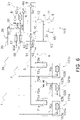
- Fig. 1 is a schematic diagram of an air conditioner 1 according to an embodiment of the present disclosure.
- the air conditioner 1 includes the following components that constitute a refrigerant circuit 30: plural use-side units 101a, 101b, and 101c, a heat-source-side unit 110, a control unit 120, and branch units 70a, 70b, and 70c.
- the air conditioner 1 is designed such that whether to perform a cooling operation (first operation) or a heating operation (second operation) can be freely selected for each individual use-side unit.
- the air conditioner 1 performs a two-stage compression refrigeration cycle by use of a refrigerant that works in the supercritical region (which in this example is a CO2 refrigerant or a CO2 refrigerant mixture).
- the use-side units 101a, 101b, and 101c are installed on the indoor ceiling of a building or other structure such as by being embedded in or suspended from the ceiling. Alternatively, the use-side units 101a, 101b, and 101c are installed on the indoor wall such as by being mounted on the wall.
- the use-side units 101a, 101b, and 101c are connected to the heat-source-side unit 110 via the following components: a liquid-refrigerant connection pipe 2, a high/low pressure gas-refrigerant connection pipe 3, a low pressure gas-refrigerant connection pipe 4, the branch units 70a, 70b, and 70c, a first shutoff valve 90, a second shutoff valve 91, and a third shutoff valve 92.
- the use-side units 101a, 101b, and 101c constitute a part of the refrigerant circuit 30.
- the first use-side unit 101a includes a first use-side heat exchanger 102a, and a first use-side expansion mechanism 103a.
- the second use-side unit 101b includes a second use-side heat exchanger 102b, and a second use-side expansion mechanism 103b.
- the third use-side unit 101c includes a third use-side heat exchanger 102c, and a third use-side expansion mechanism 103c.
- the use-side heat exchangers 102a, 102b, and 102c are heat exchangers that exchange heat between the refrigerant and indoor air to thereby handle an indoor air-conditioning load (thermal load).
- the use-side expansion mechanisms 103a, 103b, and 103c are mechanisms for causing the refrigerant to expand.
- the use-side expansion mechanisms 103a, 103b, and 103c are each implemented by an electric expansion valve.
- the use-side units 101a, 101b, and 101c each include a use-side control unit 104 that controls operations of individual components constituting the use-side units 101a, 101b, and 101c.
- the use-side control unit 104 includes a microcomputer, and various electrical components.
- the microcomputer includes a central processing unit (CPU), a memory, and other components provided for controlling the use-side units 101a, 101b, and 101c.
- the CPU reads a program stored in the memory or other storage device, and performs a predetermined computational process in accordance with the program. Further, the CPU is capable of performing an operation in accordance with the program, such as writing the results of computation into the memory or reading information stored in the memory.
- the use-side control unit 104 is capable of exchanging a control signal or other information with the heat-source-side unit 110 via a communications line.
- the use-side control unit 104 is also capable of receiving a signal related to activation or deactivation of the air conditioner 1, a signal related to various settings, or other information transmitted from a remote control (not illustrated) used for operating the use-side units 101a, 101b, and 101c.
- the present disclosure is also applicable to an air conditioner including more than three use-side units.
- the heat-source-side unit 110 is installed on the rooftop of a building or other structure, or around a building or other structure.
- the heat-source-side unit 110 is connected to the use-side units 101a, 101b, and 101c, and constitutes a part of the refrigerant circuit 30.
- the heat-source-side unit 110 mainly includes the following components: a first compressor 11, a second compressor 12, a discharge pipe 10, a first main heat-source-side flow path 21, a second main heat-source-side flow path 22, a first heat-source-side heat exchanger 81, a second heat-source-side heat exchanger 82, a first economizer heat exchanger 61, a second economizer heat exchanger 62, a first economizer pipe 31, a second economizer pipe 32, a fourth shutoff valve 93, and an accumulator 95.
- the heat-source-side unit 110 also includes a heat-source-side control unit 111 that controls operations of individual components constituting the heat-source-side unit 110.
- the heat-source-side control unit 111 includes a microcomputer, and various electrical components.
- the microcomputer includes a central processing unit (CPU), a memory, and other components provided for controlling the heat-source-side unit 110.
- the CPU reads a program stored in the memory or other storage device, and performs a predetermined computational process in accordance with the program. Further, the CPU is capable of performing an operation in accordance with the program, such as writing the results of computation into the memory or reading information stored in the memory.
- the heat-source-side control unit 111 is capable of exchanging a control signal or other information with the use-side control unit 104 of each of the use-side units 101a, 101b, and 101c via a communications line.
- the compressors 11 and 12 include the first compressor 11, which is the compressor of the lower stage, and the second compressor 12, which is the compressor of the higher stage.
- the compressors 11 and 12 include the first compressor 11, which is a single-stage compressor that compresses low pressure refrigerant in the refrigeration cycle to an intermediate pressure in the refrigeration cycle, and the second compressor 12, which is a single-stage compressor that compresses intermediate-pressure refrigerant in the refrigeration cycle to a high pressure in the refrigeration cycle.
- Low-pressure refrigerant in the refrigeration cycle is sucked via a suction pipe 8 into the first compressor 11 of the lower stage, and compressed by the first compressor 11 to an intermediate pressure in the refrigeration cycle.
- the intermediate-pressure refrigerant in the refrigeration cycle is discharged to an intermediate refrigerant pipe 9 and then sucked into the second compressor 12 of the higher stage.
- the intermediate-pressure refrigerant in the refrigeration cycle is compressed by the second compressor 12 to a high pressure in the refrigeration cycle before being discharged to the discharge pipe 10.
- the discharge pipe 10 is a pipe to which refrigerant is discharged after being compressed by the second compressor 12 of the higher stage to a high pressure in the refrigeration cycle. As illustrated in Fig. 1 , the discharge pipe 10 branches off into the first main heat-source-side flow path 21, the second main heat-source-side flow path 22, and the high/low pressure gas-refrigerant connection pipe 3.
- the first main heat-source-side flow path 21 is a pipe that branches off from the discharge pipe 10 and connects to the liquid-refrigerant connection pipe 2.
- the first main heat-source-side flow path 21 connects the first heat-source-side heat exchanger 81 and the first economizer heat exchanger 61 in series.
- the first main heat-source-side flow path 21 branches off to the first economizer pipe 31 at a point between the first heat-source-side heat exchanger 81 and the first economizer heat exchanger 61.
- the first main heat-source-side flow path 21 is provided with a first heat-source-side expansion mechanism 24a.
- the second main heat-source-side flow path 22 is a pipe that branches off from the discharge pipe 10 and connects to the liquid-refrigerant connection pipe 2.
- the second main heat-source-side flow path 22 connects the second heat-source-side heat exchanger 82 and the second economizer heat exchanger 62 in series.
- the second main heat-source-side flow path 22 branches off to the second economizer pipe 32 at a point between the second heat-source-side heat exchanger 82 and the second economizer heat exchanger 62.
- the second main heat-source-side flow path 22 is provided with a second heat-source-side expansion mechanism 24b.
- the first heat-source-side expansion mechanism 24a and the second heat-source-side expansion mechanism 24b are each implemented by an electric expansion valve in this case.
- the first economizer pipe 31 is a pipe that branches off from the first main heat-source-side flow path 21 at a point between the first heat-source-side heat exchanger 81 and the first economizer heat exchanger 61, and extends toward the compressors 11 and 12.
- the second economizer pipe 32 is a pipe that branches off from the second main heat-source-side flow path 22 at a point between the second heat-source-side heat exchanger 82 and the second economizer heat exchanger 62, and extends toward the compressors 11 and 12.
- the first economizer pipe 31 and the second economizer pipe 32 have a common part 35.
- the common part 35 is a pipe disposed between the location of branching from the first main heat-source-side flow path 21, and the first economizer heat exchanger 61, and between the location of branching from the second main heat-source-side flow path 22, and the second economizer heat exchanger 62.
- the common part 35 is provided with an expansion mechanism 36. The refrigerant passing through the common part 35 is decompressed by the expansion mechanism 36 to an intermediate pressure in the refrigeration cycle.
- Each of the first heat-source-side heat exchanger 81 and the second heat-source-side heat exchanger 82 is a heat exchanger that functions as either a radiator or condenser for refrigerant.
- the liquid side of the first heat-source-side heat exchanger 81, and the liquid side of the second heat-source-side heat exchanger 82 are connected by the first main heat-source-side flow path 21 and the second main heat-source-side flow path 22.
- the first heat-source-side heat exchanger 81 is connected in series with the first economizer heat exchanger 61 by the first main heat-source-side flow path 21.
- the second heat-source-side heat exchanger 82 is connected in series with the second economizer heat exchanger 62 by the second main heat-source-side flow path 22.
- the first economizer heat exchanger 61 and the second economizer heat exchanger 62 are double-pipe heat exchangers or plate heat exchangers in this case. After refrigerant rejects heat in the first heat-source-side heat exchanger 81 or the second heat-source-side heat exchanger 82, the refrigerant is subcooled by further rejecting heat in the first economizer heat exchanger 61 or the second economizer heat exchanger 62.
- the refrigerant flowing in the first main heat-source-side flow path 21, and the refrigerant flowing in the first economizer pipe 31 exchange heat.
- the first economizer heat exchanger 61 is connected in series with the first heat-source-side heat exchanger 81 via the first main heat-source-side flow path 21.
- the refrigerant flowing in the second main heat-source-side flow path 22, and the refrigerant flowing in the second economizer pipe 32 exchange heat.
- the second economizer heat exchanger 62 is connected in series with the second heat-source-side heat exchanger 82 via the second main heat-source-side flow path 22.
- the control unit 120 controls the operations of individual devices constituting the air conditioner 1.
- the air conditioner 1 can be controlled by the control unit 120 to switch between a first operation, a second operation, and a third operation, which will be described later.
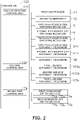
- the control unit 120 includes the following components coupled to each other via a communications line (see Fig. 2 ): the use-side control unit 104 mentioned above, the heat-source-side control unit 111 mentioned above, and a branch-side control unit 74 described later.
- Exemplary devices constituting the air conditioner 1 and controlled by the control unit 120 include the compressors 11 and 12, a first heat-source-side switching mechanism 5, a second heat-source-side switching mechanism 6, a third heat-source-side switching mechanism 7, the heat-source-side expansion mechanisms 24a and 24b, the use-side expansion mechanisms 103a, 103b, and 103c, and the branch units 70a, 70b, and 70c.
- the first heat-source-side switching mechanism 5, the second heat-source-side switching mechanism 6, and the third heat-source-side switching mechanism 7 are mechanisms for switching the directions of refrigerant flow in the refrigerant circuit 30. More specifically, these switching mechanisms are used to switch between a radiating operation state and an evaporating operation state.
- the control unit 120 determines to cause the first heat-source-side heat exchanger 81 and the second heat-source-side heat exchanger 82 to function as radiators for refrigerant.
- the control unit 120 determines to cause the first heat-source-side heat exchanger 81 and the second heat-source-side heat exchanger 82 to function as evaporators for refrigerant.
- the first heat-source-side switching mechanism 5, the second heat-source-side switching mechanism 6, and the third heat-source-side switching mechanism 7 are four-way switching valves in this case.
- a fourth port 5d of the first heat-source-side switching mechanism 5, a fourth port 6d of the second heat-source-side switching mechanism 6, and a fourth port 7d of the third heat-source-side switching mechanism 7 are closed, and thus the first heat-source-side switching mechanism 5, the second heat-source-side switching mechanism 6, and the third heat-source-side switching mechanism 7 function as three-way valves.
- the branch units 70a, 70b, and 70c are respectively installed, for example, near the use-side units 101a, 101b, and 101c in an indoor space of a building or other structure.
- the branch units 70a, 70b, and 70c are respectively interposed between the use-side units 101a, 101b, and 101c and the heat-source-side unit 110 and each constitute a part of the refrigerant circuit 30, together with the liquid-refrigerant connection pipe 2, the high/low pressure gas-refrigerant connection pipe 3, and the low pressure gas-refrigerant connection pipe 4.
- the branch units 70a, 70b, and 70c are respectively installed for the three use-side units 101a, 101b, and 101c in a one-to-one relationship.
- branch units 70a, 70b, and 70c may be respectively incorporated in the use-side units 101a, 101b, and 101c.
- the branch units 70a, 70b, and 70c can be respectively regarded as constituting portions of the use-side units 101a, 101b, and 101c.
- the branch units 70a, 70b, and 70c each mainly include a first branch path, and a second branch path.
- the respective first branch paths of the branch units 70a, 70b, and 70c include first branch-unit switching valves 71a, 72a, and 73a
- the respective second branch paths of the branch units 70a, 70b, and 70c include second branch-unit switching valves 71b, 72b, and 73b.
- the first branch-unit switching valves 71a, 72a, and 73a are electromagnetic valves for switching whether to allow communication between the high/low pressure gas-refrigerant connection pipe 3 and the use-side heat exchangers 102a, 102b, and 102c, respectively.
- the second branch-unit switching valves 71b, 72b, and 73b are electromagnetic valves for switching whether to allow communication between the low pressure gas-refrigerant connection pipe 4 and the use-side heat exchangers 102a, 102b, and 102c, respectively.
- the branch units 70a, 70b, and 70c each include the branch-side control unit 74 that controls operations of individual components constituting the branch units 70a, 70b, and 70c.
- the branch-side control unit 74 includes a microcomputer, and various electrical components.
- the microcomputer includes a central processing unit (CPU), a memory, and other components provided for controlling the branch units 70a, 70b, and 70c.
- the CPU reads a program stored in the memory or other storage device, and performs a predetermined computational process in accordance with the program. Further, the CPU is capable of performing an operation in accordance with the program, such as writing the results of computation into the memory or reading information stored in the memory.
- the branch-side control unit 74 is capable of exchanging a control signal or other information with the use-side control unit 104 of each of the use-side units 101a, 101b, and 101c.
- the air conditioner 1 according to the embodiment is switched between the first operation, the second operation, and the third operation by the control unit 120 to thereby provide air conditioning.
- the first operation is an operational state (cooling only operation) in which only use-side heat exchangers serving as evaporators for refrigerant (use-side units that perform cooling) exist.
- the second operation is an operational state (heating only operation) in which only use-side heat exchangers serving as radiators for refrigerant (use-side units that perform heating) exist.
- the third operation is an operation in which both a use-side unit that performs cooling and a use-side unit that performs heating exist (cooling and heating simultaneous operation).
- the third operation includes a third operation A, a third operation B, and a third operation C.
- the third operation A is an operational state (cooling main operation) in which although both a use-side heat exchanger serving as an evaporator for refrigerant and a use-side heat exchanger serving as a radiator for refrigerant exist, the load on the evaporation side is greater as a whole.
- the third operation B is an operational state (heating main operation) in which although both a use-side heat exchanger serving as a radiator for refrigerant and a use-side heat exchanger serving as an evaporator for refrigerant exist, the load on the radiation side is greater as a whole.
- the third operation C is an operational state (cooling and heating balanced operation) in which both a use-side heat exchanger serving as an evaporator for refrigerant and a use-side heat exchanger serving as a radiator for refrigerant exist, and the evaporation load and the radiation load are balanced as a whole.
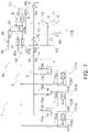
- control unit 120 causes the first use-side heat exchanger 102a and the third use-side heat exchanger 102c to function as evaporators for refrigerant to perform cooling, and deactivates the second use-side heat exchanger 102b (see Fig. 3 ).
- the control unit 120 determines to cause the first heat-source-side heat exchanger 81 and the second heat-source-side heat exchanger 82 to function as radiators for refrigerant.
- the control unit 120 switches the first heat-source-side switching mechanism 5, the second heat-source-side switching mechanism 6, and the third heat-source-side switching mechanism 7 to a radiating operation state (in which the first heat-source-side switching mechanism 5, the second heat-source-side switching mechanism 6, and the third heat-source-side switching mechanism 7 are in the state shown by solid lines in Fig. 3 ).
- the control unit 120 closes the first branch-unit switching valves 71a, 72a, and 73a and the second branch-unit switching valve 72b, and opens the second branch-unit switching valves 71b and 73b.
- the intermediate-pressure refrigerant in the refrigeration cycle After being discharged from the first compressor 11 of the lower stage to the intermediate refrigerant pipe 9, the intermediate-pressure refrigerant in the refrigeration cycle is sucked into the second compressor 12 of the higher stage, and compressed in the second compressor 12 to a high pressure in the refrigeration cycle before being discharged to the discharge pipe 10.
- the high pressure refrigerant in the refrigeration cycle discharged from the second compressor 12 of the higher stage has been compressed through the two-stage compression action of the compressors 11 and 12 to a pressure exceeding the critical pressure of the refrigerant.
- the refrigerant that has flown from the discharge pipe 10 to the first main heat-source-side flow path 21 is routed via the first heat-source-side switching mechanism 5 to the first heat-source-side heat exchanger 81.
- the high pressure refrigerant in the refrigeration cycle routed to the first heat-source-side heat exchanger 81 rejects heat through heat exchange with outdoor air or other medium in the first heat-source-side heat exchanger 81 serving as a radiator for refrigerant. After rejecting heat in the first heat-source-side heat exchanger 81, the high pressure refrigerant in the refrigeration cycle is decompressed in the first heat-source-side expansion mechanism 24a.
- the refrigerant decompressed in the first heat-source-side expansion mechanism 24a is routed to the first economizer heat exchanger 61. At this time, a part of the refrigerant decompressed in the first heat-source-side expansion mechanism 24a and flowing in the first main heat-source-side flow path 21 branches off to the first economizer pipe 31.
- the refrigerant Upon entering the common part 35, the refrigerant is decompressed by the expansion mechanism 36 of the common part 35 to an intermediate pressure in the refrigeration cycle.
- the refrigerant branches off from the common part 35 to the first economizer pipe 31 again, and then flows to the first economizer heat exchanger 61.
- the intermediate-pressure refrigerant in the refrigeration cycle exchanges heat in the first economizer heat exchanger 61 with the refrigerant flowing in the first main heat-source-side flow path 21.
- the intermediate-pressure refrigerant in the refrigeration cycle is routed via the intermediate refrigerant pipe 9 to the second compressor 12 of the higher stage.
- the refrigerant flowing in the first main heat-source-side flow path 21 that has been decompressed in the first heat-source-side expansion mechanism 24a and routed to the first economizer heat exchanger 61 is cooled in the first economizer heat exchanger 61 through heat exchange with the refrigerant flowing in the first economizer pipe 31. After being cooled in the first economizer heat exchanger 61, the refrigerant flowing in the first main heat-source-side flow path 21 is routed via the liquid-refrigerant connection pipe 2 to the use-side expansion mechanisms 103a and 103c.
- the refrigerant that has flown from the discharge pipe 10 to the second main heat-source-side flow path 22 is routed via the second heat-source-side switching mechanism 6 to the second heat-source-side heat exchanger 82.
- the high pressure refrigerant in the refrigeration cycle routed to the second heat-source-side heat exchanger 82 rejects heat through heat exchange with outdoor air or other medium in the second heat-source-side heat exchanger 82 serving as a radiator for refrigerant. After rejecting heat in the second heat-source-side heat exchanger 82, the high pressure refrigerant in the refrigeration cycle is decompressed in the second heat-source-side expansion mechanism 24b.
- the refrigerant decompressed in the second heat-source-side expansion mechanism 24b is routed to the second economizer heat exchanger 62. At this time, a part of the refrigerant decompressed in the second heat-source-side expansion mechanism 24b and flowing in the second main heat-source-side flow path 22 branches off to the second economizer pipe 32.
- the refrigerant Upon entering the common part 35, the refrigerant is decompressed by the expansion mechanism 36 of the common part 35 to an intermediate pressure in the refrigeration cycle.
- the refrigerant branches off from the common part 35 to the second economizer pipe 32 again, and then flows to the second economizer heat exchanger 62.
- the intermediate-pressure refrigerant in the refrigeration cycle exchanges heat in the second economizer heat exchanger 62 with the refrigerant flowing in the second main heat-source-side flow path 22.
- the intermediate-pressure refrigerant in the refrigeration cycle is routed via the intermediate refrigerant pipe 9 to the second compressor 12 of the higher stage.
- the refrigerant decompressed in the second heat-source-side expansion mechanism 24b and routed to the second economizer heat exchanger 62 is cooled in the second economizer heat exchanger 62 through heat exchange with the refrigerant flowing in the second economizer pipe 32. After being cooled in the second economizer heat exchanger 62, the refrigerant is routed via the liquid-refrigerant connection pipe 2 to the use-side expansion mechanisms 103a and 103c.
- the refrigerant routed via the liquid-refrigerant connection pipe 2 to the use-side expansion mechanisms 103a and 103c after undergoing heat exchange in the first economizer heat exchanger 61 and the second economizer heat exchanger 62 is decompressed in the use-side expansion mechanisms 103a and 103c and turns into low-pressure refrigerant in the refrigeration cycle that is in a two-phase gas-liquid state.
- the low pressure refrigerant in the refrigeration cycle is routed to the use-side heat exchangers 102a and 102c respectively corresponding to the use-side expansion mechanisms 103a and 103c.
- the low pressure refrigerant in the refrigeration cycle routed to the use-side heat exchangers 102a and 102c evaporates through heat exchange with indoor air or other medium in the use-side heat exchangers 102a and 102c serving as evaporators for refrigerant.
- the low pressure refrigerant in the refrigeration cycle is passed through the low pressure gas-refrigerant connection pipe 4, the accumulator 95, and the suction pipe 8 before being sucked into the first compressor 11 again. In this way, the first operation is performed.
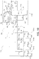
- control unit 120 causes the first use-side heat exchanger 102a and the third use-side heat exchanger 102c to function as radiators for refrigerant to perform heating, and deactivates the second use-side heat exchanger 102b (see Fig. 4 ).
- the control unit 120 determines to cause the first heat-source-side heat exchanger 81 and the second heat-source-side heat exchanger 82 to function as evaporators for refrigerant.
- the control unit 120 switches the first heat-source-side switching mechanism 5, the second heat-source-side switching mechanism 6, and the third heat-source-side switching mechanism 7 to an evaporating operation state (in which the first heat-source-side switching mechanism 5, the second heat-source-side switching mechanism 6, and the third heat-source-side switching mechanism 7 are in the state shown by solid lines in Fig. 4 ).
- the control unit 120 closes the first branch-unit switching valve 72a and the second branch-unit switching valves 71b, 72b, and 73b, and opens the first branch-unit switching valves 71a and 73a.
- the intermediate-pressure refrigerant in the refrigeration cycle After being discharged from the first compressor 11 of the lower stage to the intermediate refrigerant pipe 9, the intermediate-pressure refrigerant in the refrigeration cycle is sucked into the second compressor 12 of the higher stage, and compressed in the second compressor 12 to a high pressure in the refrigeration cycle before being discharged to the discharge pipe 10.
- the high pressure refrigerant in the refrigeration cycle discharged from the second compressor 12 of the higher stage has been compressed through the two-stage compression action of the compressors 11 and 12 to a pressure exceeding the critical pressure of the refrigerant.
- the high pressure refrigerant in the refrigeration cycle is routed via the high/low pressure gas-refrigerant connection pipe 3 and the third heat-source-side switching mechanism 7 to the use-side heat exchangers 102a and 102c.
- the high pressure refrigerant in the refrigeration cycle routed to the use-side heat exchangers 102a and 102c rejects heat through heat exchange with indoor air or other medium in the use-side heat exchangers 102a and 102c serving as radiators for refrigerant.
- the high pressure refrigerant in the refrigeration cycle is routed to the use-side expansion mechanisms 103a and 103c.
- the high pressure refrigerant in the refrigeration cycle routed to the use-side expansion mechanisms 103a and 103c is decompressed in the use-side expansion mechanisms 103a and 103c.
- the resulting refrigerant is routed via the liquid-refrigerant connection pipe 2 to the first heat-source-side expansion mechanism 24a and the second heat-source-side expansion mechanism 24b.
- the refrigerant routed to the first heat-source-side expansion mechanism 24a and the second heat-source-side expansion mechanism 24b is decompressed in the first heat-source-side expansion mechanism 24a and the second heat-source-side expansion mechanism 24b and turns into low-pressure refrigerant in the refrigeration cycle that is in a two-phase gas-liquid state.
- the low pressure refrigerant in the refrigeration cycle is routed to the first heat-source-side heat exchanger 81 and the second heat-source-side heat exchanger 82.
- the low pressure refrigerant in the refrigeration cycle routed to the first heat-source-side heat exchanger 81 and the second heat-source-side heat exchanger 82 evaporates through heat exchange with outdoor air or other medium in the first heat-source-side heat exchanger 81 and the second heat-source-side heat exchanger 82 serving evaporators for refrigerant.
- the low pressure refrigerant in the refrigeration cycle that has evaporated in the first heat-source-side heat exchanger 81 is passed through the first heat-source-side switching mechanism 5, the accumulator 95, and the suction pipe 8 before being sucked into the first compressor 11 again.
- the low pressure refrigerant in the refrigeration cycle that has evaporated in the second heat-source-side heat exchanger 82 is passed through the second heat-source-side switching mechanism 6, the accumulator 95, and the suction pipe 8 before being sucked into the first compressor 11 again. In this way, the second operation is performed.
- the third operation is now described separately for the following three types of operations: the third operation A, the third operation B, and the third operation C.
- control unit 120 causes the first use-side heat exchanger 102a and the second use-side heat exchanger 102b to function as evaporators for refrigerant to perform cooling, and causes the third use-side heat exchanger 102c to function as a radiator for refrigerant to perform heating (see Fig. 5 ).
- the control unit 120 determines to cause the first heat-source-side heat exchanger 81 and the second heat-source-side heat exchanger 82 to function as radiators for refrigerant. Further, the control unit 120 determines to cause the third use-side heat exchanger 102c to function as a radiator for refrigerant. The control unit 120 switches the first heat-source-side switching mechanism 5 and the second heat-source-side switching mechanism 6 to a radiating operation state (in which the first heat-source-side switching mechanism 5 and the second heat-source-side switching mechanism 6 are in the state shown by solid lines in Fig.
- the control unit 120 closes the first branch-unit switching valves 71a and 72a and the second branch-unit switching valve 73b, and opens the first branch-unit switching valve 73a and the second branch-unit switching valves 71b and 72b.
- the intermediate-pressure refrigerant in the refrigeration cycle After being discharged from the first compressor 11 of the lower stage to the intermediate refrigerant pipe 9, the intermediate-pressure refrigerant in the refrigeration cycle is sucked into the second compressor 12 of the higher stage, and compressed in the second compressor 12 to a high pressure in the refrigeration cycle before being discharged to the discharge pipe 10.
- the high pressure refrigerant in the refrigeration cycle discharged from the second compressor 12 of the higher stage has been compressed through the two-stage compression action of the compressors 11 and 12 to a pressure exceeding the critical pressure of the refrigerant.
- the high pressure refrigerant in the refrigeration cycle is discharged from the second compressor 12 of the higher stage, a part of the high pressure refrigerant flows from the discharge pipe 10 to the first main heat-source-side flow path 21 or the second main heat-source-side flow path 22, and the remainder is routed via the high/low pressure gas-refrigerant connection pipe 3 and the third heat-source-side switching mechanism 7 to the third use-side heat exchanger 102c.
- the refrigerant that has flown from the discharge pipe 10 to the first main heat-source-side flow path 21 is routed via the first heat-source-side switching mechanism 5 to the first heat-source-side heat exchanger 81.
- the high pressure refrigerant in the refrigeration cycle routed to the first heat-source-side heat exchanger 81 rejects heat through heat exchange with outdoor air or other medium in the first heat-source-side heat exchanger 81 serving as a radiator for refrigerant. After rejecting heat in the first heat-source-side heat exchanger 81, the high pressure refrigerant in the refrigeration cycle is decompressed in the first heat-source-side expansion mechanism 24a.
- the refrigerant decompressed in the first heat-source-side expansion mechanism 24a is routed to the first economizer heat exchanger 61. At this time, a part of the refrigerant decompressed in the first heat-source-side expansion mechanism 24a and flowing in the first main heat-source-side flow path 21 branches off to the first economizer pipe 31.
- the refrigerant Upon entering the common part 35, the refrigerant is decompressed by the expansion mechanism 36 of the common part 35 to an intermediate pressure in the refrigeration cycle.
- the refrigerant branches off from the common part 35 to the first economizer pipe 31 again, and then flows to the first economizer heat exchanger 61.
- the intermediate-pressure refrigerant in the refrigeration cycle exchanges heat in the first economizer heat exchanger 61 with the refrigerant flowing in the first main heat-source-side flow path 21.
- the intermediate-pressure refrigerant in the refrigeration cycle is routed via the intermediate refrigerant pipe 9 to the second compressor 12 of the higher stage.
- the refrigerant flowing in the first main heat-source-side flow path 21 that has been decompressed in the first heat-source-side expansion mechanism 24a and routed to the first economizer heat exchanger 61 is cooled in the first economizer heat exchanger 61 through heat exchange with the refrigerant flowing in the first economizer pipe 31. After being cooled in the first economizer heat exchanger 61, the refrigerant flowing in the first main heat-source-side flow path 21 is routed via the liquid-refrigerant connection pipe 2 to the use-side expansion mechanisms 103a and 103b.
- the refrigerant that has flown from the discharge pipe 10 to the second main heat-source-side flow path 22 is routed via the second heat-source-side switching mechanism 6 to the second heat-source-side heat exchanger 82.
- the high pressure refrigerant in the refrigeration cycle passed to the second main heat-source-side flow path 22 and then routed to the second heat-source-side heat exchanger 82 rejects heat through heat exchange with outdoor air or other medium in the second heat-source-side heat exchanger 82 serving as a radiator for refrigerant.
- the high pressure refrigerant in the refrigeration cycle is decompressed in the second heat-source-side expansion mechanism 24b.
- the refrigerant decompressed in the second heat-source-side expansion mechanism 24b is routed to the second economizer heat exchanger 62. At this time, a part of the refrigerant decompressed in the second heat-source-side expansion mechanism 24b and flowing in the second main heat-source-side flow path 22 branches off to the second economizer pipe 32.
- the refrigerant Upon entering the common part 35, the refrigerant is decompressed by the expansion mechanism 36 of the common part 35 to an intermediate pressure in the refrigeration cycle.
- the refrigerant branches off from the common part 35 to the second economizer pipe 32 again, and then flows to the second economizer heat exchanger 62.
- the intermediate-pressure refrigerant in the refrigeration cycle exchanges heat in the second economizer heat exchanger 62 with the refrigerant flowing in the second main heat-source-side flow path 22.
- the intermediate-pressure refrigerant in the refrigeration cycle is routed via the intermediate refrigerant pipe 9 to the second compressor 12 of the higher stage.
- the refrigerant decompressed in the second heat-source-side expansion mechanism 24b and routed to the second economizer heat exchanger 62 is cooled in the second economizer heat exchanger 62 through heat exchange with the refrigerant flowing in the second economizer pipe 32. After being cooled in the second economizer heat exchanger 62, the refrigerant is routed via the liquid-refrigerant connection pipe 2 to the use-side expansion mechanisms 103a and 103b.
- the high pressure refrigerant in the refrigeration cycle routed to the third use-side heat exchanger 102c rejects heat through heat exchange with indoor air or other medium in the third use-side heat exchanger 102c serving as a radiator for refrigerant.
- the high pressure refrigerant in the refrigeration cycle is routed to the third use-side expansion mechanism 103c.
- the high pressure refrigerant in the refrigeration cycle routed to the third use-side expansion mechanism 103c is decompressed in the third use-side expansion mechanism 103c.
- the refrigerant decompressed in the third use-side expansion mechanism 103c is merged in the liquid-refrigerant connection pipe 2 with the refrigerant that has undergone heat exchange in each of the first economizer heat exchanger 61 and the second economizer heat exchanger 62. After these streams of refrigerant are merged in the liquid-refrigerant connection pipe 2, the resulting merged refrigerant is routed to the use-side expansion mechanisms 103a and 103b.
- the refrigerant routed to the use-side expansion mechanisms 103a and 103b is decompressed in the use-side expansion mechanisms 103a and 103b and turns into low-pressure refrigerant in the refrigeration cycle that is in a two-phase gas-liquid state.
- the low pressure refrigerant in the refrigeration cycle is routed to the use-side heat exchangers 102a and 102b respectively corresponding to the use-side expansion mechanisms 103a and 103b.
- the low pressure refrigerant in the refrigeration cycle routed to the use-side heat exchangers 102a and 102b evaporates through heat exchange with indoor air or other medium in the use-side heat exchangers 102a and 102b serving as evaporators for refrigerant.
- the low pressure refrigerant in the refrigeration cycle is passed through the low pressure gas-refrigerant connection pipe 4, the accumulator 95, and the suction pipe 8 before being sucked into the first compressor 11 again.
- the control unit 120 may in some cases determine that the overall evaporation load on the use-side heat exchangers is small, due to reasons such as a small number of use-side heat exchangers that are acting as evaporators for refrigerant. In such cases, the control unit 120 determines to cause the first heat-source-side heat exchanger 81 to function as a radiator for refrigerant, and to cause the second heat-source-side heat exchanger 82 to function as an evaporator for refrigerant.
- the control unit 120 performs such control, the radiation load on the first heat-source-side heat exchanger 81 and the evaporation load on the second heat-source-side heat exchanger 82 are balanced out, which allows for reduced overall radiation load on the heat-source-side heat exchangers (see Fig. 6 ).
- the control unit 120 switches the first heat-source-side switching mechanism 5 to a radiating operation state (in which the first heat-source-side switching mechanism 5 is in the state shown by solid lines in Fig. 6 ), and switches the second heat-source-side switching mechanism 6 and the third heat-source-side switching mechanism 7 to an evaporating operation state (in which the second heat-source-side switching mechanism 6 and the third heat-source-side switching mechanism 7 are in the state shown by solid lines in Fig. 6 ).
- the refrigerant passed to the first main heat-source-side flow path 21 is routed to the first heat-source-side heat exchanger 81 serving as a radiator for refrigerant, and undergoes heat exchange in the first heat-source-side heat exchanger 81.
- the refrigerant After undergoing heat exchange in the first heat-source-side heat exchanger 81, the refrigerant is routed to the first heat-source-side expansion mechanism 24a, and decompressed in the first heat-source-side expansion mechanism 24a.
- a part of the refrigerant decompressed in the first heat-source-side expansion mechanism 24a flows to the first economizer pipe 31, and the remainder is routed to the first economizer heat exchanger 61.
- the refrigerant Upon entering the common part 35, the refrigerant is decompressed by the expansion mechanism 36 of the common part 35 to an intermediate pressure in the refrigeration cycle.
- the refrigerant branches off from the common part 35 to the first economizer pipe 31 again, and then flows to the first economizer heat exchanger 61.
- the intermediate-pressure refrigerant in the refrigeration cycle exchanges heat in the first economizer heat exchanger 61 with the refrigerant flowing in the first main heat-source-side flow path 21.
- the intermediate-pressure refrigerant in the refrigeration cycle is routed via the intermediate refrigerant pipe 9 to the second compressor 12 of the higher stage.
- the refrigerant flowing in the first main heat-source-side flow path 21 that has been decompressed in the first heat-source-side expansion mechanism 24a and routed to the first economizer heat exchanger 61 is cooled in the first economizer heat exchanger 61 through heat exchange with the refrigerant flowing in the first economizer pipe 31.
- a part of the refrigerant flowing in the first main heat-source-side flow path 21 after undergoing heat exchange in the first economizer heat exchanger 61 is routed via the liquid-refrigerant connection pipe 2 to the use-side expansion mechanisms 103a and 103b, and the remainder flows to the second main heat-source-side flow path 22.
- the refrigerant that has flown to the second main heat-source-side flow path 22 is decompressed in the second heat-source-side expansion mechanism 24b before being routed to the second heat-source-side heat exchanger 82.
- the resulting low pressure refrigerant in the refrigeration cycle evaporates through heat exchange with outdoor air or other medium in the second heat-source-side heat exchanger 82 serving as an evaporator for refrigerant.
- the low pressure refrigerant in the refrigeration cycle that has evaporated in the second heat-source-side heat exchanger 82 is passed through the second heat-source-side switching mechanism 6, the accumulator 95, and the suction pipe 8 before being sucked into the first compressor 11 again.
- the high pressure refrigerant routed from the discharge pipe 10 to the third use-side heat exchanger 102c rejects heat through heat exchange with indoor air or other medium in the third use-side heat exchanger 102c serving as a radiator for refrigerant.
- the high pressure refrigerant in the refrigeration cycle is routed to the third use-side expansion mechanism 103c.
- the high pressure refrigerant in the refrigeration cycle routed to the third use-side expansion mechanism 103c is decompressed in the third use-side expansion mechanism 103c.
- the refrigerant decompressed in the third use-side expansion mechanism 103c is merged in the liquid-refrigerant connection pipe 2 with the refrigerant that has undergone heat exchange in the first economizer heat exchanger 61. After these streams of refrigerant are merged in the liquid-refrigerant connection pipe 2, the resulting merged refrigerant is routed to the use-side expansion mechanisms 103a and 103b.
- the refrigerant routed to the use-side expansion mechanisms 103a and 103b is decompressed in the use-side expansion mechanisms 103a and 103b and turns into low-pressure refrigerant in the refrigeration cycle that is in a two-phase gas-liquid state.
- the low pressure refrigerant in the refrigeration cycle is routed to the use-side heat exchangers 102a and 102b respectively corresponding to the use-side expansion mechanisms 103a and 103b.
- the low pressure refrigerant in the refrigeration cycle routed to the use-side heat exchangers 102a and 102b evaporates through heat exchange with indoor air or other medium in the use-side heat exchangers 102a and 102b serving as evaporators for refrigerant.
- the low pressure refrigerant in the refrigeration cycle is passed through the low pressure gas-refrigerant connection pipe 4, the accumulator 95, and the suction pipe 8 before being sucked into the first compressor 11 again. In this way, the third operation A is performed.
- control unit 120 causes the first use-side heat exchanger 102a and the second use-side heat exchanger 102b to function as radiators for refrigerant to perform heating, and causes the third use-side heat exchanger 102c to function as an evaporator for refrigerant to perform cooling (see Fig. 7 ).
- the control unit 120 determines to cause the first heat-source-side heat exchanger 81 and the second heat-source-side heat exchanger 82 to function as evaporators for refrigerant.
- the control unit 120 switches the first heat-source-side switching mechanism 5, the second heat-source-side switching mechanism 6, and the third heat-source-side switching mechanism 7 to an evaporating operation state (in which the first heat-source-side switching mechanism 5, the second heat-source-side switching mechanism 6, and the third heat-source-side switching mechanism 7 are in the state shown by solid lines in Fig. 7 ).
- the control unit 120 closes the first branch-unit switching valve 73a and the second branch-unit switching valves 71b and 72b, and opens the first branch-unit switching valves 71a and 72a and the second branch-unit switching valve 73b.
- the intermediate-pressure refrigerant in the refrigeration cycle After being discharged from the first compressor 11 of the lower stage to the intermediate refrigerant pipe 9, the intermediate-pressure refrigerant in the refrigeration cycle is sucked into the second compressor 12 of the higher stage, and compressed in the second compressor 12 to a high pressure in the refrigeration cycle before being discharged to the discharge pipe 10.
- the high pressure refrigerant in the refrigeration cycle discharged from the second compressor 12 of the higher stage has been compressed through the two-stage compression action of the compressors 11 and 12 to a pressure exceeding the critical pressure of the refrigerant.
- the high pressure refrigerant in the refrigeration cycle is routed via the high/low pressure gas-refrigerant connection pipe 3 and the third heat-source-side switching mechanism 7 to the use-side heat exchangers 102a and 102b.
- the high pressure refrigerant in the refrigeration cycle routed to the use-side heat exchangers 102a and 102b rejects heat through heat exchange with indoor air or other medium in the use-side heat exchangers 102a and 102b serving as radiators for refrigerant.
- the high pressure refrigerant in the refrigeration cycle is routed to the use-side expansion mechanisms 103a and 103b.
- the high pressure refrigerant in the refrigeration cycle routed to the use-side expansion mechanisms 103a and 103b is decompressed in the use-side expansion mechanisms 103a and 103b.
- a part of the refrigerant is routed via the liquid-refrigerant connection pipe 2 to the first heat-source-side expansion mechanism 24a and the second heat-source-side expansion mechanism 24b, and the remainder branches off from the liquid-refrigerant connection pipe 2 and is routed to the third use-side expansion mechanism 103c.
- the refrigerant routed to the first heat-source-side expansion mechanism 24a and the second heat-source-side expansion mechanism 24b is decompressed in the first heat-source-side expansion mechanism 24a and the second heat-source-side expansion mechanism 24b and turns into low-pressure refrigerant in the refrigeration cycle that is in a two-phase gas-liquid state.
- the low pressure refrigerant in the refrigeration cycle is routed to the first heat-source-side heat exchanger 81 and the second heat-source-side heat exchanger 82.
- the low pressure refrigerant in the refrigeration cycle that has evaporated in the first heat-source-side heat exchanger 81 is passed through the first heat-source-side switching mechanism 5, the accumulator 95, and the suction pipe 8 before being sucked into the first compressor 11 again.
- the low pressure refrigerant in the refrigeration cycle that has evaporated in the second heat-source-side heat exchanger 82 is passed through the second heat-source-side switching mechanism 6, the accumulator 95, and the suction pipe 8 before being sucked into the first compressor 11 again.
- the refrigerant routed to the third use-side expansion mechanism 103c is decompressed in the third use-side expansion mechanism 103c and turns into low-pressure refrigerant in the refrigeration cycle that is in a two-phase gas-liquid state.
- the low pressure refrigerant in the refrigeration cycle is routed to the third use-side heat exchanger 102c corresponding to the third use-side expansion mechanism 103c.
- the low pressure refrigerant in the refrigeration cycle routed to the third use-side heat exchanger 102c evaporates through heat exchange with indoor air or other medium in the third use-side heat exchanger 102c serving as an evaporator for refrigerant.
- the low pressure refrigerant in the refrigeration cycle is routed via the low pressure gas-refrigerant connection pipe 4, the accumulator 95, and the suction pipe 8 to the first compressor 11.
- control unit 120 causes the first use-side heat exchanger 102a to function as a radiator for refrigerant to perform heating, deactivates the second use-side heat exchanger 102b, and causes the third use-side heat exchanger 102c to function as an evaporator for refrigerant to perform cooling (see Fig. 8 ).
- the control unit 120 determines that the first heat-source-side heat exchanger 81 and the second heat-source-side heat exchanger 82 respectively have a small radiation load and a small evaporation load.
- the control unit 120 switches the first heat-source-side switching mechanism 5 to a radiating operation state shown by solid lines in Fig. 8 , and switches the second heat-source-side switching mechanism 6 and the third heat-source-side switching mechanism 7 to an evaporating operation state shown by solid lines in Fig. 8 .
- the control unit 120 closes the first branch-unit switching valves 72a and 73a and the second branch-unit switching valves 71b and 72b, and opens the first branch-unit switching valve 71a and the second branch-unit switching valve 73b.
- the intermediate-pressure refrigerant in the refrigeration cycle discharged from the first compressor 11 of the lower stage is compressed in the second compressor 12 of the higher stage to a high pressure in the refrigeration cycle, and then discharged from the second compressor 12 of the higher stage to the discharge pipe 10.
- the high pressure refrigerant in the refrigeration cycle discharged from the second compressor 12 of the higher stage has been compressed through the two-stage compression action of the compressors 11 and 12 to a pressure exceeding the critical pressure of the refrigerant.
- the high pressure refrigerant in the refrigeration cycle is discharged to the discharge pipe 10 from the second compressor 12 of the higher stage, a part of the high pressure refrigerant is routed to the first heat-source-side heat exchanger 81, and the remainder is routed to the first use-side heat exchanger 102a.
- the high pressure refrigerant in the refrigeration cycle routed to the first heat-source-side heat exchanger 81 rejects heat through heat exchange with outdoor air or other medium in the first heat-source-side heat exchanger 81 serving as a radiator for refrigerant.
- the high pressure refrigerant in the refrigeration cycle is decompressed in the first heat-source-side expansion mechanism 24a.
- the refrigerant decompressed in the first heat-source-side expansion mechanism 24a is routed to the first economizer heat exchanger 61. At this time, a part of the refrigerant decompressed in the first heat-source-side expansion mechanism 24a and flowing in the first main heat-source-side flow path 21 branches off to the first economizer pipe 31.
- the refrigerant Upon entering the common part 35, the refrigerant is decompressed by the expansion mechanism 36 of the common part 35 to an intermediate pressure in the refrigeration cycle.
- the refrigerant branches off from the common part 35 to the first economizer pipe 31 again, and then flows to the first economizer heat exchanger 61.
- the intermediate-pressure refrigerant in the refrigeration cycle exchanges heat in the first economizer heat exchanger 61 with the refrigerant flowing in the first main heat-source-side flow path 21.
- the intermediate-pressure refrigerant in the refrigeration cycle is routed via the intermediate refrigerant pipe 9 to the second compressor 12 of the higher stage.
- the refrigerant flowing in the first main heat-source-side flow path 21 that has been decompressed in the first heat-source-side expansion mechanism 24a and routed to the first economizer heat exchanger 61 is cooled in the first economizer heat exchanger 61 through heat exchange with the refrigerant flowing in the first economizer pipe 31.
- the refrigerant flowing in the first main heat-source-side flow path 21 after being cooled in the first economizer heat exchanger 61 flows to the second main heat-source-side flow path 22, and is routed to the second heat-source-side expansion mechanism 24b.
- the refrigerant routed to the second heat-source-side expansion mechanism 24b is decompressed in the second heat-source-side expansion mechanism 24b and turns into low-pressure refrigerant in the refrigeration cycle that is in a two-phase gas-liquid state.
- the low pressure refrigerant in the refrigeration cycle is routed to the second heat-source-side heat exchanger 82.
- the low pressure refrigerant routed to the second heat-source-side heat exchanger 82 evaporates through heat exchange with outdoor air or other medium in the second heat-source-side heat exchanger 82 serving as an evaporator for refrigerant.
- the low pressure refrigerant in the refrigeration cycle that has evaporated in the second heat-source-side heat exchanger 82 is passed through the second heat-source-side switching mechanism 6, the accumulator 95, and the suction pipe 8 before being sucked into the first compressor 11.
- the high pressure refrigerant routed from the discharge pipe 10 to the first use-side heat exchanger 102a rejects heat through heat exchange with indoor air or other medium in the first use-side heat exchanger 102a serving as a radiator for refrigerant.
- the high pressure refrigerant in the refrigeration cycle is routed to the first use-side expansion mechanism 103a.
- the high pressure refrigerant in the refrigeration cycle routed to the first use-side expansion mechanism 103a is decompressed in the first use-side expansion mechanism 103a.
- the refrigerant After being decompressed in the first use-side expansion mechanism 103a, the refrigerant is routed via the liquid-refrigerant connection pipe 2 to the third use-side expansion mechanism 103c.
- the refrigerant routed to the third use-side expansion mechanism 103c is decompressed in the third use-side expansion mechanism 103c and turns into low-pressure refrigerant in the refrigeration cycle that is in a two-phase gas-liquid state.
- the low pressure refrigerant in the refrigeration cycle After being decompressed in the third use-side expansion mechanism 103c, the low pressure refrigerant in the refrigeration cycle is routed to the third use-side heat exchanger 102c.
- the low pressure refrigerant in the refrigeration cycle routed to the third use-side heat exchanger 102c evaporates through heat exchange with indoor air or other medium in the third use-side heat exchanger 102c serving as an evaporator for refrigerant.
- the low pressure refrigerant in the refrigeration cycle is passed through the low pressure gas-refrigerant connection pipe 4, the accumulator 95, and the suction pipe 8 and sucked into the first compressor 11. In this way, the third operation C is performed.
- the control unit 120 may in some cases determine that the overall evaporation load on the use-side heat exchangers is small, due to reasons such as a small number of use-side heat exchangers that are acting as evaporators for refrigerant. In such cases, the control unit 120 causes the first heat-source-side heat exchanger 81 to function as a radiator for refrigerant, and causes the second heat-source-side heat exchanger 82 to function as an evaporator for refrigerant so that the radiation load on the first heat-source-side heat exchanger 81 and the evaporation load on the second heat-source-side heat exchanger 82 are balanced out. In this way, the control unit 120 performs an operation for reducing the overall radiation load on the heat-source-side heat exchangers.
- the control unit 120 determines that the first heat-source-side heat exchanger 81 and the second heat-source-side heat exchanger 82 respectively have a small radiation load and a small evaporation load.
- the control unit 120 causes the first heat-source-side heat exchanger 81 to function as a radiator for refrigerant, and causes the second heat-source-side heat exchanger 82 to function as an evaporator for refrigerant so that the radiation load on the first heat-source-side heat exchanger 81 and the evaporation load on the second heat-source-side heat exchanger 82 are balanced out.
- the air conditioner may sometimes operate such that a part or all of refrigerant that has passed through one heat-source-side heat exchanger serving as a radiator flows to another heat-source-side heat exchanger serving as an evaporator, and the remainder of the refrigerant flows to a use-side unit.
- the air conditioner with plural heat-source-side heat exchangers is able to handle a small thermal load for the heat-source-side heat exchangers as a whole during the cooling and heating simultaneous operation.
- Some multi-split air conditioners with plural heat-source-side heat exchangers and plural use-side units in the related art are designed such that whether to perform a cooling operation or a heating operation can be freely selected for each individual use-side unit.
- One conceivable way to improve the operating efficiency of such an air conditioner is to employ a configuration in which separate streams of refrigerant that have undergone heat exchange in plural heat-source-side heat exchangers 181 and 182 are merged before undergoing heat exchange in a single economizer heat exchanger 161 (see Fig. 9 ).
- an air conditioner employing the above-mentioned configuration is to perform the operation described above in the section (3-3-1-1)
- a part of the refrigerant that passes through one heat-source-side heat exchanger serving as a radiator for refrigerant and is then routed to a use-side unit flows through an economizer heat exchanger.
- the refrigerant that passes through one heat-source-side heat exchanger serving as a radiator for refrigerant and is then routed to another heat-source-side heat exchanger does not flow through an economizer heat exchanger.
- the refrigerant having passed through one heat-source-side heat exchanger serving as a radiator for refrigerant is routed to another heat-source-side heat exchanger serving as an evaporator for refrigerant. Consequently, such refrigerant does not flow through an economizer heat exchanger.
- the first economizer heat exchanger 61 is connected in series with the first heat-source-side heat exchanger 81, and the second economizer heat exchanger 62 is connected in series with the second heat-source-side heat exchanger 82.
- the air conditioner 1 employs the above-mentioned configuration so that the refrigerant flowing in the first main heat-source-side flow path 21 passes through the first heat-source-side heat exchanger 81 and the first economizer heat exchanger 61 before flowing to the use-side units 101a and 101b or to the second heat-source-side heat exchanger 82. This ensures that in performing the cooling and heating simultaneous operation as described above in the section (3-3-1-1) or (3-3-3), sufficient heat exchange takes place in the economizer heat exchangers 61 and 62.
- the first heat-source-side heat exchanger 81 and the second heat-source-side heat exchanger 82 are caused to function as radiators.
- the first economizer heat exchanger 61 is connected in series with the first heat-source-side heat exchanger 81
- the second economizer heat exchanger 62 is connected in series with the second heat-source-side heat exchanger 82.
- the air conditioner 1 employs the above-mentioned configuration to ensure that in performing the first operation or the third operation A, the refrigerant that has rejected heat in the first heat-source-side heat exchanger 81 or the second heat-source-side heat exchanger 82 passes through the first economizer heat exchanger 61 or the second economizer heat exchanger 62. As a result, sufficient heat exchange takes place in the economizer heat exchangers 61 and 62.
- the air conditioner 1 performs a supercritical refrigeration cycle.
- the two-stage compression preferably involves injecting cooled refrigerant to each compressor.
- the first economizer heat exchanger 61 is connected in series with the first heat-source-side heat exchanger 81
- the second economizer heat exchanger 62 is connected in series with the second heat-source-side heat exchanger 82.
- the common part 35 is disposed between the location of branching from the first main heat-source-side flow path 21, and the first economizer heat exchanger 61, and between the location of branching from the second main heat-source-side flow path 22, and the second economizer heat exchanger 62. This allows two-stage compression to be efficiently performed in the compressors 11 and 12 of the air conditioner 1 that performs a supercritical refrigeration cycle.
- the common part 35 is positioned as described above, and the common part 35 is provided with the expansion mechanism 36. This configuration allows for cost reduction compared to a configuration in which each of the first economizer pipe 31 and the second economizer pipe 32 individually has an expansion mechanism and individually returns to the compressors 11 and 12.
- the compressors 11 and 12 are two compressors with a single-stage compression structure that are connected in series.
- the compressors according to the present disclosure may not necessarily have the above-mentioned configuration.
- the compressors according to the present disclosure may have a two-stage compression structure such that the two compressors 11 and 12 are incorporated in a single casing.
- the compressors 11 and 12 are two compressors with a single-stage compression structure that are connected in series.
- the compressors according to the present disclosure may not necessarily have the above-mentioned configuration.
- a single compressor 11a with a single-stage compression structure may be used that has an injection port through which intermediate-pressure refrigerant can be introduced to some point in the compression process.
- the intermediate-pressure refrigerant in the refrigeration cycle flowing in the first economizer pipe 31 and the second economizer pipe 32 undergoes heat exchange in the first economizer heat exchanger 61 and the second economizer heat exchanger 62 before being routed via the injection port to the single compressor 11a with a single-stage compression structure (see Fig. 10 ).
- the heat-source-side unit 110 includes two heat-source-side heat exchanger 81 and 82, and two economizer heat exchangers 61 and 62 respectively corresponding to the heat-source-side heat exchangers 81 and 82.
- the heat-source-side unit 110 according to the present disclosure may not necessarily include two heat-source-side heat exchangers and two economizer heat exchangers.
- the heat-source-side unit 110 may include a greater number of heat-source-side heat exchangers, and a number of economizer heat exchangers corresponding to the number of heat-source-side heat exchangers.
- the heat-source-side unit 110 of an air conditioner 1 includes two heat-source-side heat exchanger 81 and 82, and two economizer heat exchangers 61 and 62 respectively corresponding to the heat-source-side heat exchangers 81 and 82.
- the heat-source-side heat exchangers and the economizer heat exchangers according to the present disclosure may not necessarily be configured as described above.
- a single economizer heat exchanger 63 may have a number of high-pressure flow paths equal to the number of heat-source-side heat exchangers, and a single low-pressure flow path.
- the single economizer heat exchanger 63 has two high-pressure flow paths, and a single low-pressure flow path (see Fig. 11 ).
- the single economizer heat exchanger 63 serves as a first economizer heat exchanger 63a and a second economizer heat exchanger 63b.
- the first economizer pipe 31 and the second economizer pipe 32 are merged in the common part 35, and the resulting merged economizer pipe returns to the compressors 11 and 12.
- the first heat-source-side switching mechanism 5, the second heat-source-side switching mechanism 6, and the third heat-source-side switching mechanism 7 are four-way switching valves.
- four-way switching valves may not necessarily be used as flow switching valves.
- other switching valves such as electromagnetic valves, electric valves, three-way valves, or five-way valves may be used as flow switching valves.
Landscapes
- Engineering & Computer Science (AREA)
- Mechanical Engineering (AREA)
- General Engineering & Computer Science (AREA)
- Physics & Mathematics (AREA)
- Thermal Sciences (AREA)
- Chemical & Material Sciences (AREA)
- Combustion & Propulsion (AREA)
- Signal Processing (AREA)
- Fuzzy Systems (AREA)
- Mathematical Physics (AREA)
- Compression-Type Refrigeration Machines With Reversible Cycles (AREA)
- Air Conditioning Control Device (AREA)
Applications Claiming Priority (2)
| Application Number | Priority Date | Filing Date | Title |
|---|---|---|---|
| JP2019180831A JP7343764B2 (ja) | 2019-09-30 | 2019-09-30 | 空気調和機 |
| PCT/JP2020/036083 WO2021065677A1 (fr) | 2019-09-30 | 2020-09-24 | Climatiseur |
Publications (3)
| Publication Number | Publication Date |
|---|---|
| EP4033175A1 true EP4033175A1 (fr) | 2022-07-27 |
| EP4033175A4 EP4033175A4 (fr) | 2022-10-26 |
| EP4033175B1 EP4033175B1 (fr) | 2026-02-11 |
Family
ID=75270582
Family Applications (1)
| Application Number | Title | Priority Date | Filing Date |
|---|---|---|---|
| EP20872043.3A Active EP4033175B1 (fr) | 2019-09-30 | 2020-09-24 | Climatiseur |
Country Status (5)
| Country | Link |
|---|---|
| US (1) | US12253277B2 (fr) |
| EP (1) | EP4033175B1 (fr) |
| JP (1) | JP7343764B2 (fr) |
| CN (1) | CN114450543B (fr) |
| WO (1) | WO2021065677A1 (fr) |
Families Citing this family (1)
| Publication number | Priority date | Publication date | Assignee | Title |
|---|---|---|---|---|
| KR20240164232A (ko) | 2023-05-12 | 2024-11-19 | 엘지전자 주식회사 | 공기조화기 |
Family Cites Families (16)
| Publication number | Priority date | Publication date | Assignee | Title |
|---|---|---|---|---|
| JP4165566B2 (ja) * | 2006-01-25 | 2008-10-15 | ダイキン工業株式会社 | 空気調和装置 |
| JP5055965B2 (ja) * | 2006-11-13 | 2012-10-24 | ダイキン工業株式会社 | 空気調和装置 |
| JP5239824B2 (ja) | 2008-02-29 | 2013-07-17 | ダイキン工業株式会社 | 冷凍装置 |
| JP5277854B2 (ja) | 2008-10-14 | 2013-08-28 | ダイキン工業株式会社 | 空気調和装置 |
| JP5332604B2 (ja) | 2008-12-26 | 2013-11-06 | ダイキン工業株式会社 | 冷暖同時運転型空気調和装置 |
| CN102713461B (zh) | 2009-12-28 | 2015-06-10 | 大金工业株式会社 | 热泵系统 |
| WO2011080804A1 (fr) * | 2009-12-28 | 2011-07-07 | ダイキン工業株式会社 | Système de distribution au prorata de la consommation d'énergie d'une unité source de chaleur |
| JP5257491B2 (ja) * | 2011-06-30 | 2013-08-07 | ダイキン工業株式会社 | 冷凍装置の室外機 |
| CN102679609A (zh) * | 2012-06-07 | 2012-09-19 | 四川同达博尔置业有限公司 | 风冷热泵空调 |
| JP5976459B2 (ja) * | 2012-08-27 | 2016-08-23 | 三菱重工業株式会社 | 空気調和装置 |
| JP6331768B2 (ja) | 2014-06-27 | 2018-05-30 | ダイキン工業株式会社 | 冷暖同時運転型空気調和装置 |
| CN204214165U (zh) * | 2014-10-23 | 2015-03-18 | 堃霖冷冻机械(上海)有限公司 | 一种低温环境用空调冷热水机组 |
| JP6160725B1 (ja) * | 2016-02-29 | 2017-07-12 | ダイキン工業株式会社 | 冷凍装置 |
| WO2019049746A1 (fr) * | 2017-09-05 | 2019-03-14 | ダイキン工業株式会社 | Système de climatisation et unité d'embranchement pour réfrigérant |
| JP7182361B2 (ja) * | 2017-12-25 | 2022-12-02 | ダイキン工業株式会社 | 冷凍装置 |
| WO2020039707A1 (fr) * | 2018-08-22 | 2020-02-27 | 日立ジョンソンコントロールズ空調株式会社 | Dispositif à cycle frigorifique et procédé de gestion de température de fluide frigorigène dans un dispositif à cycle frigorifique |
-
2019
- 2019-09-30 JP JP2019180831A patent/JP7343764B2/ja active Active
-
2020
- 2020-09-24 EP EP20872043.3A patent/EP4033175B1/fr active Active
- 2020-09-24 CN CN202080068361.3A patent/CN114450543B/zh active Active
- 2020-09-24 WO PCT/JP2020/036083 patent/WO2021065677A1/fr not_active Ceased
-
2022
- 2022-03-25 US US17/704,250 patent/US12253277B2/en active Active
Also Published As
| Publication number | Publication date |
|---|---|
| WO2021065677A1 (fr) | 2021-04-08 |
| EP4033175B1 (fr) | 2026-02-11 |
| JP2021055960A (ja) | 2021-04-08 |
| CN114450543B (zh) | 2023-11-17 |
| CN114450543A (zh) | 2022-05-06 |
| US12253277B2 (en) | 2025-03-18 |
| US20220214056A1 (en) | 2022-07-07 |
| JP7343764B2 (ja) | 2023-09-13 |
| EP4033175A4 (fr) | 2022-10-26 |
Similar Documents
| Publication | Publication Date | Title |
|---|---|---|
| KR100504509B1 (ko) | 차단 가능한 다중 분배기를 갖는 냉난방 동시형멀티공기조화기 | |
| KR100463548B1 (ko) | 공기조화기용 제상장치 | |
| US9791193B2 (en) | Air conditioner and method of controlling the same | |
| JP5332604B2 (ja) | 冷暖同時運転型空気調和装置 | |
| KR100459137B1 (ko) | 냉난방 동시형 멀티공기조화기 | |
| KR100504498B1 (ko) | 공기조화기용 과냉확보장치 | |
| KR100499507B1 (ko) | 멀티공기조화기 | |
| KR100195913B1 (ko) | 다실 공기조화기 | |
| KR100499506B1 (ko) | 멀티공기조화기용 이물질 차단장치 | |
| EP2584285B1 (fr) | Dispositif de climatisation à réfrigération | |
| KR20180093570A (ko) | 공기조화기 | |
| US12163712B2 (en) | Air conditioner | |
| EP4033175B1 (fr) | Climatiseur | |
| WO2021005737A1 (fr) | Unité extérieure et appareil de climatisation | |
| KR100526204B1 (ko) | 공기조화장치 | |
| US11397015B2 (en) | Air conditioning apparatus | |
| CN110234938B (zh) | 空调器的室外系统 | |
| KR100504499B1 (ko) | 냉난방 동시형 멀티공기조화기용 응축액 제거장치 | |
| JP2009204243A (ja) | 冷凍装置 | |
| KR20180123270A (ko) | 공기조화기 | |
| JPH10238882A (ja) | マルチ型空気調和機の運転方法 |
Legal Events
| Date | Code | Title | Description |
|---|---|---|---|
| STAA | Information on the status of an ep patent application or granted ep patent |
Free format text: STATUS: THE INTERNATIONAL PUBLICATION HAS BEEN MADE |
|
| PUAI | Public reference made under article 153(3) epc to a published international application that has entered the european phase |
Free format text: ORIGINAL CODE: 0009012 |
|
| STAA | Information on the status of an ep patent application or granted ep patent |
Free format text: STATUS: REQUEST FOR EXAMINATION WAS MADE |
|
| 17P | Request for examination filed |
Effective date: 20220422 |
|
| AK | Designated contracting states |
Kind code of ref document: A1 Designated state(s): AL AT BE BG CH CY CZ DE DK EE ES FI FR GB GR HR HU IE IS IT LI LT LU LV MC MK MT NL NO PL PT RO RS SE SI SK SM TR |
|
| A4 | Supplementary search report drawn up and despatched |
Effective date: 20220928 |
|
| RIC1 | Information provided on ipc code assigned before grant |
Ipc: F25B 41/24 20210101ALI20220922BHEP Ipc: F25B 6/02 20060101ALI20220922BHEP Ipc: F25B 5/02 20060101ALI20220922BHEP Ipc: F25B 39/00 20060101ALI20220922BHEP Ipc: F25B 29/00 20060101ALI20220922BHEP Ipc: F25B 25/00 20060101ALI20220922BHEP Ipc: F24F 3/06 20060101ALI20220922BHEP Ipc: F25B 13/00 20060101ALI20220922BHEP Ipc: F25B 1/10 20060101ALI20220922BHEP Ipc: F24F 11/86 20180101ALI20220922BHEP Ipc: F24F 11/65 20180101ALI20220922BHEP Ipc: F25B 1/00 20060101AFI20220922BHEP |
|
| DAV | Request for validation of the european patent (deleted) | ||
| DAX | Request for extension of the european patent (deleted) | ||
| RAP3 | Party data changed (applicant data changed or rights of an application transferred) |
Owner name: DAIKIN INDUSTRIES, LTD. |
|
| P01 | Opt-out of the competence of the unified patent court (upc) registered |
Effective date: 20230525 |
|
| STAA | Information on the status of an ep patent application or granted ep patent |
Free format text: STATUS: EXAMINATION IS IN PROGRESS |
|
| 17Q | First examination report despatched |
Effective date: 20230809 |
|
| GRAP | Despatch of communication of intention to grant a patent |
Free format text: ORIGINAL CODE: EPIDOSNIGR1 |
|
| STAA | Information on the status of an ep patent application or granted ep patent |
Free format text: STATUS: GRANT OF PATENT IS INTENDED |
|
| INTG | Intention to grant announced |
Effective date: 20250916 |
|
| GRAS | Grant fee paid |
Free format text: ORIGINAL CODE: EPIDOSNIGR3 |
|
| GRAA | (expected) grant |
Free format text: ORIGINAL CODE: 0009210 |
|
| STAA | Information on the status of an ep patent application or granted ep patent |
Free format text: STATUS: THE PATENT HAS BEEN GRANTED |
|
| AK | Designated contracting states |
Kind code of ref document: B1 Designated state(s): AL AT BE BG CH CY CZ DE DK EE ES FI FR GB GR HR HU IE IS IT LI LT LU LV MC MK MT NL NO PL PT RO RS SE SI SK SM TR |
|
| REG | Reference to a national code |
Ref country code: CH Ref legal event code: F10 Free format text: ST27 STATUS EVENT CODE: U-0-0-F10-F00 (AS PROVIDED BY THE NATIONAL OFFICE) Effective date: 20260211 Ref country code: GB Ref legal event code: FG4D |
|
| REG | Reference to a national code |
Ref country code: DE Ref legal event code: R096 Ref document number: 602020066836 Country of ref document: DE |
|
| REG | Reference to a national code |
Ref country code: IE Ref legal event code: FG4D |