EP4033227A1 - Procédé de détection optique de défauts des articles en céramique - Google Patents
Procédé de détection optique de défauts des articles en céramique Download PDFInfo
- Publication number
- EP4033227A1 EP4033227A1 EP22152430.9A EP22152430A EP4033227A1 EP 4033227 A1 EP4033227 A1 EP 4033227A1 EP 22152430 A EP22152430 A EP 22152430A EP 4033227 A1 EP4033227 A1 EP 4033227A1
- Authority
- EP
- European Patent Office
- Prior art keywords
- ceramic
- ceramic article
- defects
- images
- article
- Prior art date
- Legal status (The legal status is an assumption and is not a legal conclusion. Google has not performed a legal analysis and makes no representation as to the accuracy of the status listed.)
- Withdrawn
Links
- 239000000919 ceramic Substances 0.000 title claims abstract description 137
- 230000007547 defect Effects 0.000 title claims abstract description 48
- 238000001514 detection method Methods 0.000 title claims abstract description 39
- 230000003287 optical effect Effects 0.000 title claims abstract description 31
- 238000000034 method Methods 0.000 title claims abstract description 23
- 238000011156 evaluation Methods 0.000 claims abstract description 32
- 238000001454 recorded image Methods 0.000 claims abstract description 4
- 230000005855 radiation Effects 0.000 claims description 18
- 238000003708 edge detection Methods 0.000 claims description 5
- 230000004888 barrier function Effects 0.000 claims description 2
- 230000002950 deficient Effects 0.000 claims description 2
- 229910052573 porcelain Inorganic materials 0.000 claims description 2
- 238000005286 illumination Methods 0.000 description 12
- 230000032258 transport Effects 0.000 description 7
- 238000007689 inspection Methods 0.000 description 2
- 238000004519 manufacturing process Methods 0.000 description 2
- 238000005259 measurement Methods 0.000 description 2
- 239000004065 semiconductor Substances 0.000 description 2
- 230000000007 visual effect Effects 0.000 description 2
- 230000006399 behavior Effects 0.000 description 1
- 239000003086 colorant Substances 0.000 description 1
- 238000002845 discoloration Methods 0.000 description 1
- 238000003384 imaging method Methods 0.000 description 1
- 235000020061 kirsch Nutrition 0.000 description 1
- 239000011159 matrix material Substances 0.000 description 1
- 238000003908 quality control method Methods 0.000 description 1
- 230000000630 rising effect Effects 0.000 description 1
- 230000001360 synchronised effect Effects 0.000 description 1
Images

Classifications
-
- G—PHYSICS
- G01—MEASURING; TESTING
- G01N—INVESTIGATING OR ANALYSING MATERIALS BY DETERMINING THEIR CHEMICAL OR PHYSICAL PROPERTIES
- G01N21/00—Investigating or analysing materials by the use of optical means, i.e. using sub-millimetre waves, infrared, visible or ultraviolet light
- G01N21/84—Systems specially adapted for particular applications
- G01N21/88—Investigating the presence of flaws or contamination
- G01N21/8806—Specially adapted optical and illumination features
-
- G—PHYSICS
- G01—MEASURING; TESTING
- G01N—INVESTIGATING OR ANALYSING MATERIALS BY DETERMINING THEIR CHEMICAL OR PHYSICAL PROPERTIES
- G01N21/00—Investigating or analysing materials by the use of optical means, i.e. using sub-millimetre waves, infrared, visible or ultraviolet light
- G01N21/84—Systems specially adapted for particular applications
- G01N21/88—Investigating the presence of flaws or contamination
- G01N21/8851—Scan or image signal processing specially adapted therefor, e.g. for scan signal adjustment, for detecting different kinds of defects, for compensating for structures, markings, edges
-
- G—PHYSICS
- G01—MEASURING; TESTING
- G01N—INVESTIGATING OR ANALYSING MATERIALS BY DETERMINING THEIR CHEMICAL OR PHYSICAL PROPERTIES
- G01N21/00—Investigating or analysing materials by the use of optical means, i.e. using sub-millimetre waves, infrared, visible or ultraviolet light
- G01N21/84—Systems specially adapted for particular applications
- G01N21/88—Investigating the presence of flaws or contamination
- G01N21/95—Investigating the presence of flaws or contamination characterised by the material or shape of the object to be examined
-
- G—PHYSICS
- G01—MEASURING; TESTING
- G01N—INVESTIGATING OR ANALYSING MATERIALS BY DETERMINING THEIR CHEMICAL OR PHYSICAL PROPERTIES
- G01N21/00—Investigating or analysing materials by the use of optical means, i.e. using sub-millimetre waves, infrared, visible or ultraviolet light
- G01N21/84—Systems specially adapted for particular applications
- G01N2021/845—Objects on a conveyor
Definitions
- the invention relates to a method for the optical detection of defects in ceramic articles according to the features of the preamble of claim 1.
- the WO 2010/052431 A1 shows a device for the optical inspection of labels on packages. Parcels are transported past a camera on a conveyor belt. A line scan camera is used as the camera. In order to detect any faults, polarized light is illuminated, which is guided by means of Fresnel lenses.
- the present invention is based on the object of providing a method and a device which enable faster, more precise, more reliable and more economical fault detection in the ceramic body.
- the test should deliver reproducible results and not be subject to any fluctuations in the error detection of different ceramic items.
- the object is achieved according to the invention by a method for the optical detection of defects in ceramic articles according to the features of claim 1.
- a method for the optical detection of defects in ceramic articles comprising the provision of a plurality of light sources, a camera, a conveyor unit for transporting a ceramic article to be tested, an electronic control device and an evaluation device, the light sources illuminate the ceramic article, and wherein the camera is designed as a line camera and takes a picture of a line of the ceramic article to detect defects in the ceramic article, and wherein the ceramic article is transported on the conveyor unit in such a way that the camera takes several for one picture Records rows of the ceramic article, and wherein the electronic control device controls the camera and/or the conveyor unit and the evaluation device evaluates the recorded images.
- the camera takes several pictures one after the other in different lighting situations of the article, and the electronic control device controls or switches the several light sources independently of one another in order to generate the different lighting situations of the ceramic article.
- controlling or switching independently means that only a single one of the multiple light sources illuminates the ceramic article, or that two or more, but not all, of the multiple light sources illuminate the ceramic article at the same time. Provision can also be made for several or all of the several light sources to illuminate the ceramic article in a lighting situation.
- the light sources are preferably switchable for this purpose, in particular switchable individually or switchable in groups.
- the different lighting situations of the multiple light sources make it possible to check ceramic items for defects with great precision. Due to the different lighting situations, reflections on the surface of the ceramic article can be avoided or generated, for example. It is also possible, for example, to also illuminate the flanks of the ceramic object, such as a foot. Due to the different lighting situations, even strongly curved surfaces can be checked for defects. A classification into different quality levels can thus be automated and without quality fluctuations of the test.
- the camera can preferably be designed as a CCD camera with a two-dimensional sensor.
- the camera can be designed as a line camera with a line sensor.
- a line scan camera is the fast readout time and the higher number of pixels in the line compared to cameras with two-dimensional sensors.
- Telecentric lighting of the ceramic article means that the light source is imaged on the ceramic article by means of a telecentric beam path. With telecentric lighting, the ceramic article is illuminated with parallel rays, ie the light rays hit the ceramic article at the same angle of incidence. at the diffuse illumination can be provided that several diffuse light sources are formed.
- the ceramic article is illuminated telecentrically and not detected telecentrically, or that the ceramic article is not illuminated telecentrically and is detected telecentrically, or that the ceramic article is illuminated telecentrically and is detected telecentrically.
- the ceramic articles or pieces of crockery to be tested can be fed manually or automatically, for example by a robot arm, to the conveying unit or the conveyor belt.
- the conveying unit or the conveyor belt transports the ceramic articles or crockery items to be checked past the line camera, which, controlled by the control device, takes one or more images of a part to be checked.
- the image recordings are evaluated by an evaluation device and checked for the presence of errors.
- the control device and/or evaluation device activates a visual display, for example, in order to display the error.
- control device and/or evaluation device can activate the conveyor unit in order to eject the faulty part from the product flow.
- the control device and/or evaluation device can preferably control a robot arm arranged after (downstream) the camera in order to remove a faulty part from the conveyor unit.
- the multiple radiation sources of the telecentric illumination are preferably arranged in two rows next to one another, preferably corresponding to the linear detection of the camera.
- the first row and the second row are preferably arranged at an angle to one another in order to illuminate the ceramic article in a line despite the spatial offset next to one another.
- the light source or the plurality of radiation sources has LEDs (light-emitting diodes).
- the LEDs can be switchable with regard to their intensity and/or lighting duration and/or light temperature or light color.
- the multiple radiation sources of the telecentric illumination are preferably arranged in two rows next to one another, preferably corresponding to the linear detection of the camera.
- the first row and the second row are in one Arranged at angles to each other in order to illuminate the ceramic article next to each other in a line despite the spatial offset.
- the advantage of lighting from different sides and at different angles is that strongly curved areas or rising edges can also be illuminated.
- one or more light sources have semiconductor diodes (LED) and/or gas discharge lamps as light-emitting components. Provision can be made for the light sources to emit different wavelength ranges or wavelengths. This makes it possible for the evaluation device to recognize different faults differently and to be able to clearly allocate them as a result
- At least 4 or 6 telecentric light sources illuminate the ceramic article independently of one another or together, and/or that at least 9 or 18 or 27 or 36 diffuse light sources illuminate independently of one another or together.
- the line detection range of the camera can be less than or equal to 300 ⁇ m, preferably less than or equal to 200 ⁇ m, most preferably less than or equal to 150 ⁇ m.
- the line detection area covers the width of the ceramic body completely, i.e. at the widest point, the length is limited to less than or equal to 300 ⁇ m, preferably less than or equal to 200 ⁇ m, most preferably less than or equal to 150 ⁇ m.
- the line detection area is preferably understood to mean that area of a ceramic article to be tested which is projected onto the camera sensor when an image is recorded.
- a line is imaged, a series of images with a plurality of images of the same line is recorded, with the individual images of the series of images differing in the lighting situation.
- the recording series ie the different Lighting situations are switched through so quickly that the same line, or almost the same line, is always recorded by the line camera. All lighting situations, or the lighting situations of the light sources, are preferably switched within the line detection area. Approximately means here that the article to be tested moves continuously in the direction of conveyance and thus a minimal movement of the ceramic article is present even in the case of a rapid image recording with several images.
- the multiple images of a recording series in a line are recorded so quickly one after the other that the ceramic article is transported further by less than the line recording area in the time required to record all these multiple images.
- This can be achieved by continuously transporting the ceramic article at an appropriate speed on the conveyor unit.
- the conveyor belt can transport the ceramic article in increments, with the increments being synchronized with the imaging.
- All lighting situations, or the lighting situations of the light-emitting semiconductor diodes and/or the lighting situations of the diffuse light sources, are preferably switched within a line detection range. This means that in a series of 15 images, each image has a different lighting situation.
- the line scan camera records 15 images per line, each with a different lighting situation.
- the series of recordings is repeated accordingly for the following line, so that at the end there are 15 images of the body to be examined, each with a different lighting situation, which are evaluated by an evaluation device.
- the recording of several lines and one recording series for each line can be understood as a matrix in the form of n lines with m lighting situations.
- the recording preferably starts and/or ends with a sensor, preferably a light barrier.
- the article to be checked is transported continuously by the conveyor unit.
- the transport speed is adjusted in such a way that the article to be checked is transported by less than the line detection range, preferably by less than half the line detection range, during a recording series of a line. This ensures that the multiple recordings of the line camera of a recording series each detect the same line.
- the light source can comprise a plurality of line modules arranged in rows or lines.
- the line modules can be held interchangeably on a frame.
- Each of the row modules can have a large number of LEDs arranged next to one another.
- Such a line module illuminates the body to be tested at a predetermined angle, which differs from the illumination angle of an adjacent line module.
- a line module can preferably comprise radiation sources, preferably LEDs, arranged next to one another in two lines or rows, the two lines being offset from one another by half the diameter of a radiation source.
- a multiplicity of LEDs are arranged side by side in each of the lines or rows. The LEDs are offset from one another in such a way that their radiation pattern partially overlaps in such a way that areas with different radiation intensities balance each other out. This arrangement enables a line of the body to be examined to be irradiated with constant intensity.
- the illumination of a radiation source from the second row fills in the respective illumination intensity minimum between the illumination of each radiation source in the first row.
- the light source can preferably comprise a line light source, which is arranged with its longitudinal extension transversely, ie at right angles, to the conveying direction of the conveying unit. It is also conceivable that several line light sources are provided, which are arranged at different angles relative to the conveying direction of the conveying unit.
- control device can be connected to the light source or to the multiple line modules of the light source and/or to the multiple LEDs of the light source in order to control or switch them.
- the control device can switch the LEDs individually or in groups and/or switch the line modules individually and/or in groups and/or control their light intensity and/or their lighting duration and/or their light temperature or light color.
- control device is also connected to the conveyor unit in order to transport the body to be tested synchronously with the recording.
- the evaluation device can generate an overall picture from the multiple lines of the entire ceramic article composed in order to detect defects in the ceramic article, and/or that the evaluation device for each lighting situation of the recording series from the multiple lines of the entire ceramic article puts together several overall images, each with different lighting situations, preferably in each case putting together an overall image for each lighting situation, and that the evaluating device subsequently evaluates and/or compares one or more or all of the overall images with different lighting situations in order to detect defects in the ceramic article.
- the detected errors are recorded in a memory and/or displayed optically.
- the memory can be an electronically writable non-volatile memory.
- ceramic articles recognized as defective are discharged from the conveying flow of the conveying unit, or the ceramic articles are sorted according to the detected defect.
- the conveyor unit can be in the form of a conveyor belt or a traversing table or a belt conveyor, or a transport arm, or a transport device.
- the ceramic article is removed from a conveyor belt or a traversing table or a belt belt by the transport arm before the measurement and is preferably placed on the conveyor belt or the traversing table or the belt belt after the measurement.
- the evaluation device carries out an edge detection with an overall image of the ceramic article, preferably using an edge filter or edge detector, in order to detect defects in the ceramic article and/or that the evaluation device for each of the overall images with a different lighting situation, preferably different diffuse and/or telecentric lighting situation, performs an edge detection and then compares them with each other in order to to detect defects in the ceramic article and/or to eliminate reflections on the images of the ceramic article.
- Edge detection separates two-dimensional areas in a digital image. This is done by so-called edge operators, which recognize areas that differ in color or gray value, or brightness or texture.
- edge operators are, for example, the Sobel operator, the Scharr operator, the Laplace filter or the Kirsch operator.
- the reflections or reflections on the surface of the ceramic body can preferably be eliminated by the evaluation device, i.e. the evaluation device preferably recognizes reflections or reflections by comparing several overall images and does not classify them as a defect in the ceramic article.
- the evaluation device can be trained by recording defect-free ceramic articles.
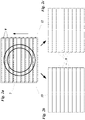
- the device 1 for carrying out the method according to the invention for the optical detection of defects in ceramic articles 2, comprising a plurality of light sources 3, a camera 4, a ceramic article 2, a conveyor unit 5, an electronic control device 6 and an evaluation device 7.
- the ceramic article 2 is transported on the conveyor unit 5 in the conveying direction (arrow in 1 ) passed under the light sources 3 and the camera 4.
- the conveyor unit 5 is designed as a conveyor belt.
- the light source 3 illuminates the ceramic article 2.
- two light sources 3 are formed, with an optical component 8, for example a lens, being arranged between the left first light source 3 and the ceramic article 2 in order to illuminate the ceramic article 2 telecentrically.
- the right second light source 3 irradiates the ceramic article 2 with diffused light.
- the two light sources 3 in 1 can be controlled separately and thereby generate different lighting situations, i.e. a first lighting situation by illuminating the ceramic article 2 with the first light source 3 and a second lighting situation by illuminating the ceramic article 2 with the second light source 3.
- the camera 4 takes pictures of the ceramic article 2 .
- the electronic control device 6 and the evaluation device 7 are in the embodiment of 1 formed in a common system and are connected to both the light source 3 and the camera 4 in order to control them and to read out images and information from the camera 4 .
- a line 9 is recorded by illuminating the first or second light source 3 and recording an image through the camera 4.
- a series of recordings of each line is recorded with two images of the same line, a first image with the first lighting situation and a second image with the second lighting situation. That is, each line 9 is recorded with the two different lighting situations, the first lighting situation by the left first light source 3 in 1 and the second lighting situation by the right second light source 3 in 1 .
- the Figure 2a the positions of the first and second image of a line correspond approximately, but have a small offset to each other, which is caused by the continuous further movement of the ceramic article in the conveying direction (arrow in Figure 2a ) arises.
- the offset of rows 9 to the left and right in Figure 2a is only schematic in order to better recognize the lines 9.
- each line 9 is recorded under different lighting situations.
- the evaluation device 7 compiles an overall image from the multiple lines and images of the entire ceramic article, the first overall image 10, which shows the entire ceramic article 2 under the first lighting situation, and the second overall image 11, which shows the entire ceramic article 2 under the represents second lighting situations.
- the evaluation device can then evaluate the first overall image 10 and the second overall image 11 separately or compare them with one another and evaluate the comparison.
Landscapes
- Physics & Mathematics (AREA)
- Health & Medical Sciences (AREA)
- Life Sciences & Earth Sciences (AREA)
- Chemical & Material Sciences (AREA)
- Analytical Chemistry (AREA)
- Biochemistry (AREA)
- General Health & Medical Sciences (AREA)
- General Physics & Mathematics (AREA)
- Immunology (AREA)
- Pathology (AREA)
- Engineering & Computer Science (AREA)
- Computer Vision & Pattern Recognition (AREA)
- Signal Processing (AREA)
- Investigating Materials By The Use Of Optical Means Adapted For Particular Applications (AREA)
- Analysing Materials By The Use Of Radiation (AREA)
- Investigating Or Analyzing Materials By The Use Of Ultrasonic Waves (AREA)
Applications Claiming Priority (1)
| Application Number | Priority Date | Filing Date | Title |
|---|---|---|---|
| DE102021101155.8A DE102021101155A1 (de) | 2021-01-20 | 2021-01-20 | Verfahren zur optischen Detektion von Fehlern in keramischen Artikeln |
Publications (1)
| Publication Number | Publication Date |
|---|---|
| EP4033227A1 true EP4033227A1 (fr) | 2022-07-27 |
Family
ID=80113203
Family Applications (1)
| Application Number | Title | Priority Date | Filing Date |
|---|---|---|---|
| EP22152430.9A Withdrawn EP4033227A1 (fr) | 2021-01-20 | 2022-01-20 | Procédé de détection optique de défauts des articles en céramique |
Country Status (2)
| Country | Link |
|---|---|
| EP (1) | EP4033227A1 (fr) |
| DE (1) | DE102021101155A1 (fr) |
Cited By (1)
| Publication number | Priority date | Publication date | Assignee | Title |
|---|---|---|---|---|
| WO2024124738A1 (fr) * | 2022-12-14 | 2024-06-20 | 宁德时代新能源科技股份有限公司 | Appareil de détection optique, procédé et appareil de détection, dispositif électronique et support de stockage |
Families Citing this family (2)
| Publication number | Priority date | Publication date | Assignee | Title |
|---|---|---|---|---|
| CN117990530B (zh) * | 2024-04-07 | 2024-05-31 | 济南哈特曼环保科技有限公司 | 植物微粒餐具生产工艺在线韧性检测方法和装置 |
| CN118067621B (zh) * | 2024-04-17 | 2024-06-25 | 常州旭焱光电科技有限公司 | 一种精密陶瓷件的生产设备及生产工艺 |
Citations (7)
| Publication number | Priority date | Publication date | Assignee | Title |
|---|---|---|---|---|
| DE3146834A1 (de) * | 1981-01-29 | 1982-09-02 | VE Wissenschaftlich-technischer Betrieb Keramik, DDR 8250 Meißen | Messvorrichtung und verfahren zur beruehrungslosen pruefung der geometrie und oberflaechenbeschaffenheit von koerpern, insbesondere feinkeramische erzeugnisse |
| EP1049925A1 (fr) | 1998-01-22 | 2000-11-08 | Applied Materials, Inc. | Procede et appareil d'inspection optique |
| CN1873295A (zh) * | 2006-05-10 | 2006-12-06 | 李贤伟 | 一种检查印刷电路板的光源装置 |
| WO2010052431A1 (fr) | 2008-11-05 | 2010-05-14 | Edixia | Dispositif pour inspecter des soudures d'emballage |
| JP2014163771A (ja) * | 2013-02-25 | 2014-09-08 | Kurabo Ind Ltd | 外観検査装置 |
| IT201600095896A1 (it) * | 2016-09-23 | 2018-03-23 | Paola Ferrari | Macchina di controllo automatica. |
| WO2020027440A1 (fr) * | 2018-08-01 | 2020-02-06 | 주식회사 뷰온 | Dispositif et procédé de vérification de défaut de surface, au moyen d'un capteur d'image |
Family Cites Families (5)
| Publication number | Priority date | Publication date | Assignee | Title |
|---|---|---|---|---|
| DE19511197C2 (de) | 1995-03-27 | 1999-05-12 | Basler Gmbh | Verfahren und Vorrichtung zum optischen Prüfen einer Oberfläche, insbesondere einer Compact-Disc |
| DE102007002106B3 (de) | 2007-01-09 | 2008-07-03 | Wolfgang Weinhold | Verfahren und Vorrichtung zur Untersuchung eines Gegenstandes |
| DE102010048804A1 (de) | 2010-10-20 | 2012-04-26 | Soft Control Gmbh Automatisierungstechnik | Verfahren zur automatischen Prüfung von halbtransparenten Objekten, insbesondere Waffeln, mit einer Kamera |
| DE102015212910A1 (de) | 2015-07-09 | 2017-01-12 | Sac Sirius Advanced Cybernetics Gmbh | Vorrichtung zur Beleuchtung von Gegenständen |
| EP3236198B1 (fr) | 2016-04-18 | 2021-03-10 | VITRONIC Dr.-Ing. Stein Bildverarbeitungssysteme GmbH | Éclairage en ligne commutable |
-
2021
- 2021-01-20 DE DE102021101155.8A patent/DE102021101155A1/de active Pending
-
2022
- 2022-01-20 EP EP22152430.9A patent/EP4033227A1/fr not_active Withdrawn
Patent Citations (7)
| Publication number | Priority date | Publication date | Assignee | Title |
|---|---|---|---|---|
| DE3146834A1 (de) * | 1981-01-29 | 1982-09-02 | VE Wissenschaftlich-technischer Betrieb Keramik, DDR 8250 Meißen | Messvorrichtung und verfahren zur beruehrungslosen pruefung der geometrie und oberflaechenbeschaffenheit von koerpern, insbesondere feinkeramische erzeugnisse |
| EP1049925A1 (fr) | 1998-01-22 | 2000-11-08 | Applied Materials, Inc. | Procede et appareil d'inspection optique |
| CN1873295A (zh) * | 2006-05-10 | 2006-12-06 | 李贤伟 | 一种检查印刷电路板的光源装置 |
| WO2010052431A1 (fr) | 2008-11-05 | 2010-05-14 | Edixia | Dispositif pour inspecter des soudures d'emballage |
| JP2014163771A (ja) * | 2013-02-25 | 2014-09-08 | Kurabo Ind Ltd | 外観検査装置 |
| IT201600095896A1 (it) * | 2016-09-23 | 2018-03-23 | Paola Ferrari | Macchina di controllo automatica. |
| WO2020027440A1 (fr) * | 2018-08-01 | 2020-02-06 | 주식회사 뷰온 | Dispositif et procédé de vérification de défaut de surface, au moyen d'un capteur d'image |
Cited By (1)
| Publication number | Priority date | Publication date | Assignee | Title |
|---|---|---|---|---|
| WO2024124738A1 (fr) * | 2022-12-14 | 2024-06-20 | 宁德时代新能源科技股份有限公司 | Appareil de détection optique, procédé et appareil de détection, dispositif électronique et support de stockage |
Also Published As
| Publication number | Publication date |
|---|---|
| DE102021101155A1 (de) | 2022-07-21 |
Similar Documents
| Publication | Publication Date | Title |
|---|---|---|
| DE3532068C2 (fr) | ||
| DE68926830T2 (de) | Verfahren und Vorrichtung zur Prüfung der Seitenwand einer Flasche | |
| DE3587927T2 (de) | Verfahren und Vorrichtung zur automatischen Untersuchung von Tabletten. | |
| DE3639636C2 (de) | Automatische Inspektion von Textilbahnen | |
| EP2801533B1 (fr) | Dispositif et procédé de fabrication d'assemblages de récipient | |
| DE2617457C3 (de) | Vorrichtung zum Prüfen von durchsichtigen, axial symmetrischen Gegenständen auf Fehler | |
| EP4033227A1 (fr) | Procédé de détection optique de défauts des articles en céramique | |
| EP3204759B1 (fr) | Dispositif d'inspection et procédé d'inspection en lumière transmise de récipients | |
| EP4033226A1 (fr) | Procédé de détection optique des défauts des articles en céramique | |
| DE112014004645T5 (de) | System und Verfahren zur Inspektion feuchter Kontaktlinsen | |
| EP1198704B1 (fr) | Procede et dispositif d'inspection de receptacles transparents | |
| EP0234492A2 (fr) | Dispositif de mesure et procédé pour la détection de surfaces différemment formées des objets | |
| DE102018202051B4 (de) | Vorrichtung zum automatischen Prüfen von Linsen und Verfahren zum automatischen Prüfen einer Vielzahl von Linsen | |
| EP2390656A2 (fr) | Dispositif et procédé de vérification optique | |
| DE10065290A1 (de) | Verfahren und Vorrichtung zur optischen Inspektion von Flaschen | |
| EP3812748B1 (fr) | Procédé et dispositif d'inspection optique de récipients | |
| DE3111194C2 (de) | Verfahren und Vorrichtung zur Feststellung von Fehlern von Glasgegenständen | |
| DE2620240A1 (de) | Verfahren und vorrichtung zur pruefung lichtundurchlaessiger werkstuecke | |
| DE3809221A1 (de) | Verfahren zum detektieren von fehlstellen an pressteilen oder anderen werkstuecken und vorrichtung zur durchfuehrung des verfahrens | |
| WO2017202954A1 (fr) | Procédé et dispositif pour examiner des produits en vrac | |
| DE102007018204B4 (de) | Vorrichtung zur Erfassung von Fehlerstellen in Tierhäuten | |
| WO2020008077A1 (fr) | Procédé et dispositif de contrôle optique de préformes | |
| DE102019125134A1 (de) | Bauteilhandhabung, Bauteilinspektion | |
| EP4033225A1 (fr) | Procede d'inspection optique de defauts dans des articles en ceramique | |
| DE3872906T2 (de) | Einrichtung zum ueberpruefen der groesse des vakuums in einem geschlossenen behaelter. |
Legal Events
| Date | Code | Title | Description |
|---|---|---|---|
| PUAI | Public reference made under article 153(3) epc to a published international application that has entered the european phase |
Free format text: ORIGINAL CODE: 0009012 |
|
| STAA | Information on the status of an ep patent application or granted ep patent |
Free format text: STATUS: THE APPLICATION HAS BEEN PUBLISHED |
|
| AK | Designated contracting states |
Kind code of ref document: A1 Designated state(s): AL AT BE BG CH CY CZ DE DK EE ES FI FR GB GR HR HU IE IS IT LI LT LU LV MC MK MT NL NO PL PT RO RS SE SI SK SM TR |
|
| STAA | Information on the status of an ep patent application or granted ep patent |
Free format text: STATUS: THE APPLICATION IS DEEMED TO BE WITHDRAWN |
|
| 18D | Application deemed to be withdrawn |
Effective date: 20230128 |