EP4033509B1 - Bedienungsanordnung und haushaltsgerät - Google Patents
Bedienungsanordnung und haushaltsgerät Download PDFInfo
- Publication number
- EP4033509B1 EP4033509B1 EP20912368.6A EP20912368A EP4033509B1 EP 4033509 B1 EP4033509 B1 EP 4033509B1 EP 20912368 A EP20912368 A EP 20912368A EP 4033509 B1 EP4033509 B1 EP 4033509B1
- Authority
- EP
- European Patent Office
- Prior art keywords
- operating portion
- operating
- assembly
- contact member
- electric signal
- Prior art date
- Legal status (The legal status is an assumption and is not a legal conclusion. Google has not performed a legal analysis and makes no representation as to the accuracy of the status listed.)
- Active
Links
Images


Classifications
-
- H—ELECTRICITY
- H01—ELECTRIC ELEMENTS
- H01H—ELECTRIC SWITCHES; RELAYS; SELECTORS; EMERGENCY PROTECTIVE DEVICES
- H01H25/00—Switches with compound movement of handle or other operating part
- H01H25/06—Operating part movable both angularly and rectilinearly, the rectilinear movement being along the axis of angular movement
-
- H—ELECTRICITY
- H01—ELECTRIC ELEMENTS
- H01H—ELECTRIC SWITCHES; RELAYS; SELECTORS; EMERGENCY PROTECTIVE DEVICES
- H01H3/00—Mechanisms for operating contacts
- H01H3/02—Operating parts, i.e. for operating driving mechanism by a mechanical force external to the switch
- H01H3/08—Turn knobs
- H01H2003/085—Retractable turn knobs, e.g. flush mounted
-
- H—ELECTRICITY
- H01—ELECTRIC ELEMENTS
- H01H—ELECTRIC SWITCHES; RELAYS; SELECTORS; EMERGENCY PROTECTIVE DEVICES
- H01H25/00—Switches with compound movement of handle or other operating part
- H01H25/06—Operating part movable both angularly and rectilinearly, the rectilinear movement being along the axis of angular movement
- H01H25/065—Operating part movable both angularly and rectilinearly, the rectilinear movement being along the axis of angular movement using separate operating parts, e.g. a push button surrounded by a rotating knob
Definitions
- the present disclosure relates to an operating assembly for a household appliance and a household appliance comprising such an operating assembly.
- DE 10 2005 045300 A1 discloses an operating device comprising an input element which switches from a first mode to a second mode via actuation of a further input element in an operation type.
- the input elements are rotary switches, pressing switches, rotary-turning switches or pressing-turning switches.
- US 2008/023313 A1 discloses a dual-concentric knob, in which an inner knob acts as a solid knob for forces below a threshold and collapses into an outer knob for forces above the threshold. In some examples the inner knob also acts as a push button for forces below the threshold.
- a hand-operated control is mounted on a hub for axial movement between a first position and a second position relative to the hub, a mechanism axially rigidly couples the control to the hub in the first position unless a force greater than a threshold is applied to the control, and a mechanism rotationally couples the control to the hub in both the first and the second positions.
- CN 209 084 831 U discloses an incremental coding type gas stove control device.
- Hollow shaft, the hollow shaft is nested on the outer wall of the gas firepower adjusting rod; a rotor of the gear motor is fixedly connected with the axis of the gas stove firepower adjusting inner rod in an aligned mode.
- the incremental encoder shell and the gear motor stator are both fixed to the inner wall of the inner lantern ring, the wire groove is formed in the inner wall of the inner lantern ring, the limiting clamp is inserted into a clamping groove of the fixing box, and a knob inner groove is formed in the lower end of the gas switch knob and installed with the upper end of the gear motor rotor in a nested mode.
- the embodiments of the present disclosure provide an operating assembly and household appliance.
- Some embodiments of the present disclosure provide an operating assembly for a household appliance.
- the operating assembly includes a first operating portion and a second operating portion.
- the first operating portion is at least partially disposed in the second operating portion.
- the second operating portion is capable of being located at a first position and a second position of the first operating portion, and capable of moving between the first position and the second position.
- the operating assembly being configured in such a manner that: when determining that the second operating portion is located at the first position, the second operating portion is rotatable relative to the first operating portion to generate a first electric signal; when determining that the second operating portion is located at the second position, the second operating portion is capable of driving the first operating portion to rotate, generating a second electric signal during the rotation of the first operating portion; and the first operating portion is capable of being pressed to generate a third electric signal.
- the operating assembly when different operations are performed on the first operating portion and the second operating portion, the operating assembly is able to output a plurality of electric signals, and the functions of the operating assembly can be multiplied by providing two operating portions, to meet the multi-functional requirements of household appliance.
- the structure is simple and easy to be implemented to improve the user convenience.
- the operating assembly further includes a coupling structure, when determining that the second operating portion is located at the second position, the second operating portion is capable of, when being rotated and by means of the coupling structure, driving the first operating portion to rotate.
- the coupling structure includes a fixture block located at either the first operating portion or the second operating portion, and a fixture seat located at an other one of either the first operating portion or the second operating portion.
- the operating assembly further includes a first elastic member, when determining that the second operating portion is located at the second position, the first elastic member abuts between the first operating portion and the second operating portion, and provides the second operating portion with a force to move from the second position to the first position.
- the operating assembly includes a first contact member mounted on the first operating portion, and a second contact member mounted on the second operating portion, when determining that the second operating portion is located at the first position, the first contact member is connected to the second contact member; when determining that the second operating portion is located at the first position and is rotated, the first contact member and the second contact member rotate relative to each other to generate the first electric signal; and when determining that the second operating portion is located at the second position, the first contact member is separated from the second contact member.
- the operating assembly includes a base, the first operating portion is movably connected to the base, and the base has an output terminal provided thereon and configured to output an electric signal of the operating assembly to a controller of the household appliance.
- the operating assembly includes a limiting structure disposed on the base.
- the first operating portion is capable of being located at a third position and a fourth position of the base, and is switchable between the third position and the fourth position; when determining that the first operating portion is located at the third position, the limiting structure is connected to the first operating portion to limit a rotation of the first operating portion; and when determining that the first operating portion is located at the fourth position, the limiting structure is separated from the first operating portion to remove the limitation on the rotation of the first operating portion, allowing the first operating portion to rotate.
- the operating assembly includes a second elastic member abutting against the base and the first operating portion.
- the operating assembly includes a switch member outputting the third electric signal in response to the first operating portion being pressed.
- the operating assembly includes an encoder connected to the first operating portion, the encoder detects a rotation angle of the first operating portion and output the second electric signal based on the rotation angle.
- Some embodiments of the present disclosure provide a household appliance.
- the household appliance includes the operating assembly as described in any of the above-mentioned embodiments, and a panel.
- the operating assembly is mounted on the panel.
- the operating assembly when different operations are performed on the first operating portion and the second operating portion, the operating assembly is able to output a plurality of electric signals, and the functions of the operating assembly can be multiplied by providing two operating portions, to meet the multi-functional requirements of household appliance.
- the structure is simple and easy to be implemented to improve the user convenience.
- household appliance 100 panel 101, opening 102, operating assembly 10, first operating portion 11, upper portion 113, middle portion 114, lower portion 115, fixture portion 116, second operating portion 12, third portion 121, protruding portion 13, recess 14, coupling structure 15, fixture block 151, fixture seat 152, first elastic member 16, first contact member 17, second contact member 18, base 19, output terminal 191, receiving space 192, limiting structure 20, limiting recess 201, second elastic member 21, switch member 22, body 221, elastic contact member 222, encoder 23, first portion 30, first notch 40, second notch 50, third notch 60.
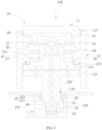
- an embodiment of the present disclosure provides an operating assembly 10 for a household appliance 100.
- the operating assembly 10 includes a first operating portion 11 and a second operating portion 12.
- the first operating portion 11 is at least partially disposed in the second operating portion 12, and the second operating portion 12 can be located at a first position ( FIG. 2 ) and a second position ( FIG. 3 ) of the first operating portion 11, and can move back and forth between the first position and the second position.
- the operating assembly 10 is configured in such a manner that, when the second operating portion 12 is located at the first position, the second operating portion 12 is rotatable relative to the first operating portion 11 to generate a first electric signal; and when the second operating portion 12 is located at the second position, the second operating portion 12 can drive the first operating portion 11 to rotate, and a second electric signal is generated during the rotation of the first operating portion 11.
- the first operating portion 11 can be pressed to generate a third electric signal.
- the operating assembly 10 when different operations are performed on the first operating portion 11 and the second operating portion 12, the operating assembly 10 can output a plurality of electric signals, and the functions of the operating assembly 10 can be multiplied by providing the two operating portions. In this way, the multi-functional requirements of a household appliance 100 can be satisfied, and the structure is simple and easy to be implemented to improve the user convenience.
- the household appliance 100 includes, but are not limited to, gas stoves, induction cookers, microwave ovens, ovens, washing machines, dishwashers, hoods and other electrical appliances.
- the operating assembly 10 is configured to control the operations of the household appliance 100.
- the operating assembly 10 can be configured to ignite, adjust the fire of the gas stove, and adjust operating parameters of the gas stove, such as configuration value adjustment, cooking program selection, interface movement, etc.
- the operating assembly 10 can be configured to adjust a power of the induction cooker and select a working mode of the induction cooker.
- the operating assembly 10 may be configured to adjust working time and working mode of the washing machine. That is, when the household appliance 100 has a plurality of different functions, it can be controlled by the operating assembly 10, which has a simple structure and is easy to be implemented to improve the user convenience.
- the different electric signals correspond to different functions of the household appliance 100, and they can be specifically designed according to the actual functions of the household appliance 100.
- the household appliance 100 is a gas stove, and a panel of the gas stove has a display screen disposed thereon for displaying a user interface, with reference to Table 1: Table 1 User Operation Knob State Function Definition 1.1 Clockwise rotating without pressing 1.2 Second operating portion: clockwise rotated User interface moves to the right User interface moves down User interface configuration value increases 2.1 Anticlockwise rotating without pressing 2.2 Second operating portion: counterclockwise rotated User interface moves to the left User interface moves up User interface configuration value decreases 3.1 Pressing 3.2 First operating portion press detection & first operating portion not rotated User interface execution 4.1 Pressing and Rotating 4.2 The first operating portion press detection & first operating portion rotated Fire adjustment (Stove not ignited - ignited)
- the second operating portion 12 is located at the first position, the user interface displays a cursor (or focus), and a user can rotate the second operating portion 12 to move the cursor to select a corresponding cooking program or a cooking mode on the user interface.
- the cursor is located at a program or a mode that the user wants to select
- the user can press the first operating portion 11 to enter the corresponding program or mode, in which the user can rotate the second operating portion 12 to adjust configuration values (such as the heating time duration, power, reservation time, etc.).
- the user can press the first operating portion 11 to complete the adjustment of the configuration values.
- the user can press the second operating portion 12 to move the second operating portion 12 from the first position to the second position.
- the second operating portion 12 can drive the first operating portion 11 to rotate, the user can continue to press the second operating portion 12 to the maximum extent within a pressing stroke thereof, allowing the first operating portion 11 to be pressed to perform the ignition operation on the gas stove. Then, the user can rotate the second operating portion 12 to drive the first operating portion 11 to rotate to ignite and adjust the fire of the gas stove. It can be seen that the adjustment of the configuration values of the gas stove as well as the ignition and fire adjustment of the gas stove can be implemented by the user through rotating the different operating portions of the operating assembly 10, and the structure is simple and easy to be implemented to improve the user convenience.
- the first electric signal can be used to control the movements of the user interface and changes of the configuration values of the gas stove.
- the second operating portion 12 can be rotated clockwise and counterclockwise, and different first electric signals are output.
- the clockwise rotation of the second operating portion 12 allows the user interface to move to the right or move down, or allows the user interface configuration value to increase (such as increasing the reservation time), increases; and the counterclockwise rotation of the second operating portion 12 allows the user interface to move to the left or move upward, or allows the user interface configuration value decreases (such as increasing the appointment time).
- the specific can be set according to the actual situation, which is not limited herein.
- the second electric signal can be used to control a fire of a gas stove.
- the second operating portion 12 When the second operating portion 12 is located at the second position, the second operating portion 12 can be rotated to drive the first operating portion 11 to rotate clockwise and counterclockwise, and different second electric signals can be output.
- the clockwise rotation of the first operating portion 11 can intensify the fire of the gas stove, and the counterclockwise rotation of the first operating portion 11 can weaken the fire of the gas stove.
- the counterclockwise rotation of the first operating portion 11 can intensify the fire of the gas stove, and the clockwise rotation of the first operating portion 11 can weaken the fire of the gas stove. It can be set according to the actual situation and is not limited herein.
- the third electric signal can be used to control a user interface execution. For example, after adjusting a configuration value, the first operating portion 11 is pressed to generate the third electric signal. In this case, the setting of the configuration values has been completed, and the gas stove can operate under the control based on the setting of the configuration values.
- the description above is merely intended to illustrate the working modes of the operating assembly 10 in the gas stove by means of examples.
- the first electric signal, the second electric signal, and the third electric signal may correspond to other functions of the gas stove, and can be specifically set according to different situations, which is not limited herein.
- the household appliance 100 is an electrical appliance other than the above described one, the functions of the household appliance 100 corresponding to the first electric signal, the second electric signal and the third electric signal generated by the operating component 10 are also different. The specific correspondence therebetween can be designed according to the actual situation, which is not limited herein.
- the operating assembly 10 can be adapted to multiple functions of different household appliance 100 by means of the settings of the operating assembly 10, and the structure thereof is simple and easy to be implemented. Moreover, the user can conveniently and quickly implement different control effects by simply rotating or pressing the operating assembly 10.
- the second operating portion 12 can drive the first operating portion 11 to rotate.
- the first operating portion 11 can be rotated directly or through the rotation of the second operation 12 by the user. That is to say, the user can choose to rotate the second operating portion 12 to drive the first operating portion 11 to rotate, or can directly rotate the first operating portion 11.
- the specific rotation can be selected according to different situations, which is not limited herein.
- the second operating portion 12 may has an anti-skid structure provided on an outer peripheral surface thereof and surrounding the surface of the second operating portion 12.
- an anti-skid structure By providing the anti-skid structure, a friction coefficient of the surface of the second operating portion 12 can be increased, and thus it is convenient for the user to use the second operating portion 12 and improves user experience.
- the anti-skid structure may be anti-skid protrusions, rubber layers, etc.
- the specific type of the anti-skid structure is not limited herein. It is only needed that the anti-skid structure can increase the friction coefficient of the surface of the second operating portion 12.
- both the first operating portion 11 and the second operating portion 12 are substantially cylindrical. In other embodiments, the first operating portion 11 and the second operating portion 12 may also be in other shapes, which is not limited herein. It is only needed that the first operating portion 11 and the second operating portion 12 can move and rotate relative to each other. The specific shapes of the first operating portion 11 and the second operating portion 12 are not limited herein.
- the second operating portion 12 may be made of plastic, which is beneficial to the manufacture and the mass production of the second operating portion 12 due to high ductility and easy accessibility of plastic to reduce the cost of the operating assembly 10. It can be understood that the second operating portion 12 can be made of a material other than plastic. The specific material of the second operating portion 12 may be selected according to different situations. For example, in other embodiments, the second operating portion 12 may also be made of metal. The specific material of the second operating portion 12 is not limited herein.
- the first operating portion 11 has a protruding portion 13 formed thereon, which can be arranged continuously or with intervals along a circumferential direction of the first operating portion 11, and the second operating portion 12 has a recess 14 defined thereon, the recess 14 may be arranged continuously or with intervals along a circumferential direction of the second operating portion 12.
- the first operating portion 11 includes an upper portion 113, a middle portion 114 and a lower portion 115.
- the middle portion 114 fixedly connects the upper portion 113 with the lower portion 115 by means of, for example, screws, snaping, interference fit, etc.
- a first notch 40 is defined on a lower peripheral edge of the upper portion 113, and the protruding portion 13 is disposed on a top surface of the first notch 40.
- An inner surface of the second operating portion 12 has a first portion 30 provided thereon, and the recess 14 is defined on an upper surface of the first portion 30. The position of the protruding portion 13 corresponds to the position of the recess 14.
- the protruding portion 13 is at least partially located in the recess 14, and can move relative to the recess 14. When the second operating portion 12 is located at the first position, the protruding portion 13 is partially located in the recess 14 to limit a lateral displacement of the second operating portion 12 to improve the rotational stability of the second operating portion 12. It can be understood that, in other embodiments, the protruding portion 13 may be disposed on the second operating portion 12, and the recess 14 may be defined on the first operating portion 11. The specific arrangements can be designed according to different situations, which is not limited herein. It can be understood that, in other embodiments, the first operating portion 11 may also be defined as an integrated structure.
- the operating assembly 10 further includes a coupling structure 15.
- the second operating portion 12 can drive, by means of the coupling structure 15, the first operating portion 11 to rotate.
- the coupling structure 15 by providing the coupling structure 15, the user can rotate the first operating portion 11 by rotating the second operating portion 12, and the structure is simple and easy to be implemented.
- the coupling structure 15 includes a fixture block 151 and a fixture seat 152, the fixture block 151 is located in one of the first operating portion 11 and the second operating portion 12, and the fixture seat 152 is located in the other one of the first operating portion 11 and the second operating portion 12.
- the fixture block 151 is engaged with the fixture seat 152 to fix the first operating portion 11 and the second operating portion 12, the structure is simple and it is easy to be implemented.
- the fixture block 151 is located at the second operating portion 12, and the fixture seat 152 is located at the first operating portion 11.
- an upper edge of the middle portion 114 has a second notch 50 defined thereon, the second notch 50 has a fixture seat 152 disposed on a bottom surface thereof, the second operating portion 12 has a second portion 212 disposed on an inner surface thereof, and the fixture block 151 is disposed on a lower surface of the second portion 212.
- the position of the fixture block 151 corresponds to the position of the fixture seat 152.
- the user can manually operate the second operating portion 12 to provide a downward force to the second operating portion 12, and thus the second operating portion 12 can be moved from the first position to the second position under the action of the force.
- the fixture block 151 and the fixture seat 152 are in an engaged state, that is, the locking block 151 is snaped in the card seat 152.
- the user can rotate the second operating portion 12 to drive the first operating portion 11 to rotate, i.e., allowing the rotation of the first operating portion 11, and the structure is simple and easy to be implemented.
- the operating assembly 10 includes a first elastic member 16.
- first elastic member 16 When the second operating portion 12 is located at the second position, the first elastic member16 abuts between the first operating portion 11 and the second operating portion 12, and the first elastic member16 is configured to provide the second operating portion 12 with a force to move from the second position to the first position.
- the first elastic member 16 can automatically drive the second operating portion 12 to move from the second position to the first position, thus the structure is simple and easy to be implemented.
- the second operating portion 12 has a third portion 121 protruding from an inner surface thereof, and the first elastic member 16 is connected to a bottom surface of the second notch 50.
- an upper end of the first elastic member 16 can abut against the third portion 121 or be separated from the third portion 241.
- the upper end of the first elastic member 16 abuts against a lower surface of the third portion 121, and a lower end of the first elastic member 16 abuts against a bottom surface of the second notch 50 to provide the second operating portion 12 with an upward force.
- the first elastic member 16 may be a spring, a torsion spring, an elastic sheet or other elastic members.
- the first elastic member 16 is a spring.
- the first elastic member 16 is in a compressed state.
- the first elastic member 16 is in an elongated state compared to the compressed state.
- the second operating portion 12 when the second operating portion 12 is located at the second position, a relative rotation between the second operating portion 12 and the first operating portion 11 is restricted by the coupling structure 15.
- the second operating portion 12 is freely movable in a direction from the second position towards the first position. That is to say, when the user manually operates the second operating portion 12 to provide a downward force to the second operating portion 12, the second operating portion 12 can be moved from the first position to the second position, and in this situation, the fixture seat 152 and the fixture block 151 are in the engaged state. At this time, if the user continuously provides the downward force to the second operating portion 12 and then rotates the second operating portion 12, the first operation can be rotated.
- the above-mentioned downward force provided by the user to the second operating portion 12 is greater than the above-mentioned upward force provided by the first elastic member 16 to the second operating portion 12, such that the second operating portion 12 can move from the first position to the second position.
- the user When the second operating portion 12 needs to return to the first position from the second position, the user only needs to withdraw the above-mentioned downward force provided to the second operating portion 12 to remove the above-mentioned downward force acting on the second operating portion 12. Since the above-mentioned upward force provided by the first elastic member 16 to the second operating portion 12 always exists, when the user withdraws the above-mentioned downward force provided to the second operating portion 12, the upward force provided by the first elastic member 16 to the second operating portion 12 can drive the second operating portion 12 to automatically move from the second position to the first position. Thus, without requiring the user's manual operation, the user can move the operating portion 12 from the second position to the first position merely by withdrawing the above-mentioned downward force provided to the second operating portion 12. In this way, the structure is simple and easy to be implemented, improving the user experience.
- the coupling structure 15 only has a function of restricting a relative rotation between the second operating portion 12 and the first operating portion 11, but cannot restrict a movement of the second operating portion 12 in the direction from the second position towards the first position.
- the coupling structure 15 is fixedly connected to the first operating portion 11 and the second operating portion 12. In this case, the second operating portion 12 cannot rotate or move relative to the first operating portion 11. In this way, on the one hand, it is convenient for the user to operate, and the second operating portion 12 is prevented from being moved from the second position to the first position by mistake under the force of the first elastic member 16. On the other hand, the user is not required to constantly apply a downward force on the second operating portion 12 to keep the second operating portion 12 in the second position to save effort.
- the user can manually operate the second operating portion 12 to provide an upward force to the second operating portion 12.
- the second operating portion 12 can move from the second position to the first position, and the fixture block 151 can be separated from the fixture seat 152, so that the second operating portion 12 can be moved from the second position to the first position.
- the fixture seat 152 may has a fitting recess defined therein, and when the second operating portion 12 is located at the second position, the fixture block 151 is embedded in the fitting recess to realize the engaging between the fixture block 151 and the fixture seat 152.
- the coupling structure 15 has both the function of restricting the relative rotation of the second operating portion 12 and the first operating portion 11, and the function of restricting the movement of the second operating portion 12 in the direction from the second position towards the first position.
- the fixture block 151 and the fixture seat 152 are in a state of interference fit when they are engaged with each other.
- the coupling structure 15 may also be composed of other structural components.
- the coupling structure 15 may include a first magnetic member and a second magnetic member, the first magnetic member is located at one of the first operating portion 11 and the second operating portion 12, and the second magnetic member is located at the other one of the first operating portion 11 and the second operating portion 12.
- the first magnetic member and the second magnetic member are configured to be magnetic when energized.
- the first magnetic member and the second magnetic member may be energized to allow the first magnetic member and the second magnetic member to have opposite magnetism, and thus the first magnetic member and the second magnetic member can attract each other to form a stable connection between the first magnetic member and the second magnetic member.
- the first magnetic member and the second magnetic member can be energized to allow the first magnetic member and the second magnetic member to have the same magnetism, and thus the first magnetic member and the second magnetic member can repel each other to separate the first magnetic member and the second magnetic member.
- the description above is only to illustrate the working mode of the coupling structure 15 by means of examples.
- the specific structure type of the coupling structure 15 can be determined according to different situations, which is not limited herein. It is only required that the coupling structure 15 can limit the relative rotation between the first operating portion 11 and the second operating portion 12, and/or can connect or separate the first operating portion 11 and the second operating portion 12. It is not limited herein.
- the operating assembly includes a first contact member 17 mounted on the first operating portion 11, and a second contact member 18 mounted on the second operating portion 12.
- the first contact member 17 is connected to the second contact member 18.
- the first contact member 17 and the second contact member 18 rotate relative to each other to generate the first electric signal.
- the second operating portion 12 when the second operating portion 12 is located at the first position, the first contact member 17 and the second contact member 18 are in contact, and at this time, the second operating portion 12 can rotate relative to the first operating portion 11, allowing the first contact member 17 and the second contact member 18 to rotate relative to each other, so as to generate the first electric signal.
- the second operating portion 12 When the second operating portion 12 is located at the second position, the first contact member 17 is separated from the second contact member 18, and when the second operating portion 12 is rotated, the rotation of the second operating portion 12 can generate different electric signals due to the separation of the first contact member 17 and the second contact member 18.
- the second operating portion 12 When the second operating portion 12 is located at the second position, the second operating portion 12 can drive the first operating portion 11 to rotate. Therefore, the second operating portion 12, when being rotated, can drive the first operating portion 11 to rotate. In this way, different electric signals can be generated when the second operating portion 12 is rotated.
- the first contact member 17 is disposed on a lower surface of the upper portion 113
- the second contact member 18 is disposed on an upper surface of the third portion 121
- the position of the first contact member 17 corresponds to the position of the second contact member 18.
- Both the first contact member 17 and the second contact member 18 can be made of conductive material.
- the first contact member 17 includes two spaced contacts, i.e., a first contact and a second contact, the second contact member 18 corresponds to the two contacts.
- the second operating portion 12 is located at the first position, the second operating portion 12 is rotated. In this case, the second operating portion 12 can rotate relative to the first operating portion 11.
- the second contact member 18 Since the second contact member 18 is in contact with the two contacts at this time, the second contact portion 18 is fixed on the second operating portion 12, and the two contacts are fixed on the first operating portion 11, the second contact member 18 and the two contacts can move relative to each other when the second operating portion 12 is rotated. Due to the relative movement between the second contact member 18 and the two contacts, the positions of the second contact member 18 and the two contacts also changes, and in this case, a resistance between the second contact member 18 and the two contacts also changes to convert the electric signals.
- the operating assembly 10 includes a base 19.
- the first operating portion 11 is movably connected to the base 19.
- the base 19 has an output terminal 191 provided thereon and configured to output an electric signal of the operating assembly 10 to a controller of the household appliance 100.
- the operating assembly 10 it is convenient to connect the operating assembly 10 to the controller of the household appliance 100, allowing the operating assembly 10 to output different signals to the controller.
- the controller in response to the received different signals, can control the household appliance 100 to performs different operations.
- the output terminal 191 can be connected to the controller through a wire.
- the connection through the wire stabilizes the transmission of signal, which is beneficial to the transmission of signal.
- the output terminal 191 can also be connected to a wireless transmission module, to wirelessly transmit signals to the controller.
- the wireless transmission module can be wirelessly connected by means of wireless connection such as Bluetooth connection and infrared connection, which can be specifically designed according to different situations and is not limited herein.
- electric signals generated by the operations of the first operating portion 11 and the second operating portion 12 can be output by the output terminal 191.
- the two contacts of the first contact member 17 may be connected to the output terminal 191 through the wires inside the first operating portion 11.
- the operating assembly 10 includes a limiting structure 20 disposed on the base 19, the first operating portion 11 can be located at a third position ( FIG. 2 ) and a fourth position of the base 19 ( FIG. 3 ), and the first operating portion 11 is switchable between the third position and the fourth position.
- the limiting structure 20 is connected to the first operating portion 11 to limit a rotation of the first operating portion 11.
- the limiting structure 20 is separated from the first operating portion 11 to remove the limitation on the rotation of the first operating portion 11, allowing the first operating portion 11 to rotate.
- the first operating portion 11 located at different positions of the base 19 can be rotated or restricted to rotate to implement different functions.
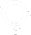
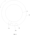
- the limiting structure 20 may have a limiting recess 201 defined in the middle thereof, the lower portion 115 of the first operating portion 11 has a fixture portion 116 defined on an outer peripheral surface thereof, the base 19 has a receiving space 192 defined therein, the lower portion 115 is partially located in the receiving space 192, and the limiting structure 20 is disposed on an inner surface of the receiving space 192.
- the fixture portion 116 is located in the limiting recess 201 (see FIG. 4 ), and thus the first operating portion 11 is restricted from rotating.
- the fixture portion 116 is separated from the limiting recess 201. Therefore, the rotation restriction of the first operating portion 11 is removed, and the first operating portion 11 can be rotated (see FIG. 5 ).
- the limiting structure 20 may be other structures.
- the specific type of the limiting structure 20 can be determined specifically according to different situations. It is only required that the limiting structure 20 can limit the rotation of the first operating portion 11. The specific type of the limiting structure 20 is not limited herein.
- the first operating portion 11 when the second operating portion 12 is located at the first position of the first operating portion 11, the first operating portion 11 is located at the third position of the base 19, so that the second operating portion 12 can rotate relative to the first operating portion 11, and the first operating portion 11 is restricted from rotating.
- the second operating portion 12 is located at the second position of the first operating portion 11, the first operating portion 11 is pressed (the first operating portion 11 can be pressed directly or by pressing the second operating portion 12) to move from the third position to the fourth position, and at this time, the rotation restriction of the first operating portion 11 is removed, and the first operating portion 11 can rotate.
- the operating assembly 10 further includes a second elastic member 21 abutting against the base 19 and the first operating portion 11.
- the first elastic member 16 can automatically drive the first operating portion 11 to move from a position of a pressed state to a position of an initial state (the position at which the first operating portion 11 is not pressed), and the structure is simple and easy to be implemented.
- a lower end of the second elastic member 21 abuts against a bottom surface of the receiving space 192, a lower peripheral edge of the lower portion has a third notch 60 defined therein, and the lower end of the second elastic member 21 abuts against a top surface of the notch 60.
- the second elastic member 21 is a spring, a torsion spring, an elastic sheet, or other elastic members. In the embodiment of the present disclosure, the second elastic member 21 is a spring.
- the operating assembly 10 further includes a switch member 22 configured to output the third electric signal when the first operating portion 11 is pressed.
- the electric signal can be output by pressing the first operating portion 11, the structure is simple, and the cost is low.
- the switch member 22 includes a body 221, and an elastic contact member 222 disposed on the body 221.
- the elastic contact member 222 can move relative to the body 221 under the action of an external force, and the elastic contact member 222 can restore to an initial state when the external force is removed.
- the elastic contact 222 is in the initial state.
- the elastic contact member 222 is pressed by the lower portion 115 of the first operating portion 11 to move relative to the body 221, and the electric signals are output. In this way, the electric signals can be output by pressing the first operating portion 11, the structure is simple, and the cost is low.
- a micro switch may be employed to serve as the switch member 22.
- the body 221 can be connected to the output terminal 19 via a wire, to output a corresponding electric signal.
- the operating assembly 10 further includes an encoder 23.
- the encoder 23 is connected to the first operating portion 11, and the encoder 23 is configured to detect a rotation angle of the first operating portion 11 and output the second electric signal based on the rotation angle.
- the encoder 23 can output different second electric signals based on different rotation angles of the first operating portion 11 to conveniently and quickly control the household appliance 100 to implement different functions, improving the user experience.
- the encoder 23 is mounted on a bottom surface of the lower portion 115. With different rotation angle of the first operating portion 11, the second electric signal of the output is also different, and thus the household appliance 100 can implement different functions based on different second electric signals.
- the embodiments of the present disclosure provide a household appliance 100, which includes the operating assembly 10 according any one of the above embodiments, and a panel 101.
- the operating assembly 10 is mounted on the panel 101.
- the operating assembly 10 when different operations are performed on the first operating portion 11 and the second operating portion 12, the operating assembly 10 can output different electric signals, the functions of the knobs can be multiplied by providing the two operating portions to satisfy the multi-functionalization of the household appliance 100, and the structure is simple and easy to be implementedd the user convenience.
- the base 19 is located at a lower side of the panel 101, the panel 101 has an opening 102 defined thereon, and the first operating portion 11 passes through the opening 102 and is connected to the base 19.
- the base 19 may be fixed inside a housing of the household appliance 100.
- the panel 101 has two operating assemblies 10.
- the number of the operating assembly 10 may be one, three, or more than three.
- the specific number of operation components 10 may be determined according to actual needs, and is not specifically limited herein.
Landscapes
- Rotary Switch, Piano Key Switch, And Lever Switch (AREA)
Claims (9)
- Betriebsanordnung (10) für ein Haushaltsgerät (100), wobei die Betriebsanordnung (10) Folgendes umfasst:einen ersten Betriebsbereich (11);einen zweiten Betriebsbereich (12), wobei der erste Betriebsbereich (11) zumindest teilweise in dem zweiten Betriebsbereich (12) angeordnet ist, undwobei der zweite Betriebsbereich (12) in der Lage ist, sich an einer ersten Position und einer zweiten Position des ersten Betriebsbereichs (11) zu befinden, und in der Lage ist, sich zwischen der ersten Position und der zweiten Position zu bewegen;und eine Kupplungsstruktur (15),wobei die Betriebsanordnung (10) so konfiguriert ist, dass:wenn festgestellt wird, dass sich der zweite Betriebsbereich (12) an der ersten Position befindet, der zweite Betriebsbereich (12) relativ zum ersten Betriebsbereich (11) drehbar ist, um ein erstes elektrisches Signal zu erzeugen;wenn festgestellt wird, dass sich der zweite Betriebsbereich (12) an der zweiten Position befindet, der zweite Betriebsbereich (12) in der Lage ist, wenn er gedreht wird und mittels der Kupplungsstruktur (15), den ersten Betriebsbereich (11) zur Drehung anzutreiben, ein zweites elektrisches Signal während der Drehung des ersten Betriebsbereichs (11) zu erzeugen; undder erste Betriebsbereich (11) in der Lage ist, gedrückt zu werden, um ein drittes elektrisches Signal zu erzeugen,dadurch gekennzeichnet, dassdie Betriebsanordnung (10) ferner ein erstes Kontaktelement (17), das an dem ersten Betriebsbereich (11) montiert ist, und ein zweites Kontaktelement (18),das an dem zweiten Betriebsbereich (12) montiert ist, umfasst, wobei wenn festgestellt wird, dass sich der zweite Betriebsbereich (12) an der ersten Position befindet, das erste Kontaktelement (17) mit dem zweiten Kontaktelement (18) verbunden wird;wenn festgestellt wird, dass sich der zweite Betriebsbereich (12) an der ersten Position befindet und sich dreht, sich das erste Kontaktelement (17) und das zweite Kontaktelement (18) relativ zueinander drehen, um das erste elektrische Signal zu erzeugen;wenn festgestellt wird, dass sich der zweite Betriebsbereich (12) an der zweiten Position befindet, das erste Kontaktelement (17) von dem zweiten Kontaktelement getrennt wird.
- Betriebsanordnung (10) gemäß Anspruch 1, wobei die Kupplungsstruktur (15) Folgendes umfasst:einen Befestigungsblock (151), der sich entweder am ersten Betriebsbereich (11) oder am zweiten Betriebsbereich (12) befindet; undeinen Befestigungssitz (152), der sich an einem anderen von entweder dem ersten Betriebsbereich (11) oder dem zweiten Betriebsbereich (12) befindet.
- Betriebsanordnung (10) gemäß Anspruch 1 oder 2, ferner umfassend ein erstes elastisches Element (16), wobei
wenn festgestellt wird, dass sich der zweite Betriebsbereich (12) an der zweiten Position befindet, das erste elastische Element (16) zwischen dem ersten Betriebsbereich (11) und dem zweiten Betriebsbereich (12) anliegt und den zweiten Betriebsbereich (12) mit einer Kraft versorgt, um sich von der zweiten Position in die erste Position zu bewegen. - Betriebsanordnung (10) gemäß einem der Ansprüche 1 bis 3, ferner umfassend eine Basis (19), wobei der erste Betriebsbereich (11) beweglich mit der Basis (19) verbunden ist, und die Basis (19) mit einem Ausgangsanschluss (191) versehen ist, wobei der Ausgangsanschluss (191) ein elektrisches Signal der Betriebsanordnung (10) an eine Steuerung des Haushaltsgeräts (100) ausgibt.
- Betriebsanordnung (10) gemäß Anspruch 4, ferner umfassend eine Begrenzungsstruktur (20), die an der Basis (19) angeordnet ist, wobei der erste Betriebsbereich (11) in der Lage ist, an einer dritten Position und einer vierten Position der Basis (19) angeordnet zu sein und zwischen der dritten Position und der vierten Position umschaltbar ist;wenn festgestellt wird, dass sich der erste Betriebsbereich (11) an der dritten Position befindet, die Begrenzungsstruktur (20) mit dem ersten Betriebsbereich (11) verbunden wird, um eine Drehung des ersten Betriebsbereichs (11) zu begrenzen; undwenn festgestellt wird, dass sich der erste Betriebsbereich (11) an der vierten Position befindet, die Begrenzungsstruktur (20) von dem ersten Betriebsbereich (11) getrennt wird, um die Begrenzung der Drehung des ersten Betriebsbereichs (11) aufzuheben, so dass sich der erste Betriebsbereich (11) drehen kann.
- Betriebsanordnung (10) gemäß Anspruch 4 oder 5, ferner umfassend ein zweites elastisches Element (21), das an der Basis (19) und dem ersten Betriebsbereich (11) anliegt.
- Betriebsanordnung (10) gemäß einem der Ansprüche 1 bis 6, ferner umfassend ein Schaltelement (22), das das dritte elektrische Signal als Reaktion auf das Drücken des ersten Betriebsbereichs (11) ausgibt.
- Betriebsanordnung (10) gemäß einem der Ansprüche 1 bis 7, ferner umfassend einen mit dem ersten Betriebsbereich (11) verbundenen Encoder (23), wobei der Encoder (23) einen Drehwinkel des ersten Betriebsbereichs (11) erfasst und das zweite elektrische Signal auf der Grundlage des Drehwinkels ausgibt.
- Haushaltsgerät (100), umfassend:eine Betriebsanordnung (10) gemäß einem der Ansprüche 1 bis 8; undeine Platte (101),wobei die Betriebsanordnung (10) auf der Platte (101) montiert ist.
Applications Claiming Priority (2)
| Application Number | Priority Date | Filing Date | Title |
|---|---|---|---|
| CN202010022867.2A CN111192781B (zh) | 2020-01-09 | 2020-01-09 | 操作组件及家用电器 |
| PCT/CN2020/123676 WO2021139320A1 (zh) | 2020-01-09 | 2020-10-26 | 操作组件及家用电器 |
Publications (3)
| Publication Number | Publication Date |
|---|---|
| EP4033509A1 EP4033509A1 (de) | 2022-07-27 |
| EP4033509A4 EP4033509A4 (de) | 2023-01-04 |
| EP4033509B1 true EP4033509B1 (de) | 2024-09-25 |
Family
ID=70710003
Family Applications (1)
| Application Number | Title | Priority Date | Filing Date |
|---|---|---|---|
| EP20912368.6A Active EP4033509B1 (de) | 2020-01-09 | 2020-10-26 | Bedienungsanordnung und haushaltsgerät |
Country Status (4)
| Country | Link |
|---|---|
| US (1) | US12057277B2 (de) |
| EP (1) | EP4033509B1 (de) |
| CN (1) | CN111192781B (de) |
| WO (1) | WO2021139320A1 (de) |
Families Citing this family (5)
| Publication number | Priority date | Publication date | Assignee | Title |
|---|---|---|---|---|
| CN111192781B (zh) * | 2020-01-09 | 2021-05-25 | 佛山市顺德区美的洗涤电器制造有限公司 | 操作组件及家用电器 |
| US12253874B2 (en) * | 2020-01-19 | 2025-03-18 | Foshan Shunde Midea Electrical Heating Appliances Manufacturing Co., Ltd. | Household appliance knob |
| CN111933473B (zh) * | 2020-08-21 | 2024-05-03 | 南京亚派科技股份有限公司 | 一种励磁型双电源触头按压装置 |
| CN116624832A (zh) * | 2022-09-08 | 2023-08-22 | 广州彩熠灯光股份有限公司 | 信号处理装置、方法及灯光控制台 |
| CN115446250B (zh) * | 2022-09-29 | 2025-08-15 | 富美电气有限公司 | 一种基于紧急关闭ctf系统的安全装置 |
Family Cites Families (19)
| Publication number | Priority date | Publication date | Assignee | Title |
|---|---|---|---|---|
| JP3430186B2 (ja) * | 1994-10-07 | 2003-07-28 | アルプス電気株式会社 | 複合操作型スイッチ装置 |
| DE102004010205B3 (de) * | 2004-03-02 | 2005-10-20 | Siemens Ag | Bedienelement, insbesondere zur Steuerung eines medizinischen Systems |
| DE102005045300A1 (de) * | 2005-09-22 | 2006-09-28 | Audi Ag | Bedienvorrichtung und Verfahren zum Steuern einer ersten und einer zweiten bewegbaren Sonnen- und/oder Windschutzvorrichtung an einem Fahrzeug |
| US7479607B2 (en) * | 2006-07-28 | 2009-01-20 | Bose Corporation | Control knob with safety feature |
| DE102008007930A1 (de) * | 2008-02-07 | 2009-08-13 | Ford Global Technologies, LLC, Dearborn | Lichtschalter für Kraftfahrzeuge |
| CN201199055Y (zh) * | 2008-04-07 | 2009-02-25 | 马旭斌 | 一种燃气灶具的旋钮开关 |
| JP5819130B2 (ja) * | 2011-08-05 | 2015-11-18 | アルプス電気株式会社 | 回転型電気部品 |
| KR20130027255A (ko) * | 2011-09-07 | 2013-03-15 | 삼성전자주식회사 | 키 조립체 및 이를 구비한 회전식 입력 장치 |
| KR20140084712A (ko) * | 2012-12-27 | 2014-07-07 | 현대자동차주식회사 | 스위치 장치 |
| CN105655187B (zh) * | 2016-03-24 | 2018-01-26 | 惠州华阳通用电子有限公司 | 一种多功能按钮 |
| CN208608099U (zh) * | 2017-08-24 | 2019-03-15 | 杨晓彤 | 一种灶具及其旋钮开关 |
| US10546709B2 (en) * | 2017-12-21 | 2020-01-28 | Weg Drives And Controls Automação Ltda | External rotary operating mechanism for a circuit breaker |
| KR101986124B1 (ko) * | 2018-03-15 | 2019-06-05 | 주식회사 서연전자 | 자동차의 스위치 장치 |
| CN208836108U (zh) * | 2018-09-06 | 2019-05-07 | 佛山市顺德区美的洗涤电器制造有限公司 | 磁控旋钮组件和电器设备 |
| CN209084831U (zh) * | 2018-11-07 | 2019-07-09 | 桂林航天工业学院 | 一种增量编码式燃气灶控制装置 |
| CN110131755B (zh) * | 2019-04-25 | 2020-07-10 | 杨永生 | 一种基于按压式旋钮的燃气灶控制方法 |
| CN110626294B (zh) * | 2019-10-30 | 2025-05-09 | 广东升威电子制品有限公司 | 一种开关旋钮及车载触摸屏 |
| CN111192781B (zh) * | 2020-01-09 | 2021-05-25 | 佛山市顺德区美的洗涤电器制造有限公司 | 操作组件及家用电器 |
| JP7694909B2 (ja) * | 2021-11-17 | 2025-06-18 | アルプスアルパイン株式会社 | 複合型入力装置 |
-
2020
- 2020-01-09 CN CN202010022867.2A patent/CN111192781B/zh active Active
- 2020-10-26 EP EP20912368.6A patent/EP4033509B1/de active Active
- 2020-10-26 WO PCT/CN2020/123676 patent/WO2021139320A1/zh not_active Ceased
-
2022
- 2022-05-05 US US17/737,960 patent/US12057277B2/en active Active
Also Published As
| Publication number | Publication date |
|---|---|
| CN111192781B (zh) | 2021-05-25 |
| CN111192781A (zh) | 2020-05-22 |
| WO2021139320A1 (zh) | 2021-07-15 |
| EP4033509A4 (de) | 2023-01-04 |
| US20220262583A1 (en) | 2022-08-18 |
| US12057277B2 (en) | 2024-08-06 |
| EP4033509A1 (de) | 2022-07-27 |
Similar Documents
| Publication | Publication Date | Title |
|---|---|---|
| EP4033509B1 (de) | Bedienungsanordnung und haushaltsgerät | |
| US10865875B2 (en) | Dial shift lever device for vehicle | |
| CN111352465B (zh) | 带旋钮功能的按键及其家电控制面板 | |
| US10050622B2 (en) | Operating device and appliance having the device | |
| EP2485111B1 (de) | Verbesserte zurücknehmbare Bedienung für Hausgerät | |
| CN109983279B (zh) | 家用器具用的触觉的操作元件 | |
| CN210897102U (zh) | 一种控制面板组件及家电设备 | |
| US20120152708A1 (en) | Appliance Timer | |
| EP1829071B1 (de) | Haushaltsgerät | |
| CN211555759U (zh) | 一种带旋钮功能的按键及其家电控制面板 | |
| CN111158429A (zh) | 旋钮及家用电器 | |
| CN211669567U (zh) | 旋钮及家用电器 | |
| CN114156114A (zh) | 一种多档多手感旋钮开关 | |
| CN104997391B (zh) | 一种压力调节机构及设有该压力调节机构的压力锅 | |
| CN211827065U (zh) | 一种带旋钮功能的按键及其家电控制面板 | |
| CN216702265U (zh) | 一种可360°旋转调节的控温装置及其电热水壶 | |
| EP1995753A1 (de) | Schaltelement für ein Gerät, insbesondere für ein Haushaltsgerät | |
| CN221960882U (zh) | 一种开关结构 | |
| CN214254217U (zh) | 旋钮操作组件和家用电器 | |
| CN215914214U (zh) | 具有显示功能的旋钮装置和包括该旋钮装置的烹饪电器 | |
| CN213716781U (zh) | 用于厨房电器的控制装置以及包括该控制装置的厨房电器 | |
| CN111211006B (zh) | 按键结构、线控器及空调 | |
| JPH08329785A (ja) | スイッチ装置 | |
| CN212084882U (zh) | 控制面板及料理机 | |
| CN116771941B (zh) | 一种阀体及灶具 |
Legal Events
| Date | Code | Title | Description |
|---|---|---|---|
| STAA | Information on the status of an ep patent application or granted ep patent |
Free format text: STATUS: THE INTERNATIONAL PUBLICATION HAS BEEN MADE |
|
| PUAI | Public reference made under article 153(3) epc to a published international application that has entered the european phase |
Free format text: ORIGINAL CODE: 0009012 |
|
| STAA | Information on the status of an ep patent application or granted ep patent |
Free format text: STATUS: REQUEST FOR EXAMINATION WAS MADE |
|
| 17P | Request for examination filed |
Effective date: 20220422 |
|
| AK | Designated contracting states |
Kind code of ref document: A1 Designated state(s): AL AT BE BG CH CY CZ DE DK EE ES FI FR GB GR HR HU IE IS IT LI LT LU LV MC MK MT NL NO PL PT RO RS SE SI SK SM TR |
|
| A4 | Supplementary search report drawn up and despatched |
Effective date: 20221202 |
|
| RIC1 | Information provided on ipc code assigned before grant |
Ipc: H01H 3/08 20060101ALN20221128BHEP Ipc: H01H 25/06 20060101AFI20221128BHEP |
|
| DAV | Request for validation of the european patent (deleted) | ||
| DAX | Request for extension of the european patent (deleted) | ||
| GRAP | Despatch of communication of intention to grant a patent |
Free format text: ORIGINAL CODE: EPIDOSNIGR1 |
|
| STAA | Information on the status of an ep patent application or granted ep patent |
Free format text: STATUS: GRANT OF PATENT IS INTENDED |
|
| INTG | Intention to grant announced |
Effective date: 20240715 |
|
| RIC1 | Information provided on ipc code assigned before grant |
Ipc: H01H 3/08 20060101ALN20240705BHEP Ipc: H01H 25/06 20060101AFI20240705BHEP |
|
| GRAS | Grant fee paid |
Free format text: ORIGINAL CODE: EPIDOSNIGR3 |
|
| GRAA | (expected) grant |
Free format text: ORIGINAL CODE: 0009210 |
|
| STAA | Information on the status of an ep patent application or granted ep patent |
Free format text: STATUS: THE PATENT HAS BEEN GRANTED |
|
| AK | Designated contracting states |
Kind code of ref document: B1 Designated state(s): AL AT BE BG CH CY CZ DE DK EE ES FI FR GB GR HR HU IE IS IT LI LT LU LV MC MK MT NL NO PL PT RO RS SE SI SK SM TR |
|
| REG | Reference to a national code |
Ref country code: GB Ref legal event code: FG4D |
|
| REG | Reference to a national code |
Ref country code: CH Ref legal event code: EP |
|
| REG | Reference to a national code |
Ref country code: DE Ref legal event code: R096 Ref document number: 602020038515 Country of ref document: DE |
|
| REG | Reference to a national code |
Ref country code: IE Ref legal event code: FG4D |
|
| REG | Reference to a national code |
Ref country code: LT Ref legal event code: MG9D |
|
| PG25 | Lapsed in a contracting state [announced via postgrant information from national office to epo] |
Ref country code: NO Free format text: LAPSE BECAUSE OF FAILURE TO SUBMIT A TRANSLATION OF THE DESCRIPTION OR TO PAY THE FEE WITHIN THE PRESCRIBED TIME-LIMIT Effective date: 20241225 |
|
| PG25 | Lapsed in a contracting state [announced via postgrant information from national office to epo] |
Ref country code: GR Free format text: LAPSE BECAUSE OF FAILURE TO SUBMIT A TRANSLATION OF THE DESCRIPTION OR TO PAY THE FEE WITHIN THE PRESCRIBED TIME-LIMIT Effective date: 20241226 Ref country code: FI Free format text: LAPSE BECAUSE OF FAILURE TO SUBMIT A TRANSLATION OF THE DESCRIPTION OR TO PAY THE FEE WITHIN THE PRESCRIBED TIME-LIMIT Effective date: 20240925 |
|
| PG25 | Lapsed in a contracting state [announced via postgrant information from national office to epo] |
Ref country code: BG Free format text: LAPSE BECAUSE OF FAILURE TO SUBMIT A TRANSLATION OF THE DESCRIPTION OR TO PAY THE FEE WITHIN THE PRESCRIBED TIME-LIMIT Effective date: 20240925 |
|
| PG25 | Lapsed in a contracting state [announced via postgrant information from national office to epo] |
Ref country code: LV Free format text: LAPSE BECAUSE OF FAILURE TO SUBMIT A TRANSLATION OF THE DESCRIPTION OR TO PAY THE FEE WITHIN THE PRESCRIBED TIME-LIMIT Effective date: 20240925 |
|
| PG25 | Lapsed in a contracting state [announced via postgrant information from national office to epo] |
Ref country code: RS Free format text: LAPSE BECAUSE OF FAILURE TO SUBMIT A TRANSLATION OF THE DESCRIPTION OR TO PAY THE FEE WITHIN THE PRESCRIBED TIME-LIMIT Effective date: 20241225 |
|
| REG | Reference to a national code |
Ref country code: NL Ref legal event code: MP Effective date: 20240925 |
|
| PG25 | Lapsed in a contracting state [announced via postgrant information from national office to epo] |
Ref country code: RS Free format text: LAPSE BECAUSE OF FAILURE TO SUBMIT A TRANSLATION OF THE DESCRIPTION OR TO PAY THE FEE WITHIN THE PRESCRIBED TIME-LIMIT Effective date: 20241225 Ref country code: NO Free format text: LAPSE BECAUSE OF FAILURE TO SUBMIT A TRANSLATION OF THE DESCRIPTION OR TO PAY THE FEE WITHIN THE PRESCRIBED TIME-LIMIT Effective date: 20241225 Ref country code: LV Free format text: LAPSE BECAUSE OF FAILURE TO SUBMIT A TRANSLATION OF THE DESCRIPTION OR TO PAY THE FEE WITHIN THE PRESCRIBED TIME-LIMIT Effective date: 20240925 Ref country code: GR Free format text: LAPSE BECAUSE OF FAILURE TO SUBMIT A TRANSLATION OF THE DESCRIPTION OR TO PAY THE FEE WITHIN THE PRESCRIBED TIME-LIMIT Effective date: 20241226 Ref country code: FI Free format text: LAPSE BECAUSE OF FAILURE TO SUBMIT A TRANSLATION OF THE DESCRIPTION OR TO PAY THE FEE WITHIN THE PRESCRIBED TIME-LIMIT Effective date: 20240925 Ref country code: BG Free format text: LAPSE BECAUSE OF FAILURE TO SUBMIT A TRANSLATION OF THE DESCRIPTION OR TO PAY THE FEE WITHIN THE PRESCRIBED TIME-LIMIT Effective date: 20240925 |
|
| REG | Reference to a national code |
Ref country code: AT Ref legal event code: MK05 Ref document number: 1727391 Country of ref document: AT Kind code of ref document: T Effective date: 20240925 |
|
| PG25 | Lapsed in a contracting state [announced via postgrant information from national office to epo] |
Ref country code: NL Free format text: LAPSE BECAUSE OF FAILURE TO SUBMIT A TRANSLATION OF THE DESCRIPTION OR TO PAY THE FEE WITHIN THE PRESCRIBED TIME-LIMIT Effective date: 20240925 |
|
| PG25 | Lapsed in a contracting state [announced via postgrant information from national office to epo] |
Ref country code: IS Free format text: LAPSE BECAUSE OF FAILURE TO SUBMIT A TRANSLATION OF THE DESCRIPTION OR TO PAY THE FEE WITHIN THE PRESCRIBED TIME-LIMIT Effective date: 20250125 Ref country code: PT Free format text: LAPSE BECAUSE OF FAILURE TO SUBMIT A TRANSLATION OF THE DESCRIPTION OR TO PAY THE FEE WITHIN THE PRESCRIBED TIME-LIMIT Effective date: 20250127 |
|
| PG25 | Lapsed in a contracting state [announced via postgrant information from national office to epo] |
Ref country code: SM Free format text: LAPSE BECAUSE OF FAILURE TO SUBMIT A TRANSLATION OF THE DESCRIPTION OR TO PAY THE FEE WITHIN THE PRESCRIBED TIME-LIMIT Effective date: 20240925 Ref country code: RO Free format text: LAPSE BECAUSE OF FAILURE TO SUBMIT A TRANSLATION OF THE DESCRIPTION OR TO PAY THE FEE WITHIN THE PRESCRIBED TIME-LIMIT Effective date: 20240925 |
|
| PG25 | Lapsed in a contracting state [announced via postgrant information from national office to epo] |
Ref country code: ES Free format text: LAPSE BECAUSE OF FAILURE TO SUBMIT A TRANSLATION OF THE DESCRIPTION OR TO PAY THE FEE WITHIN THE PRESCRIBED TIME-LIMIT Effective date: 20240925 |
|
| PG25 | Lapsed in a contracting state [announced via postgrant information from national office to epo] |
Ref country code: EE Free format text: LAPSE BECAUSE OF FAILURE TO SUBMIT A TRANSLATION OF THE DESCRIPTION OR TO PAY THE FEE WITHIN THE PRESCRIBED TIME-LIMIT Effective date: 20240925 Ref country code: AT Free format text: LAPSE BECAUSE OF FAILURE TO SUBMIT A TRANSLATION OF THE DESCRIPTION OR TO PAY THE FEE WITHIN THE PRESCRIBED TIME-LIMIT Effective date: 20240925 |
|
| PG25 | Lapsed in a contracting state [announced via postgrant information from national office to epo] |
Ref country code: PL Free format text: LAPSE BECAUSE OF FAILURE TO SUBMIT A TRANSLATION OF THE DESCRIPTION OR TO PAY THE FEE WITHIN THE PRESCRIBED TIME-LIMIT Effective date: 20240925 Ref country code: CZ Free format text: LAPSE BECAUSE OF FAILURE TO SUBMIT A TRANSLATION OF THE DESCRIPTION OR TO PAY THE FEE WITHIN THE PRESCRIBED TIME-LIMIT Effective date: 20240925 |
|
| PG25 | Lapsed in a contracting state [announced via postgrant information from national office to epo] |
Ref country code: SK Free format text: LAPSE BECAUSE OF FAILURE TO SUBMIT A TRANSLATION OF THE DESCRIPTION OR TO PAY THE FEE WITHIN THE PRESCRIBED TIME-LIMIT Effective date: 20240925 |
|
| REG | Reference to a national code |
Ref country code: CH Ref legal event code: PL |
|
| REG | Reference to a national code |
Ref country code: DE Ref legal event code: R097 Ref document number: 602020038515 Country of ref document: DE |
|
| PG25 | Lapsed in a contracting state [announced via postgrant information from national office to epo] |
Ref country code: MC Free format text: LAPSE BECAUSE OF FAILURE TO SUBMIT A TRANSLATION OF THE DESCRIPTION OR TO PAY THE FEE WITHIN THE PRESCRIBED TIME-LIMIT Effective date: 20240925 |
|
| PG25 | Lapsed in a contracting state [announced via postgrant information from national office to epo] |
Ref country code: DK Free format text: LAPSE BECAUSE OF FAILURE TO SUBMIT A TRANSLATION OF THE DESCRIPTION OR TO PAY THE FEE WITHIN THE PRESCRIBED TIME-LIMIT Effective date: 20240925 |
|
| PG25 | Lapsed in a contracting state [announced via postgrant information from national office to epo] |
Ref country code: BE Free format text: LAPSE BECAUSE OF NON-PAYMENT OF DUE FEES Effective date: 20241031 Ref country code: LU Free format text: LAPSE BECAUSE OF NON-PAYMENT OF DUE FEES Effective date: 20241026 |
|
| PG25 | Lapsed in a contracting state [announced via postgrant information from national office to epo] |
Ref country code: CH Free format text: LAPSE BECAUSE OF NON-PAYMENT OF DUE FEES Effective date: 20241031 |
|
| PLBE | No opposition filed within time limit |
Free format text: ORIGINAL CODE: 0009261 |
|
| STAA | Information on the status of an ep patent application or granted ep patent |
Free format text: STATUS: NO OPPOSITION FILED WITHIN TIME LIMIT |
|
| REG | Reference to a national code |
Ref country code: BE Ref legal event code: MM Effective date: 20241031 |
|
| 26N | No opposition filed |
Effective date: 20250626 |
|
| PG25 | Lapsed in a contracting state [announced via postgrant information from national office to epo] |
Ref country code: SE Free format text: LAPSE BECAUSE OF FAILURE TO SUBMIT A TRANSLATION OF THE DESCRIPTION OR TO PAY THE FEE WITHIN THE PRESCRIBED TIME-LIMIT Effective date: 20240925 |
|
| PG25 | Lapsed in a contracting state [announced via postgrant information from national office to epo] |
Ref country code: IE Free format text: LAPSE BECAUSE OF NON-PAYMENT OF DUE FEES Effective date: 20241026 |
|
| PGFP | Annual fee paid to national office [announced via postgrant information from national office to epo] |
Ref country code: DE Payment date: 20251027 Year of fee payment: 6 |
|
| PGFP | Annual fee paid to national office [announced via postgrant information from national office to epo] |
Ref country code: GB Payment date: 20251024 Year of fee payment: 6 |
|
| PGFP | Annual fee paid to national office [announced via postgrant information from national office to epo] |
Ref country code: IT Payment date: 20251022 Year of fee payment: 6 |
|
| PG25 | Lapsed in a contracting state [announced via postgrant information from national office to epo] |
Ref country code: HR Free format text: LAPSE BECAUSE OF FAILURE TO SUBMIT A TRANSLATION OF THE DESCRIPTION OR TO PAY THE FEE WITHIN THE PRESCRIBED TIME-LIMIT Effective date: 20240925 |
|
| PGFP | Annual fee paid to national office [announced via postgrant information from national office to epo] |
Ref country code: FR Payment date: 20251028 Year of fee payment: 6 |
|
| PG25 | Lapsed in a contracting state [announced via postgrant information from national office to epo] |
Ref country code: CY Free format text: LAPSE BECAUSE OF FAILURE TO SUBMIT A TRANSLATION OF THE DESCRIPTION OR TO PAY THE FEE WITHIN THE PRESCRIBED TIME-LIMIT; INVALID AB INITIO Effective date: 20201026 |
|
| PG25 | Lapsed in a contracting state [announced via postgrant information from national office to epo] |
Ref country code: HU Free format text: LAPSE BECAUSE OF FAILURE TO SUBMIT A TRANSLATION OF THE DESCRIPTION OR TO PAY THE FEE WITHIN THE PRESCRIBED TIME-LIMIT; INVALID AB INITIO Effective date: 20201026 |