EP4033598B1 - Module de batterie, bloc-batterie et appareil utilisant une batterie secondaire - Google Patents
Module de batterie, bloc-batterie et appareil utilisant une batterie secondaire Download PDFInfo
- Publication number
- EP4033598B1 EP4033598B1 EP20929221.8A EP20929221A EP4033598B1 EP 4033598 B1 EP4033598 B1 EP 4033598B1 EP 20929221 A EP20929221 A EP 20929221A EP 4033598 B1 EP4033598 B1 EP 4033598B1
- Authority
- EP
- European Patent Office
- Prior art keywords
- busbar
- battery
- disposed
- along
- battery module
- Prior art date
- Legal status (The legal status is an assumption and is not a legal conclusion. Google has not performed a legal analysis and makes no representation as to the accuracy of the status listed.)
- Active
Links
Images




Classifications
-
- H—ELECTRICITY
- H01—ELECTRIC ELEMENTS
- H01M—PROCESSES OR MEANS, e.g. BATTERIES, FOR THE DIRECT CONVERSION OF CHEMICAL ENERGY INTO ELECTRICAL ENERGY
- H01M50/00—Constructional details or processes of manufacture of the non-active parts of electrochemical cells other than fuel cells, e.g. hybrid cells
- H01M50/20—Mountings; Secondary casings or frames; Racks, modules or packs; Suspension devices; Shock absorbers; Transport or carrying devices; Holders
- H01M50/204—Racks, modules or packs for multiple batteries or multiple cells
- H01M50/207—Racks, modules or packs for multiple batteries or multiple cells characterised by their shape
- H01M50/209—Racks, modules or packs for multiple batteries or multiple cells characterised by their shape adapted for prismatic or rectangular cells
-
- H—ELECTRICITY
- H01—ELECTRIC ELEMENTS
- H01M—PROCESSES OR MEANS, e.g. BATTERIES, FOR THE DIRECT CONVERSION OF CHEMICAL ENERGY INTO ELECTRICAL ENERGY
- H01M50/00—Constructional details or processes of manufacture of the non-active parts of electrochemical cells other than fuel cells, e.g. hybrid cells
- H01M50/50—Current conducting connections for cells or batteries
- H01M50/502—Interconnectors for connecting terminals of adjacent batteries; Interconnectors for connecting cells outside a battery casing
- H01M50/503—Interconnectors for connecting terminals of adjacent batteries; Interconnectors for connecting cells outside a battery casing characterised by the shape of the interconnectors
-
- H—ELECTRICITY
- H01—ELECTRIC ELEMENTS
- H01M—PROCESSES OR MEANS, e.g. BATTERIES, FOR THE DIRECT CONVERSION OF CHEMICAL ENERGY INTO ELECTRICAL ENERGY
- H01M50/00—Constructional details or processes of manufacture of the non-active parts of electrochemical cells other than fuel cells, e.g. hybrid cells
- H01M50/50—Current conducting connections for cells or batteries
- H01M50/572—Means for preventing undesired use or discharge
-
- H—ELECTRICITY
- H01—ELECTRIC ELEMENTS
- H01M—PROCESSES OR MEANS, e.g. BATTERIES, FOR THE DIRECT CONVERSION OF CHEMICAL ENERGY INTO ELECTRICAL ENERGY
- H01M50/00—Constructional details or processes of manufacture of the non-active parts of electrochemical cells other than fuel cells, e.g. hybrid cells
- H01M50/20—Mountings; Secondary casings or frames; Racks, modules or packs; Suspension devices; Shock absorbers; Transport or carrying devices; Holders
- H01M50/233—Mountings; Secondary casings or frames; Racks, modules or packs; Suspension devices; Shock absorbers; Transport or carrying devices; Holders characterised by physical properties of casings or racks, e.g. dimensions
- H01M50/242—Mountings; Secondary casings or frames; Racks, modules or packs; Suspension devices; Shock absorbers; Transport or carrying devices; Holders characterised by physical properties of casings or racks, e.g. dimensions adapted for protecting batteries against vibrations, collision impact or swelling
-
- H—ELECTRICITY
- H01—ELECTRIC ELEMENTS
- H01M—PROCESSES OR MEANS, e.g. BATTERIES, FOR THE DIRECT CONVERSION OF CHEMICAL ENERGY INTO ELECTRICAL ENERGY
- H01M50/00—Constructional details or processes of manufacture of the non-active parts of electrochemical cells other than fuel cells, e.g. hybrid cells
- H01M50/20—Mountings; Secondary casings or frames; Racks, modules or packs; Suspension devices; Shock absorbers; Transport or carrying devices; Holders
- H01M50/249—Mountings; Secondary casings or frames; Racks, modules or packs; Suspension devices; Shock absorbers; Transport or carrying devices; Holders specially adapted for aircraft or vehicles, e.g. cars or trains
-
- H—ELECTRICITY
- H01—ELECTRIC ELEMENTS
- H01M—PROCESSES OR MEANS, e.g. BATTERIES, FOR THE DIRECT CONVERSION OF CHEMICAL ENERGY INTO ELECTRICAL ENERGY
- H01M50/00—Constructional details or processes of manufacture of the non-active parts of electrochemical cells other than fuel cells, e.g. hybrid cells
- H01M50/30—Arrangements for facilitating escape of gases
-
- H—ELECTRICITY
- H01—ELECTRIC ELEMENTS
- H01M—PROCESSES OR MEANS, e.g. BATTERIES, FOR THE DIRECT CONVERSION OF CHEMICAL ENERGY INTO ELECTRICAL ENERGY
- H01M50/00—Constructional details or processes of manufacture of the non-active parts of electrochemical cells other than fuel cells, e.g. hybrid cells
- H01M50/30—Arrangements for facilitating escape of gases
- H01M50/35—Gas exhaust passages comprising elongated, tortuous or labyrinth-shaped exhaust passages
- H01M50/367—Internal gas exhaust passages forming part of the battery cover or case; Double cover vent systems
-
- H—ELECTRICITY
- H01—ELECTRIC ELEMENTS
- H01M—PROCESSES OR MEANS, e.g. BATTERIES, FOR THE DIRECT CONVERSION OF CHEMICAL ENERGY INTO ELECTRICAL ENERGY
- H01M50/00—Constructional details or processes of manufacture of the non-active parts of electrochemical cells other than fuel cells, e.g. hybrid cells
- H01M50/50—Current conducting connections for cells or batteries
- H01M50/502—Interconnectors for connecting terminals of adjacent batteries; Interconnectors for connecting cells outside a battery casing
- H01M50/505—Interconnectors for connecting terminals of adjacent batteries; Interconnectors for connecting cells outside a battery casing comprising a single busbar
-
- H—ELECTRICITY
- H01—ELECTRIC ELEMENTS
- H01M—PROCESSES OR MEANS, e.g. BATTERIES, FOR THE DIRECT CONVERSION OF CHEMICAL ENERGY INTO ELECTRICAL ENERGY
- H01M50/00—Constructional details or processes of manufacture of the non-active parts of electrochemical cells other than fuel cells, e.g. hybrid cells
- H01M50/50—Current conducting connections for cells or batteries
- H01M50/528—Fixed electrical connections, i.e. not intended for disconnection
-
- H—ELECTRICITY
- H01—ELECTRIC ELEMENTS
- H01M—PROCESSES OR MEANS, e.g. BATTERIES, FOR THE DIRECT CONVERSION OF CHEMICAL ENERGY INTO ELECTRICAL ENERGY
- H01M50/00—Constructional details or processes of manufacture of the non-active parts of electrochemical cells other than fuel cells, e.g. hybrid cells
- H01M50/50—Current conducting connections for cells or batteries
- H01M50/543—Terminals
-
- H—ELECTRICITY
- H01—ELECTRIC ELEMENTS
- H01M—PROCESSES OR MEANS, e.g. BATTERIES, FOR THE DIRECT CONVERSION OF CHEMICAL ENERGY INTO ELECTRICAL ENERGY
- H01M50/00—Constructional details or processes of manufacture of the non-active parts of electrochemical cells other than fuel cells, e.g. hybrid cells
- H01M50/50—Current conducting connections for cells or batteries
- H01M50/572—Means for preventing undesired use or discharge
- H01M50/574—Devices or arrangements for the interruption of current
- H01M50/581—Devices or arrangements for the interruption of current in response to temperature
-
- H—ELECTRICITY
- H01—ELECTRIC ELEMENTS
- H01M—PROCESSES OR MEANS, e.g. BATTERIES, FOR THE DIRECT CONVERSION OF CHEMICAL ENERGY INTO ELECTRICAL ENERGY
- H01M2200/00—Safety devices for primary or secondary batteries
- H01M2200/10—Temperature sensitive devices
- H01M2200/103—Fuse
-
- H—ELECTRICITY
- H01—ELECTRIC ELEMENTS
- H01M—PROCESSES OR MEANS, e.g. BATTERIES, FOR THE DIRECT CONVERSION OF CHEMICAL ENERGY INTO ELECTRICAL ENERGY
- H01M2220/00—Batteries for particular applications
- H01M2220/20—Batteries in motive systems, e.g. vehicle, ship, plane
-
- Y—GENERAL TAGGING OF NEW TECHNOLOGICAL DEVELOPMENTS; GENERAL TAGGING OF CROSS-SECTIONAL TECHNOLOGIES SPANNING OVER SEVERAL SECTIONS OF THE IPC; TECHNICAL SUBJECTS COVERED BY FORMER USPC CROSS-REFERENCE ART COLLECTIONS [XRACs] AND DIGESTS
- Y02—TECHNOLOGIES OR APPLICATIONS FOR MITIGATION OR ADAPTATION AGAINST CLIMATE CHANGE
- Y02E—REDUCTION OF GREENHOUSE GAS [GHG] EMISSIONS, RELATED TO ENERGY GENERATION, TRANSMISSION OR DISTRIBUTION
- Y02E60/00—Enabling technologies; Technologies with a potential or indirect contribution to GHG emissions mitigation
- Y02E60/10—Energy storage using batteries
Definitions
- This application relates to the field of batteries, and in particular, to a battery module, a battery pack, and a device using a secondary battery.
- rechargeable batteries have been widely used to provide power for high-power devices such as an electric vehicle.
- a plurality of battery cells are generally connected to electrode terminals by a busbar to form at least one of a serial connection or a parallel connection.
- the battery expands. The expansion causes a tensile force exerted by the busbar on the electrode terminals, thereby affecting reliability of the battery in use.
- the battery module comprises a battery and a confluence component, a plurality of batteries are sequentially arranged in the longitudinal direction, and each battery comprises a first electrode terminal and a second electrode terminal.
- the plurality of batteries includes a first battery and a second battery, and a first electrode terminal of the first battery and a first electrode terminal of the second battery are arranged in a longitudinal direction.
- the plurality of bus members includes a first bus member including a first portion, a second portion, and a third portion. The first portion is connected to a first electrode terminal of the first battery, the second portion is connected to a second electrode terminal of the second battery, and the third portion connects the first portion and the second portion. Through holes are formed in the third part.
- the battery connection piece comprises connection parts (2) and a fusing part (1), wherein the connection parts (2) are arranged at two ends of the battery connection piece, the fusing part (1) is arranged between the two connection parts (2), weaken holes (3) are formed in the fusing part so that the cross area of the fusing part is smaller than the cross areas of the connection parts.
- CN109768206A discloses a power battery pack.
- the power battery pack comprises an even number of cell groups, the even number of cell groups comprise an odd number of first cell groups and a second cell group, the first cell groups and the second cell group are connected in series, the first cell groups are arranged in a positive and negative crossed manner to enable positive electrodes and negative electrodes of each two adjacent first cell groups to face each other, the second cell group is arranged at one side of one first cell group, the positive electrode of the first cell group faces the positive electrode of the second cell group, and the power battery pack also comprises a first overcurrent row connected to the electrodes of the same side and a second overcurrent row connected to the electrodes of the diagonal side.
- WO2019187312A1 discloses a battery module.
- the battery module is provided with: a plurality of battery cells having electrode terminals (2); and bus bars that connect the electrode terminals (2) of the adjacent battery cells to each other in a state where the plurality of battery cells are layered, wherein the bus bars include a first bus bar having a first thickness and a second bus bar having a second thickness larger than the first thickness, and the first bus bar is connected to the electrode terminals (2) of the adjacent battery cells while the second bus bar is not in contact with any of the electrode terminals (2) of the battery cells.
- EP2202825A1 discloses a battery pack, in which external connection terminals are arrayed in the same direction in the module having the plurality of cells connected in series and a wiring that cuts across the module is not generated, and, in which improvement of the workability and reduction of connection failures are achieved by only connecting between the units by means of a bus bar when creating the module.
- Three pieces of flat-plate cells 2a to 2c are arranged in parallel to configure a threepiece unit 1.
- a positive electrode terminal 3 and negative electrode terminal 4 are provided at the top of each of the cells 2a to 2c.
- the negative electrode terminal 4 of the first cell 2a and the positive electrode terminal 3 of the second cell 2b are connected with each other by a first bus bar 5 disposed in an oblique direction, and the negative electrode terminal 4 of the second cell 2b and the positive electrode terminal of the third cell 2c are connected with each other by a second bus bar 6 disposed in a direction perpendicular to the longitudinal direction of the cells.
- Two pieces of flat-plate cells 12a, 12b are arranged in parallel to configure a two-piece unit 11.
- the positive electrode terminals 13 and the negative electrode terminals 14 of the cells 12a, 12b are connected with each other by a second bus bar 16.
- Cooling part 91. Cooling plate; 92. Inlet pipe; 93. Outlet pipe; 10. Constraint part; 101. Position limiting portion; 102. Mounting portion; and 103. Reinforcing rib.
- a plurality of means two or more; the terms such as “upper”, “lower”, “left”, “right”, “inner”, and “outer” indicating a direction or a position relationship are merely intended for ease or brevity of description of this application, but do not indicate or imply that the device or component referred to must be located in the specified direction or constructed or operated in the specified direction. Therefore, such terms shall not be understood as a limitation on this application.
- the terms “first”, “second”, and “third” are merely intended for descriptive purposes, but are not intended to indicate or imply relative importance.
- Perfect is not exactly perpendicular, but within an error tolerance range.
- Parallel is not exactly parallel, but within an error tolerance range.
- connection may be a fixed connection, a detachable connection, or an integrated connection, and may be a direct connection or an indirect connection implemented through an intermediary.
- this application provides a device using a secondary battery.
- the battery includes a battery module 2 or a battery pack.
- the battery pack may include a box assembly 1 and a battery module 2.
- One or more battery modules 2 are disposed in the box assembly 1.
- Devices using a secondary battery include a vehicle, a ship, an energy storage cabinet, an unmanned aerial vehicle, and the like. This application aims to improve the working performance of the device by improving the working reliability and safety of the battery module 2 or the battery pack.
- the battery pack includes a box assembly 1, a constraint part 10, an upper cover 13, and a plurality of battery cells 20.
- the box assembly 1 includes a box 11 and a beam 12.
- the box 11 contains an opening end.
- the beam 12 is fixed in the box 11.
- One or more beams 12 may be disposed to partition an internal space of the box 11 into a plurality of accommodation cavities Q.
- the battery cells 20 may be divided into a plurality of groups. Each group of battery cells 20 is disposed in a different accommodation cavity Q.
- a constraint part 10 is disposed corresponding to each group of battery cells 20.
- the constraint part 10 overlays the group of battery cells 20 and is fixed to the beam 12 and is configured to provide a steady pressing force to the battery cells 20, so as to restrict the battery cells 20 from expanding and increase the service life of the battery pack.
- the constraint part 10 includes a position limiting portion 101 and two mounting portions 102.
- the position limiting portion 101 overlays the battery cells 20 in a corresponding group.
- the two mounting portions 102 are connected to two sides of the position limiting portion 101 along a grouping direction of the battery cells 20 respectively, and are fixed to the beams 12 at two sides of the battery cells 20 in the corresponding group along the grouping direction respectively.
- the position limiting portion 101 as a whole protrudes against the two mounting portions 102 away from the battery cells 20.
- An expansion force received by the constraint part 10 is very large when the entire module expands. Therefore, the constraint part 10 herein is fixed by riveting and gluing.
- This fixing method can greatly improve the connection strength of a pressure plate, and can reduce the number of fasteners and reduce costs in contrast to a practice of fixing by using a rivet nut followed by a screw.
- a fixing method other than the riveting and gluing method may be applied, that is, the two mounting portions 102 of the constraint part 10 are directly welded to the beam 12 by means of laser welding as long as the strength permits, thereby implementing the fixing method without a fastener.
- the constraint part 10 may be formed by bending a flat plate.
- a reinforcing rib 103 may be disposed on the position limiting portion 101.
- the reinforcing rib 103 is disposed on an outer surface of the position limiting portion 101 and may be formed by stamping.
- the structural strength of the constraint part 10 can be increased by disposing the reinforcing rib 103, thereby reducing weight and increasing rigidity and deflection of the entire constraint part 10.
- the upper cover 13 is disposed at a side that is of the constraint part 10 and that is away from the box 11, and is snap-fitted to the opening end of the box 11 along a height direction of the battery pack to close off the opening end of the box 11.
- "Close off” here means a hermetic connection between the upper cover 13 and the box 11, and can prevent external liquid and moisture from entering the battery pack, and improve the safety performance of the battery pack.
- the box 11 and the upper cover 13 may be connected by a bolt or by other detachable connection means.
- the battery cells 20 in the battery pack can form a battery module 2 as a modular structure.
- the battery module 2 may be disposed in the battery pack or used independently.
- the battery module 2 includes a battery cell assembly 2A and a first busbar 3.
- the battery cell assembly 2A includes at least two battery cells 20 arranged along a third direction z.
- Each of the battery cells 20 includes two electrode terminals 242: a positive electrode terminal and a negative electrode terminal.
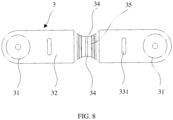
- the first busbar 3 includes a main portion 32 and two connecting portions 31. An extension direction of the first busbar 3 tilts against the third direction z at a preset angle.
- the first busbar 3 and a second busbar 4 to be mentioned later may also be referred to as electrical connecting plates, aluminum bars, busbars, or the like.
- the first busbar 3 may be formed in a strip-shaped sheet structure.
- the two connecting portions 31 are connected to the electrode terminals 242 of the two battery cells 20 in the same battery cell assembly 2A respectively. As shown in FIG. 4 , in the same battery cell assembly 2A, the largest lateral surfaces of two adjacent battery cells 20 are disposed opposite to each other.
- the first busbar 3 is connected to the staggered electrode terminals 242 on the two battery cells 20.
- the main portion 32 is located between the two connecting portions 31.
- a deformation inducing portion is disposed on the main portion 32.
- the deformation inducing portion is configured to reduce at least a force required for deforming the main portion 32 along a first direction x.
- the first direction x is parallel to a lateral surface of the battery cell 20 and perpendicular to the third direction z, where the lateral surface is a surface on which the electrode terminals 242 are disposed.
- the first busbar 3 tilts against the third direction z at a preset angle.
- the generated expansion force is exerted on the first busbar 3 through the electrode terminal 242. Consequently, the first busbar 3 receives an external force along the length direction and an external force along the width direction concurrently.
- the busbar is generally disposed parallel to the third direction z.
- the design of the busbar can reduce merely the force required to deform the busbar along the length direction. If such busbar tilts when connecting to the battery cell 20, a considerable force is still received in the width direction of the busbar when the battery cell 20 expands.
- a deformation inducing portion is disposed on the main portion 32.
- the first busbar 3 is easily deformable in the first direction x to absorb the external force, thereby reducing the tensile force exerted on the electrode terminals 242 and ensuring high reliability of the connection between the electrode terminals 242 and the electrode assembly.
- the size of the battery cell 20 along the third direction z is smaller than the size along the first direction x. Therefore, when the battery cell 20 expands along the third direction z, the first busbar 3 receives the external force along the first direction x and the external force along the third direction z concurrently, where the external force along the first direction x is greater than the external force along the third direction z. With the deformation inducing portion disposed, the first busbar 3 is easily deformable in the first direction x to absorb a majority of the external force, thereby significantly reducing the tensile force exerted on the electrode terminals 242 and ensuring high reliability of the connection between the electrode terminals 242 and the electrode assembly.
- the battery cell 20 further includes a first explosion-proof valve 243.
- the first explosion-proof valve 243 is disposed between the two electrode terminals 242.
- the first busbar 3 is connected to the two staggered electrode terminals 242 on the two battery cells 20. Therefore, by this connection method, the first busbar 3 is closer to the first explosion-proof valves 243 of the two battery cells 20 connected to the first busbar. At the first explosion-proof valves, heat is concentrated.
- the first busbar 3 breaks off more easily in a case of thermal runaway, so as to break a high-voltage circuit of the entire battery module 2, raise a thermal runaway alarm and take protection measures in time, and improve safety of the battery in operation.
- the deformation inducing portion is symmetric with respect to a lengthwise middle position of the main portion (32), so that the first busbar 3 receives a force evenly and brings the same acting effect on the two battery cells 20.
- the middle position is a thermal stress concentration point of a thermal field due to the deformation inducing portion disposed, and can fuse off the first busbar 3 quickly to break the high-voltage circuit of the entire module, thereby allowing enough time to raise a thermal runaway alarm and take protection measures.
- the deformation inducing portion in this embodiment of this application may be in various forms of structure.
- at least one of a groove, a through-groove, a gap 33, a blind hole, or a via hole is disposed on a lateral surface that is of the main portion 32 and that is perpendicular to the thickness direction; or, a recess 34 is disposed on a lateral surface that is of the main portion 32 and that is perpendicular to the width direction.
- All variations fall within the protection scope of this application as long as the first busbar 3 is formed of an appropriate material and contains a deformation inducing portion that can reduce the rigidity of the main portion 32 along the first direction (x).
- the deformation inducing portion includes a gap 33.
- the gap 33 runs through along the thickness direction of the main portion 32.
- a cross-sectional area of the first busbar 3 at a position where the deformation inducing portion is disposed is configured to satisfy the current-carrying capacity of the first busbar 3.
- the cross-sectional area of the first busbar 3 along the width direction is reduced, so as to reduce the rigidity along the width direction.
- the width direction of the first busbar 3 tilts against the third direction z. Therefore, the force required for deforming the main portion 32 along the first direction x and the third direction z can be reduced concurrently, thereby reducing the tensile force on the electrode terminals 242.
- a fragile portion where the gap 33 is located can fuse off more easily to break the circuit.
- the gap 33 includes two transverse grooves 331.
- the two transverse grooves 331 extend along the width direction of the first busbar 3 and are spaced apart along the length direction of the first busbar 3.
- the two transverse grooves 331 may be disposed in a middle region of the main portion 32 along the width direction.
- the transverse grooves 331 extending along the width direction of the first busbar 3 can effectively reduce the cross-sectional area of the first busbar 3 along the width direction in a local region, so as to reduce the rigidity along the width direction. In this way, the force required for deforming the main portion 32 along the first direction x and the third direction z can be reduced effectively, thereby reducing the tensile force on the electrode terminals 242.
- the two transverse grooves 331 are disposed at positions close to the two electrode terminals 242 on the main portion 32 along the length direction. In this way, when any electrode terminal 242 exerts an external force on the connected first busbar 3, the first busbar 3 is easily deformable effectively to reduce the tensile force on the electrode terminal 242.
- the gap 33 further includes a longitudinal groove 332.
- the longitudinal groove 332 extends along the length direction of the first busbar 3, and two ends of the longitudinal groove 332 communicate with the two transverse grooves 331 respectively. Both the longitudinal groove 332 and the two transverse grooves 331 may be disposed in a middle region of the main portion 32 along the width direction.
- the longitudinal groove 332 extending along the length direction of the first busbar 3 is added, so as to evenly reduce the cross-sectional area of the first busbar 3 along the width direction within a section of a preset length of the main portion 32, and reduce the rigidity in the section of such length of the main portion along the width direction.
- the first busbar 3 can evenly deform as a whole when subjected to an external force, so as to reduce the tensile force on the electrode terminals 242, and prevent the first busbar 3 from affecting the service life due to large local deformation.
- the longitudinal groove 332 can also reduce the impact on the current-carrying capacity of the first busbar 3.
- the length of the longitudinal groove 332 may be increased as much as practicable.
- the width of the longitudinal groove 332 is relatively large, the current-carrying capacity of the first busbar 3 will be affected.
- the rigidity of the first busbar 3 is further reduced on the basis of ensuring the current-carrying capacity of the first busbar 3, thereby minimizing the tensile force exerted on the electrode terminals 242 and making it easier to break off the first busbar in a case of thermal runaway.
- the gap 33 further includes two longitudinal grooves 332.
- the two longitudinal grooves 332 extend along the length direction of the first busbar 3 and are spaced apart. One end of each longitudinal groove 332 communicates with a corresponding transverse groove 331.
- the two longitudinal grooves 332 extend opposite to each other.
- the longitudinal groove 332 and each transverse groove 331 that communicate with each other form a T-shaped groove.
- the two T-shaped grooves are disposed symmetrically with respect to a lengthwise middle position of the main portion 32, and are both located in a widthwise middle region of the main portion 32.
- Such a structure can improve the connection reliability of the electrode terminals 242 while reducing the rigidity of the first busbar 3.
- the deformation inducing portion includes a recess 34.
- the recess 34 is disposed at a side of the main portion 32 along the width direction, and is configured to reduce the width of the first busbar 3.
- a sidewall of the recess 34 may be arc-shaped, hyperbola-shaped, parabolashaped, or the like to mitigate stress concentration, or may be polygonal.
- the effect of the gap 33 is strengthened, the rigidity of the first busbar 3 along the width direction can be further reduced, and the force required for deforming the main portion 32 along the first direction x and the third direction z can be further reduced. Therefore, the tensile force on the electrode terminals 242 is reduced, and the reliability of the connection between the first busbar 3 and each electrode terminal 242 is improved. In addition, in a case of thermal runaway, the first busbar can break off more easily to break the circuit, thereby improving the reliability and safety of the battery module 2 in operation.
- the recess 34 may be disposed at a middle position of the main portion 32 along the length direction.
- the recess 34 is disposed at both sides of the main portion 32 along the width direction.
- the first busbar 3 is structurally symmetric with respect to a midline between the two widthwise sides and thereby receives the force evenly. Moreover, the rigidity at the middle position along the length direction can be reduced. When either of the electrode terminals 242 exerts an external force on the first busbar 3, deformation occurs more easily. In addition, the middle position is relatively close to the first explosion-proof valves 243 of both battery cells 20 connected to the first busbar, so that the first busbar 3 can fuse off more easily in a case of thermal runaway.
- the deformation inducing portion includes a bend portion 35.
- the bend portion 35 protrudes against the connecting portion 31 toward at least one side in the thickness direction of the first busbar 3. That is, the bend portion 35 arches outward against the main portion 32.
- the bend portion 35 may be arc-shaped, U-shaped, rectangular, trapezoidal, or the like
- the bend portion 35 when the battery cell 20 expands and exerts an external force on the first busbar 3 along the length direction through the electrode terminals 242, the bend portion 35 protrudes to form an elastic structure, so as to be easily stretched to absorb the external force received by the first busbar 3 along the length direction when the battery cell 20 expands, and reduce the tensile force on the electrode terminals 242. Moreover, the bend portion 35 increases a surface area of the main portion 32 to absorb more heat more easily. Because the recess portion 34 reduces the width of the bend portion 35, the first busbar 3 can break off easily at the recess when the battery cell 20 is thermally runaway, thereby improving the safety of the battery module 2 in operation.
- the bend portion 35 as a whole protrudes against the connecting portion 31 away from the battery cell 20.
- This structure enables the first busbar 3 to be disposed closer to the battery cell 20, so that the connection between the first busbar 3 and each electrode terminal 242 is stable and reliable.
- the space at a side that is of the first busbar 3 and that is away from the battery cell 20 is sufficient for disposing the bend portion 35 to meet the need of deformation.
- the bend portion 35 is located at the middle position of the main portion 32 along the length direction.
- the bend portion 35 disposed can concurrently absorb the external force exerted by the two electrode terminals 242 on the first busbar 3 along the length direction.
- the deformation inducing portion includes a gap 33, a recess 34, and a bend portion 35.
- the bend portion 35 is located at the middle position of the main portion 32 along the length direction.
- the gap 33 is disposed symmetrically along the length direction of the first busbar 3 with respect to the bend portion 35.
- the two transverse grooves 331 of the gap 33 are located at two sides of the bend portion 35 respectively, and the two ends of the longitudinal groove 332 pass through the bend portion 35 along the length direction and communicate with the two transverse grooves 331 respectively.
- At least a part of the recess 34 is disposed at a side of the bend portion 35 along the width direction of the first busbar 3 and is configured to reduce the width of the first busbar 3.
- the first busbar 3 when the battery cell 20 expands along the third direction z, the first busbar 3 receives an external force along the first direction x and the third direction z. Through combined action of the gap 33, the recess 34, and the bend portion 35, the first busbar 3 is allowed to deform to effectively absorb the external force received in the first direction x and the third direction z, thereby minimizing the force on the electrode terminals 242 and improving the reliability of the battery module 2 in operation.
- the battery cell 20 further includes a first explosion-proof valve 243.
- the first explosion-proof valves 243 of the two battery cells 20 connected to the first busbar 3 are located at two sides of the first busbar 3 in the width direction respectively.
- the first busbar 3 at least partly overlays the first explosion-proof valve 243 of the battery cell 20 connected to the first busbar.
- first explosion-proof valve 243 When either the upper battery cell 20 or the lower battery cell connected to the first busbar 3 is thermally runaway, heat, sparks, and dust in the battery cell 20 will be ejected through the first explosion-proof valve 243 and directly act on the first busbar 3, thereby making it easier to fuse off the first busbar 3.
- the battery module 2 further includes a second busbar 4 and a plurality of battery cell assemblies 2A arranged along the first direction x. Two adjacent battery cell assemblies 2A are electrically connected by the second busbar 4.
- the second busbar 4 extends along the first direction x.
- each first busbar 3 and each second busbar 4 are alternately arranged along the first direction x.
- the battery cells 20 are serially connected. Two adjacent first busbars 3 tilt in opposite directions.
- the second busbar 4 may adopt a structure similar to that of the first busbar 3, or may omit the deformation inducing portion.
- the battery module 2 further includes two output electrodes 5 configured to output a positive electrode and a negative electrode of the battery module 2 formed by connecting the battery cells 20.
- a battery pack may include at least one battery module 2.
- the battery modules 2 may be arranged alongside or spaced apart along the second direction y.
- two battery modules 2 may be disposed between two adjacent beams 12.
- the largest lateral surfaces of the battery cells 20 may be approximately parallel to the bottom surface of the box 11.
- This placement method is also known as flat placement.
- the height of the battery cell 20 in the third direction z is relatively small. Therefore, the flat placement method reduces the overall height of the battery module 2, and is more suitable for a device in which the battery installation space is relatively short.
- a box assembly 1 includes a box 11 and a beam 12.
- the beam 12 is fixed in the box 11, and partitions an internal space of the box 11 into a plurality of accommodation cavities Q.
- At least one battery module 2 is disposed in each accommodation cavity Q.
- the battery pack further includes a connecting piece 6 configured to connect the output electrodes 5 in each battery module 2 to implement serial connection or parallel connection of the battery modules 2, so as to achieve electrical performance required by the battery pack.
- a first mounting hole 111 may be disposed on the box 11, and is configured to mount an electrical connector 7.
- the electrode terminals 242 of each battery cell 20 in each battery module 2 are disposed toward the beam 12, and a preset interval L exists between the battery cell 20 and a lateral surface on which the electrode terminals 242 are disposed, and a sidewall of the beam 12, to form an exhaust duct B.
- the heat, sparks, and dust ejected through the first explosion-proof valve 243 may fuse off the first busbar 3.
- An airflow flows toward two sides along the exhaust dust B, and flows to the second explosion-proof valve 8 through the gap between the end of the beam 12 and the inner wall of the box 11, and is finally expelled outward through the second explosion-proof valve 8 to reduce the temperature in the box 11 and improve battery safety.
- At least one second mounting hole 112 is disposed on the box 11.
- the second explosion-proof valve 8 is mounted on the box 11 through the second mounting hole 112.
- the battery pack further includes a cooling part 9.
- the cooling part 9 includes a cooling plate 91, in which a cooling cavity is disposed. Both an inlet pipe 92 and an outlet pipe 93 communicate with the cooling cavity of the cooling plate 91.
- two adjacent battery modules 2 may be mounted with the electrode terminals 242 being away from each other, thereby saving installation space.
- the cooling plate 91 may be disposed between two adjacent battery modules 2 so that the two adjacent battery modules 2 are cooled concurrently by one cooling plate 91.
- the two adjacent battery modules 2 may be mounted with the electrode terminals 242 facing each other. A safe distance needs to be reserved between the electrode terminals 242 of the adjacent battery modules 2.
- a cooling plate 91 may be respectively disposed at lateral surfaces that are of the two battery modules 2 and that are away from the electrode terminals 242.
- the method of connection between the first busbar 3 and the second busbar 4 and the battery cell 20 as well as the structural forms, which are described in this application, are applicable not only to a structure in which the battery cells 20 are placed flatly, but also to the battery module 2 in which the battery cells 20 are arranged vertically.
- each battery cell 20 includes a housing 21 and an electrode assembly 22 disposed in the housing 21.
- the housing 21 may be in a hexahedral shape or other shapes, and contains an opening.
- the electrode assembly 22 is accommodated in the housing 21.
- the opening of the housing 21 is covered with a cap assembly 24.
- the cap assembly 24 includes a cap 241 and two electrode terminals 242 disposed on the cap 241.
- the two electrode terminals 242 are a first electrode terminal and a second electrode terminal.
- the first electrode terminal may be a positive electrode terminal, and the second electrode terminal may be a negative electrode terminal. In other embodiments, the first electrode terminal may be a negative electrode terminal, and the second electrode terminal may be a positive electrode terminal.
- An adapter strip 23 is disposed between the cap assembly 24 and the electrode assembly 22. Tabs of the electrode assembly 22 are electrically connected to the electrode terminals on the cap 241 through the adapter strip 23.
- a first explosion-proof valve 243 is disposed between the two electrode terminals 242 on the cap 241.
- two electrode assemblies 22 are disposed in the housing 21.
- the two electrode assemblies 22 are stacked along a height direction (Z direction) of the battery cells 20.
- the height direction of the battery cells 20 is identical to the height direction of the battery pack. Nevertheless, in other embodiments, one electrode assembly 22 may be disposed in the housing 21, or at least three electrode assemblies 22 are disposed in the housing 21.
- a plurality of electrode assemblies 22 are stacked in the height direction (z direction) of the battery cells 20.
- the electrode assembly 22 includes a first electrode plate 221, a second electrode plate 222, and a separator 223 disposed between the first electrode plate 221 and the second electrode plate 222.
- the first electrode plate 221 may be a positive electrode plate and the second electrode plate 222 may be a negative electrode plate. In other embodiments, the first electrode plate 221 may be a negative electrode plate, and the second electrode plate 222 may be a positive electrode plate.
- the separator 223 is an insulator between the first electrode plate 221 and the second electrode plate 222.
- An active material of the positive electrode plate may be coated onto a coated region of the positive electrode plate, and an active material of the negative electrode plate may be coated onto a coated region of the negative electrode plate.
- a part extending from the coated region of the positive electrode plate serves as a positive tab, and a part extending from the coated region of the negative electrode plate serves as a negative tab.
- the positive tab is connected to the positive electrode terminal on the cap assembly 24 through the positive adapter strip.
- the negative tab is connected to the negative electrode terminal on the cap assembly 24 through the negative adapter strip.
- the electrode assembly 22 is jell-roll structure.
- the first electrode plate 221, the separator 223, and the second electrode plate 222 are all strapshaped structures.
- the first electrode plate 221, the separator 223, and the second electrode plate 222 are sequentially stacked and wound for at least two circles to form an electrode assembly 22.
- the electrode assembly 22 is flat.
- the electrode assembly 22 may be wound into a flat shape directly, or wound into a hollow cylindrical structure first and then calendered into a flat shape.
- FIG. 10 is a schematic outline of the electrode assembly 22.
- Outer surfaces of the electrode assembly 22 include two flattened faces 224.
- the two flattened faces 224 are disposed opposite to each other along the height direction (z direction) of the battery cells 20.
- the electrode assembly 22 is an approximately hexahedral structure.
- the flattened faces 224 are approximately parallel to a winding axis and are outer surfaces that are largest in area.
- the flattened faces 224 may be surfaces that are relatively flat, but not necessarily exactly planar.
- the electrode assembly 22 is a stacked structure.
- the electrode assembly 22 contains a plurality of first electrode plates 221 and a plurality of second electrode plates 222.
- a separator 223 is disposed between a first electrode plate 221 and a second electrode plate 222.
- the first electrode plate 221 and the second electrode plate 222 are stacked along the height direction (z direction) of the battery cells 20.
- the electrode assembly 22 In a charge or discharge process, the electrode assembly 22 inevitably expands along the thickness direction of the electrode plate. The expansion amounts of all electrode plates are accumulated. The expansion amount accumulated in the height direction is larger than the expansion amount accumulated in other directions, so that an external force is exerted on the first busbar 3 through the electrode terminal 242.
Landscapes
- Chemical & Material Sciences (AREA)
- Chemical Kinetics & Catalysis (AREA)
- Electrochemistry (AREA)
- General Chemical & Material Sciences (AREA)
- Engineering & Computer Science (AREA)
- Aviation & Aerospace Engineering (AREA)
- Battery Mounting, Suspending (AREA)
- Connection Of Batteries Or Terminals (AREA)
- Gas Exhaust Devices For Batteries (AREA)
Claims (13)
- Module de batterie (2), comprenant :un ensemble d'éléments de batterie (2A), comprenant au moins deux éléments de batterie (20) disposés dans une troisième direction (z), dans lequel chacun des éléments de batterie (20) comprend des bornes d'électrode (242) ; etune première barre omnibus (3), comprenant une partie principale (32) et deux parties de connexion (31), dans lequel la première barre omnibus (3) est placée à un angle par rapport à la troisième direction (z), les deux parties de connexion (31) sont connectées aux bornes d'électrode (242) des deux éléments de batterie (20) dans un ensemble d'éléments de batterie identique (2A), respectivement, la partie principale (32) est connectée entre les deux parties de connexion (31), une partie facilitant la déformation est disposée sur la partie principale (32), et la partie facilitant la déformation est conçue pour réduire au moins une force nécessaire pour déformer la partie principale (32) dans une première direction (x), et la première direction (x) est parallèle à une surface latérale de l'élément de batterie (20) et perpendiculaire à la troisième direction (z), dans lequel la surface latérale est une surface sur laquelle les bornes d'électrode (242) sont disposées ;dans lequel la partie facilitant la déformation comprend un écartement (33), et l'écartement (33) traverse la partie principale (32) dans le sens de l'épaisseur, l'écartement (33) comprend deux rainures transversales (331), et les deux rainures transversales (331) s'étendent dans le sens de la largeur de la première barre omnibus (3) et sont espacées dans le sens de la longueur de la première barre omnibus (3).
- Module de batterie (2) selon la revendication 1, dans lequel l'écartement (33) comprend en outre une rainure longitudinale (332), la rainure longitudinale (332) s'étend dans le sens de la longueur de la première barre omnibus (3), et deux extrémités de la rainure longitudinale (332) communiquent avec les deux rainures transversales (331), respectivement ; ou
l'écartement (33) comprend en outre deux rainures longitudinales (332), les deux rainures longitudinales (332) s'étendent dans le sens de la longueur de la première barre omnibus (3) et sont espacées, et une extrémité de chaque rainure longitudinale (332) communique avec une rainure transversale correspondante (331) . - Module de batterie (2) selon la revendication 1 ou 2, dans lequel la partie facilitant la déformation comprend un évidement (34), et l'évidement (34) est disposé sur le côté de la largeur de la partie principale (32) et est conçu pour réduire une largeur de la partie principale (32) .
- Module de batterie (2) selon la revendication 3, dans lequel l'évidement (34) est disposé sur les deux côtés de la largeur de la partie principale (32).
- Module de batterie (2) selon l'une quelconque des revendications 1 à 4, dans lequel la partie facilitant la déformation comprend une partie fléchie (35), et la partie fléchie (35) fait saillie contre la partie de connexion (31) dans le sens de l'épaisseur de la première barre omnibus (3).
- Module de batterie (2) selon la revendication 5, dans lequel la partie fléchie (35) fait saillie contre la partie de connexion (31) à distance de l'élément de batterie (20) .
- Module de batterie (2) selon la revendication 5 ou 6, dans lequel la partie fléchie (35) est située à une position au milieu de la longueur de la partie principale (32) ;la partie facilitant la déformation comprend en outre un écartement (33), et l'écartement (33) est disposé de façon symétrique dans le sens de la longueur de la première barre omnibus (3) par rapport à la partie fléchie (35) ; et/oula partie facilitant la déformation comprend en outre un évidement (34), et au moins une partie de l'évidement (34) est disposée sur un côté de la partie fléchie (35) dans le sens de la largeur de la première barre omnibus (3), et est conçue pour réduire une largeur de la première barre omnibus (3).
- Module de batterie (2) selon l'une quelconque des revendications 1 à 7, dans lequel l'élément de batterie (20) comprend en outre une première soupape antidéflagrante (243), et les premières soupapes antidéflagrantes (243) des deux éléments de batterie (20) connectés à la première barre omnibus (3) sont situées sur deux côtés de la largeur de la première barre omnibus (3), respectivement.
- Module de batterie (2) selon l'une quelconque des revendications 1 à 7, dans lequel l'élément de batterie (20) comprend une première soupape antidéflagrante (243), et la première barre omnibus (3) recouvre au moins en partie la première soupape antidéflagrante (243) de l'élément de batterie (20) connecté à la première barre omnibus.
- Module de batterie (2) selon l'une quelconque des revendications 1 à 9, comprenant en outre une seconde barre omnibus (4) et une pluralité d'ensembles d'éléments de batterie (2A) disposés dans la première direction (x), deux ensembles d'éléments de batterie (2A) adjacents sont connectés électriquement par la seconde barre omnibus (4), et la seconde barre omnibus (4) s'étend dans la première direction (x).
- Bloc-batterie, comprenant :un ensemble boîtier (1) ; etle module de batterie (2) selon l'une quelconque des revendications 1 à 10, disposé dans l'ensemble boîtier (1) .
- Bloc-batterie selon la revendication 11, dans lequel l'ensemble boîtier (1) comprend un boîtier (11) et une traverse (12), et la traverse (12) est disposée à l'intérieur du boîtier (11) et sépare le boîtier (11) en une pluralité de cavités de réception (Q) ; et
au moins un module de batterie (2) est disposé dans chaque cavité de réception (Q), les bornes d'électrode (242) de chaque élément de batterie (20) dans chaque module de batterie (2) sont orientées vers la traverse (12), et un intervalle prédéfini (L) existe entre l'élément de batterie (20) et une paroi latérale de la traverse (12) pour former un conduit d'échappement (B). - Dispositif utilisant une batterie secondaire, comprenant :le module de batterie (2) selon l'une quelconque des revendications 1 à 10 ; et/oule bloc-batterie selon la revendication 11 ou 12.
Applications Claiming Priority (2)
| Application Number | Priority Date | Filing Date | Title |
|---|---|---|---|
| CN202010259301.1A CN112310575B (zh) | 2020-04-03 | 2020-04-03 | 电池模块、电池组及使用二次电池的装置 |
| PCT/CN2020/141800 WO2021196796A1 (fr) | 2020-04-03 | 2020-12-30 | Module de batterie, bloc-batterie et appareil utilisant une batterie secondaire |
Publications (4)
| Publication Number | Publication Date |
|---|---|
| EP4033598A1 EP4033598A1 (fr) | 2022-07-27 |
| EP4033598A4 EP4033598A4 (fr) | 2023-01-18 |
| EP4033598B1 true EP4033598B1 (fr) | 2024-01-31 |
| EP4033598C0 EP4033598C0 (fr) | 2024-01-31 |
Family
ID=74336753
Family Applications (1)
| Application Number | Title | Priority Date | Filing Date |
|---|---|---|---|
| EP20929221.8A Active EP4033598B1 (fr) | 2020-04-03 | 2020-12-30 | Module de batterie, bloc-batterie et appareil utilisant une batterie secondaire |
Country Status (6)
| Country | Link |
|---|---|
| US (1) | US12334591B2 (fr) |
| EP (1) | EP4033598B1 (fr) |
| JP (2) | JP7618672B2 (fr) |
| KR (1) | KR102874831B1 (fr) |
| CN (1) | CN112310575B (fr) |
| WO (1) | WO2021196796A1 (fr) |
Families Citing this family (30)
| Publication number | Priority date | Publication date | Assignee | Title |
|---|---|---|---|---|
| CN112310575B (zh) * | 2020-04-03 | 2022-11-29 | 宁德时代新能源科技股份有限公司 | 电池模块、电池组及使用二次电池的装置 |
| US11764431B2 (en) | 2020-10-22 | 2023-09-19 | Apple Inc. | Battery pack structures and systems |
| CN116261810B (zh) * | 2021-02-09 | 2025-08-29 | 宁德时代新能源科技股份有限公司 | 电池、用电装置、制备电池的方法和设备 |
| JP7548050B2 (ja) * | 2021-02-19 | 2024-09-10 | トヨタ自動車株式会社 | 組電池 |
| CN113036313B (zh) * | 2021-03-05 | 2023-03-21 | 中创新航技术研究院(江苏)有限公司 | 一种电池模组 |
| KR20220128310A (ko) * | 2021-03-12 | 2022-09-20 | 주식회사 엘지에너지솔루션 | 버스바 어셈블리, 이러한 버스바 어셈블리를 포함하는 배터리 팩 및 이러한 배터리 팩을 포함하는 자동차 |
| EP4235949A4 (fr) * | 2021-08-26 | 2024-11-27 | LG Energy Solution, Ltd. | Bloc-batterie à sécurité améliorée |
| US12463283B2 (en) | 2021-10-12 | 2025-11-04 | Lg Energy Solution, Ltd. | Battery pack and vehicle including the same |
| US20230111495A1 (en) * | 2021-10-12 | 2023-04-13 | Lg Energy Solution, Ltd. | Battery pack and vehicle including the same |
| CN114188196B (zh) * | 2021-11-26 | 2024-07-02 | 星恒电源股份有限公司 | 拉力限流保险器及锂电池模组 |
| US20230198100A1 (en) * | 2021-12-22 | 2023-06-22 | Our Next Energy, Inc. | Off-axis and off-plane compliant busbar |
| WO2023122119A1 (fr) * | 2021-12-22 | 2023-06-29 | Our Next Energy, Inc. | Barre omnibus souple hors axe et hors plan |
| CN117203852A (zh) * | 2021-12-29 | 2023-12-08 | 宁德时代新能源科技股份有限公司 | 电池、用电装置、电池的制造方法和制造设备 |
| CN216720146U (zh) * | 2022-01-12 | 2022-06-10 | 宁德时代新能源科技股份有限公司 | 电池和用电设备 |
| JP7593959B2 (ja) * | 2022-02-04 | 2024-12-03 | プライムプラネットエナジー&ソリューションズ株式会社 | 電池パック |
| US20230387554A1 (en) * | 2022-05-31 | 2023-11-30 | Apple Inc. | Battery pack bus systems |
| CN119731871A (zh) * | 2022-08-23 | 2025-03-28 | 株式会社 Lg新能源 | 桥接结构和包括该桥接结构的二次电池 |
| CN115498370B (zh) * | 2022-10-19 | 2026-02-06 | 中航锂电(洛阳)有限公司 | 汇流排、汇流排组件、电池模组、电池包及用电设备 |
| CN115810839A (zh) * | 2022-12-09 | 2023-03-17 | 东莞市信准检测技术服务有限公司 | 一种动力电池包 |
| KR102843860B1 (ko) * | 2022-12-12 | 2025-08-06 | 주식회사 엘지에너지솔루션 | 배터리 랙 |
| CN115832627B (zh) * | 2022-12-16 | 2023-12-29 | 厦门海辰储能科技股份有限公司 | 汇流排及电池模组 |
| CN223797494U (zh) * | 2022-12-19 | 2026-01-13 | 宁德时代新能源科技股份有限公司 | 电池以及用电装置 |
| CN115911775B (zh) | 2023-02-09 | 2023-05-16 | 深圳海润新能源科技有限公司 | 集流构件、储能装置及用电设备 |
| WO2024214245A1 (fr) * | 2023-04-13 | 2024-10-17 | 日産自動車株式会社 | Module de batterie |
| KR20240153152A (ko) * | 2023-04-14 | 2024-10-22 | 삼성에스디아이 주식회사 | 이차전지 모듈 |
| CN222394913U (zh) * | 2024-04-12 | 2025-01-24 | 宁德时代新能源科技股份有限公司 | 电芯、电池、顶盖和用电设备 |
| CN222813866U (zh) * | 2024-04-25 | 2025-04-29 | 宁德时代新能源科技股份有限公司 | 电池及用电装置 |
| WO2026025382A1 (fr) * | 2024-07-31 | 2026-02-05 | 宁德时代新能源科技股份有限公司 | Dispositif de batterie et appareil électrique |
| CN119400482B (zh) * | 2024-12-31 | 2025-04-18 | 江苏正力新能电池技术股份有限公司 | 汇流排及其焊接方法、电池包 |
| CN121035536B (zh) * | 2025-10-29 | 2026-04-07 | 宁德时代新能源科技股份有限公司 | 电池装置和用电装置 |
Family Cites Families (32)
| Publication number | Priority date | Publication date | Assignee | Title |
|---|---|---|---|---|
| KR100571238B1 (ko) * | 2003-10-20 | 2006-04-13 | 삼성에스디아이 주식회사 | 이차전지 |
| JP4400235B2 (ja) * | 2004-02-03 | 2010-01-20 | 新神戸電機株式会社 | 組電池間の接続構造 |
| JP2009087720A (ja) * | 2007-09-28 | 2009-04-23 | Toshiba Corp | 電池パック |
| JP2011070872A (ja) | 2009-09-25 | 2011-04-07 | Panasonic Corp | 電池モジュール |
| JP2013020731A (ja) | 2011-07-07 | 2013-01-31 | Panasonic Corp | 二次電池 |
| KR20130023562A (ko) * | 2011-08-29 | 2013-03-08 | 삼성에스디아이 주식회사 | 배터리 셀 및 이를 이용한 배터리 모듈 |
| JP2013073929A (ja) | 2011-09-29 | 2013-04-22 | Gs Yuasa Corp | 電池パック |
| KR101241467B1 (ko) * | 2011-10-13 | 2013-03-11 | 엘지이노텍 주식회사 | 태양전지 및 이의 제조방법 |
| DE102012205021A1 (de) | 2012-03-28 | 2013-10-02 | Robert Bosch Gmbh | Zellverbinder für ein Batteriesystem oder für eine Batteriezelle eines elektrischen Energiespeichers, Batterie und Kraftfahrzeug |
| CN107516726A (zh) * | 2012-08-01 | 2017-12-26 | 株式会社东芝 | 电池连接器及具备该电池连接器的二次电池装置 |
| JP6040728B2 (ja) * | 2012-11-21 | 2016-12-07 | Tdk株式会社 | ブスバー基板及びブスバー基板を用いた電池モジュール |
| JP6135246B2 (ja) * | 2013-03-29 | 2017-05-31 | 株式会社Gsユアサ | 蓄電装置 |
| FR3011129B1 (fr) * | 2013-09-24 | 2021-05-07 | Valeo Systemes Thermiques | Module de batterie pour vehicule electrique ou hybride pour assurer le refroidissement des cellules, et batterie associee |
| KR102211369B1 (ko) | 2014-03-19 | 2021-02-03 | 삼성에스디아이 주식회사 | 배터리 모듈 |
| KR101613499B1 (ko) * | 2014-12-11 | 2016-04-19 | 삼성에스디아이 주식회사 | 벤딩된 연결부를 구비한 이차 전지 팩 |
| KR102002448B1 (ko) * | 2015-09-02 | 2019-07-23 | 주식회사 엘지화학 | 배터리 팩 |
| JP2017195056A (ja) | 2016-04-19 | 2017-10-26 | 株式会社東芝 | コネクタ構造、バスバー部材及び電池モジュール |
| CN107305938A (zh) * | 2016-04-25 | 2017-10-31 | 比亚迪股份有限公司 | 电池连接片、电池模组以及动力电池包 |
| CN205583030U (zh) * | 2016-05-09 | 2016-09-14 | 华霆(合肥)动力技术有限公司 | 一种用于电池组连接的电极片及电池组 |
| JP2018037160A (ja) | 2016-08-29 | 2018-03-08 | カルソニックカンセイ株式会社 | バスバ |
| CN108023055A (zh) * | 2016-11-01 | 2018-05-11 | 宁德时代新能源科技股份有限公司 | 二次电池 |
| CN206610860U (zh) | 2017-03-10 | 2017-11-03 | 浙江谷神能源科技股份有限公司 | 一种锂离子电池保险连接片 |
| CN110402504B (zh) * | 2017-03-15 | 2021-09-28 | 矢崎总业株式会社 | 汇流条模块以及电池组 |
| KR102428417B1 (ko) | 2017-10-11 | 2022-08-01 | 주식회사 엘지에너지솔루션 | 전지 모듈 및 이의 제조 방법 |
| KR20190112579A (ko) * | 2018-03-26 | 2019-10-07 | 에이치엘그린파워 주식회사 | 전압 편차 감소를 위한 센싱 버스바 |
| CN111937184A (zh) | 2018-03-30 | 2020-11-13 | 三洋电机株式会社 | 电池模块、具有该电池模块的车辆以及汇流条 |
| CN209071486U (zh) | 2018-09-30 | 2019-07-05 | 郑州深澜动力科技有限公司 | 一种电池模组及其电连接片 |
| CN209104250U (zh) * | 2018-11-19 | 2019-07-12 | 宁德时代新能源科技股份有限公司 | 电池模组 |
| CN109768206A (zh) * | 2018-12-20 | 2019-05-17 | 深圳市溢骏科技有限公司 | 动力电池组 |
| CN209730034U (zh) * | 2019-01-18 | 2019-12-03 | 宁德时代新能源科技股份有限公司 | 一种电池模块 |
| CN209963117U (zh) * | 2019-06-27 | 2020-01-17 | 宁德时代新能源科技股份有限公司 | 电池包及车辆 |
| CN112310575B (zh) * | 2020-04-03 | 2022-11-29 | 宁德时代新能源科技股份有限公司 | 电池模块、电池组及使用二次电池的装置 |
-
2020
- 2020-04-03 CN CN202010259301.1A patent/CN112310575B/zh active Active
- 2020-12-30 KR KR1020227018432A patent/KR102874831B1/ko active Active
- 2020-12-30 JP JP2022530958A patent/JP7618672B2/ja active Active
- 2020-12-30 WO PCT/CN2020/141800 patent/WO2021196796A1/fr not_active Ceased
- 2020-12-30 EP EP20929221.8A patent/EP4033598B1/fr active Active
-
2022
- 2022-05-03 US US17/735,511 patent/US12334591B2/en active Active
-
2025
- 2025-01-08 JP JP2025002883A patent/JP2025061115A/ja active Pending
Also Published As
| Publication number | Publication date |
|---|---|
| EP4033598A1 (fr) | 2022-07-27 |
| EP4033598A4 (fr) | 2023-01-18 |
| EP4033598C0 (fr) | 2024-01-31 |
| US12334591B2 (en) | 2025-06-17 |
| US20220263201A1 (en) | 2022-08-18 |
| KR20220092581A (ko) | 2022-07-01 |
| JP2025061115A (ja) | 2025-04-10 |
| CN112310575A (zh) | 2021-02-02 |
| KR102874831B1 (ko) | 2025-10-21 |
| JP2023503628A (ja) | 2023-01-31 |
| WO2021196796A1 (fr) | 2021-10-07 |
| JP7618672B2 (ja) | 2025-01-21 |
| CN112310575B (zh) | 2022-11-29 |
Similar Documents
| Publication | Publication Date | Title |
|---|---|---|
| EP4033598B1 (fr) | Module de batterie, bloc-batterie et appareil utilisant une batterie secondaire | |
| US11329347B2 (en) | Battery pack and vehicle | |
| US11894510B2 (en) | Battery pack and vehicle | |
| EP3790070B1 (fr) | Bloc-batterie, son procédé de fabrication et véhicule | |
| EP3852188B1 (fr) | Bloc-batterie et équipement de transport | |
| US11387502B2 (en) | Battery module comprising a heat transfer component and a thermal expansion material between cells | |
| EP2068381B1 (fr) | Système de batteries | |
| EP1701404B1 (fr) | Module de batterie | |
| JP5405102B2 (ja) | バッテリシステム | |
| KR101182426B1 (ko) | 전지 모듈 및 이를 포함하는 전지 팩 | |
| EP2575191B1 (fr) | Module de batterie | |
| US11251493B2 (en) | Battery pack | |
| EP3686948B1 (fr) | Module de batterie et bloc batterie | |
| US20200136108A1 (en) | Energy storage apparatus | |
| EP4723360A2 (fr) | Module de batterie et bloc-batterie | |
| KR20190001424A (ko) | 이차 전지 | |
| US20240072401A1 (en) | Battery module and battery pack comprising same | |
| JP2002373710A (ja) | 電池モジュール | |
| EP4249314A1 (fr) | Module de batterie et véhicule électrique | |
| KR20240046898A (ko) | 전지, 전기기기, 전지를 제조하기 위한 방법 및 장비 | |
| CN223898535U (zh) | 储电装置及用电设备 | |
| CN121862979A (zh) | 电池包及用电设备 | |
| US20240204323A1 (en) | Battery Module and Battery System | |
| KR20240173395A (ko) | 배터리 팩 | |
| CN121906030A (zh) | 储能装置及储能系统 |
Legal Events
| Date | Code | Title | Description |
|---|---|---|---|
| STAA | Information on the status of an ep patent application or granted ep patent |
Free format text: STATUS: THE INTERNATIONAL PUBLICATION HAS BEEN MADE |
|
| PUAI | Public reference made under article 153(3) epc to a published international application that has entered the european phase |
Free format text: ORIGINAL CODE: 0009012 |
|
| STAA | Information on the status of an ep patent application or granted ep patent |
Free format text: STATUS: REQUEST FOR EXAMINATION WAS MADE |
|
| 17P | Request for examination filed |
Effective date: 20220420 |
|
| AK | Designated contracting states |
Kind code of ref document: A1 Designated state(s): AL AT BE BG CH CY CZ DE DK EE ES FI FR GB GR HR HU IE IS IT LI LT LU LV MC MK MT NL NO PL PT RO RS SE SI SK SM TR |
|
| XX | Miscellaneous (additional remarks) |
Free format text: THE APPLICANT HAS FILED A TEXT WITH WHICH IT IS INTENDED TO BRING THE TRANSLATION INTO CONFORMITY WITH THE APPLICATION AS FILED (ART. 14(2) EPC). |
|
| A4 | Supplementary search report drawn up and despatched |
Effective date: 20221220 |
|
| RIC1 | Information provided on ipc code assigned before grant |
Ipc: H01M 50/528 20210101ALI20221214BHEP Ipc: H01M 50/572 20210101AFI20221214BHEP |
|
| DAV | Request for validation of the european patent (deleted) | ||
| DAX | Request for extension of the european patent (deleted) | ||
| GRAP | Despatch of communication of intention to grant a patent |
Free format text: ORIGINAL CODE: EPIDOSNIGR1 |
|
| STAA | Information on the status of an ep patent application or granted ep patent |
Free format text: STATUS: GRANT OF PATENT IS INTENDED |
|
| GRAS | Grant fee paid |
Free format text: ORIGINAL CODE: EPIDOSNIGR3 |
|
| INTG | Intention to grant announced |
Effective date: 20231129 |
|
| GRAA | (expected) grant |
Free format text: ORIGINAL CODE: 0009210 |
|
| STAA | Information on the status of an ep patent application or granted ep patent |
Free format text: STATUS: THE PATENT HAS BEEN GRANTED |
|
| RAP3 | Party data changed (applicant data changed or rights of an application transferred) |
Owner name: CONTEMPORARY AMPEREX TECHNOLOGY CO., LIMITED |
|
| AK | Designated contracting states |
Kind code of ref document: B1 Designated state(s): AL AT BE BG CH CY CZ DE DK EE ES FI FR GB GR HR HU IE IS IT LI LT LU LV MC MK MT NL NO PL PT RO RS SE SI SK SM TR |
|
| REG | Reference to a national code |
Ref country code: GB Ref legal event code: FG4D Ref country code: CH Ref legal event code: EP |
|
| XX | Miscellaneous (additional remarks) |
Free format text: THE APPLICANT HAS FILED A TEXT WITH WHICH IT IS INTENDED TO BRING THE TRANSLATION INTO CONFORMITY WITH THE APPLICATION AS FILED (ART. 14(2) EPC). |
|
| REG | Reference to a national code |
Ref country code: DE Ref legal event code: R096 Ref document number: 602020025219 Country of ref document: DE |
|
| REG | Reference to a national code |
Ref country code: IE Ref legal event code: FG4D |
|
| U01 | Request for unitary effect filed |
Effective date: 20240222 |
|
| U07 | Unitary effect registered |
Designated state(s): AT BE BG DE DK EE FI FR IT LT LU LV MT NL PT SE SI Effective date: 20240301 |
|
| REG | Reference to a national code |
Ref country code: LT Ref legal event code: MG9D |
|
| PG25 | Lapsed in a contracting state [announced via postgrant information from national office to epo] |
Ref country code: IS Free format text: LAPSE BECAUSE OF FAILURE TO SUBMIT A TRANSLATION OF THE DESCRIPTION OR TO PAY THE FEE WITHIN THE PRESCRIBED TIME-LIMIT Effective date: 20240531 |
|
| PG25 | Lapsed in a contracting state [announced via postgrant information from national office to epo] |
Ref country code: GR Free format text: LAPSE BECAUSE OF FAILURE TO SUBMIT A TRANSLATION OF THE DESCRIPTION OR TO PAY THE FEE WITHIN THE PRESCRIBED TIME-LIMIT Effective date: 20240501 |
|
| PG25 | Lapsed in a contracting state [announced via postgrant information from national office to epo] |
Ref country code: RS Free format text: LAPSE BECAUSE OF FAILURE TO SUBMIT A TRANSLATION OF THE DESCRIPTION OR TO PAY THE FEE WITHIN THE PRESCRIBED TIME-LIMIT Effective date: 20240430 Ref country code: HR Free format text: LAPSE BECAUSE OF FAILURE TO SUBMIT A TRANSLATION OF THE DESCRIPTION OR TO PAY THE FEE WITHIN THE PRESCRIBED TIME-LIMIT Effective date: 20240131 |
|
| PG25 | Lapsed in a contracting state [announced via postgrant information from national office to epo] |
Ref country code: ES Free format text: LAPSE BECAUSE OF FAILURE TO SUBMIT A TRANSLATION OF THE DESCRIPTION OR TO PAY THE FEE WITHIN THE PRESCRIBED TIME-LIMIT Effective date: 20240131 |
|
| PG25 | Lapsed in a contracting state [announced via postgrant information from national office to epo] |
Ref country code: RS Free format text: LAPSE BECAUSE OF FAILURE TO SUBMIT A TRANSLATION OF THE DESCRIPTION OR TO PAY THE FEE WITHIN THE PRESCRIBED TIME-LIMIT Effective date: 20240430 Ref country code: NO Free format text: LAPSE BECAUSE OF FAILURE TO SUBMIT A TRANSLATION OF THE DESCRIPTION OR TO PAY THE FEE WITHIN THE PRESCRIBED TIME-LIMIT Effective date: 20240430 Ref country code: IS Free format text: LAPSE BECAUSE OF FAILURE TO SUBMIT A TRANSLATION OF THE DESCRIPTION OR TO PAY THE FEE WITHIN THE PRESCRIBED TIME-LIMIT Effective date: 20240531 Ref country code: HR Free format text: LAPSE BECAUSE OF FAILURE TO SUBMIT A TRANSLATION OF THE DESCRIPTION OR TO PAY THE FEE WITHIN THE PRESCRIBED TIME-LIMIT Effective date: 20240131 Ref country code: GR Free format text: LAPSE BECAUSE OF FAILURE TO SUBMIT A TRANSLATION OF THE DESCRIPTION OR TO PAY THE FEE WITHIN THE PRESCRIBED TIME-LIMIT Effective date: 20240501 Ref country code: ES Free format text: LAPSE BECAUSE OF FAILURE TO SUBMIT A TRANSLATION OF THE DESCRIPTION OR TO PAY THE FEE WITHIN THE PRESCRIBED TIME-LIMIT Effective date: 20240131 |
|
| PG25 | Lapsed in a contracting state [announced via postgrant information from national office to epo] |
Ref country code: PL Free format text: LAPSE BECAUSE OF FAILURE TO SUBMIT A TRANSLATION OF THE DESCRIPTION OR TO PAY THE FEE WITHIN THE PRESCRIBED TIME-LIMIT Effective date: 20240131 |
|
| PG25 | Lapsed in a contracting state [announced via postgrant information from national office to epo] |
Ref country code: PL Free format text: LAPSE BECAUSE OF FAILURE TO SUBMIT A TRANSLATION OF THE DESCRIPTION OR TO PAY THE FEE WITHIN THE PRESCRIBED TIME-LIMIT Effective date: 20240131 |
|
| REG | Reference to a national code |
Ref country code: GB Ref legal event code: 732E Free format text: REGISTERED BETWEEN 20240829 AND 20240904 |
|
| RAP2 | Party data changed (patent owner data changed or rights of a patent transferred) |
Owner name: CONTEMPORARY AMPEREX TECHNOLOGY(HONG KONG) LIMITED |
|
| U1K | Transfer of rights of the unitary patent after the registration of the unitary effect |
Owner name: CONTEMPORARY AMPEREX TECHNOLOGY(HONG KONG) LIMITED; HK |
|
| PG25 | Lapsed in a contracting state [announced via postgrant information from national office to epo] |
Ref country code: SM Free format text: LAPSE BECAUSE OF FAILURE TO SUBMIT A TRANSLATION OF THE DESCRIPTION OR TO PAY THE FEE WITHIN THE PRESCRIBED TIME-LIMIT Effective date: 20240131 |
|
| PG25 | Lapsed in a contracting state [announced via postgrant information from national office to epo] |
Ref country code: CZ Free format text: LAPSE BECAUSE OF FAILURE TO SUBMIT A TRANSLATION OF THE DESCRIPTION OR TO PAY THE FEE WITHIN THE PRESCRIBED TIME-LIMIT Effective date: 20240131 |
|
| PG25 | Lapsed in a contracting state [announced via postgrant information from national office to epo] |
Ref country code: SK Free format text: LAPSE BECAUSE OF FAILURE TO SUBMIT A TRANSLATION OF THE DESCRIPTION OR TO PAY THE FEE WITHIN THE PRESCRIBED TIME-LIMIT Effective date: 20240131 |
|
| PG25 | Lapsed in a contracting state [announced via postgrant information from national office to epo] |
Ref country code: SM Free format text: LAPSE BECAUSE OF FAILURE TO SUBMIT A TRANSLATION OF THE DESCRIPTION OR TO PAY THE FEE WITHIN THE PRESCRIBED TIME-LIMIT Effective date: 20240131 Ref country code: SK Free format text: LAPSE BECAUSE OF FAILURE TO SUBMIT A TRANSLATION OF THE DESCRIPTION OR TO PAY THE FEE WITHIN THE PRESCRIBED TIME-LIMIT Effective date: 20240131 Ref country code: RO Free format text: LAPSE BECAUSE OF FAILURE TO SUBMIT A TRANSLATION OF THE DESCRIPTION OR TO PAY THE FEE WITHIN THE PRESCRIBED TIME-LIMIT Effective date: 20240131 Ref country code: CZ Free format text: LAPSE BECAUSE OF FAILURE TO SUBMIT A TRANSLATION OF THE DESCRIPTION OR TO PAY THE FEE WITHIN THE PRESCRIBED TIME-LIMIT Effective date: 20240131 |
|
| REG | Reference to a national code |
Ref country code: DE Ref legal event code: R097 Ref document number: 602020025219 Country of ref document: DE |
|
| PLBE | No opposition filed within time limit |
Free format text: ORIGINAL CODE: 0009261 |
|
| STAA | Information on the status of an ep patent application or granted ep patent |
Free format text: STATUS: NO OPPOSITION FILED WITHIN TIME LIMIT |
|
| 26N | No opposition filed |
Effective date: 20241101 |
|
| U20 | Renewal fee for the european patent with unitary effect paid |
Year of fee payment: 5 Effective date: 20241213 |
|
| PG25 | Lapsed in a contracting state [announced via postgrant information from national office to epo] |
Ref country code: MC Free format text: LAPSE BECAUSE OF FAILURE TO SUBMIT A TRANSLATION OF THE DESCRIPTION OR TO PAY THE FEE WITHIN THE PRESCRIBED TIME-LIMIT Effective date: 20240131 |
|
| REG | Reference to a national code |
Ref country code: CH Ref legal event code: PL |
|
| PG25 | Lapsed in a contracting state [announced via postgrant information from national office to epo] |
Ref country code: CH Free format text: LAPSE BECAUSE OF NON-PAYMENT OF DUE FEES Effective date: 20241231 |
|
| PG25 | Lapsed in a contracting state [announced via postgrant information from national office to epo] |
Ref country code: IE Free format text: LAPSE BECAUSE OF NON-PAYMENT OF DUE FEES Effective date: 20241230 |
|
| PGFP | Annual fee paid to national office [announced via postgrant information from national office to epo] |
Ref country code: GB Payment date: 20251211 Year of fee payment: 6 |
|
| U20 | Renewal fee for the european patent with unitary effect paid |
Year of fee payment: 6 Effective date: 20251217 |