EP4033616B1 - Outil de sertissage et méthode pour créer une connexion mécanique et électrique entre deux éléments de câble - Google Patents
Outil de sertissage et méthode pour créer une connexion mécanique et électrique entre deux éléments de câble Download PDFInfo
- Publication number
- EP4033616B1 EP4033616B1 EP22151213.0A EP22151213A EP4033616B1 EP 4033616 B1 EP4033616 B1 EP 4033616B1 EP 22151213 A EP22151213 A EP 22151213A EP 4033616 B1 EP4033616 B1 EP 4033616B1
- Authority
- EP
- European Patent Office
- Prior art keywords
- cable
- crimping tool
- guidance
- attachment point
- flexible cable
- Prior art date
- Legal status (The legal status is an assumption and is not a legal conclusion. Google has not performed a legal analysis and makes no representation as to the accuracy of the status listed.)
- Active
Links
Images



Classifications
-
- H—ELECTRICITY
- H01—ELECTRIC ELEMENTS
- H01R—ELECTRICALLY-CONDUCTIVE CONNECTIONS; STRUCTURAL ASSOCIATIONS OF A PLURALITY OF MUTUALLY-INSULATED ELECTRICAL CONNECTING ELEMENTS; COUPLING DEVICES; CURRENT COLLECTORS
- H01R43/00—Apparatus or processes specially adapted for manufacturing, assembling, maintaining, or repairing of line connectors or current collectors or for joining electric conductors
- H01R43/04—Apparatus or processes specially adapted for manufacturing, assembling, maintaining, or repairing of line connectors or current collectors or for joining electric conductors for forming connections by deformation, e.g. crimping tool
- H01R43/042—Hand tools for crimping
- H01R43/0427—Hand tools for crimping fluid actuated hand crimping tools
-
- H—ELECTRICITY
- H01—ELECTRIC ELEMENTS
- H01R—ELECTRICALLY-CONDUCTIVE CONNECTIONS; STRUCTURAL ASSOCIATIONS OF A PLURALITY OF MUTUALLY-INSULATED ELECTRICAL CONNECTING ELEMENTS; COUPLING DEVICES; CURRENT COLLECTORS
- H01R43/00—Apparatus or processes specially adapted for manufacturing, assembling, maintaining, or repairing of line connectors or current collectors or for joining electric conductors
- H01R43/04—Apparatus or processes specially adapted for manufacturing, assembling, maintaining, or repairing of line connectors or current collectors or for joining electric conductors for forming connections by deformation, e.g. crimping tool
- H01R43/048—Crimping apparatus or processes
-
- H—ELECTRICITY
- H01—ELECTRIC ELEMENTS
- H01R—ELECTRICALLY-CONDUCTIVE CONNECTIONS; STRUCTURAL ASSOCIATIONS OF A PLURALITY OF MUTUALLY-INSULATED ELECTRICAL CONNECTING ELEMENTS; COUPLING DEVICES; CURRENT COLLECTORS
- H01R43/00—Apparatus or processes specially adapted for manufacturing, assembling, maintaining, or repairing of line connectors or current collectors or for joining electric conductors
- H01R43/04—Apparatus or processes specially adapted for manufacturing, assembling, maintaining, or repairing of line connectors or current collectors or for joining electric conductors for forming connections by deformation, e.g. crimping tool
- H01R43/042—Hand tools for crimping
- H01R43/0428—Power-driven hand crimping tools
-
- B—PERFORMING OPERATIONS; TRANSPORTING
- B25—HAND TOOLS; PORTABLE POWER-DRIVEN TOOLS; MANIPULATORS
- B25B—TOOLS OR BENCH DEVICES NOT OTHERWISE PROVIDED FOR, FOR FASTENING, CONNECTING, DISENGAGING, OR HOLDING
- B25B27/00—Hand tools, specially adapted for fitting together or separating parts or objects whether or not involving some deformation, not otherwise provided for
- B25B27/14—Hand tools, specially adapted for fitting together or separating parts or objects whether or not involving some deformation, not otherwise provided for for assembling objects other than by press fit or detaching same
-
- H—ELECTRICITY
- H01—ELECTRIC ELEMENTS
- H01R—ELECTRICALLY-CONDUCTIVE CONNECTIONS; STRUCTURAL ASSOCIATIONS OF A PLURALITY OF MUTUALLY-INSULATED ELECTRICAL CONNECTING ELEMENTS; COUPLING DEVICES; CURRENT COLLECTORS
- H01R43/00—Apparatus or processes specially adapted for manufacturing, assembling, maintaining, or repairing of line connectors or current collectors or for joining electric conductors
- H01R43/04—Apparatus or processes specially adapted for manufacturing, assembling, maintaining, or repairing of line connectors or current collectors or for joining electric conductors for forming connections by deformation, e.g. crimping tool
- H01R43/042—Hand tools for crimping
Definitions
- the present invention relates to the field of power tools, more particularly, to crimping power tools configured to create a mechanical and electrical connection between two cable elements, and a method for creating a mechanical and electrical connection between two cable elements using said crimping tool.
- prior art document US2016/099533A1 discloses a biased closed crimping head for a hydraulic power tool, comprising two pivoting pins, two jaws rotating about two axis defined by the pins, and an extension spring biasing the jaws to a closed position.
- Prior art document US2003/230132A1 discloses an apparatus for crimping a fitting actuated by a rotational drive.
- CN209217240U discloses an electric power system live-line operation wiring device in the technical field of electric power system maintenance equipment.
- US4723434A discloses an apparatus for centering an electrical connector in a compression area of a compression tool.
- the inventors have reached the insight that there is a need for a crimping tool for electrical connectors that can be used with any size of the electrical connector and/or cable to be crimped.
- the inventors have further reached the insight that having jaws as most of today's crimpers does not allow for an easy exchange of parts if the jaws are damaged in any way.
- the present disclosure seeks to provide at least some embodiments of crimping tools which overcome at least some of the above-mentioned drawbacks. More specifically, the present disclosure aims at providing at least some embodiments offering a crimping device that can be used for any type of electrical cable and crimping connector. Further, the present disclosure aims at providing at least some embodiments with parts that can be easily exchanged in case of damage.
- a crimping tool configured to create a mechanical and electrical connection between a first cable element and a second cable element, wherein the second cable element comprises an electrical conductor or a wire.
- the crimping tool comprises a tool body comprising a first attachment point and a second attachment point.
- the crimping tool further comprises a first guidance element arranged at a first distance from the first attachment point and the second attachment point, and a second guidance element arranged at a second distance from said first guidance element.
- the first attachment point and the second attachment point are arranged on a first side of the first guidance element and the second guidance element.
- the crimping tool further comprises a flexible cable comprising a first end part removably attached to the first attachment point and a second end part removable attached to the second attachment point.
- the flexible cable engages the first guidance element and the second guidance element, and the flexible cable extends from the first attachment point to the second attachment point such that a loop is formed on a second side of the first guidance element and the second guidance element opposite the first side.
- the crimping tool further comprises a powering unit configured to increase the first distance so that a diameter of the loop decreases.
- a method for creating a mechanical and electrical connection between two cable elements using a crimping tool comprises forming a loop with a flexible cable by folding the flexible cable and attaching a first end part to a first attachment point of the crimping tool and a second end part to a second attachment part of the crimping tool.
- the method further comprises inserting a first cable element into the loop, inserting a second cable element into the loop and activating a powering unit of the crimping tool configured decrease a diameter of the loop to allow said flexible cable to apply a pressure on the first cable element and the second cable element.
- the method further comprises deactivating the powering unit when the first cable element and the second cable element have been deformed so that a mechanical and electrical connection has been established.
- a device or a method with a first function of establishing a mechanical and electrical connection between two cable elements.
- the device brings many advantages, a first advantage being that many sizes of cable elements can be connected using the same tool and method. This is advantageous in that a single tool and method can be used for different situations without the need to change tool or tool parts.
- a further advantage with the present invention is that if the flexible cable where to break it can be changed easily, this allows for an easy fix and there is no need to acquire a new tool.
- At least one of the first guidance element and the second guidance element is rotatably attached to the mounting structure.
- the present embodiment is advantageous in that if one of the guidance elements is rotatably attached to the mounting plates it can be used as a rolling guider for the flexible cable.
- the first distance can for example be increased by pulling on the attachment points or by pushing on the guidance elements, the flexible cable will therefore move in relation to the guidance elements, and if at least one of these is rotatably attached this movement will be smoother and without as much friction, which is preferable. It is understood that both guidance elements could be rotatably attached to the mounting structure.
- the at least one of the first guidance element and the second guidance element rotatably attached to the mounting structure comprises a bearing shaft and a roller bearing.
- the present embodiment is advantageous in that the guidance element/s is rotatably attached using a common and well used method.
- the roller bearing may for example be a standard industry roller bearing constructed for enduring a certain force or pressure.
- a bearing shaft may connect the mounting structure and extend through a bearing of the guidance element for ensuring a smooth rolling of the guidance element/s and an easy moving of the flexible cable and operation of the crimping tool.
- the powering unit comprises a hydraulic drive arranged to increase said first distance so that said diameter of said loop decreases.
- hydraulic drives can create a strong force which may be needed when crimping certain cable elements or crimping connectors.
- a hydraulic drive ensures easier use for a user and less manual work is needed.
- other powering units can be used, for example an electrically actuated system could be used.
- One such electrically actuated system could be configured to, with an electrical motor, rotate a screw that mechanically moves parts of the crimping tool to increase the first distance.
- the powering unit is configured to increase the first distance by moving the first attachment point and or the second attachment point away from the first guidance element and the second guidance element.
- This can be seen as one or both end parts of the flexible cable being pulled away from the guidance elements, and thusly decreasing the diameter of the loop.
- the present embodiment is advantageous in that the crimp may be more symmetrical if both ends are pulled at the same time.
- the diameter of the at least partially circular fold will decrease equally from both sides and the flexible cable will press on the object/s to be crimped almost equally from all sides. If both ends are pulled the risk for the object/s to be crimped to move out of position also diminishes, which is preferable.
- the powering unit is configured to increase the first distance by moving the first guidance element and the second guidance element away from the first attachment point and the second attachment point.
- the present embodiment is advantageous in that the crimp may be more symmetrical. If the guidance elements are pushed or moved away from the attachment points they will move toward the loop of the flexible cable, which will lead to the diameter of the loop decreasing causing the flexible cable to apply a pressure upon the cable elements to be crimped.
- the present embodiment may be advantageous in that moving the guidance elements may be easier than moving the attachment points, for example by fastening the guidance elements to the mounting structure and fastening one or more extendable metal rods to the mounting structure and extending the rods using hydraulics. Other ways of moving the guidance elements are possible and available to a person skilled in the art.
- the flexible cable is braided by fibers of a high strength material, for example Dyneema fiber.
- a high strength material for example Dyneema fiber.
- the high strength material may be any suitable material such as a metal or an alloy of metals.
- Dyneema which is a high strength material which has a lot of preferable features such as low friction, low creep, high modulus, high strength to weight ratio, low elongation at break with high energy need to be break and more.
- the crimping tool further comprises a control unit configured to measure work performed by the powering unit and/or continually measure the first distance to ensure that the diameter of the loop has decreased sufficiently for establishing a mechanical and electrical connection between the first cable element and the second cable element.
- a control unit configured to measure work performed by the powering unit and/or continually measure the first distance to ensure that the diameter of the loop has decreased sufficiently for establishing a mechanical and electrical connection between the first cable element and the second cable element.
- the first cable element is a crimping connector and the second cable element is inserted into the crimping connector prior to activating the powering unit.
- the present embodiment is advantageous in that a crimping connector is configured to be deformed around another cable element.
- Some crimping connectors comprise a metal cylinder part where a second cable element can be inserted, and the metal cylinder can then be deformed until a stable mechanical and electrical connection is established.
- the second aspect of the invention further comprising removing the crimping tool from the first cable element and the second cable element after deactivating the powering unit, wherein removing the crimping tool is done by detaching at least one end part of the flexible cable from the crimping tool.
- the present embodiment is advantageous in that detaching at least one end of the flexible cable can make removing the crimping tool from the cable elements easier after the cable elements have been joint.
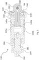
- a tool body 110 of an exemplary crimping tool in accordance with an embodiment is disclosed.
- a crimping tool according to the invention may be used to crimp two cable elements 190 to each other to create both a mechanical and electrical connection.
- Figure 1 illustrates a tool body 110 comprising a first attachment point and a second attachment point, the attachment points are not visible in Figure 1 , reference to Figure 2 is made.
- the tool body 110 further comprises a first guidance element 120 arranged at a first distance from the first attachment point and the second attachment point.
- the tool body 110 also comprises a second guidance element 130 arranged at a second distance from the first guidance element.
- the first attachment point and the second attachment point are arranged on a first side of the first guidance element 120 and the second guidance element 130.
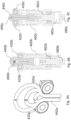
- the crimping tool may further comprise a powering unit configured to increase the first distance so that a diameter of the loop decreases.
- a powering unit may connect to the end of the tool body opposite the loop of the flexible cable 140.
- the powering unit may for example be a hydraulic system comprising a hydraulic fluid that is pressurized and configured to cause the increase of the first distance. Further details are found with relation to the remaining Figures.
- the embodiment of Figure 1 also discloses a mounting structure 160.
- the first guidance element 120 and the second guidance element 130 are attached to the mounting structure 160.
- the mounting structure 160 can help ensuring that the guidance elements 120, 130 are kept in a correct position even when pressure from the flexible cable 140 is added.
- at least one of the first guidance element 120 and the second guidance element 130 may be rotatably attached to the mounting structure 160. This can ensure an easy motion when the flexible cable 140 engaging the guidance elements 120, 130 moves in relation to the guidance elements 120, 130.
- the flexible cable 140 will move in relation to the guidance elements 120, 130 when the powering unit increases the first distance.
- the guidance elements 120, 130 are both rotatably attached to the mounting structure 160 using bearing shafts and roller bearings. Of course, other ways of rotatably fastening the guidance elements are available to a person skilled in the art.
- a tensile strength of 97 MPa may be sufficient for the flexible cable 140 to be able to crimp the cable elements 190 without being damaged. It is understood that for different thickness and material of the cable elements 190 different materials or tensile strengths of the flexible cable 140 may be preferred.
- a first state A the flexible cable 440a has been mounted engaging the guidance elements 420a, 430a and attached to a first and second attachment point.
- the flexible cable 440a has a loop on one side of the guidance elements 420a, 430a with a first diameter.
- a two cable elements for example an electrical conductor or wire and a crimping connector could be fitted in the loop of the flexible cable 440a.
- a third state C the diameter of the loop of the flexible cable 440a has decreased again.
- the distance between the guidance elements 420a, 430a and the attachment points has increased even more which causes the loop to tighten.
- Figure 4A no cable elements are present, so the loop has almost disappeared completely. If cable elements would have been present, they would have been compressed by the continuing decreasing of the diameter of the loop ultimately causing a mechanical and electrical connection between the cable elements.
- the method may further comprise removing the crimping tool from the first cable element and the second cable element after deactivating the powering unit. This may be done by detaching at least one end part of the flexible cable from the crimping tool.
Landscapes
- Engineering & Computer Science (AREA)
- Manufacturing & Machinery (AREA)
- Mechanical Engineering (AREA)
- Manufacturing Of Electrical Connectors (AREA)
- Auxiliary Devices For And Details Of Packaging Control (AREA)
Claims (15)
- Outil de sertissage (100) configuré pour créer un raccordement mécanique et électrique entre un premier élément de câble (190, 490b, 490c) et un second élément de câble (190, 490b, 490c), dans lequel le second élément de câble comprend un conducteur électrique ou un fil, ledit outil de sertissage comprenant :
un corps d'outil (110) comprenant :un premier point d'attache (115a) ;un second point d'attache (115b) ;un premier élément de guidage (120) agencé à une première distance dudit premier point d'attache et dudit second point d'attache ; etun second élément de guidage (130) agencé à une seconde distance dudit premier élément de guidage, dans lequel ledit premier point d'attache et ledit second point d'attache sont agencés sur un premier côté dudit premier élément de guidage et dudit second élément de guidage ;caractérisé par :
un câble flexible (140) comprenant :une première partie d'extrémité (145a) attachée de façon amovible audit premier point d'attache ;une seconde partie d'extrémité (145b) attachée de façon amovible audit second point d'attache, dans lequel ledit câble flexible entre en prise avec ledit premier élément de guidage et ledit second élément de guidage, et dans lequel ledit câble flexible s'étend depuis ledit premier point d'attache jusqu'audit second point d'attache de telle sorte qu'une boucle soit formée sur un second côté dudit premier élément de guidage et dudit second élément de guidage, opposé audit premier côté ; etune unité motrice (150) configurée pour augmenter ladite première distance pour qu'un diamètre de ladite boucle diminue. - Outil de sertissage selon la revendication 1, comprend en outre une structure de montage (160), dans lequel ledit premier élément de guidage et ledit second élément de guidage sont attachés à ladite structure de montage.
- Outil de sertissage selon la revendication 2, dans lequel au moins un dudit premier élément de guidage et dudit second élément de guidage est attaché de façon rotative à ladite structure de montage.
- Outil de sertissage selon la revendication 3, dans lequel ledit au moins un dudit premier élément de guidage et dudit second élément de guidage attaché de façon rotative à ladite structure de montage comprend un disque circulaire avec un renfoncement en forme de U le long d'une circonférence dudit disque circulaire.
- Outil de sertissage selon la revendication 3 ou 4, dans lequel ledit au moins un dudit premier élément de guidage et dudit second élément de guidage attaché de façon rotative à ladite structure de montage comprend un arbre à palier (124, 134) et un palier à rouleaux (128, 138).
- Outil de sertissage selon l'une quelconque des revendications précédentes, dans lequel ladite unité motrice comprend un entraînement hydraulique agencé pour augmenter ladite première distance pour que ledit diamètre de ladite boucle diminue.
- Outil de sertissage selon l'une quelconque des revendications précédentes, dans lequel ladite unité motrice est configurée pour augmenter ladite première distance en éloignant ledit premier point d'attache et ou ledit second point d'attache dudit premier élément de guidage et dudit second élément de guidage.
- Outil de sertissage selon l'une quelconque des revendications 1 à 6, dans lequel ladite unité motrice est configurée pour augmenter ladite première distance en éloignant ledit premier élément de guidage et ledit second élément de guidage dudit premier point d'attache et dudit second point d'attache.
- Outil de sertissage selon la revendication 7 ou 8, dans lequel ledit premier élément de guidage et ledit second élément de guidage sont tous les deux rotatifs et dans lequel ledit premier élément de guidage et ledit second élément de guidage comprennent tous les deux un disque circulaire avec un renfoncement en forme de U le long d'une circonférence dudit disque circulaire.
- Outil de sertissage selon l'une quelconque des revendications précédentes, dans lequel ladite seconde distance est plus grande qu'un rayon dudit câble flexible et plus petite que cinq rayons dudit câble flexible.
- Outil de sertissage selon l'une quelconque des revendications précédentes, dans lequel ledit câble flexible est tressé par des fibres d'un matériau à haute résistance, par exemple une fibre Dyneema.
- Outil de sertissage selon l'une quelconque des revendications précédentes, comprenant en outre une unité de commande configurée pour mesurer un travail réalisé par ladite unité motrice et/ou mesurer de façon continue ladite première distance pour s'assurer que ledit diamètre de ladite boucle a diminué suffisamment pour établir un raccordement mécanique et électrique entre ledit premier élément de câble et ledit second élément de câble.
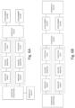
- Procédé pour créer un raccordement mécanique et électrique entre deux éléments de câble en utilisant un outil de sertissage selon l'une quelconque des revendications précédentes, le procédé comprenant :la formation (S1) d'une boucle avec un câble flexible en pliant ledit câble flexible et attachant une première partie d'extrémité à un premier point d'attache dudit outil de sertissage et une seconde partie d'extrémité à une seconde point d'attache dudit outil de sertissage ;l'insertion (S2) d'un premier élément de câble dans ladite boucle ;l'insertion (S3) d'un second élément de câble dans ladite boucle ;l'activation (S4) d'une unité motrice dudit outil de sertissage, configurée pour diminuer un diamètre de ladite boucle pour permettre audit câble flexible d'appliquer une pression sur ledit premier élément de câble et ledit second élément de câble ; etla désactivation (S5) de ladite unité motrice lorsque ledit premier élément de câble et ledit second élément de câble ont été déformés pour qu'un raccordement mécanique et électrique soit établi.
- Procédé selon la revendication 13, dans lequel ledit premier élément de câble est un raccord de sertissage et ledit second élément de câble est inséré dans ledit raccord de sertissage avant l'activation de ladite unité motrice.
- Procédé selon la revendication 13 ou la revendication 14, comprenant en outre l'enlèvement dudit outil de sertissage à partir dudit premier élément de câble et dudit second élément de câble après la désactivation de ladite unité motrice, dans lequel l'enlèvement dudit outil de sertissage est effectué en détachant au moins une partie d'extrémité dudit câble flexible à partir dudit outil de sertissage.
Applications Claiming Priority (1)
| Application Number | Priority Date | Filing Date | Title |
|---|---|---|---|
| SE2150021A SE545083C2 (en) | 2021-01-13 | 2021-01-13 | Crimping tool |
Publications (3)
| Publication Number | Publication Date |
|---|---|
| EP4033616A1 EP4033616A1 (fr) | 2022-07-27 |
| EP4033616B1 true EP4033616B1 (fr) | 2025-01-29 |
| EP4033616C0 EP4033616C0 (fr) | 2025-01-29 |
Family
ID=79317191
Family Applications (1)
| Application Number | Title | Priority Date | Filing Date |
|---|---|---|---|
| EP22151213.0A Active EP4033616B1 (fr) | 2021-01-13 | 2022-01-12 | Outil de sertissage et méthode pour créer une connexion mécanique et électrique entre deux éléments de câble |
Country Status (4)
| Country | Link |
|---|---|
| US (1) | US11721945B2 (fr) |
| EP (1) | EP4033616B1 (fr) |
| CN (1) | CN114765337A (fr) |
| SE (1) | SE545083C2 (fr) |
Citations (2)
| Publication number | Priority date | Publication date | Assignee | Title |
|---|---|---|---|---|
| EP3376612B1 (fr) * | 2017-03-15 | 2020-01-01 | The Boeing Company | Appareil, système et procédé de préhension, de placement et de fusion de manchons de soudure sur des fils et des câbles électriques blindés |
| WO2021018592A1 (fr) * | 2019-07-30 | 2021-02-04 | Metzner Maschinenbau Gmbh | Procédé, dispositif et système de fabrication de câble électrique |
Family Cites Families (9)
| Publication number | Priority date | Publication date | Assignee | Title |
|---|---|---|---|---|
| US3507270A (en) * | 1967-07-05 | 1970-04-21 | Raymond W Ferrier | Occluder for blood vessel or flexible tube |
| US4723434A (en) | 1984-10-29 | 1988-02-09 | Square D Company | Centering device for hydraulic compression tools |
| US5195042A (en) * | 1990-06-27 | 1993-03-16 | Burndy Corporation | Apparatus and method for controlling crimping of articles |
| US20030230132A1 (en) * | 2002-06-17 | 2003-12-18 | Emerson Electric Co. | Crimping apparatus |
| CN107107317B (zh) * | 2014-10-06 | 2019-09-17 | 米沃奇电动工具公司 | 液压电动工具 |
| ITUA20161807A1 (it) * | 2016-03-18 | 2017-09-18 | Cembre Spa | Utensile oleodinamico di compressione o taglio |
| US11292118B2 (en) * | 2018-01-30 | 2022-04-05 | Milwaukee Electric Tool Corporation | Power tool |
| WO2019152689A2 (fr) * | 2018-01-31 | 2019-08-08 | Abb Schweiz Ag | Outil de sertissage à système de communication sans fil |
| CN209217240U (zh) | 2018-11-20 | 2019-08-06 | 孟金国 | 一种电力系统带电操作接线装置 |
-
2021
- 2021-01-13 SE SE2150021A patent/SE545083C2/en unknown
- 2021-12-30 US US17/565,947 patent/US11721945B2/en active Active
-
2022
- 2022-01-11 CN CN202210025930.7A patent/CN114765337A/zh active Pending
- 2022-01-12 EP EP22151213.0A patent/EP4033616B1/fr active Active
Patent Citations (2)
| Publication number | Priority date | Publication date | Assignee | Title |
|---|---|---|---|---|
| EP3376612B1 (fr) * | 2017-03-15 | 2020-01-01 | The Boeing Company | Appareil, système et procédé de préhension, de placement et de fusion de manchons de soudure sur des fils et des câbles électriques blindés |
| WO2021018592A1 (fr) * | 2019-07-30 | 2021-02-04 | Metzner Maschinenbau Gmbh | Procédé, dispositif et système de fabrication de câble électrique |
Also Published As
| Publication number | Publication date |
|---|---|
| CN114765337A (zh) | 2022-07-19 |
| SE2150021A1 (en) | 2022-07-14 |
| US20220224067A1 (en) | 2022-07-14 |
| SE545083C2 (en) | 2023-03-21 |
| EP4033616A1 (fr) | 2022-07-27 |
| EP4033616C0 (fr) | 2025-01-29 |
| US11721945B2 (en) | 2023-08-08 |
Similar Documents
| Publication | Publication Date | Title |
|---|---|---|
| CN105181572B (zh) | 用于分离焊接层的剥离设备和方法 | |
| JP2003519610A (ja) | 引張り部材用の終端装置 | |
| CN117330419B (zh) | 一种具有防护功能的电缆质量检测装置 | |
| EP3238851B1 (fr) | Appareil et procédé de fixation d'un manchon à une extrémité de fil | |
| EP4033616B1 (fr) | Outil de sertissage et méthode pour créer une connexion mécanique et électrique entre deux éléments de câble | |
| US8375527B1 (en) | Actuated wedge socket assembly | |
| CN108247195B (zh) | 钢筋焊接装置以及焊接方法 | |
| WO2013055763A1 (fr) | Ensemble connecteur de câble et procédé de formation de ce dernier | |
| JP3210088U (ja) | 管の牽引装置 | |
| EP3404779A1 (fr) | Procédé de surveillance d'un processus de sertissage | |
| EP0636875A1 (fr) | Méthode et dispositif pour tester la résistance à la torsion des embouts de tubes en carton | |
| US4318290A (en) | Swaging machine for elongated bodies of metal, e.g. end pieces for wires in boat-rigs | |
| CN112320562A (zh) | 一种适用于起吊大型圆柱体的吊具包带压紧机构及吊具 | |
| CN214641579U (zh) | 一种便携式锁管器 | |
| CN210099917U (zh) | 炉辊轴承拆卸装置 | |
| CN116481935A (zh) | 一种纯弯曲试验装置 | |
| GB2053760A (en) | Roll-swaging machine for elongated bodies of metal | |
| CN211924442U (zh) | 一种工程机械液压泵检测装置 | |
| CN216471838U (zh) | 一种万向自动旋转连接装置 | |
| EP3485998B1 (fr) | Sertissage et procédé de production d'un sertissage | |
| CN113218554B (zh) | 一种悬索桥索夹螺杆轴力检测装置及其检测方法 | |
| CN223895392U (zh) | 一种燃气管卡压接头 | |
| CN220503546U (zh) | 一种便于拼接的钢丝绳 | |
| CN213033471U (zh) | 一种拉弯机的型材上下料装置 | |
| CN214611141U (zh) | 钢带卷吊装夹具 |
Legal Events
| Date | Code | Title | Description |
|---|---|---|---|
| PUAI | Public reference made under article 153(3) epc to a published international application that has entered the european phase |
Free format text: ORIGINAL CODE: 0009012 |
|
| STAA | Information on the status of an ep patent application or granted ep patent |
Free format text: STATUS: THE APPLICATION HAS BEEN PUBLISHED |
|
| AK | Designated contracting states |
Kind code of ref document: A1 Designated state(s): AL AT BE BG CH CY CZ DE DK EE ES FI FR GB GR HR HU IE IS IT LI LT LU LV MC MK MT NL NO PL PT RO RS SE SI SK SM TR |
|
| STAA | Information on the status of an ep patent application or granted ep patent |
Free format text: STATUS: REQUEST FOR EXAMINATION WAS MADE |
|
| 17P | Request for examination filed |
Effective date: 20230127 |
|
| RBV | Designated contracting states (corrected) |
Designated state(s): AL AT BE BG CH CY CZ DE DK EE ES FI FR GB GR HR HU IE IS IT LI LT LU LV MC MK MT NL NO PL PT RO RS SE SI SK SM TR |
|
| GRAP | Despatch of communication of intention to grant a patent |
Free format text: ORIGINAL CODE: EPIDOSNIGR1 |
|
| STAA | Information on the status of an ep patent application or granted ep patent |
Free format text: STATUS: GRANT OF PATENT IS INTENDED |
|
| INTG | Intention to grant announced |
Effective date: 20240321 |
|
| GRAJ | Information related to disapproval of communication of intention to grant by the applicant or resumption of examination proceedings by the epo deleted |
Free format text: ORIGINAL CODE: EPIDOSDIGR1 |
|
| STAA | Information on the status of an ep patent application or granted ep patent |
Free format text: STATUS: REQUEST FOR EXAMINATION WAS MADE |
|
| INTC | Intention to grant announced (deleted) | ||
| GRAP | Despatch of communication of intention to grant a patent |
Free format text: ORIGINAL CODE: EPIDOSNIGR1 |
|
| STAA | Information on the status of an ep patent application or granted ep patent |
Free format text: STATUS: GRANT OF PATENT IS INTENDED |
|
| INTG | Intention to grant announced |
Effective date: 20240830 |
|
| GRAS | Grant fee paid |
Free format text: ORIGINAL CODE: EPIDOSNIGR3 |
|
| GRAA | (expected) grant |
Free format text: ORIGINAL CODE: 0009210 |
|
| STAA | Information on the status of an ep patent application or granted ep patent |
Free format text: STATUS: THE PATENT HAS BEEN GRANTED |
|
| AK | Designated contracting states |
Kind code of ref document: B1 Designated state(s): AL AT BE BG CH CY CZ DE DK EE ES FI FR GB GR HR HU IE IS IT LI LT LU LV MC MK MT NL NO PL PT RO RS SE SI SK SM TR |
|
| REG | Reference to a national code |
Ref country code: GB Ref legal event code: FG4D |
|
| REG | Reference to a national code |
Ref country code: CH Ref legal event code: EP |
|
| REG | Reference to a national code |
Ref country code: DE Ref legal event code: R096 Ref document number: 602022009887 Country of ref document: DE |
|
| REG | Reference to a national code |
Ref country code: IE Ref legal event code: FG4D |
|
| U01 | Request for unitary effect filed |
Effective date: 20250217 |
|
| U07 | Unitary effect registered |
Designated state(s): AT BE BG DE DK EE FI FR IT LT LU LV MT NL PT RO SE SI Effective date: 20250221 |
|
| PG25 | Lapsed in a contracting state [announced via postgrant information from national office to epo] |
Ref country code: RS Free format text: LAPSE BECAUSE OF FAILURE TO SUBMIT A TRANSLATION OF THE DESCRIPTION OR TO PAY THE FEE WITHIN THE PRESCRIBED TIME-LIMIT Effective date: 20250429 |
|
| PG25 | Lapsed in a contracting state [announced via postgrant information from national office to epo] |
Ref country code: PL Free format text: LAPSE BECAUSE OF FAILURE TO SUBMIT A TRANSLATION OF THE DESCRIPTION OR TO PAY THE FEE WITHIN THE PRESCRIBED TIME-LIMIT Effective date: 20250129 |
|
| PG25 | Lapsed in a contracting state [announced via postgrant information from national office to epo] |
Ref country code: ES Free format text: LAPSE BECAUSE OF FAILURE TO SUBMIT A TRANSLATION OF THE DESCRIPTION OR TO PAY THE FEE WITHIN THE PRESCRIBED TIME-LIMIT Effective date: 20250129 |
|
| PG25 | Lapsed in a contracting state [announced via postgrant information from national office to epo] |
Ref country code: IS Free format text: LAPSE BECAUSE OF FAILURE TO SUBMIT A TRANSLATION OF THE DESCRIPTION OR TO PAY THE FEE WITHIN THE PRESCRIBED TIME-LIMIT Effective date: 20250529 Ref country code: NO Free format text: LAPSE BECAUSE OF FAILURE TO SUBMIT A TRANSLATION OF THE DESCRIPTION OR TO PAY THE FEE WITHIN THE PRESCRIBED TIME-LIMIT Effective date: 20250429 |
|
| PG25 | Lapsed in a contracting state [announced via postgrant information from national office to epo] |
Ref country code: HR Free format text: LAPSE BECAUSE OF FAILURE TO SUBMIT A TRANSLATION OF THE DESCRIPTION OR TO PAY THE FEE WITHIN THE PRESCRIBED TIME-LIMIT Effective date: 20250129 |
|
| PG25 | Lapsed in a contracting state [announced via postgrant information from national office to epo] |
Ref country code: GR Free format text: LAPSE BECAUSE OF FAILURE TO SUBMIT A TRANSLATION OF THE DESCRIPTION OR TO PAY THE FEE WITHIN THE PRESCRIBED TIME-LIMIT Effective date: 20250430 |
|
| PG25 | Lapsed in a contracting state [announced via postgrant information from national office to epo] |
Ref country code: SM Free format text: LAPSE BECAUSE OF FAILURE TO SUBMIT A TRANSLATION OF THE DESCRIPTION OR TO PAY THE FEE WITHIN THE PRESCRIBED TIME-LIMIT Effective date: 20250129 |
|
| PG25 | Lapsed in a contracting state [announced via postgrant information from national office to epo] |
Ref country code: CZ Free format text: LAPSE BECAUSE OF FAILURE TO SUBMIT A TRANSLATION OF THE DESCRIPTION OR TO PAY THE FEE WITHIN THE PRESCRIBED TIME-LIMIT Effective date: 20250129 |
|
| PG25 | Lapsed in a contracting state [announced via postgrant information from national office to epo] |
Ref country code: SK Free format text: LAPSE BECAUSE OF FAILURE TO SUBMIT A TRANSLATION OF THE DESCRIPTION OR TO PAY THE FEE WITHIN THE PRESCRIBED TIME-LIMIT Effective date: 20250129 |
|
| PLBE | No opposition filed within time limit |
Free format text: ORIGINAL CODE: 0009261 |
|
| STAA | Information on the status of an ep patent application or granted ep patent |
Free format text: STATUS: NO OPPOSITION FILED WITHIN TIME LIMIT |
|
| REG | Reference to a national code |
Ref country code: CH Ref legal event code: L10 Free format text: ST27 STATUS EVENT CODE: U-0-0-L10-L00 (AS PROVIDED BY THE NATIONAL OFFICE) Effective date: 20251210 |
|
| 26N | No opposition filed |
Effective date: 20251030 |
|
| PGFP | Annual fee paid to national office [announced via postgrant information from national office to epo] |
Ref country code: GB Payment date: 20251215 Year of fee payment: 5 |
|
| U20 | Renewal fee for the european patent with unitary effect paid |
Year of fee payment: 5 Effective date: 20251215 |
|
| REG | Reference to a national code |
Ref country code: CH Ref legal event code: U11 Free format text: ST27 STATUS EVENT CODE: U-0-0-U10-U11 (AS PROVIDED BY THE NATIONAL OFFICE) Effective date: 20260201 |
|
| PGFP | Annual fee paid to national office [announced via postgrant information from national office to epo] |
Ref country code: CH Payment date: 20260201 Year of fee payment: 5 |