EP4034334B1 - Machine-outil, en particulier ponceuse, dotée d'un dispositif de chargement - Google Patents
Machine-outil, en particulier ponceuse, dotée d'un dispositif de chargement Download PDFInfo
- Publication number
- EP4034334B1 EP4034334B1 EP19816622.5A EP19816622A EP4034334B1 EP 4034334 B1 EP4034334 B1 EP 4034334B1 EP 19816622 A EP19816622 A EP 19816622A EP 4034334 B1 EP4034334 B1 EP 4034334B1
- Authority
- EP
- European Patent Office
- Prior art keywords
- workpiece
- machine tool
- workpieces
- transport
- transport wheel
- Prior art date
- Legal status (The legal status is an assumption and is not a legal conclusion. Google has not performed a legal analysis and makes no representation as to the accuracy of the status listed.)
- Active
Links
Images

Classifications
-
- B—PERFORMING OPERATIONS; TRANSPORTING
- B24—GRINDING; POLISHING
- B24B—MACHINES, DEVICES, OR PROCESSES FOR GRINDING OR POLISHING; DRESSING OR CONDITIONING OF ABRADING SURFACES; FEEDING OF GRINDING, POLISHING, OR LAPPING AGENTS
- B24B37/00—Lapping machines or devices; Accessories
- B24B37/34—Accessories
- B24B37/345—Feeding, loading or unloading work specially adapted to lapping
-
- B—PERFORMING OPERATIONS; TRANSPORTING
- B23—MACHINE TOOLS; METAL-WORKING NOT OTHERWISE PROVIDED FOR
- B23Q—DETAILS, COMPONENTS, OR ACCESSORIES FOR MACHINE TOOLS, e.g. ARRANGEMENTS FOR COPYING OR CONTROLLING; MACHINE TOOLS IN GENERAL CHARACTERISED BY THE CONSTRUCTION OF PARTICULAR DETAILS OR COMPONENTS; COMBINATIONS OR ASSOCIATIONS OF METAL-WORKING MACHINES, NOT DIRECTED TO A PARTICULAR RESULT
- B23Q7/00—Arrangements for handling work specially combined with or arranged in, or specially adapted for use in connection with, machine tools, e.g. for conveying, loading, positioning, discharging, sorting
- B23Q7/02—Arrangements for handling work specially combined with or arranged in, or specially adapted for use in connection with, machine tools, e.g. for conveying, loading, positioning, discharging, sorting by means of drums or rotating tables or discs
-
- B—PERFORMING OPERATIONS; TRANSPORTING
- B23—MACHINE TOOLS; METAL-WORKING NOT OTHERWISE PROVIDED FOR
- B23Q—DETAILS, COMPONENTS, OR ACCESSORIES FOR MACHINE TOOLS, e.g. ARRANGEMENTS FOR COPYING OR CONTROLLING; MACHINE TOOLS IN GENERAL CHARACTERISED BY THE CONSTRUCTION OF PARTICULAR DETAILS OR COMPONENTS; COMBINATIONS OR ASSOCIATIONS OF METAL-WORKING MACHINES, NOT DIRECTED TO A PARTICULAR RESULT
- B23Q7/00—Arrangements for handling work specially combined with or arranged in, or specially adapted for use in connection with, machine tools, e.g. for conveying, loading, positioning, discharging, sorting
- B23Q7/16—Loading work on to conveyors; Arranging work on conveyors, e.g. varying spacing between individual workpieces
-
- B—PERFORMING OPERATIONS; TRANSPORTING
- B24—GRINDING; POLISHING
- B24B—MACHINES, DEVICES, OR PROCESSES FOR GRINDING OR POLISHING; DRESSING OR CONDITIONING OF ABRADING SURFACES; FEEDING OF GRINDING, POLISHING, OR LAPPING AGENTS
- B24B27/00—Other grinding machines or devices
- B24B27/0069—Other grinding machines or devices with means for feeding the work-pieces to the grinding tool, e.g. turntables, transfer means
-
- B—PERFORMING OPERATIONS; TRANSPORTING
- B24—GRINDING; POLISHING
- B24B—MACHINES, DEVICES, OR PROCESSES FOR GRINDING OR POLISHING; DRESSING OR CONDITIONING OF ABRADING SURFACES; FEEDING OF GRINDING, POLISHING, OR LAPPING AGENTS
- B24B41/00—Component parts such as frames, beds, carriages, headstocks
- B24B41/005—Feeding or manipulating devices specially adapted to grinding machines
-
- B—PERFORMING OPERATIONS; TRANSPORTING
- B24—GRINDING; POLISHING
- B24B—MACHINES, DEVICES, OR PROCESSES FOR GRINDING OR POLISHING; DRESSING OR CONDITIONING OF ABRADING SURFACES; FEEDING OF GRINDING, POLISHING, OR LAPPING AGENTS
- B24B7/00—Machines or devices designed for grinding plane surfaces on work, including polishing plane glass surfaces; Accessories therefor
- B24B7/10—Single-purpose machines or devices
- B24B7/16—Single-purpose machines or devices for grinding end-faces, e.g. of gauges, rollers, nuts, piston rings
- B24B7/17—Single-purpose machines or devices for grinding end-faces, e.g. of gauges, rollers, nuts, piston rings for simultaneously grinding opposite and parallel end faces, e.g. double disc grinders
Definitions
- the invention relates to a machine tool, in particular a grinding machine, with a work area in which a workpiece held in a transport element can be machined, the transport element having a plurality of workpiece holders for holding workpieces to be machined, with a workpiece held in a workpiece holder being moved by means of the transport element into the Working space can be transported in and out of the working space, with a loading device being provided by means of which individual workpieces can each be fed to a workpiece holder of the transport element.
- a grinding machine with the features of the preamble of claim 1 is from KR 102 039 147 B1 known.
- a trained as a double-sided grinding machine machine tool is from DE 37 42 953 C2 known.
- the working space is designed in the form of a gap and is delimited between active surfaces of two grinding wheels that face one another.
- a disc-shaped, rotatable transport element is provided with workpiece holders, each of which is used to hold a workpiece to be ground.
- the DE 37 42 953 C2 To load the workpiece holders, the DE 37 42 953 C2 to store workpieces to be ground in stacks and to release the lower workpiece for transfer to a workpiece holder.
- the present invention is based on the object of creating a machine tool with a simply constructed loading device, which enables rapid loading of a transport element.
- the loading device comprises a transport wheel which can be rotated about a drive axis and which has workpiece holding areas distributed along its circumference, which can be fitted with individual workpieces in a radially inward direction relative to the drive axis and which release individual workpieces in respective workpiece holders of the transport element in a radially outward direction relative to the drive axis.
- the transport wheel according to the invention makes it possible to equip the transport wheel along its circumference with workpieces that are arranged offset relative to one another and to release these workpieces again.
- the transport wheel is loaded with workpieces in relation to the drive axle of the transport wheel in a radially inward direction; a workpiece is released in the opposite direction.
- the loading device has a relatively simple structure and allows workpieces to be transferred from a feed area to a release area by means of comparatively simple kinematics, namely by rotating about the drive axis of the transport wheel.
- the transport wheel it is possible for the transport wheel to be fitted with a workpiece and another workpiece to be released at the same time.
- the loading device enables particularly reliable, tilt-free and fast loading, even of workpieces that still have burrs on their edges.
- At least two, in particular at least three, in particular at least four, in particular at least six, in particular at least eight workpiece holding areas are preferably arranged along the circumference of the transport wheel.
- the workpiece holding areas are preferably spaced equidistantly from one another, as seen along the circumference of the transport wheel.
- a preferred embodiment provides that the drive axle of the transport wheel is aligned horizontally. This not only means an alignment that is exactly horizontal in relation to the direction of gravity, but also an alignment that is inclined by a maximum of 20° with respect to this horizontal.
- the at least essentially horizontal alignment of the drive axle has the advantage that the workpiece holding areas of the transport wheel can move tangentially past an at least essentially horizontally aligned transport element in a lower area of the transport wheel.
- the workpiece holding areas preferably extend in the radial direction in relation to the drive axis, which allows for easy loading of the transport wheel and easy release of the workpieces.
- a workpiece and a workpiece holding area it is possible for a workpiece and a workpiece holding area to interact with one another in a form-fitting manner. In addition or as an alternative to this, however, it is also possible for a workpiece to be held on or in a workpiece holding area by means of magnetic forces.
- a particularly advantageous embodiment provides that the workpiece holding areas have holding pins.
- these enable ring-shaped workpieces to be accommodated, with the retaining pins being able to penetrate an annular space enclosed by the workpiece (for loading of the transport wheel), and the retaining pins can also be guided out of the annular space of the workpiece again (to release the workpiece).
- a first drive device for moving the transport element, a second drive device for rotating the transport wheel and a control device are provided, with the control device controlling the two drive devices in such a way that a movement of the workpiece holders of the transport element and a movement of the workpiece holding areas of the transport wheel are synchronized with each other.
- the workpiece holding areas have holding pins, it is preferred that these holding pins are in meshing engagement with the workpiece receptacles of the transport element.
- the first drive device is a rotary drive device for rotating the transport element about a vertical axis in particular.
- a transport element is formed in particular by the transport disc of a grinding machine, in particular by the transport disc of a double-sided face grinding machine.
- a feed area for feeding workpieces is provided, in which individual workpieces can be kept ready and can each be fed to a workpiece holding area.
- the feed area is preferably arranged adjacent to an upper area of the transport wheel.
- An "upper area of the transport wheel” means an area which, when the drive axis of the transport wheel is not oriented vertically in relation to the direction of gravity, is arranged higher up than other areas of the transport wheel that are located further down.
- the feed area has a support for holding an individual workpiece. This makes it possible for the workpiece holding areas of the transport wheel to be moved into the area of this support and in this way to grasp and take away the individual workpieces held ready on the support.
- the support has a free space or slot that allows a holding pin to penetrate through the support into a space above the support, with this immersion movement being accompanied by the entrainment of a workpiece, in particular a ring-shaped one .
- the feed area has a slip ramp for arranging a supply of workpieces. This allows easy storage of workpieces, which due to gravity slip down the ramp, with the bottom workpiece from the next free workpiece holding area of the transport wheel can be picked up. This type of storage of workpieces is particularly well suited for workpieces that still have burrs on their edges.
- a release area for releasing a workpiece is preferably formed from a lower area of the transport wheel.
- the arrangement of the release area in a lower area of the transport wheel has the advantage that the workpieces can be released with the aid of gravity.
- workpieces held in the workpiece holding areas are not only supported by gravity on their way between the feed area and the release area, but are also moved radially outwards with the aid of centrifugal force, which allows for a further transfer into a workpiece holder of the transport element supported into.
- a retaining device is provided, which is arranged radially outside of the workpiece holders in relation to the drive axis and extends in particular between the feed area and the release area.
- a preferred retaining device has a concavely curved contact surface against which a workpiece to be released rests at least in an area adjacent to the release area. In particular, this is associated with an alignment of the workpieces in a position which corresponds to a receiving position within a workpiece receptacle of the transport element. In this context, it is preferred if an end section of the contact surface is aligned tangentially or at least essentially tangentially in relation to a receiving surface of the transport element.
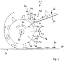
- the machine tool 10 is a face grinding machine, in particular one Double-sided surface grinding machine, with a working space 12, which extends between two grinding wheels, not shown, which process the active surfaces of workpieces 14 facing one another or their end faces 16 and 18 that face away from one another.
- a disc-shaped transport element 20 is provided for handling the workpieces 14 , which is driven to rotate about a vertical axis 24 by means of a first drive device 22 .
- the transport element 20 has a plurality of workpiece holders 26 which are designed in particular in the form of openings in the disc-shaped transport element 20 and each serve to hold a workpiece 14 .
- the workpiece holders 26 are preferably arranged regularly distributed along a pitch circle around the vertical axis 24 .
- a support surface 28 is provided in a manner known per se for supporting the workpieces 14 downwards, which is arranged below the transport element 20 .
- the loading device 32 In order to arrange the workpieces 14 in the workpiece receptacles 26, a loading device 32 discussed below is provided.
- the loading device 32 has a transport wheel 34 which is rotatably driven about a horizontal drive axis 36 by means of a second drive device 38, see figure 2 . It is preferred that the drive axis 36 is radially aligned with respect to the vertical axis 24 .
- the transport wheel 34 has a peripheral surface 38 .
- Workpiece holding areas 40 are provided distributed along the peripheral surface 38 .
- the workpiece holding areas preferably each extend along axes 42 which are radially aligned with respect to the drive axis 36 .
- the workpiece holding areas 40 have holding pins 44, which are preferably designed to be rotationally symmetrical with respect to the axis of extension 42, in particular truncated cone-shaped or cylindrical. Furthermore, the retaining pins 44 preferably each have a rounded portion 46 at their radially outward-pointing free end.
- the machine tool 10 includes a feed area, denoted overall by the reference numeral 48 , which is arranged adjacent to an upper area of the transport wheel 34 in relation to the drive axis 36 of the transport wheel 34 .
- the feed area 48 includes a slide ramp 50, shown in sections, which is arranged inclined relative to the horizontal, namely along a transport direction 51 seen in the direction of the transport wheel 34 downwards.
- the slide ramp 50 has lateral boundaries (not shown in the drawing), the distance between which is slightly greater than a maximum outer diameter of a workpiece 14.
- a supply 52 of a row of workpieces 14 arranged on the slide ramp 50 presses with its weight on the one furthest down arranged workpiece 14.
- the workpiece 14 arranged furthest below lies temporarily with an end face 16 on a support 54.
- the support 54 has a slit-shaped free space 56, into which the retaining pins 44 of the workpiece holding areas 40 of the transport wheel 34 can enter when rotating about the drive axis 36, into an annular space 58 bounded by a workpiece 14, so that rotation of the transport wheel 34 creates a workpiece 14 can be detected by the free end of a retaining pin 44 of a workpiece holding portion 40 and in a Transport direction 60 of the transport wheel 34 can be transported further along the circumference of the transport wheel 34.
- an intermediate part 62 is provided for the transition between the arrangement of a workpiece on the support 54 and an intermediate position in which a workpiece 14 comes to rest with an end face 16 on the peripheral surface 38 of the transport wheel 34 (cf figure 2 )
- this has a support surface 64 which is curved in an arc shape in the direction of the peripheral surface 38 and which supports a workpiece 14 during the transition between the support 54 and contact with the peripheral surface 38 .
- the intermediate element 62 also has a slit-shaped free space 66 which makes it possible for the holding pins 44 of the workpiece holding areas 40 to be guided through the intermediate part 62 without the components mentioned colliding.
- Loading transport wheel 34 can be assisted by arranging a hold-down device, for example a brush, above support 54 and/or intermediate part 62, which counteracts lifting of workpieces 14 from support 54 and/or from intermediate part 62.
- a hold-down device for example a brush
- the workpieces 14 are transferred along the transport direction 60 by moving the peripheral surface 38 and the workpiece holding areas 40 into a lower area of the transport wheel 34 in relation to the drive axis 36, which forms a release area designated overall by the reference numeral 68.
- a retaining device 70 is also effective, which extends radially outwards around the workpiece holding areas 40 of the transport wheel 34 in relation to the transport wheel 34 .
- the retaining pins 44 can sweep past a concavely curved contact surface 72 of the retaining device 70 without making contact, but a distance between the contact surface 72 and the free ends of the retaining pins 44 is selected such that it is smaller than the height of the workpieces 14, which is caused by the distance of the end faces 16 and 18 is determined.
- the distances between the workpiece holding areas 40 of the transport wheel 34 on the one hand and the distances between the workpiece holders 26 of the transport element 20 on the other hand are matched to one another.
- the vertical axis 24 of the transport element 20 is perpendicular to the horizontal drive axis 36 of the transport wheel 34 .
- the holding pins 44 of the workpiece holding areas 40 of the transport wheel 34 mesh with the workpiece receptacles 26 of the transport element 20.
- the drive devices 22 of the transport element 20 and 38 of the transport wheel 34 are synchronized with one another via a control device 74.
- the loading device 32 described above enables workpieces 14 to be loaded quickly and reliably into the workpiece receptacles 26 of the transport element 20.
- the transport wheel 34 could be loaded with three to four workpieces 14 per second.
Landscapes
- Engineering & Computer Science (AREA)
- Mechanical Engineering (AREA)
- Constituent Portions Of Griding Lathes, Driving, Sensing And Control (AREA)
- Feeding Of Workpieces (AREA)
- Grinding Of Cylindrical And Plane Surfaces (AREA)
Claims (13)
- Machine-outil (10), en particulier ponceuse, comprenant un espace de travail (12) dans lequel une pièce à usinée (14) logée dans un élément de transport (20) peut être usinée, dans laquelle l'élément de transport (20) présente plusieurs logements de pièce à usiner (26) pour loger des pièces à usiner (14) devant être usinées, dans laquelle une pièce à usiner (14) logée respectivement dans un logement de pièce (26) peut être transportée au moyen de l'élément de transport (20) jusque dans l'espace de travail (12) et hors de l'espace de travail (12), dans laquelle un dispositif de chargement (32) est prévu, au moyen duquel des pièces à usiner individuelles (14) peuvent être acheminées respectivement jusqu'à un logement de pièce à usiner (26) de l'élément de transport (20), caractérisée en ce que le dispositif de chargement (32) comprend une roue de transport (34) pouvant tourner autour d'un axe d'entraînement (36), qui présente des zones de maintien de pièce à usiner (40) agencées réparties le long de sa circonférence, qui peuvent être équipées de pièces à usiner individuelles (14) dans une direction radialement vers l'intérieur par rapport à l'axe d'entraînement (36) et qui libèrent des pièces à usiner individuelles (14) dans une direction radialement vers l'extérieur par rapport à l'axe d'entraînement (36) jusque dans des logements de pièce à usiner respectifs (26) de l'élément de transport (20).
- Machine-outil (10) selon la revendication 1, caractérisée en ce que l'axe d'entraînement (36) de la roue de transport (34) est orienté horizontalement.
- Machine-outil (10) selon l'une quelconque des revendications précédentes, caractérisée en ce que les zones de maintien de pièce à usiner (40) s'étendent dans une direction radiale par rapport à l'axe d'entraînement (36).
- Machine-outil (10) selon l'une quelconque des revendications précédentes, caractérisée en ce que les zones de maintien de pièce à usiner (40) présentent des goupilles de maintien (44).
- Machine-outil (10) selon l'une quelconque des revendications précédentes, caractérisée en ce qu'un premier dispositif d'entraînement (22) pour déplacer l'élément de transport (20), un second dispositif d'entraînement (38) pour faire tourner la roue de transport (34) et un dispositif de commande (74) sont prévus, dans laquelle le dispositif de commande (74) commande les deux dispositifs d'entraînement (22, 38) de telle sorte qu'un déplacement des logements de pièce à usiner (26) de l'élément de transport (20) et un déplacement des zones de maintien de pièce à usiner (40) de la roue de transport (34) sont synchronisés l'un avec l'autre.
- Machine-outil (10) selon la revendication 5, caractérisée en ce que le premier dispositif d'entraînement (22) est un dispositif d'entraînement en rotation pour faire tourner l'élément de transport (20) en particulier autour d'un axe vertical (24).
- Machine-outil (10) selon l'une quelconque des revendications précédentes, caractérisée en ce qu'une zone d'alimentation (48) est prévue pour alimenter des pièces à usiner (14), dans laquelle des pièces à usiner (14) peuvent être mises à disposition de manière séparée et peuvent être alimentées respectivement vers une zone de maintien de pièce à usiner (40).
- Machine-outil (10) selon la revendication 7, caractérisée en ce que la zone d'alimentation (48) est agencée adjacente à une zone supérieure de la roue de transport (34).
- Machine-outil (10) selon la revendication 7 ou 8, caractérisée en ce que la zone d'alimentation (48) présente un support (54) pour mettre à disposition une pièce à usiner individuelle (14).
- Machine-outil (10) selon l'une quelconque des revendications 7 à 9, caractérisée en ce que la zone d'alimentation (48) présente une rampe de glissement (50) pour agencer une réserve (52) de pièces à usiner (14).
- Machine-outil (10) selon l'une quelconque des revendications précédentes, caractérisée en ce qu'une zone de libération (68) est formée pour libérer une pièce à usiner (14) depuis une zone inférieure de la roue de transport (34).
- Machine-outil (10) selon l'une quelconque des revendications précédentes, caractérisée en ce qu'un dispositif de de retenue (70) est prévu, qui est agencé radialement à l'extérieur des logements de pièce à usiner (40) par rapport à l'axe d'entraînement (36).
- Machine-outil (10) selon la revendication 12, caractérisée en ce que le dispositif de retenue (70) présente une surface d'appui (72) incurvée de manière concave contre laquelle une pièce à usiner (14) devant être libérée repose au moins dans une zone adjacente à la zone de libération (68).
Applications Claiming Priority (1)
| Application Number | Priority Date | Filing Date | Title |
|---|---|---|---|
| PCT/EP2019/083545 WO2021110249A1 (fr) | 2019-12-03 | 2019-12-03 | Machine-outil, en particulier ponceuse, dotée d'un dispositif de chargement |
Publications (2)
| Publication Number | Publication Date |
|---|---|
| EP4034334A1 EP4034334A1 (fr) | 2022-08-03 |
| EP4034334B1 true EP4034334B1 (fr) | 2023-01-18 |
Family
ID=68808350
Family Applications (1)
| Application Number | Title | Priority Date | Filing Date |
|---|---|---|---|
| EP19816622.5A Active EP4034334B1 (fr) | 2019-12-03 | 2019-12-03 | Machine-outil, en particulier ponceuse, dotée d'un dispositif de chargement |
Country Status (2)
| Country | Link |
|---|---|
| EP (1) | EP4034334B1 (fr) |
| WO (1) | WO2021110249A1 (fr) |
Families Citing this family (1)
| Publication number | Priority date | Publication date | Assignee | Title |
|---|---|---|---|---|
| DE102022202512A1 (de) | 2022-03-14 | 2023-09-14 | Volkswagen Aktiengesellschaft | Wendeanlage sowie Verfahren zum Wenden eines Werkstücks mittels dieser Wendeanlage |
Citations (3)
| Publication number | Priority date | Publication date | Assignee | Title |
|---|---|---|---|---|
| JPS5020294U (fr) * | 1973-06-16 | 1975-03-07 | ||
| EP2260975A1 (fr) * | 2009-06-10 | 2010-12-15 | Supfina Grieshaber GmbH & Co. KG | Rectifieuse plane et procédé de traitement de pièce usinée par rectification plane |
| EP2301714B1 (fr) * | 2009-09-23 | 2011-11-30 | Supfina Grieshaber GmbH & Co. KG | Rectifieuse plane et procédé de fonctionnement et/ou d'entretien d'une rectifieuse plane |
Family Cites Families (4)
| Publication number | Priority date | Publication date | Assignee | Title |
|---|---|---|---|---|
| DE3742953A1 (de) | 1987-12-18 | 1989-06-29 | Hahn & Kolb | Beladeeinrichtung fuer vielfachwerkstueckhalter |
| DE502008000963D1 (de) * | 2008-08-29 | 2010-08-26 | Supfina Grieshaber Gmbh & Co | Vorrichtung zur Fein- oder Feinstbearbeitung von Werkstücken |
| CN103878652A (zh) * | 2014-03-24 | 2014-06-25 | 乳山市宏远机床制造有限公司 | 一种双端面磨床专用圆盘式送料装置 |
| KR102039147B1 (ko) * | 2019-03-20 | 2019-10-31 | (주)오성지엠 | 연삭부품 공급장치 |
-
2019
- 2019-12-03 WO PCT/EP2019/083545 patent/WO2021110249A1/fr not_active Ceased
- 2019-12-03 EP EP19816622.5A patent/EP4034334B1/fr active Active
Patent Citations (3)
| Publication number | Priority date | Publication date | Assignee | Title |
|---|---|---|---|---|
| JPS5020294U (fr) * | 1973-06-16 | 1975-03-07 | ||
| EP2260975A1 (fr) * | 2009-06-10 | 2010-12-15 | Supfina Grieshaber GmbH & Co. KG | Rectifieuse plane et procédé de traitement de pièce usinée par rectification plane |
| EP2301714B1 (fr) * | 2009-09-23 | 2011-11-30 | Supfina Grieshaber GmbH & Co. KG | Rectifieuse plane et procédé de fonctionnement et/ou d'entretien d'une rectifieuse plane |
Also Published As
| Publication number | Publication date |
|---|---|
| EP4034334A1 (fr) | 2022-08-03 |
| WO2021110249A1 (fr) | 2021-06-10 |
Similar Documents
| Publication | Publication Date | Title |
|---|---|---|
| DE10061063B4 (de) | Verfahren und Vorrichtung zur Zuführung von regelmäßigen Gegenständen zu einer Arbeitsstation | |
| DE3644854A1 (de) | Werkstueckhalter | |
| DE3605470A1 (de) | Mehrflaechenbearbeitungs-werkzeugmaschine | |
| DE2510827C2 (de) | Foerdereinrichtung fuer zylinderbloecke oder aehnliche werkstuecke durch eine schleuderstrahlanlage | |
| DE3247586C2 (fr) | ||
| EP4034334B1 (fr) | Machine-outil, en particulier ponceuse, dotée d'un dispositif de chargement | |
| EP0266646B1 (fr) | Magasin d'outils pour machines-outils et procédé pour son utilisation | |
| EP2260975B1 (fr) | Rectifieuse plane et procédé de traitement de pièce usinée par rectification plane | |
| EP1430992A1 (fr) | Appareil pour transférer des pièces plattes avec un bras rotatif mobile en translation | |
| DE4111545A1 (de) | Rundtaktautomat | |
| DE4100148C2 (fr) | ||
| DE19704200A1 (de) | Einrichtung zum Wenden von Dosenkörpern | |
| EP0328958A2 (fr) | Dispositif d'usinage de surfaces de pièces à symétrie de révolution | |
| WO2006108516A1 (fr) | Dispositif et un procédé pour amener des éléments mécaniques | |
| DE2161575A1 (de) | Stapeleinrichtung für Pakete | |
| DE3310535C2 (fr) | ||
| DE4109877C2 (fr) | ||
| EP1255625B1 (fr) | Dispositif de traitement de lames de scie circulaires | |
| DE484109C (de) | Vorrichtung zum Zufuehren von kantigen Werkstuecken fuer Werkzeugmaschinen | |
| DE102021119083A1 (de) | Fertigungssystem und Verfahren zur schleifenden Bearbeitung einer ersten Stirnseite einer Kegelrolle | |
| DE2830923A1 (de) | Vorrichtung zur foerderung duenner gegenstaende | |
| DE410820C (de) | Vorrichtung zum Fraesen von Gewinde an Schrauben, insbesondere Holzschrauben | |
| EP3294508B1 (fr) | Dispositif d'alimentation en pièces et dipositif d'évacuation des pièces | |
| EP4124410A1 (fr) | Dispositif d'alimentation en pièces pour une machine à rectifier | |
| CH471624A (de) | Arbeitsstelle in einer Montagestrasse zur automatischen Durchführung von Arbeiten nacheinander an einer Serie von Kleinapparaten |
Legal Events
| Date | Code | Title | Description |
|---|---|---|---|
| STAA | Information on the status of an ep patent application or granted ep patent |
Free format text: STATUS: UNKNOWN |
|
| STAA | Information on the status of an ep patent application or granted ep patent |
Free format text: STATUS: THE INTERNATIONAL PUBLICATION HAS BEEN MADE |
|
| PUAI | Public reference made under article 153(3) epc to a published international application that has entered the european phase |
Free format text: ORIGINAL CODE: 0009012 |
|
| STAA | Information on the status of an ep patent application or granted ep patent |
Free format text: STATUS: REQUEST FOR EXAMINATION WAS MADE |
|
| 17P | Request for examination filed |
Effective date: 20220428 |
|
| AK | Designated contracting states |
Kind code of ref document: A1 Designated state(s): AL AT BE BG CH CY CZ DE DK EE ES FI FR GB GR HR HU IE IS IT LI LT LU LV MC MK MT NL NO PL PT RO RS SE SI SK SM TR |
|
| GRAP | Despatch of communication of intention to grant a patent |
Free format text: ORIGINAL CODE: EPIDOSNIGR1 |
|
| STAA | Information on the status of an ep patent application or granted ep patent |
Free format text: STATUS: GRANT OF PATENT IS INTENDED |
|
| DAV | Request for validation of the european patent (deleted) | ||
| DAX | Request for extension of the european patent (deleted) | ||
| INTG | Intention to grant announced |
Effective date: 20220908 |
|
| GRAS | Grant fee paid |
Free format text: ORIGINAL CODE: EPIDOSNIGR3 |
|
| GRAA | (expected) grant |
Free format text: ORIGINAL CODE: 0009210 |
|
| STAA | Information on the status of an ep patent application or granted ep patent |
Free format text: STATUS: THE PATENT HAS BEEN GRANTED |
|
| AK | Designated contracting states |
Kind code of ref document: B1 Designated state(s): AL AT BE BG CH CY CZ DE DK EE ES FI FR GB GR HR HU IE IS IT LI LT LU LV MC MK MT NL NO PL PT RO RS SE SI SK SM TR |
|
| REG | Reference to a national code |
Ref country code: GB Ref legal event code: FG4D Free format text: NOT ENGLISH |
|
| REG | Reference to a national code |
Ref country code: DE Ref legal event code: R096 Ref document number: 502019006852 Country of ref document: DE |
|
| REG | Reference to a national code |
Ref country code: CH Ref legal event code: EP |
|
| REG | Reference to a national code |
Ref country code: AT Ref legal event code: REF Ref document number: 1544417 Country of ref document: AT Kind code of ref document: T Effective date: 20230215 Ref country code: IE Ref legal event code: FG4D Free format text: LANGUAGE OF EP DOCUMENT: GERMAN |
|
| REG | Reference to a national code |
Ref country code: LT Ref legal event code: MG9D |
|
| REG | Reference to a national code |
Ref country code: NL Ref legal event code: MP Effective date: 20230118 |
|
| PG25 | Lapsed in a contracting state [announced via postgrant information from national office to epo] |
Ref country code: NL Free format text: LAPSE BECAUSE OF FAILURE TO SUBMIT A TRANSLATION OF THE DESCRIPTION OR TO PAY THE FEE WITHIN THE PRESCRIBED TIME-LIMIT Effective date: 20230118 |
|
| P01 | Opt-out of the competence of the unified patent court (upc) registered |
Effective date: 20230621 |
|
| PG25 | Lapsed in a contracting state [announced via postgrant information from national office to epo] |
Ref country code: RS Free format text: LAPSE BECAUSE OF FAILURE TO SUBMIT A TRANSLATION OF THE DESCRIPTION OR TO PAY THE FEE WITHIN THE PRESCRIBED TIME-LIMIT Effective date: 20230118 Ref country code: PT Free format text: LAPSE BECAUSE OF FAILURE TO SUBMIT A TRANSLATION OF THE DESCRIPTION OR TO PAY THE FEE WITHIN THE PRESCRIBED TIME-LIMIT Effective date: 20230518 Ref country code: NO Free format text: LAPSE BECAUSE OF FAILURE TO SUBMIT A TRANSLATION OF THE DESCRIPTION OR TO PAY THE FEE WITHIN THE PRESCRIBED TIME-LIMIT Effective date: 20230418 Ref country code: LV Free format text: LAPSE BECAUSE OF FAILURE TO SUBMIT A TRANSLATION OF THE DESCRIPTION OR TO PAY THE FEE WITHIN THE PRESCRIBED TIME-LIMIT Effective date: 20230118 Ref country code: LT Free format text: LAPSE BECAUSE OF FAILURE TO SUBMIT A TRANSLATION OF THE DESCRIPTION OR TO PAY THE FEE WITHIN THE PRESCRIBED TIME-LIMIT Effective date: 20230118 Ref country code: HR Free format text: LAPSE BECAUSE OF FAILURE TO SUBMIT A TRANSLATION OF THE DESCRIPTION OR TO PAY THE FEE WITHIN THE PRESCRIBED TIME-LIMIT Effective date: 20230118 Ref country code: ES Free format text: LAPSE BECAUSE OF FAILURE TO SUBMIT A TRANSLATION OF THE DESCRIPTION OR TO PAY THE FEE WITHIN THE PRESCRIBED TIME-LIMIT Effective date: 20230118 |
|
| PG25 | Lapsed in a contracting state [announced via postgrant information from national office to epo] |
Ref country code: SE Free format text: LAPSE BECAUSE OF FAILURE TO SUBMIT A TRANSLATION OF THE DESCRIPTION OR TO PAY THE FEE WITHIN THE PRESCRIBED TIME-LIMIT Effective date: 20230118 Ref country code: PL Free format text: LAPSE BECAUSE OF FAILURE TO SUBMIT A TRANSLATION OF THE DESCRIPTION OR TO PAY THE FEE WITHIN THE PRESCRIBED TIME-LIMIT Effective date: 20230118 Ref country code: IS Free format text: LAPSE BECAUSE OF FAILURE TO SUBMIT A TRANSLATION OF THE DESCRIPTION OR TO PAY THE FEE WITHIN THE PRESCRIBED TIME-LIMIT Effective date: 20230518 Ref country code: GR Free format text: LAPSE BECAUSE OF FAILURE TO SUBMIT A TRANSLATION OF THE DESCRIPTION OR TO PAY THE FEE WITHIN THE PRESCRIBED TIME-LIMIT Effective date: 20230419 Ref country code: FI Free format text: LAPSE BECAUSE OF FAILURE TO SUBMIT A TRANSLATION OF THE DESCRIPTION OR TO PAY THE FEE WITHIN THE PRESCRIBED TIME-LIMIT Effective date: 20230118 |
|
| REG | Reference to a national code |
Ref country code: DE Ref legal event code: R097 Ref document number: 502019006852 Country of ref document: DE |
|
| PG25 | Lapsed in a contracting state [announced via postgrant information from national office to epo] |
Ref country code: SM Free format text: LAPSE BECAUSE OF FAILURE TO SUBMIT A TRANSLATION OF THE DESCRIPTION OR TO PAY THE FEE WITHIN THE PRESCRIBED TIME-LIMIT Effective date: 20230118 Ref country code: RO Free format text: LAPSE BECAUSE OF FAILURE TO SUBMIT A TRANSLATION OF THE DESCRIPTION OR TO PAY THE FEE WITHIN THE PRESCRIBED TIME-LIMIT Effective date: 20230118 Ref country code: EE Free format text: LAPSE BECAUSE OF FAILURE TO SUBMIT A TRANSLATION OF THE DESCRIPTION OR TO PAY THE FEE WITHIN THE PRESCRIBED TIME-LIMIT Effective date: 20230118 Ref country code: DK Free format text: LAPSE BECAUSE OF FAILURE TO SUBMIT A TRANSLATION OF THE DESCRIPTION OR TO PAY THE FEE WITHIN THE PRESCRIBED TIME-LIMIT Effective date: 20230118 Ref country code: CZ Free format text: LAPSE BECAUSE OF FAILURE TO SUBMIT A TRANSLATION OF THE DESCRIPTION OR TO PAY THE FEE WITHIN THE PRESCRIBED TIME-LIMIT Effective date: 20230118 |
|
| PLBE | No opposition filed within time limit |
Free format text: ORIGINAL CODE: 0009261 |
|
| STAA | Information on the status of an ep patent application or granted ep patent |
Free format text: STATUS: NO OPPOSITION FILED WITHIN TIME LIMIT |
|
| PG25 | Lapsed in a contracting state [announced via postgrant information from national office to epo] |
Ref country code: SK Free format text: LAPSE BECAUSE OF FAILURE TO SUBMIT A TRANSLATION OF THE DESCRIPTION OR TO PAY THE FEE WITHIN THE PRESCRIBED TIME-LIMIT Effective date: 20230118 |
|
| 26N | No opposition filed |
Effective date: 20231019 |
|
| PG25 | Lapsed in a contracting state [announced via postgrant information from national office to epo] |
Ref country code: SI Free format text: LAPSE BECAUSE OF FAILURE TO SUBMIT A TRANSLATION OF THE DESCRIPTION OR TO PAY THE FEE WITHIN THE PRESCRIBED TIME-LIMIT Effective date: 20230118 |
|
| PG25 | Lapsed in a contracting state [announced via postgrant information from national office to epo] |
Ref country code: LU Free format text: LAPSE BECAUSE OF NON-PAYMENT OF DUE FEES Effective date: 20231203 |
|
| PG25 | Lapsed in a contracting state [announced via postgrant information from national office to epo] |
Ref country code: MC Free format text: LAPSE BECAUSE OF FAILURE TO SUBMIT A TRANSLATION OF THE DESCRIPTION OR TO PAY THE FEE WITHIN THE PRESCRIBED TIME-LIMIT Effective date: 20230118 |
|
| GBPC | Gb: european patent ceased through non-payment of renewal fee |
Effective date: 20231203 |
|
| REG | Reference to a national code |
Ref country code: BE Ref legal event code: MM Effective date: 20231231 |
|
| PG25 | Lapsed in a contracting state [announced via postgrant information from national office to epo] |
Ref country code: MC Free format text: LAPSE BECAUSE OF FAILURE TO SUBMIT A TRANSLATION OF THE DESCRIPTION OR TO PAY THE FEE WITHIN THE PRESCRIBED TIME-LIMIT Effective date: 20230118 Ref country code: LU Free format text: LAPSE BECAUSE OF NON-PAYMENT OF DUE FEES Effective date: 20231203 |
|
| REG | Reference to a national code |
Ref country code: IE Ref legal event code: MM4A |
|
| PG25 | Lapsed in a contracting state [announced via postgrant information from national office to epo] |
Ref country code: IE Free format text: LAPSE BECAUSE OF NON-PAYMENT OF DUE FEES Effective date: 20231203 |
|
| PG25 | Lapsed in a contracting state [announced via postgrant information from national office to epo] |
Ref country code: GB Free format text: LAPSE BECAUSE OF NON-PAYMENT OF DUE FEES Effective date: 20231203 |
|
| PG25 | Lapsed in a contracting state [announced via postgrant information from national office to epo] |
Ref country code: BE Free format text: LAPSE BECAUSE OF NON-PAYMENT OF DUE FEES Effective date: 20231231 |
|
| PG25 | Lapsed in a contracting state [announced via postgrant information from national office to epo] |
Ref country code: IE Free format text: LAPSE BECAUSE OF NON-PAYMENT OF DUE FEES Effective date: 20231203 Ref country code: GB Free format text: LAPSE BECAUSE OF NON-PAYMENT OF DUE FEES Effective date: 20231203 Ref country code: BE Free format text: LAPSE BECAUSE OF NON-PAYMENT OF DUE FEES Effective date: 20231231 |
|
| PG25 | Lapsed in a contracting state [announced via postgrant information from national office to epo] |
Ref country code: BG Free format text: LAPSE BECAUSE OF FAILURE TO SUBMIT A TRANSLATION OF THE DESCRIPTION OR TO PAY THE FEE WITHIN THE PRESCRIBED TIME-LIMIT Effective date: 20230118 |
|
| PG25 | Lapsed in a contracting state [announced via postgrant information from national office to epo] |
Ref country code: BG Free format text: LAPSE BECAUSE OF FAILURE TO SUBMIT A TRANSLATION OF THE DESCRIPTION OR TO PAY THE FEE WITHIN THE PRESCRIBED TIME-LIMIT Effective date: 20230118 |
|
| PG25 | Lapsed in a contracting state [announced via postgrant information from national office to epo] |
Ref country code: CY Free format text: LAPSE BECAUSE OF FAILURE TO SUBMIT A TRANSLATION OF THE DESCRIPTION OR TO PAY THE FEE WITHIN THE PRESCRIBED TIME-LIMIT; INVALID AB INITIO Effective date: 20191203 |
|
| PG25 | Lapsed in a contracting state [announced via postgrant information from national office to epo] |
Ref country code: HU Free format text: LAPSE BECAUSE OF FAILURE TO SUBMIT A TRANSLATION OF THE DESCRIPTION OR TO PAY THE FEE WITHIN THE PRESCRIBED TIME-LIMIT; INVALID AB INITIO Effective date: 20191203 |
|
| PG25 | Lapsed in a contracting state [announced via postgrant information from national office to epo] |
Ref country code: TR Free format text: LAPSE BECAUSE OF FAILURE TO SUBMIT A TRANSLATION OF THE DESCRIPTION OR TO PAY THE FEE WITHIN THE PRESCRIBED TIME-LIMIT Effective date: 20230118 |
|
| REG | Reference to a national code |
Ref country code: CH Ref legal event code: U11 Free format text: ST27 STATUS EVENT CODE: U-0-0-U10-U11 (AS PROVIDED BY THE NATIONAL OFFICE) Effective date: 20260101 |
|
| PGFP | Annual fee paid to national office [announced via postgrant information from national office to epo] |
Ref country code: FR Payment date: 20251218 Year of fee payment: 7 |
|
| REG | Reference to a national code |
Ref country code: AT Ref legal event code: MM01 Ref document number: 1544417 Country of ref document: AT Kind code of ref document: T Effective date: 20241203 |
|
| PGFP | Annual fee paid to national office [announced via postgrant information from national office to epo] |
Ref country code: DE Payment date: 20251222 Year of fee payment: 7 |
|
| PG25 | Lapsed in a contracting state [announced via postgrant information from national office to epo] |
Ref country code: AT Free format text: LAPSE BECAUSE OF NON-PAYMENT OF DUE FEES Effective date: 20241203 |
|
| PGFP | Annual fee paid to national office [announced via postgrant information from national office to epo] |
Ref country code: AT Payment date: 20260410 Year of fee payment: 5 |
|
| PGFP | Annual fee paid to national office [announced via postgrant information from national office to epo] |
Ref country code: IT Payment date: 20251231 Year of fee payment: 7 |
|
| PGFP | Annual fee paid to national office [announced via postgrant information from national office to epo] |
Ref country code: CH Payment date: 20260101 Year of fee payment: 7 |