EP4034701B1 - Appareil de séchage de linge et procédé de fonctionnement d'un tel appareil - Google Patents
Appareil de séchage de linge et procédé de fonctionnement d'un tel appareil Download PDFInfo
- Publication number
- EP4034701B1 EP4034701B1 EP20781446.8A EP20781446A EP4034701B1 EP 4034701 B1 EP4034701 B1 EP 4034701B1 EP 20781446 A EP20781446 A EP 20781446A EP 4034701 B1 EP4034701 B1 EP 4034701B1
- Authority
- EP
- European Patent Office
- Prior art keywords
- air
- appliance
- drying
- heat pump
- condenser
- Prior art date
- Legal status (The legal status is an assumption and is not a legal conclusion. Google has not performed a legal analysis and makes no representation as to the accuracy of the status listed.)
- Active
Links
Images

Classifications
-
- D—TEXTILES; PAPER
- D06—TREATMENT OF TEXTILES OR THE LIKE; LAUNDERING; FLEXIBLE MATERIALS NOT OTHERWISE PROVIDED FOR
- D06F—LAUNDERING, DRYING, IRONING, PRESSING OR FOLDING TEXTILE ARTICLES
- D06F58/00—Domestic laundry dryers
- D06F58/30—Drying processes
-
- D—TEXTILES; PAPER
- D06—TREATMENT OF TEXTILES OR THE LIKE; LAUNDERING; FLEXIBLE MATERIALS NOT OTHERWISE PROVIDED FOR
- D06F—LAUNDERING, DRYING, IRONING, PRESSING OR FOLDING TEXTILE ARTICLES
- D06F58/00—Domestic laundry dryers
- D06F58/20—General details of domestic laundry dryers
- D06F58/206—Heat pump arrangements
-
- D—TEXTILES; PAPER
- D06—TREATMENT OF TEXTILES OR THE LIKE; LAUNDERING; FLEXIBLE MATERIALS NOT OTHERWISE PROVIDED FOR
- D06F—LAUNDERING, DRYING, IRONING, PRESSING OR FOLDING TEXTILE ARTICLES
- D06F58/00—Domestic laundry dryers
- D06F58/20—General details of domestic laundry dryers
- D06F58/24—Condensing arrangements
-
- D—TEXTILES; PAPER
- D06—TREATMENT OF TEXTILES OR THE LIKE; LAUNDERING; FLEXIBLE MATERIALS NOT OTHERWISE PROVIDED FOR
- D06F—LAUNDERING, DRYING, IRONING, PRESSING OR FOLDING TEXTILE ARTICLES
- D06F58/00—Domestic laundry dryers
- D06F58/32—Control of operations performed in domestic laundry dryers
- D06F58/34—Control of operations performed in domestic laundry dryers characterised by the purpose or target of the control
- D06F58/48—Control of the energy consumption
-
- D—TEXTILES; PAPER
- D06—TREATMENT OF TEXTILES OR THE LIKE; LAUNDERING; FLEXIBLE MATERIALS NOT OTHERWISE PROVIDED FOR
- D06F—LAUNDERING, DRYING, IRONING, PRESSING OR FOLDING TEXTILE ARTICLES
- D06F2105/00—Systems or parameters controlled or affected by the control systems of washing machines, washer-dryers or laundry dryers
- D06F2105/26—Heat pumps
-
- Y—GENERAL TAGGING OF NEW TECHNOLOGICAL DEVELOPMENTS; GENERAL TAGGING OF CROSS-SECTIONAL TECHNOLOGIES SPANNING OVER SEVERAL SECTIONS OF THE IPC; TECHNICAL SUBJECTS COVERED BY FORMER USPC CROSS-REFERENCE ART COLLECTIONS [XRACs] AND DIGESTS
- Y02—TECHNOLOGIES OR APPLICATIONS FOR MITIGATION OR ADAPTATION AGAINST CLIMATE CHANGE
- Y02B—CLIMATE CHANGE MITIGATION TECHNOLOGIES RELATED TO BUILDINGS, e.g. HOUSING, HOUSE APPLIANCES OR RELATED END-USER APPLICATIONS
- Y02B40/00—Technologies aiming at improving the efficiency of home appliances, e.g. induction cooking or efficient technologies for refrigerators, freezers or dish washers
Definitions
- the invention relates to a device for drying laundry, having a device housing, at least one open drying air duct arranged within the device housing for sucking in ambient air during a drying process, and at least one heat pump arranged within the device housing and thermally coupled to the drying air duct, wherein the drying air duct has at least one air intake opening arranged within the device housing, which is arranged on a section of the drying air duct that is connected upstream of a condenser of the heat pump with respect to an air mass flow through the drying air duct that occurs during the drying process.
- the invention further relates to a method for operating a device for drying laundry, wherein a condenser of a heat pump of the device arranged within a device housing of the device is supplied with an air mass flow that consists partly of ambient air that is sucked in by means of an open drying air duct of the device that is thermally coupled to the heat pump, and partly of air sucked in within the device housing.
- a device of the type mentioned above is, for example, made of EP 2 196 577 A1 known.
- the drying air is sucked from the surroundings of the device and, after entering the device housing, through a condenser of the heat pump.
- the ambient air sucked in is heated as it flows through the condenser and then flows further in the direction of a fan of the drying air duct.
- the heated drying air is compressed in the fan and fed by the fan into a laundry drum or a container of the device that surrounds the laundry drum radially on the outside and at the back.
- the drying air inside the laundry drum is cooled and loaded with water vapor.
- drying air flows from the laundry drum through a filter unit of the drying air duct, through an evaporator of the heat pump and, if required, through an additional heat exchanger of the heat pump and then leaves the device.
- parts of the drying air enter the interior of the device through leaks at a front and rear drum seal. device housing. This leakage air leads to a deterioration of the condensation rate of the drying process, to a lengthening of the drying process and thus also to a lengthening of the power consumption of the device, which in turn leads to higher energy consumption.
- US 2019 / 0 145 043 A1 discloses a dryer provided with an air circulation channel.
- the air circulation channel defines a recirculation loop with a laundry drum of the dryer.
- the air circulation channel may define a predetermined leakage opening in fluid communication between the recirculation loop and the interior volume of the housing.
- a heat exchanger portion of the dryer is disposed along the air circulation channel in thermal communication with air within the recirculation loop.
- WO 2018 / 123 845 A1 discloses a dryer with a housing, a laundry drum, a heat pump, an air circulation channel connected to the laundry drum and a fan provided in the air circulation channel.
- the dryer has an exhaust air channel through which drying air is discharged from the dryer and an inlet channel through which ambient air enters the air circulation channel.
- the exhaust air channel is connected to the inlet channel via a connecting channel.
- One object of the invention is to reduce the energy consumption of a laundry drying appliance.
- leakage air is removed via the air intake opening of the drying air duct arranged inside the device housing. sucked into the drying air duct within the device housing, mixed with the ambient air from the area around the device sucked into the drying air duct and fed together with this ambient air to the condenser of the heat pump. This allows energy losses caused by air leaks in the drying air duct within the device housing to be incorporated back into the ongoing drying process.
- mixed air is generated whose enthalpy is higher than the enthalpy of the ambient air by the amount of the enthalpy of the leakage air.
- the invention thus achieves an improvement in the performance values of a device for drying laundry with a heat pump and an open drying air duct.
- the drying air circuit can also have two or more air intake openings according to the invention.
- the drying air duct has at least one fan for conveying air through the drying air duct during a drying process.
- a section of the drying air duct is formed by a container of the device in which a laundry drum is rotatably accommodated.
- the heat pump in addition to an evaporator, has an additional heat exchanger which is connected downstream of the evaporator with respect to the air mass flow through the drying air duct and which is connected upstream of an expansion unit of the refrigerant circuit directly with respect to a refrigerant flow through a refrigerant circuit of the heat pump or indirectly via the condenser.
- the appliance for drying laundry can be designed, for example, as a tumble dryer, washer-dryer or the like.
- the air intake opening is connected via an air intake duct to a region of a floor assembly of the device, which is arranged separately from a heat exchanger receiving region of the floor assembly and in which at least one compressor of the heat pump is arranged.
- the heat exchanger receiving area can enclose the heat exchangers of the heat pump like a housing in order to ensure that the drying air flows around and/or through the heat exchangers in the desired manner.
- An expansion unit of the heat pump can also be arranged in the area of the floor assembly arranged separately from the heat exchanger receiving area.
- the air intake channel can run through a partition wall between the heat exchanger receiving area and the area of the floor assembly that is separate from this.
- the additional heat exchanger is designed as a subcooler downstream of the condenser or as a desuperheater upstream of the condenser. These designs of the additional heat exchanger differ in the piping of the heat pump required for their use.
- an air mass flow is supplied to a condenser of a heat pump of the device arranged within a device housing of the device, which air mass flow consists partly of ambient air that is sucked in by means of an open drying air duct of the device that is thermally coupled to the heat pump, and partly of air sucked in within the device housing, wherein air emerging from a container of the drying air duct that accommodates a laundry drum of the device is additionally heated by means of an additional heat exchanger of the heat pump, which is connected downstream of an evaporator of the heat pump with respect to an air mass flow through the drying air duct and which is connected upstream of an expansion unit of the heat pump directly or indirectly via the condenser with respect to a coolant flow through a coolant circuit of the heat pump.
- the device can be used according to one of the above-mentioned embodiments or a combination of at least two of these embodiments with one another to carry out the method.
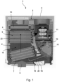
- Fig. 1 shows a schematic sectional view of an embodiment of an inventive device 1 for drying laundry.
- a horizontal section of a base group 2 of the device 1 is shown.
- the device 1 has a device housing 3 accommodating the base group 2, an open drying air duct 4 arranged within the device housing 3 for sucking in ambient air according to the arrow 5 during a drying process and a heat pump 6 arranged within the device housing 3 and thermally coupled to the drying air duct 4.
- the heat pump 6 has a condenser 7, an evaporator 9 downstream of the condenser 7 with respect to an air mass flow through the drying air duct 4 indicated by the arrow 23, and an additional heat exchanger 10 downstream of the evaporator 9 with respect to the air mass flow through the drying air duct 4, which additional heat exchanger 10 is connected directly upstream of an expansion unit 17 of the refrigerant circuit 11 with respect to a refrigerant flow through a refrigerant circuit 11 of the heat pump 6 and downstream of the condenser 7.
- the heat pump 6 also has a compressor 12.
- the condenser 7, the evaporator 9 and the additional heat exchanger 10 are arranged in a manner not shown in a heat pump region 13 which is closed radially on the outside with respect to the air mass flow and is thus separate from a region 14 of the floor assembly 2 in which the compressor 12 and the expansion unit are arranged.
- the additional heat exchanger 10 can be designed as a subcooler.
- the drying air duct 4 has an air intake opening 15 arranged within the device housing 3, which is arranged in a section of the drying air duct 4 that is connected upstream of the condenser 7 of the heat pump 6 with respect to the air mass flow through the drying air duct 4 during the drying process.
- the air intake opening 15 is connected via an air intake duct 16 to the area 14 of the base group 2, which is arranged separately from the heat exchanger receiving area 13 of the base group 2. Leakage air is sucked in within the device housing 3 via the air intake duct 16 in accordance with the arrow 20.
- Fig. 2 shows a process diagram of the Fig. 1 shown device 1.
- the expansion unit 17 of the heat pump 6 and a container 18 are also shown, which accommodates a laundry drum (not shown).
- Ambient air flows into the device 1 according to arrow 5 and is passed through the device 1 or its in Fig. 2 not shown drying air duct, for which a fan (not shown) is used.
- the air exiting from the additional heat exchanger 10 is discharged from the device 1 according to arrow 19.
- leakage air sucked in from within the device housing (not shown) is additionally fed to the sucked in ambient air.
Landscapes
- Engineering & Computer Science (AREA)
- Textile Engineering (AREA)
- Detail Structures Of Washing Machines And Dryers (AREA)
Claims (4)
- Appareil (1) de séchage du linge, comprenant un boîtier d'appareil (3), au moins un conduit d'air de séchage (4) ouvert disposé à l'intérieur du boîtier d'appareil (3) pour aspirer de l'air ambiant pendant un processus de séchage et au moins une pompe à chaleur (6) disposée à l'intérieur du boîtier d'appareil (3), couplée thermiquement au conduit d'air de séchage (4),dans lequel le conduit d'air de séchage (4) comprend au moins un orifice d'aspiration d'air (15) disposé à l'intérieur du boîtier d'appareil (3), qui est disposé sur une section du conduit d'air de séchage (4), laquelle est disposée en amont d'un condenseur (7) de la pompe à chaleur (6) par rapport à un flux massique d'air délivré pendant le processus de séchage à travers le conduit d'air de séchage (4),caractérisé en ce que la pompe à chaleur (6) comprend, outre un évaporateur (9), un échangeur de chaleur auxiliaire (10) disposé en aval de l'évaporateur (9) par rapport au flux massique d'air à travers le conduit d'air de séchage (4), qui est disposé en amont d'une unité de détente (17) du circuit d'agent réfrigérant (11) directement ou indirectement par l'intermédiaire du condenseur (7), par rapport à un flux d'agent réfrigérant à travers un circuit d'agent réfrigérant (11) de la pompe à chaleur (6).
- Appareil (1) selon la revendication 1, caractérisé en ce que l'orifice d'aspiration d'air (15) est relié en communication avec une partie (14) d'un groupe de plancher (2) de l'appareil (1) par l'intermédiaire d'un canal d'aspiration d'air (16), qui est agencée séparément d'une partie de logement d'échangeur de chaleur (13) du groupe de plancher (2) et est disposée dans l'au moins un compresseur (12) de la pompe à chaleur (6).
- Appareil (1) selon la revendication 1 ou 2, caractérisé en ce que l'échangeur de chaleur auxiliaire (10) est conçu sous forme d'un sous-refroidisseur disposé en aval du condenseur (7) ou d'un désurchauffeur disposé en amont du condenseur (7).
- Procédé de fonctionnement d'un appareil (1) de séchage du linge, dans lequel un flux massique d'air est amené à un condenseur (7) d'une pompe à chaleur (6) de l'appareil (1) disposée à l'intérieur d'un boîtier (3) de l'appareil (1), qui est composé en partie d'un air ambiant, qui est aspiré au moyen d'un conduit d'air de séchage (4) de l'appareil (1) ouvert couplé thermiquement à la pompe à chaleur (6), et en partie d'un air aspiré à l'intérieur du boîtier d'appareil (3),
caractérisé en ce que de l'air sortant d'une cuve (18) du conduit d'air de séchage (4), qui loge un tambour à linge de l'appareil (1), est réchauffé en plus au moyen d'un échangeur de chaleur auxiliaire (10) de la pompe à chaleur (6), qui est disposé en aval d'un évaporateur (9) de la pompe à chaleur (6) par rapport à un flux massique d'air à travers le conduit d'air de séchage (4) et est disposé en amont d'une unité de détente (17) de la pompe à chaleur directement ou indirectement par l'intermédiaire du condenseur (7), par rapport à un flux d'agent réfrigérant à travers un circuit d'agent réfrigérant (11) de la pompe à chaleur (6).
Applications Claiming Priority (2)
| Application Number | Priority Date | Filing Date | Title |
|---|---|---|---|
| DE102019214687.2A DE102019214687A1 (de) | 2019-09-25 | 2019-09-25 | Gerät zum Trocknen von Wäsche und Verfahren zum Betreiben eines solchen Geräts |
| PCT/EP2020/075947 WO2021058365A1 (fr) | 2019-09-25 | 2020-09-17 | Appareil de séchage de linge et procédé de fonctionnement d'un tel appareil |
Publications (2)
| Publication Number | Publication Date |
|---|---|
| EP4034701A1 EP4034701A1 (fr) | 2022-08-03 |
| EP4034701B1 true EP4034701B1 (fr) | 2024-11-13 |
Family
ID=72670676
Family Applications (1)
| Application Number | Title | Priority Date | Filing Date |
|---|---|---|---|
| EP20781446.8A Active EP4034701B1 (fr) | 2019-09-25 | 2020-09-17 | Appareil de séchage de linge et procédé de fonctionnement d'un tel appareil |
Country Status (5)
| Country | Link |
|---|---|
| US (1) | US20220341085A1 (fr) |
| EP (1) | EP4034701B1 (fr) |
| CN (1) | CN114514347B (fr) |
| DE (1) | DE102019214687A1 (fr) |
| WO (1) | WO2021058365A1 (fr) |
Families Citing this family (4)
| Publication number | Priority date | Publication date | Assignee | Title |
|---|---|---|---|---|
| DE102019214687A1 (de) * | 2019-09-25 | 2021-03-25 | BSH Hausgeräte GmbH | Gerät zum Trocknen von Wäsche und Verfahren zum Betreiben eines solchen Geräts |
| DE102020126056A1 (de) | 2020-10-06 | 2022-04-07 | Miele & Cie. Kg | Wärmetauschervorrichtung für eine Wäschebehandlungsmaschine und Bodenmodul für eine Wäschebehandlungsmaschine |
| BE1029652B1 (de) * | 2021-08-03 | 2023-03-06 | Miele & Cie | Wärmetauschervorrichtung für ein Wärmepumpenmodul für einen Wärmepumpentrockner, Wärmepumpenmodul, Wärmepumpentrockner, Verfahren zum Herstellen und Verfahren zum Betreiben einer Wärmetauschervorrichtung |
| US12247346B2 (en) | 2021-12-21 | 2025-03-11 | Whirlpool Corporation | Dryer with external vent |
Family Cites Families (30)
| Publication number | Priority date | Publication date | Assignee | Title |
|---|---|---|---|---|
| US3922798A (en) * | 1974-08-19 | 1975-12-02 | Gen Electric | Clothes dryer |
| US4621438A (en) * | 1980-12-04 | 1986-11-11 | Donald M. Thompson | Energy efficient clothes dryer |
| US4603489A (en) * | 1984-10-05 | 1986-08-05 | Michael Goldberg | Heat pump closed loop drying |
| US6094835A (en) * | 1998-12-14 | 2000-08-01 | University Of Central Florida | Heat pump dryer with desciccant enhanced moisture removal |
| US7526879B2 (en) * | 2005-11-04 | 2009-05-05 | Lg Electronics Inc. | Drum washing machine and clothes dryer using peltier thermoelectric module |
| DK3379152T3 (da) * | 2006-04-18 | 2021-06-14 | Oy Halton Group Ltd | Madlavningsapparat og fremgangsmåde til transport af varmeenergi fra en madlavningsudsugningshætte |
| DE102007018787A1 (de) * | 2007-04-20 | 2008-10-23 | BSH Bosch und Siemens Hausgeräte GmbH | Verfahren zum Betrieb eines Kondensationstrockners mit einer Wärmepumpe, sowie hierzu geeigneter Kondensationstrockner |
| JP2009006126A (ja) * | 2007-05-31 | 2009-01-15 | Panasonic Corp | 衣類乾燥装置 |
| DE102008040853A1 (de) * | 2008-07-30 | 2010-02-04 | BSH Bosch und Siemens Hausgeräte GmbH | Kondensationstrockner mit einer Wärmepumpe und Erkennung eines unzulässigen Betriebszustands sowie Verfahren zu seinem Betrieb |
| DE102008044277A1 (de) * | 2008-12-02 | 2010-06-10 | BSH Bosch und Siemens Hausgeräte GmbH | Trockner mit einer Wärmepumpe und einer elektrischen Heizung sowie Verfahren zu seinem Betrieb |
| DE102008054548A1 (de) * | 2008-12-11 | 2010-06-17 | BSH Bosch und Siemens Hausgeräte GmbH | Trockner mit Umluftanteil sowie Verfahren zu seinem Betrieb |
| PL2957671T3 (pl) * | 2009-06-29 | 2019-03-29 | Electrolux Home Products Corporation N.V. | Urządzenie do suszenia materiałów pranych |
| DE102009055206A1 (de) * | 2009-12-22 | 2011-06-30 | BSH Bosch und Siemens Hausgeräte GmbH, 81739 | Hausgerät mit Wärmepumpenkreislauf |
| EP2468946B1 (fr) * | 2010-12-27 | 2014-05-07 | Electrolux Home Products Corporation N.V. | Système de pompe à chaleur pour sèche-linge et procédé de fonctionnement d'un sèche-linge à pompe à chaleur |
| EP2489775A1 (fr) * | 2011-02-18 | 2012-08-22 | Electrolux Home Products Corporation N.V. | Sèche-linge à pompe à chaleur et procédé de fonctionnement d'un sèche-linge à pompe à chaleur |
| EP2594688B1 (fr) * | 2011-11-21 | 2016-08-31 | Electrolux Home Products Corporation N.V. | Sèche-linge avec système de pompe à chaleur |
| EP2733254A1 (fr) * | 2012-11-16 | 2014-05-21 | Electrolux Home Products Corporation N.V. | Appareil de traitement de linge de pompe à chaleur et procédé de fonctionnement d'un appareil de traitement de linge de pompe à chaleur |
| EP2843119B1 (fr) * | 2013-08-30 | 2017-10-11 | Electrolux Appliances Aktiebolag | Appareil traitement du linge ayant un système de prévention de surchauffe |
| US20160168777A1 (en) * | 2014-12-10 | 2016-06-16 | Electrolux Appliances Aktiebolag | Vented Dryer With Modular Heat Pump Subassembly |
| DE102014225806A1 (de) * | 2014-12-15 | 2016-06-16 | BSH Hausgeräte GmbH | Haushaltsgerät zum Trocknen von Wäsche |
| CN105862371B (zh) * | 2016-05-26 | 2019-11-22 | 无锡小天鹅电器有限公司 | 干衣机和干衣机的控制方法 |
| EP3252217B1 (fr) * | 2016-05-31 | 2020-10-21 | Wuxi Little Swan Electric Co., Ltd. | Boîtier de montage de pompe à chaleur pour séchoir à pompe à chaleur ou machine à laver séchante à pompe à chaleur |
| PL3255203T3 (pl) * | 2016-06-09 | 2020-07-13 | BSH Hausgeräte GmbH | Urządzenie gospodarstwa domowego zawierające pompę ciepła |
| WO2018123845A1 (fr) * | 2016-12-28 | 2018-07-05 | パナソニックIpマネジメント株式会社 | Sèche-linge |
| US10494756B2 (en) * | 2017-11-16 | 2019-12-03 | Haier Us Appliance Solutions, Inc. | Dryer appliances including an air circulation duct |
| DE102018201257A1 (de) * | 2018-01-29 | 2019-08-01 | BSH Hausgeräte GmbH | Gerät zum Trocknen von Wäsche und Verfahren zum Betreiben einer Wärmepumpe eines solchen Geräts |
| DE102018203158A1 (de) * | 2018-03-02 | 2019-09-05 | BSH Hausgeräte GmbH | Gerät zum Trocknen von Wäsche |
| CN113195822B (zh) * | 2018-12-21 | 2023-08-01 | 伊莱克斯家用电器股份公司 | 衣物干燥机 |
| DE102019214687A1 (de) * | 2019-09-25 | 2021-03-25 | BSH Hausgeräte GmbH | Gerät zum Trocknen von Wäsche und Verfahren zum Betreiben eines solchen Geräts |
| US12522970B2 (en) * | 2023-07-26 | 2026-01-13 | Haier Us Appliance Solutions, Inc. | Door assembly for a combination laundry appliance |
-
2019
- 2019-09-25 DE DE102019214687.2A patent/DE102019214687A1/de active Pending
-
2020
- 2020-09-17 EP EP20781446.8A patent/EP4034701B1/fr active Active
- 2020-09-17 US US17/762,822 patent/US20220341085A1/en not_active Abandoned
- 2020-09-17 CN CN202080067529.9A patent/CN114514347B/zh active Active
- 2020-09-17 WO PCT/EP2020/075947 patent/WO2021058365A1/fr not_active Ceased
Also Published As
| Publication number | Publication date |
|---|---|
| CN114514347B (zh) | 2024-02-06 |
| US20220341085A1 (en) | 2022-10-27 |
| DE102019214687A1 (de) | 2021-03-25 |
| CN114514347A (zh) | 2022-05-17 |
| WO2021058365A1 (fr) | 2021-04-01 |
| EP4034701A1 (fr) | 2022-08-03 |
Similar Documents
| Publication | Publication Date | Title |
|---|---|---|
| DE60101445T2 (de) | Wäschetrockner mit Wärmepumpe | |
| DE602004003710T2 (de) | Klimaregelungssystem mit einem dampfkompressionskreislauf in kombination mit einem absorptionskreislauf | |
| WO2021058365A1 (fr) | Appareil de séchage de linge et procédé de fonctionnement d'un tel appareil | |
| DE102008047447B4 (de) | Ölabscheider und Kältemittelkompressor mit diesem | |
| DE112006001946T5 (de) | Trommelartige Wasch-/Trocknermaschine | |
| DE2529577A1 (de) | Kombinierte trommelwasch- und trockeneinrichtung | |
| WO2008110449A1 (fr) | Séchoir à récupération de chaleur et procédé de fonctionnement | |
| DE102007057766A1 (de) | Ablufttrockner mit einer Wärmepumpe und einem ersten Gebläse | |
| DE102007052839A1 (de) | Trockner mit Wärmepumpenkreis | |
| DE102007013997A1 (de) | Kondensationstrockner und Verfahren zum Betreiben eines Kondensationstrockners | |
| DE102008029922A1 (de) | Raumlufttechnisches Gerät und Verfahren zur Verwendung eines solchen raumlufttechnischen Gerätes | |
| DE102008004457A1 (de) | Trockner mit einer Wärmepumpe und einem Gebläse | |
| EP2203586B1 (fr) | Sécheur avec répartiteur de condensat, et procédé pour le faire fonctionner | |
| EP2160488B1 (fr) | Sécheur à condensation muni d'une pompe à chaleur, et procédé pour le faire fonctionner | |
| DE10042230A1 (de) | Axiallüfter | |
| DE102011007715A1 (de) | Wäschetrockner mit einer Trommel und einer Wärmepumpe | |
| DE102004030025A1 (de) | Kühlkreisvorrichtung | |
| DE69632345T2 (de) | Verfahren und vorrichtung zur kuehlung eines schaltschranks | |
| DE102007042969B4 (de) | Trockner mit Wärmerückgewinnung und Umluftanteil | |
| DE102010028741A1 (de) | Ablufttrockner mit Wärmerückgewinnungsaggregat | |
| EP2075368B1 (fr) | Procédé d'élimination d'un condensat dans un appareil ménager d'entretien du linge | |
| EP2055826A1 (fr) | Sèche-linge à évacuation d'air doté d'une récupération de chaleur et cuve de condensation ainsi que son procédé de fonctionnement | |
| DE102010028441A1 (de) | Waschtrockner mit einer Wärmepumpe und Verfahren zu seinem Betrieb | |
| DE3543722A1 (de) | Waeschetrockner | |
| DE102009011673B4 (de) | Wäschetrockner mit kontinuierlicher Wärmerückgewinnung |
Legal Events
| Date | Code | Title | Description |
|---|---|---|---|
| STAA | Information on the status of an ep patent application or granted ep patent |
Free format text: STATUS: UNKNOWN |
|
| STAA | Information on the status of an ep patent application or granted ep patent |
Free format text: STATUS: THE INTERNATIONAL PUBLICATION HAS BEEN MADE |
|
| PUAI | Public reference made under article 153(3) epc to a published international application that has entered the european phase |
Free format text: ORIGINAL CODE: 0009012 |
|
| STAA | Information on the status of an ep patent application or granted ep patent |
Free format text: STATUS: REQUEST FOR EXAMINATION WAS MADE |
|
| 17P | Request for examination filed |
Effective date: 20220425 |
|
| AK | Designated contracting states |
Kind code of ref document: A1 Designated state(s): AL AT BE BG CH CY CZ DE DK EE ES FI FR GB GR HR HU IE IS IT LI LT LU LV MC MK MT NL NO PL PT RO RS SE SI SK SM TR |
|
| DAV | Request for validation of the european patent (deleted) | ||
| DAX | Request for extension of the european patent (deleted) | ||
| GRAP | Despatch of communication of intention to grant a patent |
Free format text: ORIGINAL CODE: EPIDOSNIGR1 |
|
| STAA | Information on the status of an ep patent application or granted ep patent |
Free format text: STATUS: GRANT OF PATENT IS INTENDED |
|
| INTG | Intention to grant announced |
Effective date: 20240709 |
|
| RIC1 | Information provided on ipc code assigned before grant |
Ipc: D06F 58/48 20200101ALI20240628BHEP Ipc: D06F 58/20 20060101AFI20240628BHEP |
|
| GRAS | Grant fee paid |
Free format text: ORIGINAL CODE: EPIDOSNIGR3 |
|
| GRAA | (expected) grant |
Free format text: ORIGINAL CODE: 0009210 |
|
| STAA | Information on the status of an ep patent application or granted ep patent |
Free format text: STATUS: THE PATENT HAS BEEN GRANTED |
|
| AK | Designated contracting states |
Kind code of ref document: B1 Designated state(s): AL AT BE BG CH CY CZ DE DK EE ES FI FR GB GR HR HU IE IS IT LI LT LU LV MC MK MT NL NO PL PT RO RS SE SI SK SM TR |
|
| REG | Reference to a national code |
Ref country code: GB Ref legal event code: FG4D Free format text: NOT ENGLISH |
|
| REG | Reference to a national code |
Ref country code: CH Ref legal event code: EP |
|
| REG | Reference to a national code |
Ref country code: DE Ref legal event code: R096 Ref document number: 502020009752 Country of ref document: DE |
|
| REG | Reference to a national code |
Ref country code: IE Ref legal event code: FG4D Free format text: LANGUAGE OF EP DOCUMENT: GERMAN |
|
| REG | Reference to a national code |
Ref country code: LT Ref legal event code: MG9D |
|
| REG | Reference to a national code |
Ref country code: NL Ref legal event code: MP Effective date: 20241113 |
|
| PG25 | Lapsed in a contracting state [announced via postgrant information from national office to epo] |
Ref country code: IS Free format text: LAPSE BECAUSE OF FAILURE TO SUBMIT A TRANSLATION OF THE DESCRIPTION OR TO PAY THE FEE WITHIN THE PRESCRIBED TIME-LIMIT Effective date: 20250313 Ref country code: PT Free format text: LAPSE BECAUSE OF FAILURE TO SUBMIT A TRANSLATION OF THE DESCRIPTION OR TO PAY THE FEE WITHIN THE PRESCRIBED TIME-LIMIT Effective date: 20250313 Ref country code: HR Free format text: LAPSE BECAUSE OF FAILURE TO SUBMIT A TRANSLATION OF THE DESCRIPTION OR TO PAY THE FEE WITHIN THE PRESCRIBED TIME-LIMIT Effective date: 20241113 |
|
| PG25 | Lapsed in a contracting state [announced via postgrant information from national office to epo] |
Ref country code: FI Free format text: LAPSE BECAUSE OF FAILURE TO SUBMIT A TRANSLATION OF THE DESCRIPTION OR TO PAY THE FEE WITHIN THE PRESCRIBED TIME-LIMIT Effective date: 20241113 Ref country code: NL Free format text: LAPSE BECAUSE OF FAILURE TO SUBMIT A TRANSLATION OF THE DESCRIPTION OR TO PAY THE FEE WITHIN THE PRESCRIBED TIME-LIMIT Effective date: 20241113 |
|
| PG25 | Lapsed in a contracting state [announced via postgrant information from national office to epo] |
Ref country code: BG Free format text: LAPSE BECAUSE OF FAILURE TO SUBMIT A TRANSLATION OF THE DESCRIPTION OR TO PAY THE FEE WITHIN THE PRESCRIBED TIME-LIMIT Effective date: 20241113 |
|
| PG25 | Lapsed in a contracting state [announced via postgrant information from national office to epo] |
Ref country code: ES Free format text: LAPSE BECAUSE OF FAILURE TO SUBMIT A TRANSLATION OF THE DESCRIPTION OR TO PAY THE FEE WITHIN THE PRESCRIBED TIME-LIMIT Effective date: 20241113 |
|
| PG25 | Lapsed in a contracting state [announced via postgrant information from national office to epo] |
Ref country code: NO Free format text: LAPSE BECAUSE OF FAILURE TO SUBMIT A TRANSLATION OF THE DESCRIPTION OR TO PAY THE FEE WITHIN THE PRESCRIBED TIME-LIMIT Effective date: 20250213 |
|
| PG25 | Lapsed in a contracting state [announced via postgrant information from national office to epo] |
Ref country code: LV Free format text: LAPSE BECAUSE OF FAILURE TO SUBMIT A TRANSLATION OF THE DESCRIPTION OR TO PAY THE FEE WITHIN THE PRESCRIBED TIME-LIMIT Effective date: 20241113 Ref country code: GR Free format text: LAPSE BECAUSE OF FAILURE TO SUBMIT A TRANSLATION OF THE DESCRIPTION OR TO PAY THE FEE WITHIN THE PRESCRIBED TIME-LIMIT Effective date: 20250214 |
|
| PG25 | Lapsed in a contracting state [announced via postgrant information from national office to epo] |
Ref country code: PL Free format text: LAPSE BECAUSE OF FAILURE TO SUBMIT A TRANSLATION OF THE DESCRIPTION OR TO PAY THE FEE WITHIN THE PRESCRIBED TIME-LIMIT Effective date: 20241113 |
|
| PG25 | Lapsed in a contracting state [announced via postgrant information from national office to epo] |
Ref country code: RS Free format text: LAPSE BECAUSE OF FAILURE TO SUBMIT A TRANSLATION OF THE DESCRIPTION OR TO PAY THE FEE WITHIN THE PRESCRIBED TIME-LIMIT Effective date: 20250213 |
|
| PG25 | Lapsed in a contracting state [announced via postgrant information from national office to epo] |
Ref country code: SM Free format text: LAPSE BECAUSE OF FAILURE TO SUBMIT A TRANSLATION OF THE DESCRIPTION OR TO PAY THE FEE WITHIN THE PRESCRIBED TIME-LIMIT Effective date: 20241113 |
|
| PG25 | Lapsed in a contracting state [announced via postgrant information from national office to epo] |
Ref country code: DK Free format text: LAPSE BECAUSE OF FAILURE TO SUBMIT A TRANSLATION OF THE DESCRIPTION OR TO PAY THE FEE WITHIN THE PRESCRIBED TIME-LIMIT Effective date: 20241113 |
|
| PG25 | Lapsed in a contracting state [announced via postgrant information from national office to epo] |
Ref country code: EE Free format text: LAPSE BECAUSE OF FAILURE TO SUBMIT A TRANSLATION OF THE DESCRIPTION OR TO PAY THE FEE WITHIN THE PRESCRIBED TIME-LIMIT Effective date: 20241113 |
|
| PG25 | Lapsed in a contracting state [announced via postgrant information from national office to epo] |
Ref country code: RO Free format text: LAPSE BECAUSE OF FAILURE TO SUBMIT A TRANSLATION OF THE DESCRIPTION OR TO PAY THE FEE WITHIN THE PRESCRIBED TIME-LIMIT Effective date: 20241113 |
|
| PG25 | Lapsed in a contracting state [announced via postgrant information from national office to epo] |
Ref country code: SK Free format text: LAPSE BECAUSE OF FAILURE TO SUBMIT A TRANSLATION OF THE DESCRIPTION OR TO PAY THE FEE WITHIN THE PRESCRIBED TIME-LIMIT Effective date: 20241113 |
|
| PG25 | Lapsed in a contracting state [announced via postgrant information from national office to epo] |
Ref country code: CZ Free format text: LAPSE BECAUSE OF FAILURE TO SUBMIT A TRANSLATION OF THE DESCRIPTION OR TO PAY THE FEE WITHIN THE PRESCRIBED TIME-LIMIT Effective date: 20241113 |
|
| PG25 | Lapsed in a contracting state [announced via postgrant information from national office to epo] |
Ref country code: IT Free format text: LAPSE BECAUSE OF FAILURE TO SUBMIT A TRANSLATION OF THE DESCRIPTION OR TO PAY THE FEE WITHIN THE PRESCRIBED TIME-LIMIT Effective date: 20241113 |
|
| REG | Reference to a national code |
Ref country code: DE Ref legal event code: R097 Ref document number: 502020009752 Country of ref document: DE |
|
| PG25 | Lapsed in a contracting state [announced via postgrant information from national office to epo] |
Ref country code: SE Free format text: LAPSE BECAUSE OF FAILURE TO SUBMIT A TRANSLATION OF THE DESCRIPTION OR TO PAY THE FEE WITHIN THE PRESCRIBED TIME-LIMIT Effective date: 20241113 |
|
| PLBE | No opposition filed within time limit |
Free format text: ORIGINAL CODE: 0009261 |
|
| STAA | Information on the status of an ep patent application or granted ep patent |
Free format text: STATUS: NO OPPOSITION FILED WITHIN TIME LIMIT |
|
| PGFP | Annual fee paid to national office [announced via postgrant information from national office to epo] |
Ref country code: DE Payment date: 20250930 Year of fee payment: 6 |
|
| PGFP | Annual fee paid to national office [announced via postgrant information from national office to epo] |
Ref country code: TR Payment date: 20250910 Year of fee payment: 6 |
|
| 26N | No opposition filed |
Effective date: 20250814 |
|
| REG | Reference to a national code |
Ref country code: CH Ref legal event code: H13 Free format text: ST27 STATUS EVENT CODE: U-0-0-H10-H13 (AS PROVIDED BY THE NATIONAL OFFICE) Effective date: 20260504 |
|
| PG25 | Lapsed in a contracting state [announced via postgrant information from national office to epo] |
Ref country code: LU Free format text: LAPSE BECAUSE OF NON-PAYMENT OF DUE FEES Effective date: 20250917 |
|
| GBPC | Gb: european patent ceased through non-payment of renewal fee |
Effective date: 20250917 |
|
| REG | Reference to a national code |
Ref country code: BE Ref legal event code: MM Effective date: 20250930 |
|
| PG25 | Lapsed in a contracting state [announced via postgrant information from national office to epo] |
Ref country code: LT Free format text: LAPSE BECAUSE OF FAILURE TO SUBMIT A TRANSLATION OF THE DESCRIPTION OR TO PAY THE FEE WITHIN THE PRESCRIBED TIME-LIMIT Effective date: 20241113 |
|
| PG25 | Lapsed in a contracting state [announced via postgrant information from national office to epo] |
Ref country code: MC Free format text: LAPSE BECAUSE OF FAILURE TO SUBMIT A TRANSLATION OF THE DESCRIPTION OR TO PAY THE FEE WITHIN THE PRESCRIBED TIME-LIMIT Effective date: 20241113 |
|
| PG25 | Lapsed in a contracting state [announced via postgrant information from national office to epo] |
Ref country code: GB Free format text: LAPSE BECAUSE OF NON-PAYMENT OF DUE FEES Effective date: 20250917 |
|
| PG25 | Lapsed in a contracting state [announced via postgrant information from national office to epo] |
Ref country code: BE Free format text: LAPSE BECAUSE OF NON-PAYMENT OF DUE FEES Effective date: 20250930 Ref country code: CH Free format text: LAPSE BECAUSE OF NON-PAYMENT OF DUE FEES Effective date: 20250930 Ref country code: IE Free format text: LAPSE BECAUSE OF NON-PAYMENT OF DUE FEES Effective date: 20250917 |
|
| PG25 | Lapsed in a contracting state [announced via postgrant information from national office to epo] |
Ref country code: FR Free format text: LAPSE BECAUSE OF NON-PAYMENT OF DUE FEES Effective date: 20250930 |