EP4034708B1 - Procédé de fabrication du corps de voie ferrée et corps de voie ferrée formé par ce procédé - Google Patents
Procédé de fabrication du corps de voie ferrée et corps de voie ferrée formé par ce procédé Download PDFInfo
- Publication number
- EP4034708B1 EP4034708B1 EP20781461.7A EP20781461A EP4034708B1 EP 4034708 B1 EP4034708 B1 EP 4034708B1 EP 20781461 A EP20781461 A EP 20781461A EP 4034708 B1 EP4034708 B1 EP 4034708B1
- Authority
- EP
- European Patent Office
- Prior art keywords
- liquid
- layer
- track
- track bed
- track body
- Prior art date
- Legal status (The legal status is an assumption and is not a legal conclusion. Google has not performed a legal analysis and makes no representation as to the accuracy of the status listed.)
- Active
Links
Images

Classifications
-
- E—FIXED CONSTRUCTIONS
- E01—CONSTRUCTION OF ROADS, RAILWAYS, OR BRIDGES
- E01B—PERMANENT WAY; PERMANENT-WAY TOOLS; MACHINES FOR MAKING RAILWAYS OF ALL KINDS
- E01B1/00—Ballastway; Other means for supporting the sleepers or the track; Drainage of the ballastway
- E01B1/001—Track with ballast
-
- E—FIXED CONSTRUCTIONS
- E01—CONSTRUCTION OF ROADS, RAILWAYS, OR BRIDGES
- E01B—PERMANENT WAY; PERMANENT-WAY TOOLS; MACHINES FOR MAKING RAILWAYS OF ALL KINDS
- E01B27/00—Placing, renewing, working, cleaning, or taking-up the ballast, with or without concurrent work on the track; Devices therefor; Packing sleepers
-
- E—FIXED CONSTRUCTIONS
- E01—CONSTRUCTION OF ROADS, RAILWAYS, OR BRIDGES
- E01B—PERMANENT WAY; PERMANENT-WAY TOOLS; MACHINES FOR MAKING RAILWAYS OF ALL KINDS
- E01B2204/00—Characteristics of the track and its foundations
- E01B2204/03—Injecting, mixing or spraying additives into or onto ballast or underground
Definitions
- the invention relates to a method for producing a track body, in particular a surface of a track body, and a track body which is obtainable in particular by this method.
- ballast stones From track construction it is known to glue ballast stones on a track bed in order to stabilize the track bed. From DD 86 201 and DE 2448978A1 Full or partial bonding of all ballast stones in the ballast body is known. The aim there is to increase the lateral displacement resistance.
- the DE 24 48 978 A1 relates to a method and a device for bonding the ballast of the bedding of a track consisting of cross ties and rails with the aid of liquid adhesives which are injected under pressure into the ballast during the compaction process by hollow bodies penetrating the ballast.
- the WO 2018/010860 A1 relates to a device for dispensing multi-component adhesives onto a granular mixture, as well as a method for dispensing multi-component adhesives onto the ballast of an iron rail strand using the device.
- the DE 10 2012 004720 A1 relates to a method and a device for solidifying loose soil materials, wherein a viscous binder is applied to the surface of the soil material, this viscous binder hardening after application.
- the WO 2009/068169 A1 relates to a method for solidifying a ballast bed, in the upper region of which sleepers with rails fastened thereon are arranged, the ballast bed having load transfer areas below the sleepers, which absorb the load acting on the rails and transfer it to an earth body located below the ballast bed, in which cavities in The gravel structure of the gravel bed must be foamed with foam. Furthermore, a device for carrying out the method is described.
- the WO 91/08056 A1 relates to a method and a device for applying multi-component resins to porous, granular materials to be solidified, in particular bulk materials to be solidified, which are optionally subsequently compacted by shaking.
- the DE 196 51 755 A1 relates to a method for stabilizing ballast bed surfaces and other bulk materials, in particular by means of a crosslinked polyvinyl acetate dispersion.
- the object of the invention was to provide a method for solidifying a track body.
- the invention specifies a method for producing a track body and a track body according to the independent claims. Preferred embodiments are specified in the dependent claims.
- a track bed made of gravel is only treated or coated on the surface with a liquid that can be hardened or thickened into a solid.
- the liquid can be applied over an entire surface, in particular an upward-facing surface, of a track bed or only over a part of it.
- the liquid is preferably applied to an external surface, in particular an upward-facing surface, or to an outside of the track bed, in particular to an upward-facing outside.
- the composite of hardened or thickened liquid and gravel stones connected thereby is referred to according to the invention as a “layer”.
- the gravel stones are connected using hardened or thickened liquid.
- the layer gaps between the connected gravel stones preferably remain.
- the layer is therefore preferably porous.
- the layer is not or essentially not porous.
- spaces between gravel stones that are connected to each other are filled with the liquid, which then thickens or hardens.
- the bonding can be a sticking due to the hardened or thickened liquid.
- the connection occurs at least with ballast stones on the surface of the track bed, which is brought into contact with the liquid, preferably also with ballast stones underneath, for example in the 2nd layer.
- Ballast stones of the track bed are connected to one another by the hardened to a solid or by the thickened liquid, with some of the ballast stones of the track bed, in particular in the interior of the track bed, remaining unconnected to one another.
- ballast stones of the track bed which are arranged between a subsurface on which the track bed rests and the layer formed, are not connected to one another by hardened or thickened liquid.
- An increase in the lateral displacement resistance is not the focus of the present invention, or is usually not achieved with thin layers formed.
- the invention preferably does not relate to ballast bonding for static purposes, but rather exclusively and explicitly only deals with the surfaces and contact points outside of the load transfer area, in particular outside a load transfer area of a sleeper directed downward at a 45° angle, by applying the liquid to form the layer.
- the layer is preferably only formed temporarily and is, for example, UV degradable within a certain time, as described below.
- the effect achieved is optimally integrated into a freely definable rhythm for track maintenance and optimizes this process.
- the formation of the layer according to the invention can influence the following differently or in combination: rail, threshold, fastening, ballast.
- the material achieves various track optimizations in terms of safety, maintenance and operation.
- the aim of integrating the gravel stones into a layer, whereby they are connected to one another, is to ensure that the applied material does not "flake off” again due to gravel stone movements, but instead remains firmly on the stone surfaces depending on the desired adhesion period (depending on the UV setting).
- possible areas of application of the invention also include applications in the area of maintenance and storage areas, filling stations or loading areas, other station areas and logistics areas, especially in the area of track-guided traffic.
- a corresponding application is also possible in specially designated regions to be protected outside of the previously described sections (water protection areas).
- Liquid substances hitting a layer formed according to the invention are distributed over the surface of the layer by the form of the layer.
- a liquid substance may or may not be incorporated into the layer.
- the layer preferably has hydrophobic properties. Surface water, as an example of a liquid substance, is then not bound and flows away. Oils, fats, hydrocarbons, or Herbicides, as an example of a liquid substance, on the other hand, can adhere to the layer or penetrate into cavities if the layer has such, for example if the layer is a foam. Here, capillary action in a cavity can support the absorption of the liquid substance.
- the upper cover layer i.e. gravel stones and the hardened or thickened liquid connecting them
- the upper cover layer can easily be picked up using excavators or other devices suitable for picking up gravel, separating gravel stones from the hardened or thickened liquid and the hardened or thickened liquid is decontaminated and/or disposed of decentrally. All that remains are the gravel stones that could be used again for rail traffic.
- process times are quick; simple application afterwards - without interfering with the stuffed gravel pile - is possible at any time, even after the track section has been accepted and put into operation.
- the invention specifies a method for producing a track body, which has the features listed in claim 1.
- Gravel stones are bonded together in such areas or where the liquid is applied.
- the layer is formed where the liquid is applied.
- a track can be applied to the track bed, for example after previous steps, such as reworking or re-creation by processing with a tamping machine, DGS, profiling, and only then is the liquid applied.
- Curing preferably occurs through a chemical reaction of components contained in the liquid.
- Thickening preferably occurs through a chemical reaction of components contained in the liquid, preferably through exposure to air.
- the liquid When thickened, the liquid remains flowable, in particular flowable at 25°C, even more preferably flowable at 40°C, but has an increased viscosity.
- the product When cured, the product is not flowable, in particular not flowable at 25°C, even more preferably not flowable at 40°C.
- gravel stones that are not integrated into the layer. These can be stones that are only arranged inside, i.e. not on a surface of the track bed. Stones that are arranged on the surface of the track bed on lateral (side-facing) surfaces, also referred to as flanks, can also not be connected to one another, for example if the liquid is not applied to the surface of the track bed flanks, but only on one side top facing surface.
- the penetration depth can be in the range of preferably 1-15 cm (meaning 1 to 15 cm), or 3-15 cm, more preferably 1-13 cm, or 3-13 cm, even more preferably 1-10 cm, or 3- 10cm, most preferably 1-7cm, 3-7cm, 1-6cm, 3-6cm, 1-5cm or 3-5cm.
- the penetration depth does not have to be identical over the entire layer or along the entire layer, but can vary.
- the thickness of the layer can be as mentioned above penetration depth.
- the thickness of the layer is preferably ⁇ 15 cm, more preferably ⁇ 13 cm, even more preferably ⁇ 10 cm, or ⁇ 7 cm, most preferably ⁇ 6 cm or ⁇ 5 cm.
- the thickness of the layer is preferably in the range of 1-15 cm, or 3-15 cm, more preferably 1-13 cm, or 3-13 cm, even more preferably 1-10 cm, or 3-10 cm, most preferably 1 -7cm, 3-7cm, 1-6cm, 3-6cm, 1-5cm or 3-5cm.
- the layer thickness can be measured as well as the penetration depth mentioned above.
- the thickness of the layer does not have to be identical over the entire layer or along the entire layer, but can vary.
- the layer thickness is preferably measured vertically downwards from an upper edge of a ballast superstructure or the track bed, which is assumed to be a straight line.
- the straight line is preferably a horizontal line which forms an upper boundary of the ballast superstructure or the track bed. This upper limit can be assumed to be a limit through which no gravel stone protrudes upwards.
- the height of the track bed can be, for example, 30 cm or 40 cm.
- the thickness of the layer is such that a first, external layer of ballast stones, located in particular on an upper side of the track bed, is connected to one another in the layer or is integrated into the layer.
- a first, external layer of ballast stones located in particular on an upper side of the track bed, is connected to one another in the layer or is integrated into the layer.
- These are gravel stones that are located in an area where the liquid is/was applied.
- Gravel stones that are located below the first layer are preferably not, or predominantly not, connected to one another in the layer or integrated into the layer.
- a second layer of gravel stones located below the first layer is preferably connected to one another in the layer or integrated into the layer.
- Gravel stones that are located below the second layer are preferably not, or predominantly not, connected to one another in the layer or integrated into the layer.
- a third layer of gravel stones located below the second layer, is connected to one another in the layer or integrated into the layer.
- Gravel stones that are located below the third layer are preferably not, or predominantly not, connected to one another in the layer or integrated into the layer.
- the liquid may be applied to a portion of an upwardly facing surface of the track bed or to an entire upwardly facing surface.
- the upward-facing surface is preferably the freely accessible surface that is not covered by thresholds.
- the liquid can be applied to one or more side-facing surfaces of the track bed, for example to one or more flanks.
- the layer thickness does not have to be identical across the entire layer, but can vary.
- gravel stones that are incorporated into the layer are completely or substantially completely covered by the applied liquid.
- gravel stones that are incorporated into the layer are completely or substantially completely covered by the hardened or thickened liquid.
- the liquid is preferably a reactive mixture that is curable.
- the degree of hardness can vary, so that the stone can still be slightly mobile when force is applied without it moving out of position or damaging the layer. In this way, dynamic effects can be compensated for without the connection between the gravel stones immediately “breaking”.
- the liquid is preferably applied from above.
- the application can be carried out, for example, by pouring, spraying, spraying or misting.
- the liquid can be applied with or without pressure.
- the liquid may be foamed when applied. During curing or thickening, the foaming of the liquid may disappear or substantially disappear. After hardening or thickening, the foaming of the liquid may be gone or substantially gone. In other words, voids formed in the liquid may then have disappeared or essentially disappeared. In other words, the liquid may be defoamed or substantially defoamed after hardening or thickening.
- the liquid can contain a defoamer.
- Applying a foamed or swollen, but preferably not permanently foamed or swollen liquid has the advantage that the liquid in the swollen or foamed state first completely or largely completely surrounds the stones, then collapses and then falls around the stone. and dries. This results in an improved application to the stone The greatest possible contact with, on and between the gravel stones is achieved. You can spray the gravel surface from a variety of openings in order to achieve a foam carpet that penetrates evenly into the gravel bed.
- a (partial) layer can be formed in the lower part of the layer formed according to the invention, for example by clumping or sagging and collapse of the foam.
- this (partial) layer also known as the barrier layer
- the spaces between the gravel stones are filled, which can happen when a sufficient amount of foamed liquid sinks and collapses.
- the foaming of the liquid can have disappeared or essentially disappeared, so that spaces are formed (or re-formed) between the gravel stones which are not filled with foam .
- a time-delayed reaction is possible - first in the lower area, then in the upper area, i.e. first from bottom to top and then from top to bottom. This allows the greatest possible accumulation of material to be generated in the lower barrier layer.
- the liquid may be a melt that hardens after application, for example a molten thermoplastic urethane (TPU).
- TPU thermoplastic urethane
- the liquid can be poured over the gravel stones, trickle down and then cool and solidify. For recycling, heating the gravel stones can melt the coating, which could be collected when dripping.
- the liquid has a dye and the preferably matt layer formed from the hardened or thickened liquid is colored by the dye, preferably also matt colored.
- the dye has a color selected from white, gray or beige, thereby reducing light absorption and heating of the track bed.
- the simultaneous bonding of the stones through the layer prevents this color from being removed prematurely again due to abrasion, especially due to the movement of the gravel among themselves and against each other, or from creating areas that are no longer covered with paint, even though paint was previously applied there.
- a matt coloring mentioned has the advantage that unwanted reflections are reduced. Furthermore, it can be achieved that other colors may adhere better to the matt surface.
- a preferred dye is a disperse dye.
- a pattern can be applied to a, preferably colored, layer.
- a layer or such a pattern enables the track position to be easily checked visually. Through interruptions, offsets or other line changes in the color area or in the pattern, it can easily be recognized visually, by a train driver or artificial vision, for example, whether there has been a change in the gravel surface which may require a maintenance process, inspection process, maintenance or repair. This early detection can be particularly useful in the case of extremely high train headcounts, without having to carry out an additional inspection and/or measurement trip.
- the colored layer also enables easier, rail-free visual documentation, for example using drones (UAV). At the same time, an area designed in this way can provide additional directional orientation for furniture.
- markings can also be used to clarify escape routes and, if necessary, for train journey signaling as a supplement to existing signaling if, for example, there are signal disruptions or failures.
- the structure formed by hardening or thickening the liquid is UV-degradable, such that if the track body is arranged outdoors without a roof, the structure is decomposed to such an extent after a period of at least 8, 6 or 4 years after the layer has been formed, that ballast stones that were previously embedded in the layer can be removed manually from the track bed.
- the structure formed by hardening or thickening of the liquid is UV-degradable, such that in the case of an uncovered arrangement of the track body outdoors within a defined time period, which can be based on the regular tamping interval period (work cycles), at the latest after 8, 6 , or 4 Years after the layer has been formed, the layer has decomposed to such an extent that ballast stones that were previously integrated into the layer or previously connected to one another by hardened or thickened liquid can be removed from the track bed, preferably removed manually, even more preferably removed without mechanical means Aids must be used to destroy the layer or the gravel stones (for recycling purposes) would have to be treated differently.
- Outdoor preferably means a location without shade, ie with unobstructed sunlight, preferably in a region of 40° to 55° north latitude and 10° west to 10° east longitude.
- loosened gravel stones can be worked into deeper layers (preferably without adhesions). This optimizes the subsequent reapplication process. This means that only the upper surface layer is affected, which results in easier (pure) bedding cleaning.
- UV degradability can be achieved by either not adding UV protective agents or only adding them to such an extent that the described degradability is achieved. Furthermore, it is possible to choose the chemical composition of the liquid so that a UV-sensitive layer is formed. UV-sensitive means in particular that chemical bonds in the layer are broken by UV light. By adding a suitable amount of UV protective agents, the degradability can be adjusted to the above value, provided that without such protective agents the degradability is faster than desired.
- Degradability through UV is advantageous because it simplifies the replacement and disposal of gravel stones and prevents additional formation of fine dust.
- the liquid is preferably designed in such a way that before decomposition by UV, point forces, for example in the form of tamping picks or scraper chains, can mechanically break the bonding of the stones to one another again, so that the structure can be broken up again at any time before decomposition by UV and repair work can be carried out. Maintenance work can take place.
- the liquid is preferably hardenable or thickenable even when moist, preferably also when applied to a wet surface, in particular wet gravel or a wet rail.
- the liquid can also contain a fire retardant. Such a fire retardant is also present in the layer.
- the surface structure of the gravel stones and the material properties of the liquid are preferably selected so that after the gravel stones have been removed, a hardened liquid or thickened liquid can be removed abrasively (using a rotating container/drum process) or chemically.
- the liquid can be hardened into a plastic, synthetic resin or silicate.
- the resin can be epoxy resin.
- the plastic can be a polyurethane.
- the liquid itself can be a plastic or plastic precursor, or a synthetic resin or synthetic resin precursor, or a silicate or a silicate precursor.
- a plastic is preferably a polyurethane.
- Another liquid that is foamed during curing or thickening is a cellulose-based or cellulose-containing liquid that is foamable into a cellulose foam.
- the liquid is not foamed during hardening or thickening, in particular not foamed by gas introduced or produced during hardening (e.g. a hardening reaction) or thickening.
- the gas introduced does not include the ambient air, parts of which may be included in the layer during layer formation.
- the liquid is foamed on its surface during hardening or thickening. This can be achieved by first applying a first liquid which is not foamable and then, after thickening or at least partially hardening the first liquid, applying a second liquid which foams when thickened or hardened. The shift is therefore over two components put together.
- Superficial foaming means that the layer is not foamed throughout, particularly in internal areas. This creates a structure in the gravel surface that also contributes to reducing emissions.
- the track body has sleepers and the liquid is applied in such a way that the liquid is applied to the track bed exposed between the sleepers and no liquid is applied to a predominant part of the surface or the entire surface of the sleepers.
- the surface of the sleepers means the upward-facing surface of the sleepers.
- liquid is essentially only applied to the exposed gravel stones in the spaces between the sleepers and in the spaces between them.
- the track body has sleepers and the liquid is applied in such a way that the liquid is also applied to the entire surface of the sleepers.
- a protective structure can be applied. This is advantageous for wooden sleepers that may no longer be soaked with tar oils or are exposed to termites (e.g. in Australia), or concrete sleepers that show the first cracks and are therefore subject to continued exposure to the weather (frost, dew, sun,...) - are exposed to premature decay.
- the liquid can be designed so that it is hydrophobic or the thickened or hardened liquid is hydrophobic.
- the track body has rails and the liquid is applied in such a way that the liquid is applied to the inside flanks, and preferably also to the rail foot.
- heating caused by rails can be counteracted in particular if, according to the invention, an above-mentioned dye is present.
- Liquid can preferably also be applied to the outside flanks of the rails, with an analogous effect.
- the liquid is applied in such a way that the liquid is also applied to the rail fastenings. This can be particularly true in In the event of a colored liquid, allow visual or imaging verification that the rail fasteners are in working condition.
- no or only minimal liquid is applied to a running surface of the rails.
- liquid is only applied up to the upper edge of the lower half of the rail head height. This prevents liquid or formed layers or paint from adhering to wheel tires and does not change the adhesion between the vehicle and the rail track.
- the liquid can be applied using a spray bar, a spray frame, a spray gun or spray lance, manually, mechanically or automatically.
- One or more nozzles can be used for application.
- the device for application is preferably moved along the rail route and the application takes place.
- a curtain spray coating e.g. with a high performance polyurea coating may be used.
- the invention also specifies a track body that can be obtained or obtained by an above-mentioned method. Features specifically described in the method can be present on the track body individually or in combination. Without limiting this, specific embodiments of the track body are explicitly stated below.
- a track body can also contain switch and crossing areas and lead through level crossings.
- the layer is colored by a dye, preferably colored white, gray or beige.
- the track body can have: rails, sleepers, a track bed made of ballast, fastenings for the rails on the sleepers.
- the thickness of the layer is ⁇ 15 cm.
- the thickness of the layer is 1-10 cm.
- the thickness of the layer is 1-7 cm.
- the layer is UV-degradable, such that if the track body is arranged outdoors without a roof, after a period of no later than 6 years after the layer was formed, the layer has decomposed to such an extent that gravel stones previously embedded in the layer have it removed manually from the track bed.
- the track body has sleepers, and the layer is applied in such a way that the layer is applied to the track bed exposed between the sleepers, and that there is no hardened or thickened liquid on a predominant part of the surface or the entire surface of the sleepers , from which the layer is formed together with the gravel stones, is applied or is present there.
- the track body has rails, and hardened or thickened liquid, from which the layer is formed together with the ballast stones, is also applied to the inside flanks of the rails, the liquid having a dye which is preferably selected from white, gray or beige.
- the inside flanks of the rails therefore have hardened or thickened liquid. This can be designed in the form of a film that completely or partially covers the surface of the inside flanks of the rails.
- a gravel track is constructed in accordance with regulations so that it is in its final target position after tamping and any profiling that may be required.
- a ballast leveling machine can be used in combination with a track tamping machine. The tamping machine compacts the gravel, while the leveling machine follows and creates the bedding cross-section.
- the liquid which can be hardened into a polyurethane resin, is then applied to the track bed in the sleeper compartments and on the inside and outside of the rail flanks, the rail base and the rail head using a spray bar or a movable robot arm.
- Figure 1 the track body 1 is shown, which has the track bed 2, which is composed of ballast stones 3.
- the rails 4 are arranged on the track bed 2.
- the spray bar 5 is guided on the rails 4 by means of rollers/wheel flange 6 and moved in the rail direction. Positioning by placing it on the rail head results in automatic height corrections, for example by using different rail web heights.
- Hardenable or thickenable liquid 9 is sprayed from the nozzles 7, 8 onto the surface of the track bed 2, or onto the ballast stones 3 on the surface, the inside flanks 10 of the rails 4 and the outside flanks 11 of the rails 4, the rail foot and the rail head and rail fasteners.
- the liquid 9 penetrates the surface of the track bed 2 and, together with the ballast stones 3, which are wetted with the liquid, forms the layer 13 after thickening or hardening. Ballast stones 3 in the layer 13 are connected to one another by hardened or thickened liquid.
- the liquid acts as a kind of glue.
- the layer 13 does not penetrate the entire track bed 2.
- the penetration depth is up to 15 cm, measured vertically downwards from an upper edge 12 of the track bed 2.
- the layer thickness is not as constant as shown here in the schematic drawing.
- liquid is applied to the inside flanks 10 and the outside flanks 11 of the rails 4. Furthermore, liquid can be applied to the sleepers and the fasteners, not shown here.
- the location of application can vary depending on the arrangement of the nozzles. For example, it can be provided to only provide the nozzles 7, which apply liquid downwards in the area between the rails 4.
- the nozzles 8 can be added, which apply liquid 9 to the inside flanks 10.
- nozzles 7 and/or 8 can be added, which apply liquid 9 to the track bed 2 on the outside of the rails 4 (i.e. transversely in the outer direction as seen from the rails 4) and/or apply liquid 9 to the outside flanks 11 of the rails 4 .
- liquid 9 is also applied to the flanks 14 of the track bed 2 and penetrates there, for which the spray bar 5 would have to be expanded accordingly.
- optical sensors provided on the spray bar 5 or a device in which the spray bar 5 is integrated and not shown here, for example color sensors or cameras, it is possible to detect a surface of a threshold in a timely manner and to detect the spraying through the nozzles 7 in a timely manner to interrupt or after driving over to continue spraying the threshold or to allow additional spraying of the rail fastening or the spraying of a pattern.
- the optical sensors detect whether the spray bar 5 of the spray bar apparatus is located above or next to the threshold and liquid supply can therefore be interrupted or additionally carried out at certain points, for example within switches.
- the process can be automated by detecting with optical sensors.
- a device in which the spray bar 5 is integrated can be provided with information about how the objects to be sprayed or not to be sprayed can be identified and how they can be differentiated from one another. In the area of the superstructure, the objects to be recognized are always the same.
- a color sensor can be used for detection, preferably working with pulsed white light.
- Pulsed white light offers numerous advantages for the reliable recognition of colors. By recognizing shadows and shapes (light-dark and textured-smooth), it is easy to determine where on the track the spray unit is located using color sensors, pulsed white light.
- the white light is homogeneous. Therefore, the sensor reliably and reliably detects the programmed colors and structures, regardless of the direction in which the colored areas approach.
- the color sensor reliably detects moving and vibrating objects. This significantly increases process reliability.
- the sensor can be easily and easily adjusted to the color areas to be recognized with a visible light spot measuring e.g. 4 mm in diameter.
- the pulsed white light is largely insensitive to external light. The light source and the required electronics require little space. This enables the installation of color sensors on the robot arm or spray bar. Video recognition through target/actual comparison with the stored shapes in the superstructure, which are always the same, is also possible.
- the nozzles can be switched on or off at appropriately adjusted time intervals in order to prevent or reduce spraying of the threshold surface.
- the application can be carried out with standardized threshold distances as follows:
- An impeller (not shown) can be provided in the middle of the threshold (or on the outside of the threshold in the case of bi-block sleepers) on the spray balkan 5, which starts the spraying process when it hits the threshold surface can be suspended for a short time at the level of the following threshold. Nevertheless, the spraying of the inside flank 10 and outside flank 11 is not interrupted at this moment. A separate supply line is provided for this. A fixed division of the spraying processes is also possible due to the standardized threshold distances.
- the “clock” is a distance meter that interrupts the fluid supply at a predetermined rhythm.
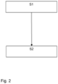
- Fig. 2 shows the chronological sequence of the method according to the invention, the method or the chronological sequence already being based on the Fig. 1 was explained in terms of apparatus.
Landscapes
- Engineering & Computer Science (AREA)
- Architecture (AREA)
- Civil Engineering (AREA)
- Structural Engineering (AREA)
- Machines For Laying And Maintaining Railways (AREA)
- Railway Tracks (AREA)
Claims (14)
- Procédé de fabrication d'un corps de voie ferrée (1), comprenant :- Application (S1) d'un liquide (9) durcissable ou épaississable sur un lit de voie (2) du corps de voie (1) formé de pierres de ballast (3), le liquide (9) étant appliqué en surface sur le lit de voie (2),- durcissement (S2) ou épaississement du liquide (9), formant ainsi une couche (13) pénétrant superficiellement dans le lit de voie (2), dans laquelle des pierres de ballast (3) se trouvant sur une surface du lit de voie (2) sont reliées entre elles,le corps de voie (1) comportant des rails (4),le liquide (9) comportant un colorant et la couche formée par le liquide durci ou épaissi étant colorée par le colorant,caractérisé en ce quele liquide (9) est appliqué de manière à ce que le liquide (9) soit appliqué sur des flancs intérieurs (10) des rails (4).
- Procédé selon la revendication 1, dans lequel la couche formée par le liquide durci ou épaissi est colorée de manière mate par le colorant.
- Procédé selon la revendication 2, dans lequel le colorant a une couleur choisie parmi le blanc, le gris ou le beige.
- Procédé selon la revendication 1 ou 2, dans lequel l'épaisseur de la couche est ≤ 15 cm, de préférence 1-10 cm, plus préférablement 1-7 cm.
- Procédé selon l'une quelconque des revendications précédentes, dans lequel la structure formée par durcissement ou épaississement du liquide (9) est dégradable par les UV, de telle sorte que, lorsque le corps de voie est disposé à l'extérieur sans être recouvert, après une période de 6 ans au plus tard après la formation de la couche (13), la structure est suffisamment dégradée pour que les ballasts (3) précédemment intégrés dans la couche puissent être détachés manuellement de la plateforme de la lit de voie (2).
- Procédé selon l'une quelconque des revendications précédentes, dans lequel le corps de voie (1) comprend des traverses, et dans lequel le liquide (9) est appliqué de telle sorte que le liquide est appliqué sur le lit de voie ferrée exposé entre les traverses et qu'aucun liquide (9) n'est appliqué sur une partie prépondérante de la surface ou sur la surface entière des traverses.
- Procédé selon l'une quelconque des revendications précédentes, dans lequel le liquide (9) est durcissable en une matière plastique, une résine synthétique ou un silicate.
- Procédé selon l'une des revendications précédentes, dans lequel le liquide (9) est expansé lors de l'application.
- Corps de voie (1), dans lequel des pierres de ballast (3) se trouvant sur une surface d'un lit de voie (2) sont intégrées dans une couche (13) qui est formée en surface dans le lit de voie (2),le corps de voie (1) présentant des rails (4),et liquide (9) durci ou épaissi, à partir duquel la couche (13) est formée avec les pierres de ballast (3), est appliqué, etle liquide (9) comprenant un colorant,caractérisé en ce quele liquide est également appliqué sur les flancs intérieurs (10) des rails (4).
- Corps de voie selon la revendication 9, dans lequel la couche (13) est colorée en blanc, en gris ou en beige par le colorant.
- Corps de voie selon la revendication 9 ou 10, dans lequel l'épaisseur de la couche est ≤ 15 cm, de préférence 1-10 cm, plus préférablement 1-7 cm.
- Corps de voie selon l'une quelconque des revendications 9 à 11, dans lequel la couche est dégradable par les UV de telle sorte que, lorsque le corps de voie est disposé à l'extérieur sans être couvert, après une période de 6 ans au plus tard après la formation de la couche (13), la couche est suffisamment décomposée pour que les pierres de ballast (3) préalablement intégrées dans la couche puissent être détachées manuellement du lit de la voie (2).
- Corps de voie selon l'une quelconque des revendications 9 à 12, dans lequel le corps de voie (1) comprend des traverses, et dans lequel la couche (13) est appliquée de telle sorte que la couche est appliquée sur un lit de voie (2) exposé entre les traverses, et qu'aucun liquide durci ou épaissi (9), à partir duquel la couche (13) est formée avec les pierres de ballast (3), n'est appliqué sur une partie prépondérante de la surface ou sur la surface entière des traverses.
- Corps de voie selon l'une quelconque des revendications 9 à 13, dans laquelle colorant est choisi parmi le blanc, le gris ou le beige.
Applications Claiming Priority (2)
| Application Number | Priority Date | Filing Date | Title |
|---|---|---|---|
| DE102019214562.0A DE102019214562A1 (de) | 2019-09-24 | 2019-09-24 | Verfahren zur Herstellung eines Gleiskörpers |
| PCT/EP2020/076736 WO2021058652A1 (fr) | 2019-09-24 | 2020-09-24 | Procédé pour produire un corps de rail et corps de rail formé au moyen de ce procédé |
Publications (3)
| Publication Number | Publication Date |
|---|---|
| EP4034708A1 EP4034708A1 (fr) | 2022-08-03 |
| EP4034708C0 EP4034708C0 (fr) | 2024-01-03 |
| EP4034708B1 true EP4034708B1 (fr) | 2024-01-03 |
Family
ID=72670690
Family Applications (1)
| Application Number | Title | Priority Date | Filing Date |
|---|---|---|---|
| EP20781461.7A Active EP4034708B1 (fr) | 2019-09-24 | 2020-09-24 | Procédé de fabrication du corps de voie ferrée et corps de voie ferrée formé par ce procédé |
Country Status (3)
| Country | Link |
|---|---|
| EP (1) | EP4034708B1 (fr) |
| DE (1) | DE102019214562A1 (fr) |
| WO (1) | WO2021058652A1 (fr) |
Families Citing this family (1)
| Publication number | Priority date | Publication date | Assignee | Title |
|---|---|---|---|---|
| DE102021211499A1 (de) * | 2021-10-12 | 2023-04-13 | Hyperion Verwaltung Gmbh | Verfahren und Vorrichtung zum Recyceln von Polyurethan-Schotter-Verbünden |
Family Cites Families (15)
| Publication number | Priority date | Publication date | Assignee | Title |
|---|---|---|---|---|
| DD86201A (fr) * | ||||
| DE2063727A1 (de) * | 1970-12-24 | 1972-08-24 | Michelfelder, Gerhard, 8000 München | Verfahren zur Stabilisierung eines Schotterbettes |
| AT337748B (de) * | 1974-01-17 | 1977-07-11 | Plasser Bahnbaumasch Franz | Vorrichtung und verfahren zum verkleben des schotters einer gleisbettung |
| JPH0657339B2 (ja) * | 1989-12-02 | 1994-08-03 | コッホ・マーモリート・ゲーエムベーハー | 多成分樹脂の塗布方法と装置およびその使用 |
| DE4023541A1 (de) * | 1990-07-25 | 1992-01-30 | Koch Marmorit Gmbh | Verfahren und vorrichtung zum auftragen von mehrkomponentenharzen |
| DE4014529A1 (de) * | 1990-05-07 | 1991-11-14 | Koch Marmorit Gmbh | Verfahren zum vergroessern des querverschiebewiderstands von eisenbahnschwellen auf einem schotterbett |
| DE4214890C2 (de) * | 1992-05-07 | 1998-07-09 | Koch Marmorit Gmbh | Verwendung eines Verfahrens zur temporären Verfestigung eines Schotterbettes |
| JPH09268503A (ja) * | 1996-03-30 | 1997-10-14 | Nippon Steel Corp | 防蝕性に優れるレール及びその製造方法 |
| DE19651755A1 (de) * | 1996-12-12 | 1998-06-18 | Claus Dieter Ihle | Verfahren zur Oberflächenstabilisierung von Schotterbetten und anderen Schüttgütern im Bahn-, Straßen- und Wegebau |
| DE10218309B4 (de) * | 2002-04-24 | 2007-01-25 | Dyckerhoff Ag | Fahrweg für Schienenfahrzeuge mit einem Schotterbett für Gleise, Verfahren zu seiner Herstellung und eine Bindemittelmischung zur Verwendung in dem Verfahren |
| DE102007057064A1 (de) * | 2007-11-27 | 2009-05-28 | Hennecke Gmbh | Verfahren zum Verfestigen eines Schotterbetts und Vorrichtung zur Durchführung des Verfahrens |
| AU2012239860A1 (en) * | 2011-04-05 | 2013-05-09 | Newstyle Nominees Pty Ltd | Rail track sleeper support |
| DE102012004720A1 (de) * | 2012-03-07 | 2013-09-12 | Frank Petrick | Verfahren und Vorrichtung zum Verfestigen von lockeren Bodenmaterialien |
| EP2910585B1 (fr) * | 2014-02-21 | 2018-07-04 | Covestro Deutschland AG | Corps de ballast et procédé de fabrication de corps de ballast |
| CH712375A1 (de) * | 2016-04-19 | 2017-10-31 | Hürlimann Bautenschutz Ag | Vorrichtung und Verfahren zum Austragen von Mehrkomponentenklebstoffen auf ein körniges Gemenge. |
-
2019
- 2019-09-24 DE DE102019214562.0A patent/DE102019214562A1/de not_active Ceased
-
2020
- 2020-09-24 WO PCT/EP2020/076736 patent/WO2021058652A1/fr not_active Ceased
- 2020-09-24 EP EP20781461.7A patent/EP4034708B1/fr active Active
Also Published As
| Publication number | Publication date |
|---|---|
| EP4034708A1 (fr) | 2022-08-03 |
| WO2021058652A1 (fr) | 2021-04-01 |
| EP4034708C0 (fr) | 2024-01-03 |
| DE102019214562A1 (de) | 2021-03-25 |
Similar Documents
| Publication | Publication Date | Title |
|---|---|---|
| DE102004006165B4 (de) | Wasserdurchlässiger Bodenbelag und Verfahren zur Herstellung eines Bodenbelags | |
| EP1982019B1 (fr) | Procédé de production d'un corps de ballast soumis à un moussage partiel pour une superstructure de voie ferroviaire | |
| DE69400615T3 (de) | Element für einen synthetischen tennisplatz und sein herstellungsverfahren | |
| DE69924777T2 (de) | Verfahren zum Herstellen eines Gleisoberbaus | |
| EP0502920B1 (fr) | Procede et dispositif d'application de resines a composants multiples et leurs utilisations | |
| DE4100581A1 (de) | Formkoerper aus vulkanisiertem altgummimaterial | |
| EP4034708B1 (fr) | Procédé de fabrication du corps de voie ferrée et corps de voie ferrée formé par ce procédé | |
| DE3821963C2 (fr) | ||
| DE19522091C2 (de) | Wasser- und gasdurchlässige Wege- und Flächenbefestigung hergestellt aus einer Mischung aus körnigen Zuschlagstoffen, Bindemitteln und faserförmigen Materialien bestehenden Mischung und Verfahren zur Herstellung dieser Flächenbefestigung | |
| WO2010060980A1 (fr) | Structure d'étanchéification d'une chaussée et son procédé de production | |
| DE2305536A1 (de) | Verfahren zum heben von gleisen und von strassenbelagsstuecken, vorrichtung zum durchfuehren dieses verfahrens und gleisschwelle | |
| DE3941142C2 (de) | Belag aus einer Steinschüttung zum Erhöhen der Schallabsorption und/oder der Reinigungsfähigkeit eines Bahngleises und Verfahren zum Herstellen desselben | |
| EP0913522A1 (fr) | Pavés de pierres moulés, liés par de la résine synthétique, méthode de production et utilisation | |
| WO2012130425A2 (fr) | Trajectoire de voie de circulation pour véhicules sur rails et support de voie de circulation pour une telle trajectoire de voie de circulation | |
| WO2009036990A1 (fr) | Dispositifs de superstructure ferroviaire | |
| DE19642025A1 (de) | Verfahren zur Herstellung einer drainagefähigen Trennschicht zwischen Kiesbettung und Fahrbahnbelag im Straßen-, Wege- und Platzbau in Verbindung mit drainagefähigen Seitenstreifen und einem seitlich abgewinkeltem Fahrbahnbelag | |
| DE3941141C2 (de) | Verfahren zum Glätten des Überganges zwischen einer weichen und einer festen Schienen-Fahrbahn | |
| DE69312746T2 (de) | Verfahren und vorrichtung zum herstellen einer strassenmarkierung | |
| DE3833720A1 (de) | Verfahren zur herstellung eines oberbaus fuer schienenbahnen | |
| DE20015289U1 (de) | Belag für flächige Betonbauwerke | |
| DE10261641A1 (de) | Verfahren zum Herstellen einer Festen Fahrbahn und Fahrweg | |
| DE19632638A1 (de) | Vorrichtung und Verfahren zur Stabilisierung bzw. Verfestigung von Schotterbetten und anderen Haufwerksgebilden und deren Anwendung | |
| EP0141772A2 (fr) | Plaque de ventilation pour l'assainissement ou le plantage d'arbres | |
| DE19632640A1 (de) | Verfahren zur Herstellung und/oder dessen Vorfertigung eines drainagefähigen Schüttgutbelages und/oder Bauelementes für den Bahn-, Straßen- und Wegebau und Hoch- u. Tiefbau | |
| EP3115520B1 (fr) | Procede de fixation ulterieure de murs éxterieurs insuffisamment ancrés d'un mur à double paroi |
Legal Events
| Date | Code | Title | Description |
|---|---|---|---|
| STAA | Information on the status of an ep patent application or granted ep patent |
Free format text: STATUS: UNKNOWN |
|
| STAA | Information on the status of an ep patent application or granted ep patent |
Free format text: STATUS: THE INTERNATIONAL PUBLICATION HAS BEEN MADE |
|
| PUAI | Public reference made under article 153(3) epc to a published international application that has entered the european phase |
Free format text: ORIGINAL CODE: 0009012 |
|
| STAA | Information on the status of an ep patent application or granted ep patent |
Free format text: STATUS: REQUEST FOR EXAMINATION WAS MADE |
|
| 17P | Request for examination filed |
Effective date: 20220413 |
|
| AK | Designated contracting states |
Kind code of ref document: A1 Designated state(s): AL AT BE BG CH CY CZ DE DK EE ES FI FR GB GR HR HU IE IS IT LI LT LU LV MC MK MT NL NO PL PT RO RS SE SI SK SM TR |
|
| DAV | Request for validation of the european patent (deleted) | ||
| DAX | Request for extension of the european patent (deleted) | ||
| GRAP | Despatch of communication of intention to grant a patent |
Free format text: ORIGINAL CODE: EPIDOSNIGR1 |
|
| STAA | Information on the status of an ep patent application or granted ep patent |
Free format text: STATUS: GRANT OF PATENT IS INTENDED |
|
| RAP1 | Party data changed (applicant data changed or rights of an application transferred) |
Owner name: HYPERION B.V. |
|
| INTG | Intention to grant announced |
Effective date: 20230214 |
|
| GRAS | Grant fee paid |
Free format text: ORIGINAL CODE: EPIDOSNIGR3 |
|
| GRAJ | Information related to disapproval of communication of intention to grant by the applicant or resumption of examination proceedings by the epo deleted |
Free format text: ORIGINAL CODE: EPIDOSDIGR1 |
|
| GRAL | Information related to payment of fee for publishing/printing deleted |
Free format text: ORIGINAL CODE: EPIDOSDIGR3 |
|
| STAA | Information on the status of an ep patent application or granted ep patent |
Free format text: STATUS: REQUEST FOR EXAMINATION WAS MADE |
|
| GRAP | Despatch of communication of intention to grant a patent |
Free format text: ORIGINAL CODE: EPIDOSNIGR1 |
|
| STAA | Information on the status of an ep patent application or granted ep patent |
Free format text: STATUS: GRANT OF PATENT IS INTENDED |
|
| INTC | Intention to grant announced (deleted) | ||
| INTG | Intention to grant announced |
Effective date: 20230713 |
|
| GRAA | (expected) grant |
Free format text: ORIGINAL CODE: 0009210 |
|
| STAA | Information on the status of an ep patent application or granted ep patent |
Free format text: STATUS: THE PATENT HAS BEEN GRANTED |
|
| AK | Designated contracting states |
Kind code of ref document: B1 Designated state(s): AL AT BE BG CH CY CZ DE DK EE ES FI FR GB GR HR HU IE IS IT LI LT LU LV MC MK MT NL NO PL PT RO RS SE SI SK SM TR |
|
| REG | Reference to a national code |
Ref country code: GB Ref legal event code: FG4D Free format text: NOT ENGLISH |
|
| REG | Reference to a national code |
Ref country code: DE Ref legal event code: R096 Ref document number: 502020006633 Country of ref document: DE |
|
| REG | Reference to a national code |
Ref country code: CH Ref legal event code: EP |
|
| REG | Reference to a national code |
Ref country code: IE Ref legal event code: FG4D Free format text: LANGUAGE OF EP DOCUMENT: GERMAN |
|
| U01 | Request for unitary effect filed |
Effective date: 20240125 |
|
| U07 | Unitary effect registered |
Designated state(s): AT BE BG DE DK EE FI FR IT LT LU LV MT NL PT SE SI Effective date: 20240206 |
|
| PG25 | Lapsed in a contracting state [announced via postgrant information from national office to epo] |
Ref country code: ES Free format text: LAPSE BECAUSE OF FAILURE TO SUBMIT A TRANSLATION OF THE DESCRIPTION OR TO PAY THE FEE WITHIN THE PRESCRIBED TIME-LIMIT Effective date: 20240103 |
|
| PG25 | Lapsed in a contracting state [announced via postgrant information from national office to epo] |
Ref country code: ES Free format text: LAPSE BECAUSE OF FAILURE TO SUBMIT A TRANSLATION OF THE DESCRIPTION OR TO PAY THE FEE WITHIN THE PRESCRIBED TIME-LIMIT Effective date: 20240103 |
|
| PG25 | Lapsed in a contracting state [announced via postgrant information from national office to epo] |
Ref country code: IS Free format text: LAPSE BECAUSE OF FAILURE TO SUBMIT A TRANSLATION OF THE DESCRIPTION OR TO PAY THE FEE WITHIN THE PRESCRIBED TIME-LIMIT Effective date: 20240503 |
|
| PG25 | Lapsed in a contracting state [announced via postgrant information from national office to epo] |
Ref country code: GR Free format text: LAPSE BECAUSE OF FAILURE TO SUBMIT A TRANSLATION OF THE DESCRIPTION OR TO PAY THE FEE WITHIN THE PRESCRIBED TIME-LIMIT Effective date: 20240404 |
|
| PG25 | Lapsed in a contracting state [announced via postgrant information from national office to epo] |
Ref country code: HR Free format text: LAPSE BECAUSE OF FAILURE TO SUBMIT A TRANSLATION OF THE DESCRIPTION OR TO PAY THE FEE WITHIN THE PRESCRIBED TIME-LIMIT Effective date: 20240103 Ref country code: RS Free format text: LAPSE BECAUSE OF FAILURE TO SUBMIT A TRANSLATION OF THE DESCRIPTION OR TO PAY THE FEE WITHIN THE PRESCRIBED TIME-LIMIT Effective date: 20240403 |
|
| PG25 | Lapsed in a contracting state [announced via postgrant information from national office to epo] |
Ref country code: CZ Free format text: LAPSE BECAUSE OF FAILURE TO SUBMIT A TRANSLATION OF THE DESCRIPTION OR TO PAY THE FEE WITHIN THE PRESCRIBED TIME-LIMIT Effective date: 20240103 |
|
| PG25 | Lapsed in a contracting state [announced via postgrant information from national office to epo] |
Ref country code: RS Free format text: LAPSE BECAUSE OF FAILURE TO SUBMIT A TRANSLATION OF THE DESCRIPTION OR TO PAY THE FEE WITHIN THE PRESCRIBED TIME-LIMIT Effective date: 20240403 Ref country code: NO Free format text: LAPSE BECAUSE OF FAILURE TO SUBMIT A TRANSLATION OF THE DESCRIPTION OR TO PAY THE FEE WITHIN THE PRESCRIBED TIME-LIMIT Effective date: 20240403 Ref country code: IS Free format text: LAPSE BECAUSE OF FAILURE TO SUBMIT A TRANSLATION OF THE DESCRIPTION OR TO PAY THE FEE WITHIN THE PRESCRIBED TIME-LIMIT Effective date: 20240503 Ref country code: HR Free format text: LAPSE BECAUSE OF FAILURE TO SUBMIT A TRANSLATION OF THE DESCRIPTION OR TO PAY THE FEE WITHIN THE PRESCRIBED TIME-LIMIT Effective date: 20240103 Ref country code: GR Free format text: LAPSE BECAUSE OF FAILURE TO SUBMIT A TRANSLATION OF THE DESCRIPTION OR TO PAY THE FEE WITHIN THE PRESCRIBED TIME-LIMIT Effective date: 20240404 Ref country code: CZ Free format text: LAPSE BECAUSE OF FAILURE TO SUBMIT A TRANSLATION OF THE DESCRIPTION OR TO PAY THE FEE WITHIN THE PRESCRIBED TIME-LIMIT Effective date: 20240103 |
|
| PG25 | Lapsed in a contracting state [announced via postgrant information from national office to epo] |
Ref country code: PL Free format text: LAPSE BECAUSE OF FAILURE TO SUBMIT A TRANSLATION OF THE DESCRIPTION OR TO PAY THE FEE WITHIN THE PRESCRIBED TIME-LIMIT Effective date: 20240103 |
|
| PG25 | Lapsed in a contracting state [announced via postgrant information from national office to epo] |
Ref country code: PL Free format text: LAPSE BECAUSE OF FAILURE TO SUBMIT A TRANSLATION OF THE DESCRIPTION OR TO PAY THE FEE WITHIN THE PRESCRIBED TIME-LIMIT Effective date: 20240103 |
|
| REG | Reference to a national code |
Ref country code: DE Ref legal event code: R097 Ref document number: 502020006633 Country of ref document: DE |
|
| PG25 | Lapsed in a contracting state [announced via postgrant information from national office to epo] |
Ref country code: SM Free format text: LAPSE BECAUSE OF FAILURE TO SUBMIT A TRANSLATION OF THE DESCRIPTION OR TO PAY THE FEE WITHIN THE PRESCRIBED TIME-LIMIT Effective date: 20240103 |
|
| PG25 | Lapsed in a contracting state [announced via postgrant information from national office to epo] |
Ref country code: SK Free format text: LAPSE BECAUSE OF FAILURE TO SUBMIT A TRANSLATION OF THE DESCRIPTION OR TO PAY THE FEE WITHIN THE PRESCRIBED TIME-LIMIT Effective date: 20240103 |
|
| PG25 | Lapsed in a contracting state [announced via postgrant information from national office to epo] |
Ref country code: SM Free format text: LAPSE BECAUSE OF FAILURE TO SUBMIT A TRANSLATION OF THE DESCRIPTION OR TO PAY THE FEE WITHIN THE PRESCRIBED TIME-LIMIT Effective date: 20240103 Ref country code: SK Free format text: LAPSE BECAUSE OF FAILURE TO SUBMIT A TRANSLATION OF THE DESCRIPTION OR TO PAY THE FEE WITHIN THE PRESCRIBED TIME-LIMIT Effective date: 20240103 Ref country code: RO Free format text: LAPSE BECAUSE OF FAILURE TO SUBMIT A TRANSLATION OF THE DESCRIPTION OR TO PAY THE FEE WITHIN THE PRESCRIBED TIME-LIMIT Effective date: 20240103 |
|
| PLBE | No opposition filed within time limit |
Free format text: ORIGINAL CODE: 0009261 |
|
| STAA | Information on the status of an ep patent application or granted ep patent |
Free format text: STATUS: NO OPPOSITION FILED WITHIN TIME LIMIT |
|
| 26N | No opposition filed |
Effective date: 20241007 |
|
| U21 | Renewal fee for the european patent with unitary effect paid with additional fee |
Year of fee payment: 5 Effective date: 20241126 |
|
| PG25 | Lapsed in a contracting state [announced via postgrant information from national office to epo] |
Ref country code: MC Free format text: LAPSE BECAUSE OF FAILURE TO SUBMIT A TRANSLATION OF THE DESCRIPTION OR TO PAY THE FEE WITHIN THE PRESCRIBED TIME-LIMIT Effective date: 20240103 |
|
| REG | Reference to a national code |
Ref country code: CH Ref legal event code: PL |
|
| GBPC | Gb: european patent ceased through non-payment of renewal fee |
Effective date: 20240924 |
|
| PG25 | Lapsed in a contracting state [announced via postgrant information from national office to epo] |
Ref country code: GB Free format text: LAPSE BECAUSE OF NON-PAYMENT OF DUE FEES Effective date: 20240924 |
|
| PG25 | Lapsed in a contracting state [announced via postgrant information from national office to epo] |
Ref country code: CH Free format text: LAPSE BECAUSE OF NON-PAYMENT OF DUE FEES Effective date: 20240930 |
|
| PG25 | Lapsed in a contracting state [announced via postgrant information from national office to epo] |
Ref country code: IE Free format text: LAPSE BECAUSE OF NON-PAYMENT OF DUE FEES Effective date: 20240924 |
|
| U20 | Renewal fee for the european patent with unitary effect paid |
Year of fee payment: 6 Effective date: 20250715 |
|
| U1K | Transfer of rights of the unitary patent after the registration of the unitary effect |
Owner name: HYPERION VERWALTUNG GMBH; DE |
|
| PG25 | Lapsed in a contracting state [announced via postgrant information from national office to epo] |
Ref country code: CY Free format text: LAPSE BECAUSE OF FAILURE TO SUBMIT A TRANSLATION OF THE DESCRIPTION OR TO PAY THE FEE WITHIN THE PRESCRIBED TIME-LIMIT; INVALID AB INITIO Effective date: 20200924 |
|
| PG25 | Lapsed in a contracting state [announced via postgrant information from national office to epo] |
Ref country code: HU Free format text: LAPSE BECAUSE OF FAILURE TO SUBMIT A TRANSLATION OF THE DESCRIPTION OR TO PAY THE FEE WITHIN THE PRESCRIBED TIME-LIMIT; INVALID AB INITIO Effective date: 20200924 |