EP4035482B1 - Procédé et appareil pour la priorité de transmission dans un système de communication sans fil - Google Patents
Procédé et appareil pour la priorité de transmission dans un système de communication sans fil Download PDFInfo
- Publication number
- EP4035482B1 EP4035482B1 EP20880797.4A EP20880797A EP4035482B1 EP 4035482 B1 EP4035482 B1 EP 4035482B1 EP 20880797 A EP20880797 A EP 20880797A EP 4035482 B1 EP4035482 B1 EP 4035482B1
- Authority
- EP
- European Patent Office
- Prior art keywords
- bsr
- transmission
- sidelink
- mac
- network
- Prior art date
- Legal status (The legal status is an assumption and is not a legal conclusion. Google has not performed a legal analysis and makes no representation as to the accuracy of the status listed.)
- Active
Links
Images




Classifications
-
- H—ELECTRICITY
- H04—ELECTRIC COMMUNICATION TECHNIQUE
- H04W—WIRELESS COMMUNICATION NETWORKS
- H04W28/00—Network traffic management; Network resource management
- H04W28/02—Traffic management, e.g. flow control or congestion control
- H04W28/0278—Traffic management, e.g. flow control or congestion control using buffer status reports
-
- H—ELECTRICITY
- H04—ELECTRIC COMMUNICATION TECHNIQUE
- H04W—WIRELESS COMMUNICATION NETWORKS
- H04W72/00—Local resource management
- H04W72/20—Control channels or signalling for resource management
- H04W72/21—Control channels or signalling for resource management in the uplink direction of a wireless link, i.e. towards the network
-
- H—ELECTRICITY
- H04—ELECTRIC COMMUNICATION TECHNIQUE
- H04W—WIRELESS COMMUNICATION NETWORKS
- H04W72/00—Local resource management
- H04W72/50—Allocation or scheduling criteria for wireless resources
- H04W72/56—Allocation or scheduling criteria for wireless resources based on priority criteria
- H04W72/566—Allocation or scheduling criteria for wireless resources based on priority criteria of the information or information source or recipient
- H04W72/569—Allocation or scheduling criteria for wireless resources based on priority criteria of the information or information source or recipient of the traffic information
-
- H—ELECTRICITY
- H04—ELECTRIC COMMUNICATION TECHNIQUE
- H04W—WIRELESS COMMUNICATION NETWORKS
- H04W76/00—Connection management
- H04W76/10—Connection setup
- H04W76/14—Direct-mode setup
-
- H—ELECTRICITY
- H04—ELECTRIC COMMUNICATION TECHNIQUE
- H04W—WIRELESS COMMUNICATION NETWORKS
- H04W92/00—Interfaces specially adapted for wireless communication networks
- H04W92/16—Interfaces between hierarchically similar devices
- H04W92/18—Interfaces between hierarchically similar devices between terminal devices
Definitions
- the present disclosure relates to transmission prioritization in wireless communications.
- 3rd generation partnership project (3GPP) long-term evolution (LTE) is a technology for enabling high-speed packet communications.
- 3GPP 3rd generation partnership project
- LTE long-term evolution
- Many schemes have been proposed for the LTE objective including those that aim to reduce user and provider costs, improve service quality, and expand and improve coverage and system capacity.
- the 3GPP LTE requires reduced cost per bit, increased service availability, flexible use of a frequency band, a simple structure, an open interface, and adequate power consumption of a terminal as an upper-level requirement.
- ITU international telecommunication union
- NR new radio
- 3GPP has to identify and develop the technology components needed for successfully standardizing the new RAT timely satisfying both the urgent market needs, and the more long-term requirements set forth by the ITU radio communication sector (ITU-R) international mobile telecommunications (IMT)-2020 process.
- ITU-R ITU radio communication sector
- IMT international mobile telecommunications
- the NR should be able to use any spectrum band ranging at least up to 100 GHz that may be made available for wireless communications even in a more distant future.
- the NR targets a single technical framework addressing all usage scenarios, requirements and deployment scenarios including enhanced mobile broadband (eMBB), massive machine-type-communications (mMTC), ultra-reliable and low latency communications (URLLC), etc.
- eMBB enhanced mobile broadband
- mMTC massive machine-type-communications
- URLLC ultra-reliable and low latency communications
- the NR shall be inherently forward compatible.
- a communication device may perform various types of transmissions. However, due to limited resources, a certain type of transmission may collide with other types of transmissions. In this case, one transmission may be prioritized than the other transmission.
- An aspect of the present disclosure is to provide a method, a wireless device and a computer-readable storage medium for a prioritization between a BSR and sidelink BSR in a wireless communication system.
- the present disclosure can have various advantageous effects.
- a UE performing UL and SL transmissions by using priorities of UL and SL can properly prioritize one of UL and SL transmissions for transmissions of packets considering service characteristics and requirements.
- the present disclosure is beneficial when different transmissions collide (e.g. between uplink and sidelink or between different RATs).
- the present disclosure is beneficial in that the system can provide proper prioritization of different types of transmissions in collision for data transmissions for a UE performing multiple transmissions.
- SL-BSR may have a higher priority than UL-BSR so that the SL-BSR with the higher priority can be reported preferentially than the UL-BSR.
- the technical features described below may be used by a communication standard by the 3rd generation partnership project (3GPP) standardization organization, a communication standard by the institute of electrical and electronics engineers (IEEE), etc.
- the communication standards by the 3GPP standardization organization include long-term evolution (LTE) and/or evolution of LTE systems.
- LTE long-term evolution
- LTE-A LTE-advanced
- LTE-A Pro LTE-A Pro
- NR 5G new radio
- the communication standard by the IEEE standardization organization includes a wireless local area network (WLAN) system such as IEEE 802.11a/b/g/n/ac/ax.
- WLAN wireless local area network
- the above system uses various multiple access technologies such as orthogonal frequency division multiple access (OFDMA) and/or single carrier frequency division multiple access (SC-FDMA) for downlink (DL) and/or uplink (UL).
- OFDMA orthogonal frequency division multiple access
- SC-FDMA single carrier frequency division multiple access
- OFDMA and SC-FDMA may be used for DL and/or UL.
- the radio communication technologies implemented in the wireless devices in the present disclosure may include narrowband internet-of-things (NB-IoT) technology for low-power communication as well as LTE, NR and 6G.
- NB-IoT technology may be an example of low power wide area network (LPWAN) technology, may be implemented in specifications such as LTE Cat NB1 and/or LTE Cat NB2, and may not be limited to the above-mentioned names.
- LPWAN low power wide area network
- the radio communication technologies implemented in the wireless devices in the present disclosure may communicate based on LTE-M technology.
- LTE-M technology may be an example of LPWAN technology and be called by various names such as enhanced machine type communication (eMTC).
- eMTC enhanced machine type communication
- LTE-M technology may be implemented in at least one of the various specifications, such as 1) LTE Cat 0, 2) LTE Cat M1, 3) LTE Cat M2, 4) LTE non-bandwidth limited (non-BL), 5) LTE-MTC, 6) LTE Machine Type Communication, and/or 7) LTE M, and may not be limited to the above-mentioned names.
- the radio communication technologies implemented in the wireless devices in the present disclosure may include at least one of ZigBee, Bluetooth, and/or LPWAN which take into account low-power communication, and may not be limited to the above-mentioned names.
- ZigBee technology may generate personal area networks (PANs) associated with small/low-power digital communication based on various specifications such as IEEE 802.15.4 and may be called various names.
- PANs personal area networks
- a or B may mean “only A”, “only B”, or “both A and B”.
- a or B in the present disclosure may be interpreted as “A and/or B”.
- A, B or C in the present disclosure may mean “only A”, “only B”, “only C”, or "any combination of A, B and C”.
- slash (/) or comma (,) may mean “and/or”.
- A/B may mean “A and/or B”.
- A/B may mean "only A”, “only B”, or “both A and B”.
- A, B, C may mean "A, B or C”.
- At least one of A and B may mean “only A”, “only B” or “both A and B”.
- the expression “at least one of A or B” or “at least one of A and/or B” in the present disclosure may be interpreted as same as “at least one of A and B”.
- At least one of A, B and C may mean “only A”, “only B”, “only C”, or “any combination of A, B and C”.
- at least one of A, B or C or “at least one of A, B and/or C” may mean “at least one of A, B and C”.
- parentheses used in the present disclosure may mean “for example”.
- control information PDCCH
- PDCCH PDCCH
- PDCCH PDCCH
- Logical channel prioritization may comprise allocating resources to logical channels according to a priority of the logical channels. For example, according to LCP, resources of UL grant and/or SL grant may be allocated to logical channels in a decreasing order of a priority of the logical channels. A logical channels to which resources of SL grant and/or UL grant are allocated may be included in MAC PDU. Therefore, according to LCP, logical channels may be included in the MAC PDU in a decreasing order of a priority of the logical channels.
- Priority value of A is higher than that of B means that priority and/or priority level of A is lower than that of B.
- Priority value of A is lower than that of B means that priority and/or priority level of A is higher than that of B.
- RAN radio access network
- the terms 'cell quality', 'signal strength', 'signal quality', 'channel state', 'channel quality', ' channel state/reference signal received power (RSRP)' and ' reference signal received quality (RSRQ)' may be used interchangeably.
- FIG. 1 illustrates an example of a communication system to which implementations of the present disclosure is applied.
- Three main requirement categories for 5G include (1) a category of enhanced mobile broadband (eMBB), (2) a category of massive machine type communication (mMTC), and (3) a category of ultra-reliable and low latency communications (URLLC).
- eMBB enhanced mobile broadband
- mMTC massive machine type communication
- URLLC ultra-reliable and low latency communications
- Partial use cases may require a plurality of categories for optimization and other use cases may focus only upon one key performance indicator (KPI).
- KPI key performance indicator
- eMBB far surpasses basic mobile Internet access and covers abundant bidirectional work and media and entertainment applications in cloud and augmented reality.
- Data is one of 5G core motive forces and, in a 5G era, a dedicated voice service may not be provided for the first time.
- voice will be simply processed as an application program using data connection provided by a communication system.
- Main causes for increased traffic volume are due to an increase in the size of content and an increase in the number of applications requiring high data transmission rate.
- a streaming service (of audio and video), conversational video, and mobile Internet access will be more widely used as more devices are connected to the Internet.
- Cloud storage and applications are rapidly increasing in a mobile communication platform and may be applied to both work and entertainment.
- the cloud storage is a special use case which accelerates growth of uplink data transmission rate.
- 5G is also used for remote work of cloud. When a tactile interface is used, 5G demands much lower end-to-end latency to maintain user good experience.
- Entertainment for example, cloud gaming and video streaming, is another core element which increases demand for mobile broadband capability. Entertainment is essential for a smartphone and a tablet in any place including high mobility environments such as a train, a vehicle, and an airplane.
- Other use cases are augmented reality for entertainment and information search. In this case, the augmented reality requires very low latency and instantaneous data volume.
- one of the most expected 5G use cases relates a function capable of smoothly connecting embedded sensors in all fields, i.e., mMTC. It is expected that the number of potential IoT devices will reach 204 hundred million up to the year of 2020.
- An industrial IoT is one of categories of performing a main role enabling a smart city, asset tracking, smart utility, agriculture, and security infrastructure through 5G.
- URLLC includes a new service that will change industry through remote control of main infrastructure and an ultra-reliable/available low-latency link such as a self-driving vehicle.
- a level of reliability and latency is essential to control a smart grid, automatize industry, achieve robotics, and control and adjust a drone.
- 5G is a means of providing streaming evaluated as a few hundred megabits per second to gigabits per second and may complement fiber-to-the-home (FTTH) and cable-based broadband (or DOCSIS). Such fast speed is needed to deliver TV in resolution of 4K or more (6K, 8K, and more), as well as virtual reality and augmented reality.
- Virtual reality (VR) and augmented reality (AR) applications include almost immersive sports games.
- a specific application program may require a special network configuration. For example, for VR games, gaming companies need to incorporate a core server into an edge network server of a network operator in order to minimize latency.
- Automotive is expected to be a new important motivated force in 5G together with many use cases for mobile communication for vehicles. For example, entertainment for passengers requires high simultaneous capacity and mobile broadband with high mobility. This is because future users continue to expect connection of high quality regardless of their locations and speeds.
- Another use case of an automotive field is an AR dashboard.
- the AR dashboard causes a driver to identify an object in the dark in addition to an object seen from a front window and displays a distance from the object and a movement of the object by overlapping information talking to the driver.
- a wireless module enables communication between vehicles, information exchange between a vehicle and supporting infrastructure, and information exchange between a vehicle and other connected devices (e.g., devices accompanied by a pedestrian).
- a safety system guides alternative courses of a behavior so that a driver may drive more safely drive, thereby lowering the danger of an accident.
- the next stage will be a remotely controlled or self-driven vehicle. This requires very high reliability and very fast communication between different self-driven vehicles and between a vehicle and infrastructure. In the future, a self-driven vehicle will perform all driving activities and a driver will focus only upon abnormal traffic that the vehicle cannot identify.
- Technical requirements of a self-driven vehicle demand ultra-low latency and ultra-high reliability so that traffic safety is increased to a level that cannot be achieved by human being.
- a smart city and a smart home/building mentioned as a smart society will be embedded in a high-density wireless sensor network.
- a distributed network of an intelligent sensor will identify conditions for costs and energy-efficient maintenance of a city or a home. Similar configurations may be performed for respective households. All of temperature sensors, window and heating controllers, burglar alarms, and home appliances are wirelessly connected. Many of these sensors are typically low in data transmission rate, power, and cost. However, real-time HD video may be demanded by a specific type of device to perform monitoring.
- the smart grid collects information and connects the sensors to each other using digital information and communication technology so as to act according to the collected information. Since this information may include behaviors of a supply company and a consumer, the smart grid may improve distribution of fuels such as electricity by a method having efficiency, reliability, economic feasibility, production sustainability, and automation.
- the smart grid may also be regarded as another sensor network having low latency.
- Mission critical application is one of 5G use scenarios.
- a health part contains many application programs capable of enjoying benefit of mobile communication.
- a communication system may support remote treatment that provides clinical treatment in a faraway place. Remote treatment may aid in reducing a barrier against distance and improve access to medical services that cannot be continuously available in a faraway rural area. Remote treatment is also used to perform important treatment and save lives in an emergency situation.
- the wireless sensor network based on mobile communication may provide remote monitoring and sensors for parameters such as heart rate and blood pressure.
- Wireless and mobile communication gradually becomes important in the field of an industrial application.
- Wiring is high in installation and maintenance cost. Therefore, a possibility of replacing a cable with reconstructible wireless links is an attractive opportunity in many industrial fields.
- it is necessary for wireless connection to be established with latency, reliability, and capacity similar to those of the cable and management of wireless connection needs to be simplified. Low latency and a very low error probability are new requirements when connection to 5G is needed.
- Logistics and freight tracking are important use cases for mobile communication that enables inventory and package tracking anywhere using a location-based information system.
- the use cases of logistics and freight typically demand low data rate but require location information with a wide range and reliability.
- the communication system 1 includes wireless devices, base stations (BSs), and a network.
- FIG. 1 illustrates a 5G network as an example of the network of the communication system 1, the implementations of the present disclosure are not limited to the 5G system, and can be applied to the future communication system beyond the 5G system.
- the BSs and the network may be implemented as wireless devices and a specific wireless device 200a may operate as a BS/network node with respect to other wireless devices.
- the wireless devices represent devices performing communication using radio access technology (RAT) (e.g., 5G New RAT (NR)) or Long-Term Evolution (LTE)) and may be referred to as communication/radio/5G devices.
- RAT radio access technology
- the wireless devices may include, without being limited to, a robot 100a, vehicles 100b-1 and 100b-2, an extended Reality (XR) device 100c, a hand-held device 100d, a home appliance 100e, an Internet of Things (IoT) device 100f, and an Artificial Intelligence (AI) device/ server 400.
- the vehicles may include a vehicle having a wireless communication function, an autonomous driving vehicle, and a vehicle capable of performing communication between vehicles.
- the vehicles may include an Unmanned Aerial Vehicle (UAV) (e.g., a drone).
- UAV Unmanned Aerial Vehicle
- the XR device may include an Augmented Reality (AR)/Virtual Reality (VR)/Mixed Reality (MR) device and may be implemented in the form of a Head-Mounted Device (HMD), a Head-Up Display (HUD) mounted in a vehicle, a television, a smartphone, a computer, a wearable device, a home appliance device, a digital signage, a vehicle, a robot, etc.
- the hand-held device may include a smartphone, a smartpad, a wearable device (e.g., a smartwatch or a smartglasses), and a computer (e.g., a notebook).
- the home appliance may include a TV, a refrigerator, and a washing machine.
- the IoT device may include a sensor and a smartmeter.
- the wireless devices 100a to 100f may be called user equipments (UEs).
- a user equipment (UE) may include, for example, a cellular phone, a smartphone, a laptop computer, a digital broadcast terminal, a personal digital assistant (PDA), a portable multimedia player (PMP), a navigation system, a slate personal computer (PC), a tablet PC, an ultrabook, a vehicle, a vehicle having an autonomous traveling function, a connected car, an unmanned aerial vehicle (UAV), an artificial intelligence (AI) module, a robot, an augmented reality (AR) device, a virtual reality (VR) device, a mixed reality (MR) device, a hologram device, a public safety device, an MTC device, an IoT device, a medical device, a FinTech device (or a financial device), a security device, a weather/environment device, a device related to a 5G service, or a device related to a fourth industrial revolution field.
- PDA personal digital assistant
- PMP portable multimedia player
- PC
- the unmanned aerial vehicle may be, for example, an aircraft aviated by a wireless control signal without a human being onboard.
- the VR device may include, for example, a device for implementing an object or a background of the virtual world.
- the AR device may include, for example, a device implemented by connecting an object or a background of the virtual world to an object or a background of the real world.
- the MR device may include, for example, a device implemented by merging an object or a background of the virtual world into an object or a background of the real world.
- the hologram device may include, for example, a device for implementing a stereoscopic image of 360 degrees by recording and reproducing stereoscopic information, using an interference phenomenon of light generated when two laser lights called holography meet.
- the public safety device may include, for example, an image relay device or an image device that is wearable on the body of a user.
- the MTC device and the IoT device may be, for example, devices that do not require direct human intervention or manipulation.
- the MTC device and the IoT device may include smartmeters, vending machines, thermometers, smartbulbs, door locks, or various sensors.
- the medical device may be, for example, a device used for the purpose of diagnosing, treating, relieving, curing, or preventing disease.
- the medical device may be a device used for the purpose of diagnosing, treating, relieving, or correcting injury or impairment.
- the medical device may be a device used for the purpose of inspecting, replacing, or modifying a structure or a function.
- the medical device may be a device used for the purpose of adjusting pregnancy.
- the medical device may include a device for treatment, a device for operation, a device for (in vitro) diagnosis, a hearing aid, or a device for procedure.
- the security device may be, for example, a device installed to prevent a danger that may arise and to maintain safety.
- the security device may be a camera, a CCTV, a recorder, or a black box.
- the FinTech device may be, for example, a device capable of providing a financial service such as mobile payment.
- the FinTech device may include a payment device or a point of sales (POS) system.
- the weather/environment device may include, for example, a device for monitoring or predicting a weather/environment.
- the wireless devices 100a to 100f may be connected to the network 300 via the BSs 200.
- An AI technology may be applied to the wireless devices 100a to 100f and the wireless devices 100a to 100f may be connected to the AI server 400 via the network 300.
- the network 300 may be configured using a 3G network, a 4G (e.g., LTE) network, a 5G (e.g., NR) network, and a beyond-5G network.
- the wireless devices 100a to 100f may communicate with each other through the BSs 200/network 300, the wireless devices 100a to 100f may perform direct communication (e.g., sidelink communication) with each other without passing through the BSs/network.
- the vehicles 100b-1 and 100b-2 may perform direct communication (e.g.
- V2V Vehicle-to-Vehicle
- V2X Vehicle-to-everything
- Wireless communication/connections 150a and 150b may be established between the wireless devices 100a to 100f/BS 200-BS 200.
- the wireless communication/connections may be established through various RATs (e.g., 5G NR) such as uplink! downlink communication 150a and sidelink communication 150b (or D2D communication).
- the wireless devices and the BSs/the wireless devices may transmit/receive radio signals to/from each other through the wireless communication/connections 150a and 150b.
- the wireless communication/connections 150a and 150b may transmit/receive signals through various physical channels.
- various configuration information configuring processes various signal processing processes (e.g., channel encoding/decoding, modulation/demodulation, and resource mapping/demapping), and resource allocating processes, for transmitting/receiving radio signals, may be performed based on the various proposals of the present disclosure.
- various signal processing processes e.g., channel encoding/decoding, modulation/demodulation, and resource mapping/demapping
- resource allocating processes for transmitting/receiving radio signals
- NR supports multiple numerology (or, subcarrier spacing (SCS)) to support various 5G services. For example, when the SCS is 15 kHz, wide area in traditional cellular bands may be supported. When the SCS is 30 kHz/60 kHz, dense-urban, lower latency and wider carrier bandwidth may be supported. When the SCS is 60 kHz or higher, a bandwidth greater than 24.25 GHz may be supported to overcome phase noise.
- SCS subcarrier spacing
- the NR frequency band may be defined as two types of frequency range, i.e., FR1 and FR2.
- the numerical value of the frequency range may be changed.
- the frequency ranges of the two types may be as shown in Table 1 below.
- FR1 may mean "sub 6 GHz range”
- FR2 may mean "above 6 GHz range”
- mmW millimeter wave
- FR1 may include a frequency band of 410MHz to 7125MHz as shown in Table 2 below. That is, FR1 may include a frequency band of 6GHz (or 5850, 5900, 5925 MHz, etc.) or more. For example, a frequency band of 6 GHz (or 5850, 5900, 5925 MHz, etc.) or more included in FR1 may include an unlicensed band. Unlicensed bands may be used for a variety of purposes, for example for communication for vehicles (e.g., autonomous driving). [Table 2] Frequency Range designation Corresponding frequency range Subcarrier Spacing FR1 410MHz - 7125MHz 15, 30, 60kHz FR2 24250MHz - 52600MHz 60, 120, 240kHz
- FIG. 2 shows an example of a wireless communication system to which the technical features of the present disclosure can be applied.
- the wireless communication system may include a first device 210 and a second device 220.
- the first device 210 includes a base station, a network node, a transmitting UE, a receiving UE, a wireless device, a wireless communication device, a vehicle, a vehicle equipped with an autonomous driving function, a connected car, a drone, an unmanned aerial vehicle (UAV), an artificial intelligence (AI) module, a robot, an AR device, a VR device, a mixed reality (MR) device, a hologram device, a public safety device, an MTC device, an IoT device, a medical device, a fin-tech device (or, a financial device), a security device, a climate/environmental device, a device related to 5G services, or a device related to the fourth industrial revolution.
- UAV unmanned aerial vehicle
- AI artificial intelligence
- MR mixed reality
- hologram device a public safety device
- MTC device an IoT device
- medical device a fin-tech device (or, a financial device)
- a security device a climate/environmental device, a device
- the second device 220 includes a base station, a network node, a transmitting UE, a receiving UE, a wireless device, a wireless communication device, a vehicle, a vehicle equipped with an autonomous driving function, a connected car, a drone, a UAV, an AI module, a robot, an AR device, a VR device, an MR device, a hologram device, a public safety device, an MTC device, an IoT device, a medical device, a fin-tech device (or, a financial device), a security device, a climate/environmental device, a device related to 5G services, or a device related to the fourth industrial revolution.
- the UE may include a mobile phone, a smart phone, a laptop computer, a digital broadcasting terminal, a personal digital assistant (PDA), a portable multimedia player (PMP), a navigation device, a slate personal computer (PC), a tablet PC, an ultrabook, a wearable device (e.g. a smartwatch, a smart glass, a head mounted display (HMD)) .
- the HMD may be a display device worn on the head.
- the HMD may be used to implement AR, VR and/or MR.
- the drone may be a flying object that is flying by a radio control signal without a person boarding it.
- the VR device may include a device that implements an object or background in the virtual world.
- the AR device may include a device that implements connection of an object and/or a background of a virtual world to an object and/or a background of the real world.
- the MR device may include a device that implements fusion of an object and/or a background of a virtual world to an object and/or a background of the real world.
- the hologram device may include a device that implements a 360-degree stereoscopic image by recording and playing stereoscopic information by utilizing a phenomenon of interference of light generated by the two laser lights meeting with each other, called holography.
- the public safety device may include a video relay device or a video device that can be worn by the user's body.
- the MTC device and the IoT device may be a device that do not require direct human intervention or manipulation.
- the MTC device and the IoT device may include a smart meter, a vending machine, a thermometer, a smart bulb, a door lock and/or various sensors.
- the security device may include a camera, a closed-circuit TV (CCTV), a recorder, or a black box.
- the fin-tech device may be a device capable of providing financial services such as mobile payment.
- the fin-tech device may include a payment device or a point of sales (POS).
- the climate/environmental device may include a device for monitoring or predicting the climate/environment.
- the first device 210 may include at least one or more processors, such as a processor 211, at least one memory, such as a memory 212, and at least one transceiver, such as a transceiver 213.
- the processor 211 may perform the functions, procedures, and/or methods of the first device described throughout the disclosure.
- the processor 211 may perform one or more protocols. For example, the processor 211 may perform one or more layers of the air interface protocol.
- the memory 212 is connected to the processor 211 and may store various types of information and/or instructions.
- the transceiver 213 is connected to the processor 211 and may be controlled by the processor 211 to transmit and receive wireless signals.
- the second device 220 may include at least one or more processors, such as a processor 221, at least one memory, such as a memory 222, and at least one transceiver, such as a transceiver 223.
- the processor 221 may perform the functions, procedures, and/or methods of the second device 220 described throughout the disclosure.
- the processor 221 may perform one or more protocols. For example, the processor 221 may perform one or more layers of the air interface protocol.
- the memory 222 is connected to the processor 221 and may store various types of information and/or instructions.
- the transceiver 223 is connected to the processor 221 and may be controlled by the processor 221 to transmit and receive wireless signals.
- the memory 212, 222 may be connected internally or externally to the processor 211, 212, or may be connected to other processors via a variety of technologies such as wired or wireless connections.
- the first device 210 and/or the second device 220 may have more than one antenna.
- antenna 214 and/or antenna 224 may be configured to transmit and receive wireless signals.
- FIG. 3 shows a system architecture based on an evolved-UMTS terrestrial radio access network (E-UTRAN).
- E-UTRAN evolved-UMTS terrestrial radio access network
- the aforementioned LTE is a part of an evolved-UTMS (e-UMTS) using the E-UTRAN.
- e-UMTS evolved-UTMS
- the wireless communication system includes one or more user equipment (UE) 310, an E-UTRAN and an evolved packet core (EPC).
- the UE 310 refers to a communication equipment carried by a user.
- the UE 310 may be fixed or mobile.
- the UE 310 may be referred to as another terminology, such as a mobile station (MS), a user terminal (UT), a subscriber station (SS), a wireless device, etc.
- MS mobile station
- UT user terminal
- SS subscriber station
- wireless device etc.
- the E-UTRAN consists of one or more evolved NodeB (eNB) 320.
- the eNB 320 provides the E-UTRA user plane and control plane protocol terminations towards the UE 10.
- the eNB 320 is generally a fixed station that communicates with the UE 310.
- the eNB 320 hosts the functions, such as inter-cell radio resource management (RRM), radio bearer (RB) control, connection mobility control, radio admission control, measurement configuration/provision, dynamic resource allocation (scheduler), etc.
- RRM inter-cell radio resource management
- RB radio bearer
- connection mobility control such as connection mobility control
- radio admission control such as measurement configuration/provision
- the eNB 320 may be referred to as another terminology, such as a base station (BS), a base transceiver system (BTS), an access point (AP), etc.
- BS base station
- BTS base transceiver system
- AP access point
- a downlink (DL) denotes communication from the eNB 320 to the UE 310.
- An uplink (UL) denotes communication from the UE 310 to the eNB 320.
- a sidelink (SL) denotes communication between the UEs 310.
- a transmitter may be a part of the eNB 320, and a receiver may be a part of the UE 310.
- the transmitter may be a part of the UE 310, and the receiver may be a part of the eNB 320.
- the transmitter and receiver may be a part of the UE 310.
- the EPC includes a mobility management entity (MME), a serving gateway (S-GW) and a packet data network (PDN) gateway (P-GW).
- MME hosts the functions, such as non-access stratum (NAS) security, idle state mobility handling, evolved packet system (EPS) bearer control, etc.
- NAS non-access stratum
- EPS evolved packet system
- the S-GW hosts the functions, such as mobility anchoring, etc.
- the S-GW is a gateway having an E-UTRAN as an endpoint.
- MME/S-GW 330 will be referred to herein simply as a "gateway," but it is understood that this entity includes both the MME and S-GW.
- the P-GW hosts the functions, such as UE Internet protocol (IP) address allocation, packet filtering, etc.
- IP Internet protocol
- the P-GW is a gateway having a PDN as an endpoint.
- the P-GW is connected to an external network.
- the UE 310 is connected to the eNB 320 by means of the Uu interface.
- the UEs 310 are interconnected with each other by means of the PC5 interface.
- the eNBs 320 are interconnected with each other by means of the X2 interface.
- the eNBs 320 are also connected by means of the S1 interface to the EPC, more specifically to the MME by means of the S1-MME interface and to the S-GW by means of the S1-U interface.
- the S1 interface supports a many-to-many relation between MMEs / S-GWs and eNBs.
- FIG. 4 shows another example of a wireless communication system to which the technical features of the present disclosure can be applied.
- FIG. 4 shows a system architecture based on a 5G NR.
- the entity used in the 5G NR (hereinafter, simply referred to as "NR") may absorb some or all of the functions of the entities introduced in FIG. 3 (e.g. eNB, MME, S-GW).
- the entity used in the NR may be identified by the name "NG” for distinction from the LTE/LTE-A.
- the wireless communication system includes one or more UE 410, a next-generation RAN (NG-RAN) and a 5th generation core network (5GC).
- the NG-RAN consists of at least one NG-RAN node.
- the NG-RAN node is an entity corresponding to the eNB 320 shown in FIG. 3 .
- the NG-RAN node consists of at least one gNB 421 and/or at least one ng-eNB 422.
- the gNB 421 provides NR user plane and control plane protocol terminations towards the UE 410.
- the ng-eNB 422 provides E-UTRA user plane and control plane protocol terminations towards the UE 410.
- the 5GC includes an access and mobility management function (AMF), a user plane function (UPF) and a session management function (SMF).
- AMF hosts the functions, such as NAS security, idle state mobility handling, etc.
- the AMF is an entity including the functions of the conventional MME.
- the UPF hosts the functions, such as mobility anchoring, protocol data unit (PDU) handling.
- PDU protocol data unit
- the UPF an entity including the functions of the conventional S-GW.
- the SMF hosts the functions, such as UE IP address allocation, PDU session control.
- the gNBs 421 and ng-eNBs 422 are interconnected with each other by means of the Xn interface.
- the gNBs 421 and ng-eNBs 422 are also connected by means of the NG interfaces to the 5GC, more specifically to the AMF by means of the NG-C interface and to the UPF by means of the NG-U interface.
- layers of a radio interface protocol between the UE and the network may be classified into a first layer (L1), a second layer (L2), and a third layer (L3) based on the lower three layers of the open system interconnection (OSI) model that is well-known in the communication system.
- OSI open system interconnection
- FIG. 5 shows a block diagram of a user plane protocol stack to which the technical features of the present disclosure can be applied.
- FIG. 6 shows a block diagram of a control plane protocol stack to which the technical features of the present disclosure can be applied.
- the user/control plane protocol stacks shown in FIG. 5 and FIG. 6 are used in NR. However, user/control plane protocol stacks shown in FIG. 5 and FIG. 6 may be used in LTE/LTE-A without loss of generality, by replacing gNB/AMF with eNB/MME.
- the PHY layer offers information transfer services to media access control (MAC) sublayer and higher layers.
- the PHY layer offers to the MAC sublayer transport channels. Data between the MAC sublayer and the PHY layer is transferred via the transport channels.
- MAC media access control
- the MAC sublayer belongs to L2.
- the main services and functions of the MAC sublayer include mapping between logical channels and transport channels, multiplexing/de-multiplexing of MAC service data units (SDUs) belonging to one or different logical channels into/from transport blocks (TB) delivered to/from the physical layer on transport channels, scheduling information reporting, error correction through hybrid automatic repeat request (HARQ), priority handling between UEs by means of dynamic scheduling, priority handling between logical channels of one UE by means of logical channel prioritization (LCP), etc.
- the MAC sublayer offers to the radio link control (RLC) sublayer logical channels.
- RLC radio link control
- the RLC sublayer belong to L2.
- the RLC sublayer supports three transmission modes, i.e. transparent mode (TM), unacknowledged mode (UM), and acknowledged mode (AM), in order to guarantee various quality of services (QoS) required by radio bearers.
- TM transparent mode
- UM unacknowledged mode
- AM acknowledged mode
- the main services and functions of the RLC sublayer depend on the transmission mode.
- the RLC sublayer provides transfer of upper layer PDUs for all three modes, but provides error correction through ARQ for AM only.
- LTE/LTE-A the RLC sublayer provides concatenation, segmentation and reassembly of RLC SDUs (only for UM and AM data transfer) and re-segmentation of RLC data PDUs (only for AM data transfer).
- the RLC sublayer provides segmentation (only for AM and UM) and re-segmentation (only for AM) of RLC SDUs and reassembly of SDU (only for AM and UM). That is, the NR does not support concatenation of RLC SDUs.
- the RLC sublayer offers to the packet data convergence protocol (PDCP) sublayer RLC channels.
- PDCP packet data convergence protocol
- the PDCP sublayer belong to L2.
- the main services and functions of the PDCP sublayer for the user plane include header compression and decompression, transfer of user data, duplicate detection, PDCP PDU routing, retransmission of PDCP SDUs, ciphering and deciphering, etc.
- the main services and functions of the PDCP sublayer for the control plane include ciphering and integrity protection, transfer of control plane data, etc.
- the service data adaptation protocol (SDAP) sublayer belong to L2.
- the SDAP sublayer is only defined in the user plane.
- the SDAP sublayer is only defined for NR.
- the main services and functions of SDAP include, mapping between a QoS flow and a data radio bearer (DRB), and marking QoS flow ID (QFI) in both DL and UL packets.
- the SDAP sublayer offers to 5GC QoS flows.
- a radio resource control (RRC) layer belongs to L3.
- the RRC layer is only defined in the control plane.
- the RRC layer controls radio resources between the UE and the network.
- the RRC layer exchanges RRC messages between the UE and the BS.
- the main services and functions of the RRC layer include broadcast of system information related to AS and NAS, paging, establishment, maintenance and release of an RRC connection between the UE and the network, security functions including key management, establishment, configuration, maintenance and release of radio bearers, mobility functions, QoS management functions, UE measurement reporting and control of the reporting, NAS message transfer to/from NAS from/to UE.
- the RRC layer controls logical channels, transport channels, and physical channels in relation to the configuration, reconfiguration, and release of radio bearers.
- a radio bearer refers to a logical path provided by L1 (PHY layer) and L2 (MAC/RLC/PDCP/SDAP sublayer) for data transmission between a UE and a network.
- Setting the radio bearer means defining the characteristics of the radio protocol layer and the channel for providing a specific service, and setting each specific parameter and operation method.
- Radio bearer may be divided into signaling RB (SRB) and data RB (DRB).
- SRB signaling RB
- DRB data RB
- An RRC state indicates whether an RRC layer of the UE is logically connected to an RRC layer of the E-UTRAN.
- RRC_CONNECTED when the RRC connection is established between the RRC layer of the UE and the RRC layer of the E-UTRAN, the UE is in the RRC connected state (RRC_CONNECTED). Otherwise, the UE is in the RRC idle state (RRC_IDLE).
- RRC_INACTIVE is additionally introduced.
- RRC_INACTIVE may be used for various purposes. For example, the massive machine type communications (MMTC) UEs can be efficiently managed in RRC_INACTIVE. When a specific condition is satisfied, transition is made from one of the above three states to the other.
- a predetermined operation may be performed according to the RRC state.
- RRC_IDLE public land mobile network (PLMN) selection, broadcast of system information (SI), cell re-selection mobility, core network (CN) paging and discontinuous reception (DRX) configured by NAS may be performed.
- PLMN public land mobile network
- SI system information
- CN core network
- DRX discontinuous reception
- the UE shall have been allocated an identifier (ID) which uniquely identifies the UE in a tracking area. No RRC context stored in the BS.
- the UE has an RRC connection with the network (i.e. E-UTRAN/NG-RAN).
- Network-CN connection (both C/U-planes) is also established for UE.
- the UE AS context is stored in the network and the UE.
- the RAN knows the cell which the UE belongs to.
- the network can transmit and/or receive data to/from UE.
- Network controlled mobility including measurement is also performed.
- RRC_IDLE Most of operations performed in RRC_IDLE may be performed in RRC_INACTIVE. But, instead of CN paging in RRC_IDLE, RAN paging is performed in RRC_INACTIVE. In other words, in RRC_IDLE, paging for mobile terminated (MT) data is initiated by core network and paging area is managed by core network. In RRC_INACTIVE, paging is initiated by NG-RAN, and RAN-based notification area (RNA) is managed by NG-RAN. Further, instead of DRX for CN paging configured by NAS in RRC_IDLE, DRX for RAN paging is configured by NG-RAN in RRC_INACTIVE.
- DRX for CN paging configured by NAS in RRC_IDLE
- DRX for RAN paging is configured by NG-RAN in RRC_INACTIVE.
- 5GC-NG-RAN connection (both C/U-planes) is established for UE, and the UE AS context is stored in NG-RAN and the UE.
- NG-RAN knows the RNA which the UE belongs to.
- the NAS layer is located at the top of the RRC layer.
- the NAS control protocol performs the functions, such as authentication, mobility management, security control.
- the physical channels may be modulated according to OFDM processing and utilizes time and frequency as radio resources.
- the physical channels consist of a plurality of orthogonal frequency division multiplexing (OFDM) symbols in time domain and a plurality of subcarriers in frequency domain.
- One subframe consists of a plurality of OFDM symbols in the time domain.
- a resource block is a resource allocation unit, and consists of a plurality of OFDM symbols and a plurality of subcarriers.
- each subframe may use specific subcarriers of specific OFDM symbols (e.g. first OFDM symbol) of the corresponding subframe for a physical downlink control channel (PDCCH), i.e. L1/L2 control channel.
- a transmission time interval (TTI) is a basic unit of time used by a scheduler for resource allocation. The TTI may be defined in units of one or a plurality of slots, or may be defined in units of mini-slots.
- DL transport channels include a broadcast channel (BCH) used for transmitting system information, a downlink shared channel (DL-SCH) used for transmitting user traffic or control signals, and a paging channel (PCH) used for paging a UE.
- DL transport channels include an uplink shared channel (UL-SCH) for transmitting user traffic or control signals and a random access channel (RACH) normally used for initial access to a cell.
- BCH broadcast channel
- DL-SCH downlink shared channel
- PCH paging channel
- UL transport channels include an uplink shared channel (UL-SCH) for transmitting user traffic or control signals and a random access channel (RACH) normally used for initial access to a cell.
- RACH random access channel
- Each logical channel type is defined by what type of information is transferred.
- Logical channels are classified into two groups: control channels and traffic channels.
- Control channels are used for the transfer of control plane information only.
- the control channels include a broadcast control channel (BCCH), a paging control channel (PCCH), a common control channel (CCCH) and a dedicated control channel (DCCH).
- BCCH is a DL channel for broadcasting system control information.
- PCCH is DL channel that transfers paging information, system information change notifications.
- the CCCH is a channel for transmitting control information between UEs and network. This channel is used for UEs having no RRC connection with the network.
- the DCCH is a point-to-point bi-directional channel that transmits dedicated control information between a UE and the network. This channel is used by UEs having an RRC connection.
- Traffic channels are used for the transfer of user plane information only.
- the traffic channels include a dedicated traffic channel (DTCH).
- DTCH is a point-to-point channel, dedicated to one UE, for the transfer of user information.
- the DTCH can exist in both UL and DL.
- BCCH in DL, BCCH can be mapped to BCH, BCCH can be mapped to DL-SCH, PCCH can be mapped to PCH, CCCH can be mapped to DL-SCH, DCCH can be mapped to DL-SCH, and DTCH can be mapped to DL-SCH.
- CCCH can be mapped to UL-SCH
- DCCH can be mapped to UL-SCH
- DTCH can be mapped to UL-SCH.
- FIG. 7 shows an example of contention-based random access procedure to which technical features of the present disclosure can be applied.
- the UE may transmit a random access preamble on RACH in uplink, to a RAN node.
- the UE may transmit a message 1 (MSG1) comprising the random access preamble.
- MSG1 message 1
- the group to which a preamble belongs provides an indication of the size of the message 3 and the radio conditions at the UE.
- the preamble group information along with the necessary thresholds are broadcast on system information.
- the UE may receive a random access response generated by MAC on downlink-shared channel (DL-SCH), from the RAN node.
- the UE may receive a message 2 (MSG2) comprising the random access response.
- the random access response may be Semi-synchronous (within a flexible window of which the size is one or more transit time interval (TTI)) with the msg1.
- the random access response message comprises at least one of a random access preamble identifier, timing alignment information for a primary timing advance group (pTAG), initial uplink (UL) grant and assignment of temporary C-RNTI.
- pTAG primary timing advance group
- UL initial uplink
- the UE may transmit a device identification message to the RAN node.
- the UE may transmit a message 3 (MSG3) comprising the device identification message.
- the device identification message may be a first scheduled UL transmission on UL-SCH.
- the device identification message may comprise at least a NAS UE identifier. If the UE is in the RRC_CONNECTED state and has a C-RNTI, the device identification message may include the C-RNTI.
- the UE may receive a contention resolution message from the RAN node.
- the UE may receive a message 4 (MSG4) comprising the contention resolution message.
- the contention resolution message may be addressed to the temporary C-RNTI on PDCCH for initial access and after radio link failure, or addressed to the C-RNTI on PDCCH for UE in RRC_CONNECTED state.
- the temporary C-RNTI is promoted to C-RNTI for a UE which detects RA success and does not already have a C-RNTI.
- a UE which detects RA success and already has a C-RNTI resumes using the C-RNTI.
- FIG. 8 shows an example of 2-step random access procedure to which technical features of the present disclosure can be applied.
- a UE may transmit a random access preamble together with a device identification message to a RAN node.
- the UE may transmit a MSG A comprising the random access preamble and the device identification message to the RAN node.
- the UE may receive a random access response together with a contention resolution message from the RAN node.
- the UE may receive a MSG B comprising the random access response and the contention resolution message from the RAN node.
- an OFDM numerology e.g., subcarrier spacing (SCS), transmission time interval (TTI) duration
- SCS subcarrier spacing
- TTI transmission time interval
- symbols may include OFDM symbols (or CP-OFDM symbols), SC-FDMA symbols (or discrete Fourier transform-spread-OFDM (DFT-s-OFDM) symbols).
- Downlink and uplink transmissions may be organized into frames.
- Each frame is divided into two half-frames, where each of the half-frames has 5 ms duration.
- Each half-frame consists of 5 subframes, where the duration Tsf per subframe is 1 ms.
- Each subframe is divided into slots and the number of slots in a subframe depends on a subcarrier spacing.
- Each slot includes 14 or 12 OFDM symbols based on a cyclic prefix (CP). In a normal CP, each slot includes 14 OFDM symbols and, in an extended CP, each slot includes 12 OFDM symbols.
- a slot includes plural symbols (e.g., 14 or 12 symbols) in the time domain.
- a resource grid of Nsize,ugrid,x*NRBsc subcarriers and Nsubframe,usymb OFDM symbols is defined, starting at common resource block (CRB) Nstart,ugrid indicated by higher-layer signaling (e.g. radio resource control (RRC) signaling), where Nsize,ugrid,x is the number of resource blocks (RBs) in the resource grid and the subscript x is DL for downlink and UL for uplink.
- RRC radio resource control
- NRBsc is the number of subcarriers per RB. In the 3GPP based wireless communication system, NRBsc is 12 generally.
- Each element in the resource grid for the antenna port p and the subcarrier spacing configuration u is referred to as a resource element (RE) and one complex symbol may be mapped to each RE.
- Each RE in the resource grid is uniquely identified by an index k in the frequency domain and an index l representing a symbol location relative to a reference point in the time domain.
- an RB is defined by 12 consecutive subcarriers in the frequency domain.
- RBs are classified into CRBs and physical resource blocks (PRBs).
- CRBs are numbered from 0 and upwards in the frequency domain for subcarrier spacing configuration u.
- the center of subcarrier 0 of CRB 0 for subcarrier spacing configuration u coincides with 'point A' which serves as a common reference point for resource block grids.
- PRBs are defined within a bandwidth part (BWP) and numbered from 0 to NsizeBWP,i-1, where i is the number of the bandwidth part.
- nPRB nCRB + NsizeBWP,i, where NsizeBWP,i is the common resource block where bandwidth part starts relative to CRB 0.
- the BWP includes a plurality of consecutive RBs.
- a carrier may include a maximum of N (e.g., 5) BWPs.
- a UE may be configured with one or more BWPs on a given component carrier. Only one BWP among BWPs configured to the UE can active at a time. The active BWP defines the UE's operating bandwidth within the cell's operating bandwidth.
- the term "cell” may refer to a geographic area to which one or more nodes provide a communication system, or refer to radio resources.
- a “cell” of a geographic area may be understood as coverage within which a node can provide service using a carrier and a "cell” as radio resources (e.g. time-frequency resources) is associated with bandwidth (BW) which is a frequency range configured by the carrier.
- the "cell” associated with the radio resources is defined by a combination of downlink resources and uplink resources, for example, a combination of a downlink (DL) component carrier (CC) and a uplink (UL) CC.
- the cell may be configured by downlink resources only, or may be configured by downlink resources and uplink resources.
- the coverage of the node may be associated with coverage of the "cell" of radio resources used by the node. Accordingly, the term "cell" may be used to represent service coverage of the node sometimes, radio resources at other times, or a range that signals using the radio resources can reach with valid strength at other times.
- CA carrier aggregation
- a UE may simultaneously receive or transmit on one or multiple CCs depending on its capabilities.
- CA is supported for both contiguous and non-contiguous CCs.
- RRC radio resource control
- one serving cell provides the non-access stratum (NAS) mobility information
- NAS non-access stratum
- RRC connection re-establishment/handover one serving cell provides the security input.
- This cell is referred to as the Primary Cell (PCell).
- the PCell is a cell, operating on the primary frequency, in which the UE either performs the initial connection establishment procedure or initiates the connection re-establishment procedure.
- Secondary Cells can be configured to form together with the PCell a set of serving cells.
- An SCell is a cell providing additional radio resources on top of Special Cell.
- the configured set of serving cells for a UE therefore always consists of one PCell and one or more SCells.
- the term Special Cell refers to the PCell of the master cell group (MCG) or the PSCell of the secondary cell group (SCG).
- MCG master cell group
- SCG secondary cell group
- An SpCell supports PUCCH transmission and contention-based random access, and is always activated.
- the MCG is a group of serving cells associated with a master node, comprising of the SpCell (PCell) and optionally one or more SCells.
- the SCG is the subset of serving cells associated with a secondary node, comprising of the PSCell and zero or more SCells, for a UE configured with dual connectivity (DC).
- DC dual connectivity
- serving cells For a UE in RRC_CONNECTED configured with CA/DC the term "serving cells" is used to denote the set of cells comprising of the SpCell(s) and all SCells.
- two MAC entities are configured in a UE: one for the MCG and one for the SCG.
- Radio bearers are categorized into two groups: data radio bearers (DRB) for user plane data and signalling radio bearers (SRB) for control plane data.
- DRB data radio bearers
- SRB signalling radio bearers
- the MAC PDU is transmitted/received using radio resources through the PHY layer to/from an external device.
- the MAC PDU arrives to the PHY layer in the form of a transport block.
- the uplink transport channels UL-SCH and RACH are mapped to their physical channels PUSCH and PRACH, respectively, and the downlink transport channels DL-SCH, BCH and PCH are mapped to PDSCH, PBCH and PDSCH, respectively.
- uplink control information (UCI) is mapped to PUCCH
- downlink control information (DCI) is mapped to PDCCH.
- a MAC PDU related to UL-SCH is transmitted by a UE via a PUSCH based on an UL grant
- a MAC PDU related to DL-SCH is transmitted by a BS via a PDSCH based on a DL assignment.
- Data unit(s) in the present disclosure is(are) transmitted/received on a physical channel (e.g. PDSCH, PUSCH) based on resource allocation (e.g. UL grant, DL assignment).
- resource allocation e.g. UL grant, DL assignment.
- uplink resource allocation is also referred to as uplink grant
- downlink resource allocation is also referred to as downlink assignment.
- the resource allocation includes time domain resource allocation and frequency domain resource allocation.
- an uplink grant is either received by the UE dynamically on PDCCH, in a Random Access Response, or configured to the UE semi-persistently by RRC.
- downlink assignment is either received by the UE dynamically on the PDCCH, or configured to the UE semi-persistently by RRC signalling from the BS.
- FIG. 9 shows an example of communication links to which technical features of the present disclosure can be applied.
- the communication links comprise uplink, downlink, and sidelink.
- the uplink is a communication interface from a UE (e.g., UE 920) to a base station (e.g., base station 910, such as eNB and/or gNB).
- the downlink is a communication interface from a base station (e.g., base station 910) to a UE (e.g., UE 920).
- the sidelink is UE to UE interface for sidelink communication, sidelink discovery and/or V2X (vehicle to everything) communication.
- the sidelink may correspond to a PC5 interface for sidelink communication, sidelink discovery and/or V2X sidelink communication.
- a UE may perform a communication via network infrastructure. For example, as shown in FIG. 9 , the UE1 920 may perform an uplink transmission and/or receive a downlink transmission, via the base station 910.
- a UE may perform a communication directly with a peer UE without using the network infrastructure.
- the UE1 920 may perform a direct communication with the UE2 930 via sidelink, without a support of the network infrastructure such as base station 910.
- upper layers configure the UE to receive or transmit sidelink communication on a specific frequency, to monitor or transmit non-public safety (PS) related sidelink discovery announcements on one or more frequencies or to monitor or transmit PS related sidelink discovery announcements on a specific frequency, but only if the UE is authorized to perform these particular proximity service (ProSe) related sidelink activities.
- PS public safety
- ProSe proximity service
- Sidelink communication comprises one-to-many and one-to-one sidelink communication.
- One-to-many sidelink communication comprises relay related and non-relay related one-to-many sidelink communication.
- One-to-one sidelink communication comprises relay related and non-relay related one-to-one sidelink communication.
- the communicating parties comprise one sidelink relay UE and one sidelink remote UE.
- PS related sidelink discovery comprises public safety related (PS related) and non-PS related sidelink discovery.
- PS related sidelink discovery comprises relay related and non-relay related PS related sidelink discovery.
- Upper layers indicate to RRC whether a particular sidelink announcement is PS related or non-PS related.
- upper layers indicate to radio resource control (RRC) whether a particular sidelink procedure is V2X related or not.
- RRC radio resource control
- the UE shall perform V2X sidelink communication operation if at least one of the following conditions 1) ⁇ 3) is met:
- Condition 1 if the UE's serving cell is suitable (RRC_IDLE or RRC_CONNECTED); and if either the selected cell on the frequency used for V2X sidelink communication operation belongs to the registered or equivalent public land mobile network (PLMN) as specified in 3GPP TS 24.334 or the UE is out of coverage on the frequency used for V2X sidelink communication operation as defined in 3GPP TS36.304;
- PLMN public land mobile network
- Condition 2 if the UE's serving cell (for RRC_IDLE or RRC_CONNECTED) fulfils the conditions to support V2X sidelink communication in limited service state as specified in 3GPP TS 23.285; and if either the serving cell is on the frequency used for V2X sidelink communication operation or the UE is out of coverage on the frequency used for V2X sidelink communication operation as defined in 3GPP TS 36.304; or
- FIG. 10 shows an example of sidelink connectivity types to which technical features of the present disclosure can be applied.
- a sidelink connectivity between UE 1011 and UE 1013 may be "in-coverage", where the two UEs UE 1011 and UE 1013 are under a coverage of a network (e.g., base station 1010). Also, the sidelink connectivity between the UE 1011 and the UE 1013 may be in-coverage of intra-cell type, as the UE 1011 receiving a sidelink transmission is within a same cell as the UE 1013 transmitting the sidelink transmission.
- a sidelink connectivity between UE 1017 and UE 1021 may be also in-coverage, as the two UEs 1017 and 1021 are under a coverage of a network.
- the sidelink connectivity between the UE 1017 and the UE 1021 may be in-coverage of inter-cell type, as the UE 1021 receiving a sidelink transmission is within a cell coverage of a base station 1020 while the UE 1017 transmitting the sidelink transmission is within a cell coverage of a base station 1010.
- a sidelink connectivity between UE 1015 and UE 1031 may be "partial-coverage", where one of the two UEs (e.g., UE 1015) is under a coverage of a network while the other UE (e.g., UE 1031) is outside the coverage of the network.
- a sidelink connectivity between UE 1033 and UE 1035 may be "out-of-coverage", where the two UEs UE 1033 and UE 1035 are outside a coverage of a network.
- FIG. 11 shows an example of sidelink channel mapping to which technical features of the present disclosure can be applied.
- sidelink logical channels may comprise sidelink traffic channel (STCH), sidelink control channel (SCCH) and sidelink broadcast control channel (SBCCH).
- Sidelink transport channels may comprise sidelink shared channel (SL-SCH) and sidelink broadcast channel (SL-BCH).
- Sidelink physical channels may comprise a physical sidelink shared channel (PSSCH), a physical sidelink control channel (PSCCH), a physical sidelink feedback channel (PSFCH) and physical sidelink broadcast channel (PSBCH).
- the SCCH is a sidelink channel for transmitting control information (i.e., PC5-RRC and PC5-S messages) from one UE to one or more other UEs.
- the SCCH can be mapped to SL-SCH which, in turn, mapped to the PSCCH.
- the STCH is a sidelink channel for transmitting user information from one UE to one or more other UEs.
- the STCH can be mapped to SL-SCH which, in turn, is mapped to the PSSCH.
- the SBCCH is a sidelink channel for broadcasting sidelink system information from one UE to other UE(s).
- the SBCCH can be mapped to SL-BCH which, in turn, mapped to the PSBCH.
- These channels are also used for sidelink synchronization, and comprise sidelink related system information.
- the sidelink related system information may be referred to as sidelink master information block (SL-MIB).
- the PSCCH carries sidelink control information (SCI).
- SCI contains sidelink scheduling information such as resource block assignment, modulation and coding scheme, and/or group destination ID.
- the PSSCH carries transport blocks (TBs) of data, and control information for HARQ procedures and CSI/or CSI feedback triggers.
- the PSFCH carries HARQ feedback over the sidelink from a UE which is an intended recipient of a PSSCH transmission to the UE which performed the transmission.
- FIG. 12 shows an example of a control plane protocol stack for SCCH for PC5-signalling (PC5-S) to which technical features of the present disclosure can be applied.
- PC5 may refer to a reference point in which a wireless device may directly communicate with another wireless device over a direct channel.
- Sidelink is a terminology to refer to the direct communication over PC5.
- PC5-S is located on top of PDCP, RLC and MAC sublayers, and the physical layer in the control plane protocol stack for SCCH for PC5-S.
- the PC-5 S protocol may be used for control plane signalling over the PC5 reference point for the secure layer-2 link.
- the functionality of PDCP/RLC/MAC/PHY may be the same as illustrated in FIG. 5-6 .
- FIG. 13 shows an example of a SL-BSR and Truncated SL-BSR MAC CE.
- BSR Buffer status report
- the BSR may comprise BSR for uplink and/or BSR for sidelink.
- the BSR for uplink may be simply referred to as BSR, whereas the BSR for sidelink may be referred to as SL-BSR.
- the BSR may indicate an amount of UL data in UE buffer to be transmitted via uplink.
- the SL-BSR may indicate an amount of SL data in UE buffer to be transmitted via sidelink.
- SL-BSR MAC CE may comprise at least one of a SL-BSR format (variable size), or a Truncated SL-BSR format (variable size).
- SL-BSR and Truncated SL-BSR MAC control elements may comprise a Destination Index field, a LCG ID field and a corresponding Buffer Size field per reported target group.
- the SL-BSR formats may be identified by MAC subheaders with LCIDs.
- RACH can be configured either 2-step RACH or 4-step RACH.
- UE may transmit a RACH preamble, receive Random Access Response MAC CE, transmit a message 3 (i.e., device identification message) on PUSCH, and receive Contention Resolution MAC CE.
- UE may transmit a message A comprising a RACH preamble and a device identification message on PUSCH, and receive a message B comprising Random Access Response and Contention Resolution.
- both transmissions may collide at the same time.
- the UL transmission such as SL-BSR or PUCCH is triggered due to sidelink operation.
- FIG. 14 shows an example of a method for prioritizing a transmission which collides with another transmission according to an embodiment of the present disclosure. Steps illustrated in FIG. 14 may be performed by a UE and/or a wireless device.
- the UE may trigger both a SL-BSR and BSR.
- the UE may acquire/allocate a set of resources.
- the UE may be configured with sidelink Buffer Status Report for one or more destinations.
- the UE may trigger both a sidelink Buffer Status Report (SL-BSR) and a Buffer Status Report (BSR).
- SL-BSR sidelink Buffer Status Report
- BSR Buffer Status Report
- the UE may determine whether the SL-BSR prioritization conditions are met.
- the SL-BSR prioritization conditions may comprise:
- step S1405 if the SL-BSR prioritization condition are not met, the UE may prioritize the BSR over the SL BSR and includes the BSR in the MAC PDU to be transmitted by using a UL grant.
- step S1407 if the SL-BSR prioritization conditions are met, the UE may prioritize the SL-BSR over the BSR and includes the SL-BSR in a MAC PDU to be transmitted by using a UL grant.
- the UE may prioritize the UL transmission of the SL-BSR over the SL transmission and/or the PUCCH transmission and transmit the SL-BSR by using the UL grant. In this case, the UE may skip the SL transmission or the PUCCH transmission.
- the UL grant may not correspond to either message A of the two-step RACH or message 3 of the four-step RACH.
- the UE may prioritize the UL transmission of the SL-BSR over the SL transmission. Otherwise, the UE may prioritize the SL transmission.
- the UE may prioritize the UL transmission of the SL-BSR over the SL transmission. Otherwise, the UE may prioritize the PUCCH transmission.
- case 1 and case 2 may be defined as follows:
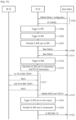
- FIG. 15 shows an example of sidelink data transmission of MAC PDU from a UE according to an exemplary embodiment of the present disclosure.
- FIG. 15 is only exemplary, and is not limited thereto.
- the present disclosure can be applied to resource reselection of an uplink configured grant for uplink data transmission as well.
- steps performed by TX UE are illustrated as being performed by UE for simplicity.
- the UE may be configured with sidelink mode 1 in which the UE reports SL buffer status via SL-BSR.
- the UE may also receive a UL grant via PDCCH from a network.
- step S1503 the UE may trigger a SL-BSR.
- the UE may trigger a BSR when UL data is available for transmission for one or more logical channels.
- the UE may prioritize the SL-BSR over the BSR and includes the SL-BSR in a MAC PDU to be transmitted by using a UL grant.
- the SL-BSR prioritization conditions may comprise:
- the UE may prioritize the BSR over the SL BSR and includes the BSR in the MAC PDU to be transmitted by using a UL grant.
- step S1509 in case that the UE prioritizes the SL-BSR, when the UL transmission of the SL-BSR collides with a SL transmission or PUCCH transmission triggered either for requesting SL-SCH resources or for conveying sidelink HARQ feedback to the network, the UE may prioritize the UL transmission of the SL-BSR over the SL transmission and/or the PUCCH transmission. In this case, the UE may skip the SL transmission or the PUCCH transmission.
- the UL grant may not correspond to either message A of the two-step RACH or message 3 of the four-step RACH.
- the UE may prioritize the UL transmission of the SL-BSR over the SL transmission.
- the UE may prioritize the UL transmission of the SL-BSR over the SL transmission.
- the UE may transmit the MAC PDU including the SL-BSR by using the UL grant.
- the UE may receive a grant (i.e., sidelink grant) from a network by receiving a downlink control information (DCI) in PDCCH.
- the DCI may include an allocated sidelink resource corresponding to the sidelink grant.
- the UE may use the sidelink grant for transmission to the RX UE.
- step S1513 the UE may trigger SL-BSR.
- the UE may deprioritize a UL transmission of the SL-BSR over SL transmission and PUCCH transmission. That is, the UE may prioritize the SL transmission and/or PUCCH transmission over the UL transmission of the SL-BSR.
- the UE may prioritize the SL transmission over the UL transmission of the SL-BSR, if the SL transmission carries a MAC PDU serving the logical channel(s) of which the highest priority value is lower than equal to the SL threshold, in case 1 and/or case 2.
- the UE may prioritize the PUCCH transmission over the UL transmission of the SL-BSR, if the PUCCH transmission was triggered for requesting SL-SCH resources and the PUCCH resource corresponds to a logical channel of which the highest priority value (or the lowest priority value) is lower than or equal to the SL threshold, or if the PUCCH transmission was triggered for conveying sidelink HARQ feedback and the sidelink HARQ feedback responds to a transmission of a MAC PDU carrying logical channels of which the highest priority value (or the lowest priority value) is lower than or equal to the SL threshold, in case 1 and/or case 2.
- the UE may transmit the SL transmission.
- the UE may transmit an initial transmission and/or a retransmission of MAC PDU, and receive HARQ ACK feedback which is NACK in this example.
- step S1519 if the PUCCH transmission is prioritized, the UE may transmit the PUCCH transmission. For example, the UE may transmit sidelink NACK over PUCCH to the network.
- step S1521 the UE may trigger SL-BSR due to timer expiry.
- the UE may prioritize SL-BSR over SL transmission.
- step S1525 the UE may transmit SL-BSR to the network.
- the UL transmissions and SL transmissions can be performed for different radio access technologies (RATs) or the same RAT.
- RATs radio access technologies
- the present disclosure can be also applied to prioritization of different uplink transmissions to different base stations, for example, different uplink transmissions for dual connectivity or carrier aggregation in uplink.
- the RX UE in Figure 15 can be replaced by the same or a different base station.
- each HARQ process may be associated with a HARQ buffer.
- New transmissions may be performed on the resource and with the MCS indicated on either PDCCH, Random Access Response, or RRC.
- Retransmissions may be performed on the resource and, if provided, with the MCS indicated on PDCCH, or on the same resource and with the same MCS as was used for last made transmission attempt within a bundle.
- the HARQ process shall:
- the HARQ process shall:
- the HARQ process shall:
- Type 1 and Type 2 may be configured with a single BWP. Multiple configurations can be active simultaneously on the BWP. For Type 2, activation and deactivation may be independent.
- RRC may be configure the following parameters when the configured grant Type 1 is configured:
- RRC may configure the following parameters when the configured grant Type 2 is configured:
- the MAC entity Upon configuration of a configured grant Type 1, the MAC entity shall for each configured sidelink grant: 1> initialise or re-initialise the configured sidelink grant to determine the set of PSCCH durations and the set of PSSCH durations for transmissions of multiple MAC PDUs.
- the MAC entity shall:
- the MAC entity shall clear the corresponding configured sidelink grant immediately after first transmission of Configured Grant Confirmation triggered by the configured sidelink grant deactivation.
- sidelink grant may be received dynamically on the PDCCH, configured semi-persistently by RRC or autonomously selected by the MAC entity.
- the MAC entity shall have a sidelink grant on an active SL BWP to determine a set of PSSCH duration(s) in which transmission of SCI occurs and a set of PSSCH duration(s) in which transmission of SL-SCH associated with the SCI occurs.
- the MAC layer may receive HARQ information from lower layers.
- the MAC entity shall for each PDCCH occasion and for each grant received for this PDCCH occasion:
- the MAC entity shall for each Sidelink process:
- the MAC entity shall for each PSSCH duration: 1> for each configured sidelink grant occurring in this PSSCH duration: 2> deliver the sidelink grant and the associated HARQ information to the Sidelink HARQ Entity for this PSSCH duration.
- the MAC entity shall for the Sidelink process:
- the MAC entity may include at most one Sidelink HARQ entity for transmission on SL-SCH, which maintains a number of parallel Sidelink processes.
- a sidelink process may be configured for transmissions of multiple MAC PDUs.
- a delivered sidelink grant and its associated HARQ information and QoS information may be associated with a Sidelink process.
- Each Sidelink process may support one TB.
- the Sidelink HARQ Entity shall: 1> associate a Sidelink process to this grant, and for each associated Sidelink process:
- the Sidelink process may be associated with a HARQ buffer.
- New transmissions and retransmissions may be performed on the resource indicated in the sidelink grant and with the MCS.
- the process may maintain a counter SL_RESOURCE_RESELECTION_COUNTER. For other configurations of the sidelink process, this counter may not be available.
- the Sidelink process shall:
- the Sidelink process shall:
- the Sidelink process shall:
- the transmission of the MAC PDU may be prioritized over uplink transmissions of the MAC entity or the other MAC entity if the following conditions are met:
- the priority value of the MAC CE or SCCH carrying measured result of SL-CSI/RI on sidelink transmissions for a destination to be transmitted in sidelink may be determined as:
- the priority value of the MAC CE may be higher than the priority value of PC5-RRC and PC5-S and lower than a priority value of any data from STCH. (i.e. the priority level is lower than the priority level of PC5-RRC and PC5-S and higher than a priority level of any data from STCH)
- the transmission of the MAC PDU may be prioritized over uplink transmissions of the MAC entity or the other MAC entity if the following conditions are met:
- the MAC entity shall for each PSSCH transmission of the MAC PDU1 carrying the logical channels: 1> for a PSFCH duration during which the MAC entity monitors PSFCH for a PSSCH transmission of the MAC PDU1 from the associated Sidelink process:
- the sidelink Logical Channel Prioritization procedure may be applied whenever a new transmission is performed.
- RRC may control the scheduling of sidelink data by signalling for each logical channel:
- RRC may additionally control the LCP procedure by configuring mapping restrictions for each logical channel:
- the following UE variable may be used for the Logical channel prioritization procedure:
- the MAC entity shall initialize [SBj] of the logical channel to zero when the logical channel is established.
- the MAC entity For each logical channel j , the MAC entity shall:
- the MAC entity shall for each SCI corresponding to a new transmission:
- the MAC entity shall for each SCI corresponding to a new transmission: 1> allocate resources to the logical channels as follows:
- the UE shall also follow the rules below during the SL scheduling procedures above:
- the MAC entity shall not generate a MAC PDU for the HARQ entity if the following conditions are satisfied:
- Logical channels shall be prioritised in accordance with the following order (highest priority listed first) for a cast type for a pair of Source/Destination Layer-2 IDs:
- UE may measures sidelink transmission and report SL-CSI/RI to a peer UE via either a MAC CE or a RRC message over SCCH with RLC TM.
- the UE may have different priorities for PC5-S signaling (and/or RRC messages) depending on whether PC5-RRC connection or PC5-S unicast link is established or not. For example, the priority value of PC5-S signaling from SCCH before PC5-RRC connection (or PC5-S unicast link establishment) may be lower than the priority value PC5-S signaling from SCCH after PC5-RRC connection(or PC5-S unicast link establishment). Alternatively, the priority value of PC5-S signaling from SCCH before PC5-RRC connection (or PC5-S unicast link establishment) may be higher than the priority value of PC5-S signaling from SCCH after PC5-RRC connection(or PC5-S unicast link establishment).
- the priority value of RRC signaling from SCCH before PC5-RRC connection may be lower than the priority value of RRC signaling from SCCH after PC5-RRC connection(or PC5-S unicast link establishment).
- the priority value of RRC signaling from SCCH before P6C5-RRC connection may be higher than the priority value of RRC signaling from SCCH after PC5-RRC connection(or PC5-S unicast link establishment).
- the priority value of RRC signaling from SCCH before PC5-RRC connection may be lower than the priority value of PC5-S signaling from SCCH after PC5-RRC connection(or PC5-S unicast link establishment).
- the priority value of RRC signaling from SCCH before PC5-RRC connection may be higher than the priority value of PC5-S signaling from SCCH after PC5-RRC connection(or PC5-S unicast link establishment).
- the priority of the MAC CE or the RRC message may be set to the hightest priority of the logical channels belonging to the destination and the associated cast type.
- the priority value of a signaling may be indicated in SCI scheduling the signaling on PSSCH and also used for prioritization between UL and SL transmissions, between PUCCH transmission and SL transmission, or between PSFCH reception and SL transmission.
- one TB and the associated HARQ information may be received from the Sidelink HARQ Entity.
- the Sidelink process shall:
- the MAC subheader may comprise the following fields:
- the MAC subheader may be octet aligned.
- Table 5 shows an example of values of V for SL-SCH: [Table 5] Index LCID values 0 Reserved 1 Unicast 2 Groupcast 3 Broadcast
- Table 6 shows an example of values of LCID for SL-SCH: [Table 6] Index LCID values 0 Reserved 1 SCCH carrying PC5-S signaling before PC5-RRC connection (or PC5-S unicast link establishment) 2 SCCH carrying RRC signaling before PC5-RRC connection 3 SCCH carrying PC5-S signaling after PC5-RRC connection(or PC5-S unicast link establishment) 4 SCCH carrying RRC signaling after PC5-RRC connection 5 SCCH carrying CSI/RI or MAC CE carrying CSI/RI 6-21 Identity of the logical channel 22-62 Reserved 63 Padding
- FIG. 16 shows an example of a method for prioritizing a specific BSR according to the claimed embodiment of the present disclosure. Steps illustrated in FIG. 16 may be performed by at least one of a wireless device and/or a UE.
- the wireless device may receive, from a network, information for a threshold related to a BSR.
- the BSR may comprise a SL BSR.
- the threshold may comprise a SL prioritization threshold, which may also be referred to as thresSL-TxPrioritization and/or sl-PrioritizationThres.
- the wireless device may prioritize a LCG for the BSR based on the threshold.
- a highest priority of one or more logical channels having data available for transmission in the LCG is lower than the threshold. That is, the wireless device may prioritize a LCG for the BSR based on that a highest priority of one or more logical channels having data available for transmission in the LCG is lower than the threshold.
- the data may comprise SL data.
- the wireless device may prioritize the BSR based on the prioritized LCG.
- the wireless device may create a MAC PDU comprising at least the prioritized BSR.
- the wireless device may create the MAC PDU based on a UL grant received from the network.
- the wireless device may transmit the MAC PDU.
- the wireless device may receive, from the network, a SL grant after transmitting the MAC PDU comprising the BSR to the network.
- the wireless device may transmit, to another wireless device, a SL data based on the SL grant.
- the MAC PDU may include LCGs in a decreasing order of a highest priority of at least one logical channel in each of the LCGs.
- the at least one logical channel man be a logical channel having data available for transmission.
- the MAC PDU may include LCGs in a decreasing order of a highest priority of at least one logical channel in each of the LCGs irrespective of a destination related to each of the LCGs.
- the SL BSR may be prioritized over other types of BSRs.
- the other types of BSRs may comprise an uplink (UL) BSR.
- the wireless device may prioritize the LCG for the SL BSR based on that: the highest priority of the one or more logical channels having data for transmission in the LCG is lower than the SL prioritization threshold; and a highest priority of one or more logical channels having a uplink (UL) data for transmission in any LCG is higher than a UL prioritization threshold.
- the UL prioritization threshold may be received from the network.
- the SL BSR may be prioritized based on that the UL grant is unable to accommodate a SL BSR MAC control element (CE) containing buffer status only for all prioritized LCGS having data available for transmission plus a subheader of the SL BSR.
- CE SL BSR MAC control element
- the SL BSR that is prioritized may be included in the MAC PDU with a higher priority than a uplink (UL) BSR.
- a non-prioritized SL BSR may be included in the MAC PDU with a lower priority than the UL BSR.
- the BSR may contain a buffer status for as many prioritized LCGs having data available for transmission as possible.
- the Sidelink Buffer Status reporting (SL-BSR) procedure may be used to provide the serving gNB with information about SL data volume in the MAC entity.
- RRC may configure the following parameters to control the SL-BSR:
- Each logical channel which belongs to a Destination may be allocated to an LCG.
- the maximum number of LCGs may be eight.
- the MAC entity may determine the amount of SL data available for a logical channel according to the data volume calculation procedure.
- a SL-BSR shall be triggered if any of the following events occur: 1> if the MAC entity has a [SL-RNTI] or [SLCS-RNTI]:
- the MAC entity shall:
- the MAC entity shall:
- the MAC entity may prioritize the SL-BSR for logical channel prioritization.
- the MAC entity may consider that the logical channel that triggered the SL-BSR is the highest priority logical channel that has data available for transmission at the time the SL-BSR is triggered.
- the MAC entity may consider that the logical channel that triggered the SL-BSR is the highest priority logical channel that has data available for transmission at the time the SL-BSR is triggered.
- the MAC entity shall: 1> if the sidelink Buffer Status reporting procedure determines that at least one SL-BSR has been triggered and not cancelled:
- UL-SCH resources may be considered available if the MAC entity has an active configuration for either type of configured uplink grants, or if the MAC entity has received a dynamic uplink grant, or if both of these conditions are met. If the MAC entity has determined at a given point in time that UL-SCH resources are available, this need not imply that UL-SCH resources are available for use at that point in time.
- a MAC PDU shall contain at most one SL-BSR MAC CE, even when multiple events have triggered a SL-BSR.
- the Regular SL-BSR and the Periodic SL-BSR shall have precedence over the padding SL-BSR.
- the MAC entity shall restart retxBSR-TimerSL upon reception of an SL grant for transmission of new data on any SL-SCH.
- the MAC entity shall restart retxBSR-TimerSL for each destination for the associated cast type upon reception of an SL grant associated to the destination for transmission of new data on any SL-SCH for the destination.
- All triggered SL-BSRs may be cancelled when the SL grant(s) can accommodate all pending data available for transmission. All BSRs triggered prior to MAC PDU assembly shall be cancelled when a MAC PDU is transmitted and this PDU includes a SL-BSR MAC CE which contains buffer status up to (and including) the last event that triggered a SL-BSR prior to the MAC PDU assembly.
- all triggered SL-BSRs including an LCG for the QoS flow, the logical channel, the priority, the destination, or the pair of the source and the destination shall be cancelled, and the related retx-BSR-TimerSL and periodic-BSR-TimerSL shall be stopped, when upper layers configure autonomous resource selection for the QoS flow, the logical channel, the priority, the destination, or the pair of the source and the destination.
- MAC PDU assembly can happen at any point in time between uplink grant reception and actual transmission of the corresponding MAC PDU.
- SL-BSR and SR can be triggered after the assembly of a MAC PDU which contains a SL-BSR MAC CE, but before the transmission of this MAC PDU.
- SL-BSR and SR can be triggered during MAC PDU assembly.
- FIG. 17 shows an example of a signal flow for prioritizing a specific BSR according to an exemplary embodiment of the present disclosure.
- a base station may transmit information for a threshold related to a BSR to a wireless device.
- the BSR may comprise a SL BSR.
- the threshold may comprise a SL prioritization threshold, which may also be referred to as thresSL-TxPrioritization and/or sl-PrioritizationThres.
- the wireless device may prioritize a LCG for the BSR based on the threshold.
- a highest priority of one or more logical channels having data available for transmission in the LCG is lower than the threshold. That is, the wireless device may prioritize a LCG for the BSR based on that a highest priority of one or more logical channels having data available for transmission in the LCG is lower than the threshold.
- the data may comprise SL data.
- the wireless device may prioritize the BSR based on the prioritized LCG.
- the wireless device may create a MAC PDU comprising at least the prioritized BSR.
- the wireless device may create the MAC PDU based on a UL grant received from the network.
- the BS may receive the MAC PDU from the wireless device.
- the BS may transmit, to the wireless device, a SL grant after receiving the MAC PDU comprising the BSR from the wireless device.
- the wireless device may transmit, to another wireless device, a SL data based on the SL grant.
- the BS in FIG. 17 may be an example of a second device 220 in FIG. 2 , and therefore, steps of the BS as illustrated in FIG. 17 may be implemented by the second device 220.
- the processor 221 may be configured to control the transceiver 223 to transmit information for a threshold related to a BSR to a wireless device.
- the wireless device may prioritize a LCG for the BSR based on the threshold.
- a highest priority of one or more logical channels having data available for transmission in the LCG is lower than the threshold.
- the wireless device may prioritize the BSR based on the prioritized LCG.
- the wireless device may create a MAC PDU comprising at least the prioritized BSR.
- the processor 221 may be configured to control the transceiver 223 to receive the MAC PDU from the wireless device.
- FIG. 18 shows a UE to implement an embodiment of the present disclosure.
- the present disclosure described above for UE side may be applied to this embodiment.
- the UE in FIG. 18 may be an example of first device 218 as illustrated in FIG. 2 .
- a UE includes a processor 1810 (i.e., processor 211), a power management module 1811, a battery 1812, a display 1813, a keypad 1814, a subscriber identification module (SIM) card 1815, a memory 1820 (i.e., memory 212), a transceiver 1830 (i.e., transceiver 213), one or more antennas 1831, a speaker 1840, and a microphone 1841.
- SIM subscriber identification module
- the processor 1810 may be configured to implement proposed functions, procedures and/or methods described in this description. Layers of the radio interface protocol may be implemented in the processor 1810.
- the processor 1810 may include application-specific integrated circuit (ASIC), other chipset, logic circuit and/or data processing device.
- the processor 1810 may be an application processor (AP).
- the processor 1810 may include at least one of a digital signal processor (DSP), a central processing unit (CPU), a graphics processing unit (GPU), a modem (modulator and demodulator).
- DSP digital signal processor
- CPU central processing unit
- GPU graphics processing unit
- modem modulator and demodulator
- processor 1810 may be found in SNAPDRAGON TM series of processors made by Qualcomm ® , EXYNOS TM series of processors made by Samsung ® , A series of processors made by Apple ® , HELIO TM series of processors made by MediaTek ® , ATOM TM series of processors made by Intel ® or a corresponding next generation processor.
- the processor 1810 may be configured to, or configured to control the transceiver 1830 to implement steps performed by the UE and/or the wireless device throughout the disclosure.
- the power management module 1811 manages power for the processor 1810 and/or the transceiver 1830.
- the battery 1812 supplies power to the power management module 1811.
- the display 1813 outputs results processed by the processor 1810.
- the keypad 1814 receives inputs to be used by the processor 1810.
- the keypad 1814 may be shown on the display 1813.
- the SIM card 1815 is an integrated circuit that is intended to securely store the international mobile subscriber identity (IMSI) number and its related key, which are used to identify and authenticate subscribers on mobile telephony devices (such as mobile phones and computers). It is also possible to store contact information on many SIM cards.
- IMSI international mobile subscriber identity
- the memory 1820 is operatively coupled with the processor 1810 and stores a variety of information to operate the processor 1810.
- the memory 1820 may include read-only memory (ROM), random access memory (RAM), flash memory, memory card, storage medium and/or other storage device.
- the transceiver 1830 is operatively coupled with the processor 1810, and transmits and/or receives a radio signal.
- the transceiver 1830 includes a transmitter and a receiver.
- the transceiver 1830 may include baseband circuitry to process radio frequency signals.
- the transceiver 1830 controls the one or more antennas 1831 to transmit and/or receive a radio signal.
- the speaker 1840 outputs sound-related results processed by the processor 1810.
- the microphone 1841 receives sound-related inputs to be used by the processor 1810.
- the processor 1810 may be configured to, or configured to control the transceiver 1830 to implement steps performed by the UE and/or the wireless device throughout the disclosure.
- the processor 1810 may configured to control the transceiver 1830 to receive, from a network, information for a threshold related to a BSR.
- the processor 1810 may configured to prioritize a LCG for the BSR based on the threshold.
- a highest priority of one or more logical channels having data available for transmission in the LCG is lower than the threshold.
- the processor 1810 may configured to prioritize the BSR based on the prioritized LCG.
- the processor 1810 may configured to create a MAC PDU comprising at least the prioritized BSR.
- the processor 1810 may configured to control the transceiver 1830 to transmit the MAC PDU.
- the MAC PDU may include LCGs in a decreasing order of a highest priority of at least one logical channel in each of the LCGs.
- the at least one logical channel man be a logical channel having data available for transmission.
- the MAC PDU may include LCGs in a decreasing order of a highest priority of at least one logical channel in each of the LCGs irrespective of a destination related to each of the LCGs.
- the SL BSR may be prioritized over other types of BSRs.
- the other types of BSRs may comprise an uplink (UL) BSR.
- the processor 1810 may be configured to prioritize the LCG for the SL BSR based on that: the highest priority of the one or more logical channels having data for transmission in the LCG is lower than the SL prioritization threshold; and a highest priority of one or more logical channels having a uplink (UL) data for transmission in any LCG is higher than a UL prioritization threshold.
- the UL prioritization threshold may be received from the network.
- the SL BSR may be prioritized based on that the UL grant is unable to accommodate a SL BSR MAC control element (CE) containing buffer status only for all prioritized LCGS having data available for transmission plus a subheader of the SL BSR.
- CE SL BSR MAC control element
- the SL BSR that is prioritized may be included in the MAC PDU with a higher priority than a uplink (UL) BSR.
- a non-prioritized SL BSR may be included in the MAC PDU with a lower priority than the UL BSR.
- the BSR may contain a buffer status for as many prioritized LCGs having data available for transmission as possible.
- FIG. 19 shows another example of a wireless communication system to which the technical features of the present disclosure can be applied.
- the wireless communication system may include a first device 1910 (i.e., first device 210) and a second device 1920 (i.e., second device 220).
- the first device 1910 may include at least one transceiver, such as a transceiver 1911, and at least one processing chip, such as a processing chip 1912.
- the processing chip 1912 may include at least one processor, such a processor 1913, and at least one memory, such as a memory 1914.
- the memory may be operably connectable to the processor 1913.
- the memory 1914 may store various types of information and/or instructions.
- the memory 1914 may store a software code 1915 which implements instructions that, when executed by the processor 1913, perform operations of the first device 910 described throughout the disclosure.
- the software code 1915 may implement instructions that, when executed by the processor 1913, perform the functions, procedures, and/or methods of the first device 1910 described throughout the disclosure.
- the software code 1915 may control the processor 1913 to perform one or more protocols.
- the software code 1915 may control the processor 1913 to perform one or more layers of the radio interface protocol.
- the second device 1920 may include at least one transceiver, such as a transceiver 1921, and at least one processing chip, such as a processing chip 1922.
- the processing chip 1922 may include at least one processor, such a processor 1923, and at least one memory, such as a memory 1924.
- the memory may be operably connectable to the processor 1923.
- the memory 1924 may store various types of information and/or instructions.
- the memory 1924 may store a software code 1925 which implements instructions that, when executed by the processor 1923, perform operations of the second device 1920 described throughout the disclosure.
- the software code 1925 may implement instructions that, when executed by the processor 1923, perform the functions, procedures, and/or methods of the second device 1920 described throughout the disclosure.
- the software code 1925 may control the processor 1923 to perform one or more protocols.
- the software code 1925 may control the processor 1923 to perform one or more layers of the radio interface protocol.
- the first device 1910 as illustrated in FIG. 19 may comprise a wireless device.
- the wireless device may comprise a transceiver 1911, a processing chip 1912.
- the processing chip 1912 may comprise a processor 1913, and a memory 1914.
- the memory 1914 may be operably connectable to the processor 1913.
- the memory 1914 may store various types of information and/or instructions.
- the memory 1914 may store a software code 1915 which implements instructions that, when executed by the processor 1913, perform operations comprising: receiving, from a network, information for a threshold related to a buffer status report (BSR); prioritizing a logical channel group (LCG) for the BSR based on the threshold, wherein a highest priority of one or more logical channels having data available for transmission in the LCG is lower than the threshold; prioritizing the BSR based on the prioritized LCG; creating a media access control (MAC) protocol data unit (PDU) comprising at least the prioritized BSR; and transmitting the MAC PDU.
- BSR buffer status report
- LCG logical channel group
- LCG logical channel group
- PDU media access control protocol data unit
- a computer-readable medium having recorded thereon a program for performing each step of a method on a computer comprises: receiving, from a network, information for a threshold related to a buffer status report (BSR); prioritizing a logical channel group (LCG) for the BSR based on the threshold, wherein a highest priority of one or more logical channels having data available for transmission in the LCG is lower than the threshold; prioritizing the BSR based on the prioritized LCG; creating a media access control (MAC) protocol data unit (PDU) comprising at least the prioritized BSR; and transmitting the MAC PDU.
- BSR buffer status report
- LCG logical channel group
- LCG logical channel group
- PDU media access control protocol data unit
- the present disclosure may be applied to various future technologies, such as AI, robots, autonomous-driving/self-driving vehicles, and/or extended reality (XR).
- future technologies such as AI, robots, autonomous-driving/self-driving vehicles, and/or extended reality (XR).
- XR extended reality
- AI refers to artificial intelligence and/or the field of studying methodology for making it.
- Machine learning is a field of studying methodologies that define and solve various problems dealt with in AI.
- Machine learning may be defined as an algorithm that enhances the performance of a task through a steady experience with any task.
- An artificial neural network is a model used in machine learning. It can mean a whole model of problem-solving ability, consisting of artificial neurons (nodes) that form a network of synapses.
- An ANN can be defined by a connection pattern between neurons in different layers, a learning process for updating model parameters, and/or an activation function for generating an output value.
- An ANN may include an input layer, an output layer, and optionally one or more hidden layers. Each layer may contain one or more neurons, and an ANN may include a synapse that links neurons to neurons.
- each neuron can output a summation of the activation function for input signals, weights, and deflections input through the synapse.
- Model parameters are parameters determined through learning, including deflection of neurons and/or weights of synaptic connections.
- the hyper-parameter means a parameter to be set in the machine learning algorithm before learning, and includes a learning rate, a repetition number, a mini batch size, an initialization function, etc.
- the objective of the ANN learning can be seen as determining the model parameters that minimize the loss function.
- the loss function can be used as an index to determine optimal model parameters in learning process of ANN.
- Machine learning can be divided into supervised learning, unsupervised learning, and reinforcement learning, depending on the learning method.
- Supervised learning is a method of learning ANN with labels given to learning data. Labels are the answers (or result values) that ANN must infer when learning data is input to ANN.
- Unsupervised learning can mean a method of learning ANN without labels given to learning data.
- Reinforcement learning can mean a learning method in which an agent defined in an environment learns to select a behavior and/or sequence of actions that maximizes cumulative compensation in each state.
- Machine learning which is implemented as a deep neural network (DNN) that includes multiple hidden layers among ANN, is also called deep learning. Deep learning is part of machine learning. In the following, machine learning is used to mean deep learning.
- DNN deep neural network
- FIG. 20 shows an example of an AI device to which the technical features of the present disclosure can be applied.
- the AI device 2000 may be implemented as a stationary device or a mobile device, such as a TV, a projector, a mobile phone, a smartphone, a desktop computer, a notebook, a digital broadcasting terminal, a PDA, a PMP, a navigation device, a tablet PC, a wearable device, a set-top box (STB), a digital multimedia broadcasting (DMB) receiver, a radio, a washing machine, a refrigerator, a digital signage, a robot, a vehicle, etc.
- a mobile device such as a TV, a projector, a mobile phone, a smartphone, a desktop computer, a notebook, a digital broadcasting terminal, a PDA, a PMP, a navigation device, a tablet PC, a wearable device, a set-top box (STB), a digital multimedia broadcasting (DMB) receiver, a radio, a washing machine, a refrigerator, a digital signage, a robot, a vehicle, etc.
- DMB digital multimedia
- the AI device 2000 may include a communication part 2010, an input part 2020, a learning processor 2030, a sensing part 2040, an output part 2050, a memory 2060, and a processor 2070.
- the communication part 2010 can transmit and/or receive data to and/or from external devices such as the AI devices and the AI server using wire and/or wireless communication technology.
- the communication part 2010 can transmit and/or receive sensor information, a user input, a learning model, and a control signal with external devices.
- the communication technology used by the communication part 2010 may include a global system for mobile communication (GSM), a code division multiple access (CDMA), an LTE/LTE-A, a 5G, a WLAN, a Wi-Fi, Bluetooth TM , radio frequency identification (RFID), infrared data association (IrDA), ZigBee, and/or near field communication (NFC).
- GSM global system for mobile communication
- CDMA code division multiple access
- LTE/LTE-A Long Term Evolution
- 5G Fifth Generation
- WLAN Fifth Generation
- Wi-Fi Wireless Fidelity
- Bluetooth TM Bluetooth TM
- RFID radio frequency identification
- IrDA infrared data association
- ZigBee ZigBee
- the input part 2020 can acquire various kinds of data.
- the input part 2020 may include a camera for inputting a video signal, a microphone for receiving an audio signal, and a user input part for receiving information from a user.
- a camera and/or a microphone may be treated as a sensor, and a signal obtained from a camera and/or a microphone may be referred to as sensing data and/or sensor information.
- the input part 2020 can acquire input data to be used when acquiring an output using learning data and a learning model for model learning.
- the input part 2020 may obtain raw input data, in which case the processor 2070 or the learning processor 2030 may extract input features by preprocessing the input data.
- the learning processor 2030 may learn a model composed of an ANN using learning data.
- the learned ANN can be referred to as a learning model.
- the learning model can be used to infer result values for new input data rather than learning data, and the inferred values can be used as a basis for determining which actions to perform.
- the learning processor 2030 may perform AI processing together with the learning processor of the AI server.
- the learning processor 2030 may include a memory integrated and/or implemented in the AI device 2000. Alternatively, the learning processor 2030 may be implemented using the memory 2060, an external memory directly coupled to the AI device 2000, and/or a memory maintained in an external device.
- the sensing part 2040 may acquire at least one of internal information of the AI device 2000, environment information of the AI device 2000, and/or the user information using various sensors.
- the sensors included in the sensing part 2040 may include a proximity sensor, an illuminance sensor, an acceleration sensor, a magnetic sensor, a gyro sensor, an inertial sensor, an RGB sensor, an IR sensor, a fingerprint recognition sensor, an ultrasonic sensor, an optical sensor, a microphone, a light detection and ranging (LIDAR), and/or a radar.
- the output part 2050 may generate an output related to visual, auditory, tactile, etc.
- the output part 2050 may include a display unit for outputting visual information, a speaker for outputting auditory information, and/or a haptic module for outputting tactile information.
- the memory 2060 may store data that supports various functions of the AI device 2000.
- the memory 2060 may store input data acquired by the input part 2020, learning data, a learning model, a learning history, etc.
- the processor 2070 may determine at least one executable operation of the AI device 2000 based on information determined and/or generated using a data analysis algorithm and/or a machine learning algorithm. The processor 2070 may then control the components of the AI device 2000 to perform the determined operation. The processor 2070 may request, retrieve, receive, and/or utilize data in the learning processor 2030 and/or the memory 2060, and may control the components of the AI device 2000 to execute the predicted operation and/or the operation determined to be desirable among the at least one executable operation. The processor 2070 may generate a control signal for controlling the external device, and may transmit the generated control signal to the external device, when the external device needs to be linked to perform the determined operation.
- the processor 2070 may obtain the intention information for the user input and determine the user's requirements based on the obtained intention information.
- the processor 2070 may use at least one of a speech-to-text (STT) engine for converting speech input into a text string and/or a natural language processing (NLP) engine for acquiring intention information of a natural language, to obtain the intention information corresponding to the user input.
- STT speech-to-text
- NLP natural language processing
- At least one of the STT engine and/or the NLP engine may be configured as an ANN, at least a part of which is learned according to a machine learning algorithm.
- At least one of the STT engine and/or the NLP engine may be learned by the learning processor 2030 and/or learned by the learning processor of the AI server, and/or learned by their distributed processing.
- the processor 2070 may collect history information including the operation contents of the AI device 2000 and/or the user's feedback on the operation, etc.
- the processor 2070 may store the collected history information in the memory 2060 and/or the learning processor 2030, and/or transmit to an external device such as the AI server.
- the collected history information can be used to update the learning model.
- the processor 2070 may control at least some of the components of AI device 2000 to drive an application program stored in memory 2060. Furthermore, the processor 2070 may operate two or more of the components included in the AI device 2000 in combination with each other for driving the application program.
- FIG. 21 shows an example of an AI system to which the technical features of the present disclosure can be applied.
- an AI server 2120 at least one of an AI server 2120, a robot 2110a, an autonomous vehicle 2110b, an XR device 2110c, a smartphone 2110d and/or a home appliance 2110e is connected to a cloud network 2100.
- the robot 2110a, the autonomous vehicle 2110b, the XR device 2110c, the smartphone 2110d, and/or the home appliance 2110e to which the AI technology is applied may be referred to as AI devices 2110a to 2110e.
- the cloud network 2100 may refer to a network that forms part of a cloud computing infrastructure and/or resides in a cloud computing infrastructure.
- the cloud network 2100 may be configured using a 3G network, a 4G or LTE network, and/or a 5G network. That is, each of the devices 2110a to 2110e and 2120 consisting the AI system may be connected to each other through the cloud network 2100.
- each of the devices 2110a to 2110e and 2120 may communicate with each other through a base station, but may directly communicate with each other without using a base station.
- the AI server 2120 may include a server for performing AI processing and a server for performing operations on big data.
- the AI server 2120 is connected to at least one or more of AI devices constituting the AI system, i.e. the robot 2110a, the autonomous vehicle 2110b, the XR device 2110c, the smartphone 2110d and/or the home appliance 2110e through the cloud network 2100, and may assist at least some AI processing of the connected AI devices 2110a to 2110e.
- the AI server 2120 can learn the ANN according to the machine learning algorithm on behalf of the AI devices 2110a to 2110e, and can directly store the learning models and/or transmit them to the AI devices 2110a to 2110e.
- the AI server 2120 may receive the input data from the AI devices 2110a to 2110e, infer the result value with respect to the received input data using the learning model, generate a response and/or a control command based on the inferred result value, and transmit the generated data to the AI devices 2110a to 2110e.
- the AI devices 2110a to 2110e may directly infer a result value for the input data using a learning model, and generate a response and/or a control command based on the inferred result value.
- the AI devices 2110a to 2110e to which the technical features of the present disclosure can be applied will be described.
- the AI devices 2110a to 2110e shown in FIG. 21 can be seen as specific embodiments of the AI device 2000 shown in FIG. 20 .
- the present disclosure can have various advantageous effects.
- a UE performing UL and SL transmissions by using priorities of UL and SL can properly prioritize one of UL and SL transmissions for transmissions of packets considering service characteristics and requirements.
- the present disclosure is beneficial when different transmissions collide (e.g. between uplink and sidelink or between different RATs).
- the present disclosure is beneficial in that the system can provide proper prioritization of different types of transmissions in collision for data transmissions for a UE performing multiple transmissions.
- SL-BSR may have a higher priority than UL-BSR so that the SL-BSR with the higher priority can be reported preferentially thatn the UL-BSR.
Landscapes
- Engineering & Computer Science (AREA)
- Computer Networks & Wireless Communication (AREA)
- Signal Processing (AREA)
- Mobile Radio Communication Systems (AREA)
Claims (8)
- Procédé exécuté par un dispositif sans fil dans un système de communication sans fil, le procédé comprenant:la réception (S1601), en provenance d'un réseau, d'un seuil de priorité de liaison latérale, SL, et d'un seuil de priorité de liaison montante, UL, associé à un rapport d'état de mémoire tampon;le déclenchement d'un premier rapport d'état de mémoire tampon, BSR, et d'un second BSR, dans lequel le premier BRS est un SL-BSR utilisé pour fournir au réseau des informations concernant le volume de données SL et le second BSR est un BSR utilisé pour fournir au réseau des informations concernant le volume de données UL; caractérisé parle fait de donner la priorité (S1605) au premier BSR par rapport au second BSR en fonction du premier BSR contenant l'état de mémoire tampon pour un ou plusieurs premiers groupes de canaux logiques, LCG, qui sont prioritaires, dans lequel le ou les LCG pour une ou plusieurs destinations sont prioritaires en fonction de:i) une valeur d'une priorité la plus élevée des canaux logiques qui appartiennent au(x) premier(s) LCG et contiennent les données SL pour le ou les destinations étant inférieure à un seuil de priorité SL; etii) une valeur d'une priorité la plus élevée des canaux logiques qui appartiennent au(x) second(s) LCG et contiennent les données UL étant supérieure ou égale au seuil de priorité UL;la création (S1607) d'une unité de données de protocole, PDU, de contrôle d'accès au support, MAC, comprenant au moins le premier BSR prioritaire; etla transmission (S1609), au réseau, de la MAC PDU.
- Procédé selon la revendication 1, dans lequel la création de la MAC PDU comprend la création de la MAC PDU en fonction d'une attribution UL, et
dans lequel le premier BSR est prioritaire en fonction de l'attribution UL n'étant pas apte à recevoir un élément de commande, CE, de SL BSR MAC, contenant l'état de mémoire tampon uniquement pour tous les LCG prioritaires ayant des données disponibles pour la transmission plus un sous-entête du premier BSR. - Procédé selon la revendication 1, dans lequel le premier BSR qui est prioritaire est inclus dans la MAC PDU ayant une priorité supérieure à celle du second BSR; et
dans lequel un SL BSR non prioritaire est inclus dans la MAC PDU ayant une priorité inférieure à celle du second BSR. - Procédé selon la revendication 1, dans lequel le premier BSR contient un état de mémoire tampon pour le plus grand nombre possible de LCG prioritaires ayant des données SL disponibles pour la transmission.
- Procédé selon la revendication 1, comprenant en outre:la réception, en provenance du réseau, d'une attribution SL après la transmission de la MAC PDU comprenant le premier BSR au réseau; etla transmission à un autre dispositif sans fil, de données SL sur la base de l'attribution SL.
- Procédé selon la revendication 1, dans lequel le dispositif sans fil est en communication avec au moins l'un parmi un équipement utilisateur, un réseau, ou des véhicules autonomes autre que le dispositif sans fil.
- Dispositif sans fil (210) dans un système de communication sans fil comprenant:un émetteur-récepteur (213);une mémoire (212); etau moins un processeur (211) couplé fonctionnellement à l'émetteur-récepteur (213) et à la mémoire (212), configuré pour:amener l'émetteur-récepteur (213) à recevoir, en provenance d'un réseau, d'un seuil de priorité de liaison latérale, SL, et d'un seuil de priorité de liaison montante, UL, associé à un rapport d'état de mémoire tampon;déclencher un premier rapport d'état de mémoire tampon, BSR, et un second BSR, dans lequel le premier BRS est un SL-BSR utilisé pour fournir au réseau des informations concernant le volume de données SL et le second BSR est un BSR utilisé pour fournir au réseau des informations concernant le volume de données UL; caractérisé par le processeur qui est en outre configuré pour:
donner la priorité au premier BSR par rapport au second BSR en fonction du premier BSR contenant l'état de mémoire tampon pour un ou plusieurs premiers groupes de canaux logiques, LCG, qui sont prioritaires, dans lequel le ou les LCG pour une ou plusieurs destinations sont prioritaires en fonction de:i) une valeur d'une priorité la plus élevée des canaux logiques qui appartiennent au(x) premier(s) LCG et contiennent les données SL pour le ou les destinations étant inférieure à un seuil de priorité SL; etii) une valeur d'une priorité la plus élevée des canaux logiques qui appartiennent au(x) second(s) LCG et contiennent les données UL étant supérieure ou égale au seuil de priorité UL;créer une unité de données de protocole, PDU, de contrôle d'accès au support, MAC, comprenant au moins le premier BSR prioritaire; etamener l'émetteur-récepteur (213) à transmettre, au réseau, la MAC PDU. - Support lisible par ordinateur sur lequel est enregistré un programme pour réaliser chaque étape d'un procédé sur un ordinateur, le procédé comprenant:la réception (S1601), en provenance d'un réseau, d'un seuil de priorité de liaison latérale, SL, et d'un seuil de priorité de liaison montante, UL, associé à un rapport d'état de mémoire tampon;le déclenchement d'un premier rapport d'état de mémoire tampon, BSR, et d'un second BSR, dans lequel le premier BRS est un SL-BSR utilisé pour fournir au réseau des informations concernant le volume de données SL et le second BSR est un BSR utilisé pour fournir au réseau des informations concernant le volume de données UL; caractérisé parle fait de donner la priorité (S1605) au premier BSR par rapport au second BSR en fonction du premier BSR contenant l'état de mémoire tampon pour un ou plusieurs premiers groupes de canaux logiques, LCG, qui sont prioritaires, dans lequel le ou les LCG pour une ou plusieurs destinations sont prioritaires en fonction de:i) une valeur d'une priorité la plus élevée des canaux logiques qui appartiennent au(x) premier(s) LCG et contiennent les données SL pour le ou les destinations étant inférieure à un seuil de priorité SL; etii) une valeur d'une priorité la plus élevée des canaux logiques qui appartiennent au(x) second(s) LCG et contiennent les données UL étant supérieure ou égale au seuil de priorité UL;la création (S1607) d'une unité de données de protocole, PDU, de contrôle d'accès au support, MAC, comprenant au moins le premier BSR prioritaire; etla transmission (S1609), au réseau, de la MAC PDU.
Applications Claiming Priority (2)
| Application Number | Priority Date | Filing Date | Title |
|---|---|---|---|
| KR20190135912 | 2019-10-29 | ||
| PCT/KR2020/014919 WO2021086059A1 (fr) | 2019-10-29 | 2020-10-29 | Procédé et appareil pour la priorité de transmission dans un système de communication sans fil |
Publications (3)
| Publication Number | Publication Date |
|---|---|
| EP4035482A1 EP4035482A1 (fr) | 2022-08-03 |
| EP4035482A4 EP4035482A4 (fr) | 2023-01-11 |
| EP4035482B1 true EP4035482B1 (fr) | 2024-06-19 |
Family
ID=75716071
Family Applications (1)
| Application Number | Title | Priority Date | Filing Date |
|---|---|---|---|
| EP20880797.4A Active EP4035482B1 (fr) | 2019-10-29 | 2020-10-29 | Procédé et appareil pour la priorité de transmission dans un système de communication sans fil |
Country Status (6)
| Country | Link |
|---|---|
| US (1) | US12414148B2 (fr) |
| EP (1) | EP4035482B1 (fr) |
| JP (1) | JP7371252B2 (fr) |
| KR (1) | KR102929640B1 (fr) |
| CN (1) | CN114616903B (fr) |
| WO (1) | WO2021086059A1 (fr) |
Families Citing this family (14)
| Publication number | Priority date | Publication date | Assignee | Title |
|---|---|---|---|---|
| US11470017B2 (en) * | 2019-07-30 | 2022-10-11 | At&T Intellectual Property I, L.P. | Immersive reality component management via a reduced competition core network component |
| WO2021091337A1 (fr) * | 2019-11-07 | 2021-05-14 | Lg Electronics Inc. | Procédé et appareil permettant la transmission de l'établissement des priorités dans un système de communication sans fil |
| WO2021120031A1 (fr) * | 2019-12-18 | 2021-06-24 | Mediatek Singapore Pte. Ltd. | Procédés et appareil de priorisation de transmission entre liaison montante et liaison latérale |
| CN113473614B (zh) * | 2020-03-30 | 2024-11-26 | 华为技术有限公司 | 确定资源的方法和装置 |
| CN113709806B (zh) * | 2020-05-20 | 2024-09-06 | 远传电信股份有限公司 | 基于ca及iab的用户设备及缓冲区状态上报取消方法 |
| KR20230062559A (ko) * | 2020-09-09 | 2023-05-09 | 엘지전자 주식회사 | 상이한 rat을 기반으로 sl 통신 및 ul 전송을 수행하는 방법 및 장치 |
| WO2022151132A1 (fr) * | 2021-01-14 | 2022-07-21 | Zte Corporation | Procédé et dispositif pour effectuer une transmission et une réception de liaison latérale |
| WO2022236577A1 (fr) * | 2021-05-10 | 2022-11-17 | 富士通株式会社 | Procédé et appareil de collaboration entre des dispositifs |
| CN115696273A (zh) * | 2021-07-29 | 2023-02-03 | 华为技术有限公司 | 通信方法、装置及系统 |
| CN116419311A (zh) * | 2021-12-29 | 2023-07-11 | 中国移动通信有限公司研究院 | 信息传输方法、装置、终端及网络设备 |
| GB2620552A (en) * | 2022-06-29 | 2024-01-17 | Nec Corp | Communication system |
| CN117956410A (zh) * | 2022-10-31 | 2024-04-30 | 夏普株式会社 | 由用户设备执行的方法及用户设备 |
| CN118250742A (zh) * | 2022-12-23 | 2024-06-25 | 上海朗帛通信技术有限公司 | 一种被用于无线通信的通信节点中的方法和装置 |
| WO2025234606A1 (fr) * | 2024-05-10 | 2025-11-13 | 삼성전자주식회사 | Appareil, procédé et support de stockage pour l'allocation de ressources pour un service d'urgence |
Family Cites Families (8)
| Publication number | Priority date | Publication date | Assignee | Title |
|---|---|---|---|---|
| EP3051736B1 (fr) * | 2015-01-30 | 2020-04-29 | Panasonic Intellectual Property Corporation of America | Établissement de priorités dans la procédure de hiérarchisation de canaux logiques sur des communications directes ProSe |
| JP6669853B2 (ja) * | 2015-08-12 | 2020-03-18 | エルジー エレクトロニクス インコーポレイティド | D2d通信システムにおいてバッファ状態報告を行う方法及びその装置 |
| US10374916B2 (en) * | 2016-08-04 | 2019-08-06 | Lg Electronics Inc. | Method for transmitting a buffer status report in a communication system and device therefor |
| WO2019139319A1 (fr) * | 2018-01-11 | 2019-07-18 | Lg Electronics Inc. | Dispositif de communication, dispositif de traitement et procédé de transmission de données en liaison montante |
| WO2020006366A1 (fr) * | 2018-06-28 | 2020-01-02 | Convida Wireless, Llc | Procédures de priorisation pour une transmission de données de canal partagé de liaison latérale nr v2x |
| CN116405902A (zh) * | 2018-08-10 | 2023-07-07 | 中兴通讯股份有限公司 | 车联网中直通链路的资源配置方法及装置 |
| WO2021021892A1 (fr) * | 2019-07-31 | 2021-02-04 | Idac Holdings, Inc. | Opération simultanée de liaison montante et de liaison latérale |
| CN119603725A (zh) * | 2019-09-30 | 2025-03-11 | 华为技术有限公司 | 一种通信方法及装置 |
-
2020
- 2020-10-29 JP JP2022525424A patent/JP7371252B2/ja active Active
- 2020-10-29 WO PCT/KR2020/014919 patent/WO2021086059A1/fr not_active Ceased
- 2020-10-29 KR KR1020227015831A patent/KR102929640B1/ko active Active
- 2020-10-29 EP EP20880797.4A patent/EP4035482B1/fr active Active
- 2020-10-29 US US17/627,526 patent/US12414148B2/en active Active
- 2020-10-29 CN CN202080075737.3A patent/CN114616903B/zh active Active
Non-Patent Citations (1)
| Title |
|---|
| LENOVO ET AL: "Remaining issue for prioritization for NR V2X", vol. RAN WG2, no. ChongQing, China; 20191014 - 20191018, 3 October 2019 (2019-10-03), XP051804030, Retrieved from the Internet <URL:https://ftp.3gpp.org/tsg_ran/WG2_RL2/TSGR2_107bis/Docs/R2-1912913.zip R2-1912913 Prioritization for NR V2X-v1.doc> [retrieved on 20191003] * |
Also Published As
| Publication number | Publication date |
|---|---|
| JP2023500287A (ja) | 2023-01-05 |
| KR102929640B1 (ko) | 2026-02-24 |
| US12414148B2 (en) | 2025-09-09 |
| KR20220082027A (ko) | 2022-06-16 |
| CN114616903A (zh) | 2022-06-10 |
| JP7371252B2 (ja) | 2023-10-30 |
| EP4035482A4 (fr) | 2023-01-11 |
| US20220272721A1 (en) | 2022-08-25 |
| CN114616903B (zh) | 2025-06-20 |
| EP4035482A1 (fr) | 2022-08-03 |
| WO2021086059A1 (fr) | 2021-05-06 |
Similar Documents
| Publication | Publication Date | Title |
|---|---|---|
| US11343845B2 (en) | Method and apparatus for channel state reporting in wireless communication system | |
| US11337229B2 (en) | Method and apparatus for logical channel prioritization in wireless communication system | |
| EP4035482B1 (fr) | Procédé et appareil pour la priorité de transmission dans un système de communication sans fil | |
| US12034538B2 (en) | Method and apparatus for performing retransmission in wireless communication system | |
| US20220132558A1 (en) | Method and apparatus for selecting a sidelink resource for a sidelink csi reporting in a wireless communication system | |
| US12484023B2 (en) | Method and apparatus for sidelink retransmission in wireless communication system | |
| US11743910B2 (en) | Configured grants based on channel quality or repetition level | |
| US11564239B2 (en) | Method and apparatus for transmission prioritization in wireless communication system | |
| US11115890B2 (en) | Method and apparatus for triggering transmission carrier reselection procedure due to high congestion level in wireless communication system | |
| US11452015B2 (en) | Method and apparatus for triggering transmission carrier reselection procedure for deactivated duplication in wireless communication system | |
| US11722923B2 (en) | Cancelling SL CSI reporting in a wireless communication system | |
| US12267810B2 (en) | Method and apparatus for direct link management in wireless communication system | |
| US11924677B2 (en) | Method and apparatus for handling packet duplication based on congestion level of frequency in a wireless communication system | |
| US12284657B2 (en) | Method and apparatus for resource request in wireless communication system |
Legal Events
| Date | Code | Title | Description |
|---|---|---|---|
| STAA | Information on the status of an ep patent application or granted ep patent |
Free format text: STATUS: THE INTERNATIONAL PUBLICATION HAS BEEN MADE |
|
| PUAI | Public reference made under article 153(3) epc to a published international application that has entered the european phase |
Free format text: ORIGINAL CODE: 0009012 |
|
| STAA | Information on the status of an ep patent application or granted ep patent |
Free format text: STATUS: REQUEST FOR EXAMINATION WAS MADE |
|
| 17P | Request for examination filed |
Effective date: 20220422 |
|
| AK | Designated contracting states |
Kind code of ref document: A1 Designated state(s): AL AT BE BG CH CY CZ DE DK EE ES FI FR GB GR HR HU IE IS IT LI LT LU LV MC MK MT NL NO PL PT RO RS SE SI SK SM TR |
|
| A4 | Supplementary search report drawn up and despatched |
Effective date: 20221208 |
|
| RIC1 | Information provided on ipc code assigned before grant |
Ipc: H04W 92/18 20090101ALN20221202BHEP Ipc: H04W 28/02 20090101ALI20221202BHEP Ipc: H04W 72/12 20090101AFI20221202BHEP |
|
| DAV | Request for validation of the european patent (deleted) | ||
| DAX | Request for extension of the european patent (deleted) | ||
| STAA | Information on the status of an ep patent application or granted ep patent |
Free format text: STATUS: EXAMINATION IS IN PROGRESS |
|
| 17Q | First examination report despatched |
Effective date: 20230712 |
|
| GRAP | Despatch of communication of intention to grant a patent |
Free format text: ORIGINAL CODE: EPIDOSNIGR1 |
|
| RIC1 | Information provided on ipc code assigned before grant |
Ipc: H04W 92/18 20090101ALN20231218BHEP Ipc: H04W 72/566 20230101ALI20231218BHEP Ipc: H04W 72/21 20230101ALI20231218BHEP Ipc: H04W 28/02 20090101ALI20231218BHEP Ipc: H04W 72/12 20090101AFI20231218BHEP |
|
| STAA | Information on the status of an ep patent application or granted ep patent |
Free format text: STATUS: GRANT OF PATENT IS INTENDED |
|
| INTG | Intention to grant announced |
Effective date: 20240125 |
|
| GRAS | Grant fee paid |
Free format text: ORIGINAL CODE: EPIDOSNIGR3 |
|
| GRAA | (expected) grant |
Free format text: ORIGINAL CODE: 0009210 |
|
| STAA | Information on the status of an ep patent application or granted ep patent |
Free format text: STATUS: THE PATENT HAS BEEN GRANTED |
|
| AK | Designated contracting states |
Kind code of ref document: B1 Designated state(s): AL AT BE BG CH CY CZ DE DK EE ES FI FR GB GR HR HU IE IS IT LI LT LU LV MC MK MT NL NO PL PT RO RS SE SI SK SM TR |
|
| REG | Reference to a national code |
Ref country code: GB Ref legal event code: FG4D |
|
| REG | Reference to a national code |
Ref country code: CH Ref legal event code: EP |
|
| REG | Reference to a national code |
Ref country code: DE Ref legal event code: R096 Ref document number: 602020032783 Country of ref document: DE |
|
| PG25 | Lapsed in a contracting state [announced via postgrant information from national office to epo] |
Ref country code: BG Free format text: LAPSE BECAUSE OF FAILURE TO SUBMIT A TRANSLATION OF THE DESCRIPTION OR TO PAY THE FEE WITHIN THE PRESCRIBED TIME-LIMIT Effective date: 20240619 |
|
| PG25 | Lapsed in a contracting state [announced via postgrant information from national office to epo] |
Ref country code: HR Free format text: LAPSE BECAUSE OF FAILURE TO SUBMIT A TRANSLATION OF THE DESCRIPTION OR TO PAY THE FEE WITHIN THE PRESCRIBED TIME-LIMIT Effective date: 20240619 Ref country code: FI Free format text: LAPSE BECAUSE OF FAILURE TO SUBMIT A TRANSLATION OF THE DESCRIPTION OR TO PAY THE FEE WITHIN THE PRESCRIBED TIME-LIMIT Effective date: 20240619 |
|
| REG | Reference to a national code |
Ref country code: LT Ref legal event code: MG9D |
|
| PG25 | Lapsed in a contracting state [announced via postgrant information from national office to epo] |
Ref country code: GR Free format text: LAPSE BECAUSE OF FAILURE TO SUBMIT A TRANSLATION OF THE DESCRIPTION OR TO PAY THE FEE WITHIN THE PRESCRIBED TIME-LIMIT Effective date: 20240920 |
|
| REG | Reference to a national code |
Ref country code: NL Ref legal event code: MP Effective date: 20240619 |
|
| PG25 | Lapsed in a contracting state [announced via postgrant information from national office to epo] |
Ref country code: LV Free format text: LAPSE BECAUSE OF FAILURE TO SUBMIT A TRANSLATION OF THE DESCRIPTION OR TO PAY THE FEE WITHIN THE PRESCRIBED TIME-LIMIT Effective date: 20240619 |
|
| PG25 | Lapsed in a contracting state [announced via postgrant information from national office to epo] |
Ref country code: NO Free format text: LAPSE BECAUSE OF FAILURE TO SUBMIT A TRANSLATION OF THE DESCRIPTION OR TO PAY THE FEE WITHIN THE PRESCRIBED TIME-LIMIT Effective date: 20240919 Ref country code: LV Free format text: LAPSE BECAUSE OF FAILURE TO SUBMIT A TRANSLATION OF THE DESCRIPTION OR TO PAY THE FEE WITHIN THE PRESCRIBED TIME-LIMIT Effective date: 20240619 Ref country code: HR Free format text: LAPSE BECAUSE OF FAILURE TO SUBMIT A TRANSLATION OF THE DESCRIPTION OR TO PAY THE FEE WITHIN THE PRESCRIBED TIME-LIMIT Effective date: 20240619 Ref country code: GR Free format text: LAPSE BECAUSE OF FAILURE TO SUBMIT A TRANSLATION OF THE DESCRIPTION OR TO PAY THE FEE WITHIN THE PRESCRIBED TIME-LIMIT Effective date: 20240920 Ref country code: FI Free format text: LAPSE BECAUSE OF FAILURE TO SUBMIT A TRANSLATION OF THE DESCRIPTION OR TO PAY THE FEE WITHIN THE PRESCRIBED TIME-LIMIT Effective date: 20240619 Ref country code: BG Free format text: LAPSE BECAUSE OF FAILURE TO SUBMIT A TRANSLATION OF THE DESCRIPTION OR TO PAY THE FEE WITHIN THE PRESCRIBED TIME-LIMIT Effective date: 20240619 Ref country code: RS Free format text: LAPSE BECAUSE OF FAILURE TO SUBMIT A TRANSLATION OF THE DESCRIPTION OR TO PAY THE FEE WITHIN THE PRESCRIBED TIME-LIMIT Effective date: 20240919 |
|
| PG25 | Lapsed in a contracting state [announced via postgrant information from national office to epo] |
Ref country code: NL Free format text: LAPSE BECAUSE OF FAILURE TO SUBMIT A TRANSLATION OF THE DESCRIPTION OR TO PAY THE FEE WITHIN THE PRESCRIBED TIME-LIMIT Effective date: 20240619 |
|
| REG | Reference to a national code |
Ref country code: AT Ref legal event code: MK05 Ref document number: 1696810 Country of ref document: AT Kind code of ref document: T Effective date: 20240619 |
|
| PG25 | Lapsed in a contracting state [announced via postgrant information from national office to epo] |
Ref country code: NL Free format text: LAPSE BECAUSE OF FAILURE TO SUBMIT A TRANSLATION OF THE DESCRIPTION OR TO PAY THE FEE WITHIN THE PRESCRIBED TIME-LIMIT Effective date: 20240619 |
|
| PG25 | Lapsed in a contracting state [announced via postgrant information from national office to epo] |
Ref country code: PT Free format text: LAPSE BECAUSE OF FAILURE TO SUBMIT A TRANSLATION OF THE DESCRIPTION OR TO PAY THE FEE WITHIN THE PRESCRIBED TIME-LIMIT Effective date: 20241021 |
|
| PG25 | Lapsed in a contracting state [announced via postgrant information from national office to epo] |
Ref country code: PT Free format text: LAPSE BECAUSE OF FAILURE TO SUBMIT A TRANSLATION OF THE DESCRIPTION OR TO PAY THE FEE WITHIN THE PRESCRIBED TIME-LIMIT Effective date: 20241021 |
|
| PG25 | Lapsed in a contracting state [announced via postgrant information from national office to epo] |
Ref country code: PL Free format text: LAPSE BECAUSE OF FAILURE TO SUBMIT A TRANSLATION OF THE DESCRIPTION OR TO PAY THE FEE WITHIN THE PRESCRIBED TIME-LIMIT Effective date: 20240619 |
|
| PG25 | Lapsed in a contracting state [announced via postgrant information from national office to epo] |
Ref country code: EE Free format text: LAPSE BECAUSE OF FAILURE TO SUBMIT A TRANSLATION OF THE DESCRIPTION OR TO PAY THE FEE WITHIN THE PRESCRIBED TIME-LIMIT Effective date: 20240619 |
|
| PG25 | Lapsed in a contracting state [announced via postgrant information from national office to epo] |
Ref country code: IS Free format text: LAPSE BECAUSE OF FAILURE TO SUBMIT A TRANSLATION OF THE DESCRIPTION OR TO PAY THE FEE WITHIN THE PRESCRIBED TIME-LIMIT Effective date: 20241019 Ref country code: AT Free format text: LAPSE BECAUSE OF FAILURE TO SUBMIT A TRANSLATION OF THE DESCRIPTION OR TO PAY THE FEE WITHIN THE PRESCRIBED TIME-LIMIT Effective date: 20240619 |
|
| PG25 | Lapsed in a contracting state [announced via postgrant information from national office to epo] |
Ref country code: CZ Free format text: LAPSE BECAUSE OF FAILURE TO SUBMIT A TRANSLATION OF THE DESCRIPTION OR TO PAY THE FEE WITHIN THE PRESCRIBED TIME-LIMIT Effective date: 20240619 |
|
| PG25 | Lapsed in a contracting state [announced via postgrant information from national office to epo] |
Ref country code: SK Free format text: LAPSE BECAUSE OF FAILURE TO SUBMIT A TRANSLATION OF THE DESCRIPTION OR TO PAY THE FEE WITHIN THE PRESCRIBED TIME-LIMIT Effective date: 20240619 Ref country code: RO Free format text: LAPSE BECAUSE OF FAILURE TO SUBMIT A TRANSLATION OF THE DESCRIPTION OR TO PAY THE FEE WITHIN THE PRESCRIBED TIME-LIMIT Effective date: 20240619 |
|
| PG25 | Lapsed in a contracting state [announced via postgrant information from national office to epo] |
Ref country code: SM Free format text: LAPSE BECAUSE OF FAILURE TO SUBMIT A TRANSLATION OF THE DESCRIPTION OR TO PAY THE FEE WITHIN THE PRESCRIBED TIME-LIMIT Effective date: 20240619 Ref country code: ES Free format text: LAPSE BECAUSE OF FAILURE TO SUBMIT A TRANSLATION OF THE DESCRIPTION OR TO PAY THE FEE WITHIN THE PRESCRIBED TIME-LIMIT Effective date: 20240619 |
|
| PG25 | Lapsed in a contracting state [announced via postgrant information from national office to epo] |
Ref country code: SM Free format text: LAPSE BECAUSE OF FAILURE TO SUBMIT A TRANSLATION OF THE DESCRIPTION OR TO PAY THE FEE WITHIN THE PRESCRIBED TIME-LIMIT Effective date: 20240619 Ref country code: SK Free format text: LAPSE BECAUSE OF FAILURE TO SUBMIT A TRANSLATION OF THE DESCRIPTION OR TO PAY THE FEE WITHIN THE PRESCRIBED TIME-LIMIT Effective date: 20240619 Ref country code: RO Free format text: LAPSE BECAUSE OF FAILURE TO SUBMIT A TRANSLATION OF THE DESCRIPTION OR TO PAY THE FEE WITHIN THE PRESCRIBED TIME-LIMIT Effective date: 20240619 Ref country code: PL Free format text: LAPSE BECAUSE OF FAILURE TO SUBMIT A TRANSLATION OF THE DESCRIPTION OR TO PAY THE FEE WITHIN THE PRESCRIBED TIME-LIMIT Effective date: 20240619 Ref country code: IS Free format text: LAPSE BECAUSE OF FAILURE TO SUBMIT A TRANSLATION OF THE DESCRIPTION OR TO PAY THE FEE WITHIN THE PRESCRIBED TIME-LIMIT Effective date: 20241019 Ref country code: ES Free format text: LAPSE BECAUSE OF FAILURE TO SUBMIT A TRANSLATION OF THE DESCRIPTION OR TO PAY THE FEE WITHIN THE PRESCRIBED TIME-LIMIT Effective date: 20240619 Ref country code: EE Free format text: LAPSE BECAUSE OF FAILURE TO SUBMIT A TRANSLATION OF THE DESCRIPTION OR TO PAY THE FEE WITHIN THE PRESCRIBED TIME-LIMIT Effective date: 20240619 Ref country code: CZ Free format text: LAPSE BECAUSE OF FAILURE TO SUBMIT A TRANSLATION OF THE DESCRIPTION OR TO PAY THE FEE WITHIN THE PRESCRIBED TIME-LIMIT Effective date: 20240619 Ref country code: AT Free format text: LAPSE BECAUSE OF FAILURE TO SUBMIT A TRANSLATION OF THE DESCRIPTION OR TO PAY THE FEE WITHIN THE PRESCRIBED TIME-LIMIT Effective date: 20240619 |
|
| PG25 | Lapsed in a contracting state [announced via postgrant information from national office to epo] |
Ref country code: IT Free format text: LAPSE BECAUSE OF FAILURE TO SUBMIT A TRANSLATION OF THE DESCRIPTION OR TO PAY THE FEE WITHIN THE PRESCRIBED TIME-LIMIT Effective date: 20240619 |
|
| REG | Reference to a national code |
Ref country code: DE Ref legal event code: R097 Ref document number: 602020032783 Country of ref document: DE |
|
| PG25 | Lapsed in a contracting state [announced via postgrant information from national office to epo] |
Ref country code: DK Free format text: LAPSE BECAUSE OF FAILURE TO SUBMIT A TRANSLATION OF THE DESCRIPTION OR TO PAY THE FEE WITHIN THE PRESCRIBED TIME-LIMIT Effective date: 20240619 |
|
| PLBE | No opposition filed within time limit |
Free format text: ORIGINAL CODE: 0009261 |
|
| STAA | Information on the status of an ep patent application or granted ep patent |
Free format text: STATUS: NO OPPOSITION FILED WITHIN TIME LIMIT |
|
| 26N | No opposition filed |
Effective date: 20250320 |
|
| REG | Reference to a national code |
Ref country code: CH Ref legal event code: PL |
|
| PG25 | Lapsed in a contracting state [announced via postgrant information from national office to epo] |
Ref country code: MC Free format text: LAPSE BECAUSE OF FAILURE TO SUBMIT A TRANSLATION OF THE DESCRIPTION OR TO PAY THE FEE WITHIN THE PRESCRIBED TIME-LIMIT Effective date: 20240619 |
|
| PG25 | Lapsed in a contracting state [announced via postgrant information from national office to epo] |
Ref country code: BE Free format text: LAPSE BECAUSE OF NON-PAYMENT OF DUE FEES Effective date: 20241031 Ref country code: LU Free format text: LAPSE BECAUSE OF NON-PAYMENT OF DUE FEES Effective date: 20241029 |
|
| PG25 | Lapsed in a contracting state [announced via postgrant information from national office to epo] |
Ref country code: CH Free format text: LAPSE BECAUSE OF NON-PAYMENT OF DUE FEES Effective date: 20241031 |
|
| REG | Reference to a national code |
Ref country code: BE Ref legal event code: MM Effective date: 20241031 |
|
| PG25 | Lapsed in a contracting state [announced via postgrant information from national office to epo] |
Ref country code: SE Free format text: LAPSE BECAUSE OF FAILURE TO SUBMIT A TRANSLATION OF THE DESCRIPTION OR TO PAY THE FEE WITHIN THE PRESCRIBED TIME-LIMIT Effective date: 20240619 |
|
| PGFP | Annual fee paid to national office [announced via postgrant information from national office to epo] |
Ref country code: GB Payment date: 20250909 Year of fee payment: 6 |
|
| PGFP | Annual fee paid to national office [announced via postgrant information from national office to epo] |
Ref country code: FR Payment date: 20250909 Year of fee payment: 6 |
|
| PG25 | Lapsed in a contracting state [announced via postgrant information from national office to epo] |
Ref country code: IE Free format text: LAPSE BECAUSE OF NON-PAYMENT OF DUE FEES Effective date: 20241029 |
|
| PGFP | Annual fee paid to national office [announced via postgrant information from national office to epo] |
Ref country code: DE Payment date: 20250908 Year of fee payment: 6 |
|
| PG25 | Lapsed in a contracting state [announced via postgrant information from national office to epo] |
Ref country code: HU Free format text: LAPSE BECAUSE OF FAILURE TO SUBMIT A TRANSLATION OF THE DESCRIPTION OR TO PAY THE FEE WITHIN THE PRESCRIBED TIME-LIMIT; INVALID AB INITIO Effective date: 20201029 |
|
| PG25 | Lapsed in a contracting state [announced via postgrant information from national office to epo] |
Ref country code: CY Free format text: LAPSE BECAUSE OF FAILURE TO SUBMIT A TRANSLATION OF THE DESCRIPTION OR TO PAY THE FEE WITHIN THE PRESCRIBED TIME-LIMIT; INVALID AB INITIO Effective date: 20201029 |