EP4035522B1 - Heuwerbungsmaschine mit einer vorrichtung zum querverschieben des ernteguts - Google Patents
Heuwerbungsmaschine mit einer vorrichtung zum querverschieben des ernteguts Download PDFInfo
- Publication number
- EP4035522B1 EP4035522B1 EP22153556.0A EP22153556A EP4035522B1 EP 4035522 B1 EP4035522 B1 EP 4035522B1 EP 22153556 A EP22153556 A EP 22153556A EP 4035522 B1 EP4035522 B1 EP 4035522B1
- Authority
- EP
- European Patent Office
- Prior art keywords
- conveyors
- conveyor
- support element
- machine according
- machine
- Prior art date
- Legal status (The legal status is an assumption and is not a legal conclusion. Google has not performed a legal analysis and makes no representation as to the accuracy of the status listed.)
- Active
Links
Images



Classifications
-
- A—HUMAN NECESSITIES
- A01—AGRICULTURE; FORESTRY; ANIMAL HUSBANDRY; HUNTING; TRAPPING; FISHING
- A01D—HARVESTING; MOWING
- A01D57/00—Delivering mechanisms for harvesters or mowers
- A01D57/20—Delivering mechanisms for harvesters or mowers with conveyor belts
Definitions
- the invention relates to the field of agricultural machinery and concerns an agricultural haymaking machine, and more particularly a machine equipped with at least two conveyors for transverse movement of a crop.
- the invention relates to an agricultural haymaking machine of the type comprising a chassis carrying at least one device for transversely moving a crop, such as mown grass for example.
- Each moving device comprises at least two endless belt conveyors running on at least two rollers mounted in a frame. These conveyors are movable relative to the chassis and can occupy an adjacent position, in which a conveyor called the upstream conveyor can, when using the machine, transmit the crop to the or a second conveyor called the downstream conveyor, the internal lateral ends or internal rollers of the two conveyors concerned then being separated by a determined spacing distance, which it is desired to keep minimal in the adjacent position.
- each conveyor can move relative to the machine frame.
- the internal rollers of the two conveyors considered which are close to each other in an adjacent position, can thus be offset vertically relative to each other.
- a gap is left between the two conveyors in order to prevent them from colliding.
- the spacing distance refers to this gap left voluntarily.
- a major disadvantage of this spacing distance, even when it is minimal, is the fact that it induces crop losses between the two conveyors concerned.
- the present invention thus has the general aim of limiting the losses induced by this separation distance between two adjacent conveyors.
- the present invention also aims to provide an alternative solution, overcoming the drawbacks of this known solution.
- the invention relates to an agricultural haymaking machine as mentioned above and characterized in that it further comprises at least one support element providing a deposit surface, and in that this deposit surface has a width less than the spacing distance and is located between the internal lateral ends of the upstream and downstream conveyors considered, at least when the latter are in an adjacent position.
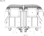
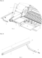
- FIG. 1A and partially the Figures 1B , 1C And 2 illustrate an agricultural haymaking machine (1) comprising a chassis (2) carrying at least one device (3) for transversely moving a crop (R), such as mown grass for example.
- Each device (3) comprises at least two endless belt conveyors (4, 4').
- Each endless belt (5) runs on at least two rollers (6, 6') mounted in a frame (6").
- the rollers (6) facing each other and defining the spacing distance (e) between them are called internal rollers.
- the rollers (6') opposite the latter in each conveyor (4, 4') are called external rollers (6').
- These conveyors (4, 4') are movable relative to the chassis (2).
- Each conveyor (4, 4') extends between an internal lateral end (4") and an external lateral end (4′′′).
- Each endless belt (5) is tensioned by the respective internal (6) and external (6') rollers. At least one of the rollers (6, 6') makes it possible to drive the associated endless belt (5) in rotation.
- the conveyors (4, 4') can occupy an adjacent position, in which an upstream conveyor (4) can, when using the machine (1), transmit the crop (R) to the or to a downstream conveyor (4').
- the crop (R) is then deposited on the ground by the downstream conveyor (4').
- the crop (R) is therefore deposited on the ground at the external lateral end (4′′′) of the downstream conveyor (4'), in an adjacent position.
- the crop (R) deposited on the ground forms a windrow. Thanks to the advance of the machine (1), the windrow is longitudinal to the direction of advance (A).
- the internal rollers (6) of the two conveyors (4, 4') considered are close to each other in an adjacent position.
- the inner roller (6) is located on the side of the inner lateral end (4") of the conveyor (4, 4') considered.
- Each outer roller (6') is at the outer lateral end (4′′′) of the conveyor (4, 4') considered.
- the inner lateral ends (4") of the two conveyors (4, 4') considered are opposite each other.
- the inner rollers (6) of the two conveyors (4, 4') concerned are separated by a spacing distance (e).
- the spacing distance (e) is the distance between the inner roller (6) of the upstream conveyor (4) and the inner roller (6) of the downstream conveyor (4').
- the spacing distance (e) is minimal in the adjacent position.
- each conveyor (4, 4') is preceded in the direction of advance (A) during use by a collection unit (3') picking up the crop (R) from the ground and bringing it onto the conveyor (4, 4') associated with it.
- each conveyor (4, 4') could be preceded by a crop cutting device (R) on foot.
- each conveyor (4, 4') can be covered by an upper protective sheet (11).
- said machine (1) is characterized, as shown more particularly by the Figures 1B , 2 and 3 , in that it further comprises at least one support element (7) providing a deposition surface (7'), and in that this deposition surface (7') has a width (b) less than the spacing distance (e) and is located between the internal lateral ends (4") of the upstream (4) and downstream (4') conveyors considered, when the latter are in an adjacent position.
- the deposit surface (7') allows the deposit of the crop (R) or rather of a part of the crop (R) in an adjacent position.
- the deposit surface (7') is the upper surface of the support element (7).
- the fact that in an adjacent position, the deposit surface (7') is substantially fixed relative to the frame (2) or to one of the conveyors (4, 4') means that it is static relative to them.
- the surface (7') can be composite and be the result of the cooperation of several elements (7), nevertheless the implementation of a single element (7) is preferred.
- the support element (7) is secured to the frame (6") of one of the conveyors (4, 4'), allowing the support (7) to follow the irregularities of the ground with the conveyor (4, 4') to which it is secured.
- the support element (7) is secured to the frame (6") of the upstream conveyor (4).
- the deposit surface (7') is located between the top and the bottom of the internal roller (6) of the conveyor (4, 4') to which said support element (7) is secured, at least in the adjacent position. The deposit surface (7') is thus static relative to the frame (6") of the conveyor (4, 4') to which said support element (7) is secured.
- the deposition surface (7') is mainly static relative to the frame (6") of the conveyor (4, 4') to which the support element (7) is secured, this feature makes it possible to avoid or reduce turbulence in the crop flow. This results in less crop loss, as well as a more homogeneous windrow and more uniform drying, leading to better forage quality.
- the element (7) is constructively integrated into one of the conveyors and does not require any specific additional support/fixing means, nor any particular connection to the chassis.
- the deposition surface (7') is substantially centered between the top and the bottom of the internal roller (6) of the conveyor (4, 4') to which the support element (7) is secured. This amounts to saying that the deposition surface (7') is arranged according to a substantially median plane between the upper and lower planes of the endless belt (5) of the conveyor (4, 4') to which the support element (7) is secured.
- the distance between the deposition surface (7') and the blades or projecting elements (5') of the endless belts (5) of the conveyors (4, 4') can be reduced to a minimum, without there being any disturbance of the crop flow when passing between the two conveyors (4, 4').
- These projecting elements (5') are, for example, in the form of protruding ribs added (e.g. crosspieces) or molded into the carrying surface of the endless belt (5), or even notches.
- the projecting elements (5') are intended to ensure better driving of the crop (R) in the transport direction of the conveyor (4, 4') concerned.
- the deposition surface (7') is preferably substantially centered between the inner roller (6) of the upstream conveyor (4) and the inner roller (6) of the downstream conveyor (4'), in an adjacent position.
- the deposit surface (7') is in the form of the surface of a rectangular quadrilateral.
- the deposit surface (7') has a length (L) equal to or greater than the width of the endless belts (5) of the conveyors (4, 4'), limiting the crop losses (R) over the entire width of the conveyors (4, 4'), i.e. the entire length of the interval between them, as shown in the Figure 1A
- the deposit surface (7') extends at least between the front and rear ends of the endless belt (5) of the conveyor (4, 4') to which the support element (7) is secured.
- the deposition surface (7') extends laterally at least on one side, until it comes into contact with the endless belt (5).
- the deposition surface (7') extends laterally until coming into contact with projecting elements (5') of the endless belt (5).
- the or each lateral extension of the deposition surface (7') may be made for example in the form of a flexible extension (8) of the support element (7), such as a flexible lateral wing or an elongated brush. It will be noted that in this case, the width (b) of the deposition surface (7') is substantially equal to the spacing distance (e).
- the transverse dimension of the deposit surface (7') -in the direction of the crop flow between the two conveyors- is increased, providing better support continuity without hindering the movement of the endless belts (5), and with minimal friction.
- the deposition surface (7') typically has a flat planar shape. As shown in the Figure 4C , it may also have a downwardly curved concave shape, preferably a downwardly curved profiled shape in a plane perpendicular to the longitudinal direction of the support element, allowing better support of the crop (R).
- the deposition surface (7') may also be inclined towards the downstream conveyor (4') so as to facilitate the expulsion of the crop towards the conveyor (4).
- each conveyor (4, 4') is mounted movably relative to the chassis (2) so as to be able to adapt to irregularities in the ground.
- the height of each conveyor (4, 4') can vary independently of the height of the other conveyor (4, 4').
- the orientation of each conveyor (4, 4') seen in the direction (A) of advance during use can also adapt to irregularities in the ground.
- the inclination of each conveyor (4, 4') relative to the chassis (2) and seen in the direction of advance (A) can vary independently of that of the other conveyor (4, 4').
- the deposit surface (7') is mounted to be movable relative to the upstream conveyor (4) to which the support element (7) is secured.
- an indexing means (20) makes it possible to move the deposit surface (7') upwards when the downstream conveyor (4') is moved upwards and it dominates above the upstream conveyor (4) by a determined height. This determined height could be zero.
- the indexing means (20) allows the upward movement of the deposit surface (7') from a height difference between the conveyors (4, 4') of a few centimeters.
- the deposit surface (7) accompanies the upward movement of the downstream conveyor (4') advantageously reducing crop losses in more situations.
- the support element (7) can thus be mounted in oblong holes, each of which has a substantially vertical longitudinal dimension.
- the indexing means (20) is preferably integral with the downstream conveyor (4').
- the deposit surface (7') could also be pivotally mounted relative to the upstream conveyor (4) to which the support element (7) is secured along an axis substantially parallel to the axis of the internal roller (6) of said upstream conveyor (4), the indexing means (20) making it possible to pivot the deposit surface (7') upwards about this axis when the downstream conveyor (4') is moved upwards and it dominates above the upstream conveyor (4) by a determined height, such rotational guidance (or pivoting) being simpler to achieve and less subject to jamming than translational guidance. It goes without saying that when the downstream conveyor (4') is lower than the upstream conveyor (4), less loss of fodder occurs. In order to maintain its location so as to avoid crop losses as much as possible, a return element connected to the deposit surface (7') and exerting a downward force on it can be mounted on the machine (1) in order to maintain the support element (7) in its low position.
- Each conveyor (4, 4') can be mounted to be mobile relative to the chassis (2) by pivoting about an axis parallel to the direction of advance (A). In this case, each conveyor (4, 4') is said to be pendular (mode not shown).
- each conveyor (4, 4') is horizontally movable relative to the chassis (2) by means of at least one deformable quadrilateral whose four sides are oriented substantially horizontally
- each conveyor (4, 4') is vertically movable relative to the chassis (2) by means of at least two deformable quadrilaterals whose two sides are oriented substantially horizontally, and the other two sides substantially vertically.
- the chassis (2) forms one side of each of the deformable quadrilaterals.
- Each deformable quadrilateral can further be provided with a hydraulic cylinder type actuator allowing both precise monitoring of ground irregularities and control of the height shift of said conveyors (4, 4').
- the spacing distance (e) is greater than the outer diameter of the inner roller (6) of the conveyor (4, 4') to which the support element (7) is secured. Furthermore, in the adjacent position, the spacing distance (e) is less than twice the outer diameter of the inner roller (6) of the conveyor (4, 4') to which the support element (7) is secured, making it possible to minimize the spacing distance (e). Preferably, the spacing distance (e) is also less than four times the width (b) of the support element (7) making it possible to further minimize crop losses (R) between said conveyors (4, 4').
- At least one conveyor (4, 4') is movable substantially horizontally relative to the chassis (2). Thanks to this horizontal movement, it can be provided that the conveyors (4, 4') occupy a remote position when using the machine (1).
- the conveyors (4, 4') occupy a remote position when using the machine (1).
- the internal rollers (6) of the two conveyors (4, 4') concerned are separated by a maximum spacing distance (e).
- the spacing distance (e) is greater than twice the external diameter of the internal roller (6) of the conveyor (4, 4') to which the support element (7) is secured, advantageously allowing a large width for depositing the crop (R).
- the spacing distance (e) is greater than three times, and more preferably still four times, the external diameter of the internal roller (6) of the conveyor (4, 4') to which the support element (7) is secured.
- each endless belt (5) has a conveying surface on which the crop (R) can rest.
- the conveying surface of an endless belt (5) is preferably its upper surface.
- the support surface (12) is the surface by which the machine (1) rests on the ground.
- the machine (1) can rest on the ground in particular via pads sliding on the ground (see Figure 1C ) on the support surface (12).
- the support surface (12) may be the contact surface between the ground and rollers of the machine (1). Provision may be made for the direction of rotation of the rollers (6, 6') of at least one of the conveyors (4, 4') to be reversible.
- the conveying surface of the endless belts (5) of adjacent conveyors (4, 4') is located at the same distance from the support surface (12) of the machine (1) on a level ground. Thanks to this arrangement, it is not necessary to change the height of the conveyors (4, 4') relative to each other when reversing the direction of rotation of the endless belt (5) of at least one conveyor (4, 4').
- the support element (7) consists of a hollow tube of rectangular or square section and comprises, at at least one of its longitudinal ends, a fixing wing (9), for a removable permanent connection with one of the conveyors (4, 4').
- a hollow tube makes it possible to obtain more lightness for the support element (7) which is thus more practical to handle.
- the deposit surface (7') is flat, allowing good retention of the harvest.
- the connection of the support element (7) with one of the conveyors (4, 4') can for example be done by screwing or welding. In order to be removable without tools, this connection is however preferably done by mechanical engagement with locking by snap-fastening or pinning.
- the mechanical engagement can be a correspondence of male and female shapes, in order to improve the holding of the connection, like the slot and tongue system of the figure 2 for example.
- This type of connection requires fewer assembly parts and allows easy and rapid assembly/disassembly.
- this element (7) will then not disturb the convergent flow of harvest resulting in a better calibrated and more homogeneous central windrow, and therefore more uniform drying of the harvest.
- the locking of the element (7) in the two positions can be ensured by at least one pin (10).
- At least one fixing wing (9) extends under the internal roller (6) of the conveyor (4, 4') to which the support element (7) is secured.
- the machine (1) can comprise several moving devices (3) (in particular three devices), each with several conveyors (in particular two conveyors).
- the lateral removal of the crop (R) is usually carried out on the right side of the machine (1) seen in the direction of advance (A).
- the upstream conveyor (4) is located on the left side of the machine (1) looking in the direction of advance (A).
- the support element (7) may in particular be in the form of a part ready to be mounted on the frame (6") of at least one conveyor (4, 4') of an agricultural haymaking machine (1) as mentioned above, said machine (1) providing a mounting position during use and a mounting position outside of use, for this element (7).
- Each mounting position allows the mounting of the support element (7) with the same assembly parts at a separate location.
- the location of the mounting position outside of use is within easy reach of the location of the mounting position during use, so as not to have to move to transpose said support element (7), nor move the assembly parts, thus speeding up and simplifying this transposition.
- the two assembly position locations are spaced less than one meter apart.
- the method of using the agricultural haymaking machine (1) comprising a chassis (2) carrying at least one device (3) for transversely moving a crop, such as mown grass for example, each device (3) comprising at least two endless belt (5) conveyors (4, 4') running on at least two rollers (6, 6') mounted in a frame (6"), these conveyors (4, 4') being movable relative to the chassis (2) and able to occupy an adjacent position, in which an upstream conveyor (4) can, when using the machine (1), transmit the crop to the or to a downstream conveyor (4'), and at least one remote position after substantially horizontal movement of at least one of the conveyors (4, 4') relative to the chassis (2) and in which the crop is deposited between the internal rollers (6) of the two conveyors (4 and 4') concerned, the latter being separated by a spacing distance (e), the machine (1) further comprising at least one support element (7) providing a deposition surface (7') having a width (b) less than the spacing distance (e).
- the method consists in placing the deposition surface (7') between the internal lateral ends (4") of the upstream (4) and downstream (4') conveyors considered, in view along the direction of advance (A) and in top view, at least when the latter are in an adjacent position, and in moving the deposition surface (7') away from the space between the internal lateral ends (4") of the upstream (4) and downstream (4') conveyors considered, in view along the direction of advance (A) and in top view, for use of the machine (1) in a position remote from the conveyors (4, 4').
- said method consists in dismantling the support element (7) from its location between the internal lateral ends (4") of the upstream (4) and downstream (4') conveyors considered, in view following the direction of advance (A) and in top view, for the use of the machine (1) in a configuration remote from the conveyors (4, 4').
- said method consists in reassembling ... support (7) from its location between, in view following the direction of advance (A) and in top view, the internal lateral ends (4") of the upstream (4) and downstream (4') conveyors considered for the use of the machine (1) in the adjacent configuration of the conveyors (4, 4').
Landscapes
- Life Sciences & Earth Sciences (AREA)
- Environmental Sciences (AREA)
- Harvesting Machines For Root Crops (AREA)
- Apparatuses For Bulk Treatment Of Fruits And Vegetables And Apparatuses For Preparing Feeds (AREA)
Claims (12)
- Landwirtschaftliche Heuwerbungsmaschine (1), die einen Rahmen (2) umfasst, der mindestens eine Vorrichtung (3) zur Querverschiebung eines Ernteguts, wie z. B. gemähtes Gras, trägt, wobei jede Vorrichtung (3) mindestens zwei Förderer (4, 4') mit Endlosband (5) umfasst, das über mindestens zwei Walzen (6, 6') läuft, die in einem Gestell (6") angebracht sind, wobei diese Förderer (4, 4') in Bezug auf den Rahmen (2) beweglich sind und eine benachbarte Position einnehmen können, in der ein Zuführförderer (4) beim Betrieb der Maschine (1) das Erntegut an den oder einen Abführförderer (4') weiterleiten kann, wobei die inneren Walzen (6) der beiden betreffenden Förderer (4 et 4') dann durch einen Entfernungsabstand (e) getrennt sind, wobei die Maschine (1) ferner mindestens ein Tragelement (7) aufweist, das eine Ablagefläche (7') mit einer Breite (b) bereitstellt, die kleiner als der Entfernungsabstand (e) ist und sich zwischen den inneren Seitenenden (4") der betreffenden Zuführ- (4) und Abführförderer (4') befindet, zumindest wenn diese in benachbarter Position sind, dadurch gekennzeichnet, dass das Tragelement (7) fest mit dem Gestell (6") des Zuführförderers (4) verbunden ist, so dass die Ablagefläche (7') in Bezug auf das Gestell (6") des Förderers (4, 4'), mit dem das Tragelement (7) fest verbunden ist, statisch ist, und dass sich die Ablagefläche (7') zwischen der Ober- und Unterseite der inneren Walze (6) des Förderers (4, 4'), mit dem das Tragelement (7) fest verbunden ist, befindet.
- Maschine nach Anspruch 1, dadurch gekennzeichnet, dass kein Teil des Tragelements (7), das sich zwischen den Förderern (4, 4') befindet, gesehen in Vorschubrichtung (A), höher als die Oberfläche des Zuführförderers (4) ist.
- Maschine nach Anspruch 1, dadurch gekennzeichnet, dass die Ablagefläche (7') im Wesentlichen zwischen der Ober- und Unterseite der inneren Walze (6) des Förderers (4, 4'), mit dem das Tragelement (7) fest verbunden ist, zentriert ist.
- Maschine nach irgend einem der Ansprüche 1 bis 3, dadurch gekennzeichnet, dass die Ablagefläche (7') eine Länge (L) aufweist, die gleich oder größer ist als die Breite der Endlosbänder (5) der Förderer (4, 4').
- Maschine nach irgend einem der Ansprüche 1 bis 4, dadurch gekennzeichnet, dass sich die Ablagefläche (7') zumindest auf einer Seite seitlich verlängert, bis sie mit dem Endlosband (5) oder zumindest mit den vorspringenden Elementen (5') des Endlosbandes (5) in Kontakt kommt.
- Maschine nach irgend einem der Ansprüche 1 bis 5, dadurch gekennzeichnet, dass die Ablagefläche (7') eine nach unten gekrümmte konkave Form aufweist.
- Maschine nach irgend einem der Ansprüche 1 bis 6, dadurch gekennzeichnet, dass mindestens einer der Förderer (4, 4') in Bezug auf den Rahmen (2) im Wesentlichen horizontal verschiebbar ist, wodurch die Förderer (4, 4') im Betrieb der Maschine (1) eine entfernte Position einnehmen können.
- Maschine nach irgend einem der Ansprüche 1 bis 7, dadurch gekennzeichnet, dass die Drehrichtung der Walzen (6, 6') von mindestens einem der Förderer (4, 4') umgekehrt werden kann.
- Maschine nach irgend einem der Ansprüche 1 bis 8, dadurch gekennzeichnet, dass das einzige Tragelement (7) aus einem Hohlrohr mit rechteckigem oder quadratischem Querschnitt besteht und an mindestens einem seiner Längsenden einen Befestigungsflügel (9) für eine lösbare dauerhafte Verbindung mit einem der Förderer (4, 4') aufweist.
- Maschine nach irgend einem der Ansprüche 1 bis 9, dadurch gekennzeichnet, dass die Ablagefläche (7') in Bezug auf den Zuführförderer (4), mit dem das Tragelement (7) fest verbunden ist, verschiebbar angebracht ist und dass ein Indexierungsmittel (20) ermöglicht, die Ablagefläche (7') nach oben zu bewegen, wenn der Abführförderer (4') nach oben bewegt wird und den Zuführförderer (4) um eine bestimmte Höhe überragt.
- Maschine nach irgend einem der Ansprüche 1 bis 10, dadurch gekennzeichnet, dass die feste Verbindung des Tragelements (7) mit einem der Förderer (4, 4') durch mechanischen Eingriff mit männlich- und weiblichförmigen Verbindungselementen mit Verriegelung durch Einrasten oder Stifte erfolgt.
- Maschine nach irgend einem der Ansprüche 1 bis 11, dadurch gekennzeichnet, dass sie eine Montageposition während des Betriebs und eine Montageposition außerhalb des Betriebs für das Tragelement (7) bereitstellt, wobei sich diese Montagepositionen an unterschiedlichen Stellen befinden und die Montage des Tragelements (7) mit den gleichen Montageteilen ermöglichen.)
Priority Applications (1)
| Application Number | Priority Date | Filing Date | Title |
|---|---|---|---|
| SI202230073T SI4035522T1 (sl) | 2021-01-27 | 2022-01-27 | Stroj za spravilo sena z napravo za prečno premikanje žetve |
Applications Claiming Priority (1)
| Application Number | Priority Date | Filing Date | Title |
|---|---|---|---|
| FR2100758A FR3119075B1 (fr) | 2021-01-27 | 2021-01-27 | Machine de fenaison comportant un dispositif de déplacement transversal de récolte |
Publications (2)
| Publication Number | Publication Date |
|---|---|
| EP4035522A1 EP4035522A1 (de) | 2022-08-03 |
| EP4035522B1 true EP4035522B1 (de) | 2024-10-02 |
Family
ID=74759160
Family Applications (1)
| Application Number | Title | Priority Date | Filing Date |
|---|---|---|---|
| EP22153556.0A Active EP4035522B1 (de) | 2021-01-27 | 2022-01-27 | Heuwerbungsmaschine mit einer vorrichtung zum querverschieben des ernteguts |
Country Status (4)
| Country | Link |
|---|---|
| EP (1) | EP4035522B1 (de) |
| FR (1) | FR3119075B1 (de) |
| PL (1) | PL4035522T3 (de) |
| SI (1) | SI4035522T1 (de) |
Family Cites Families (3)
| Publication number | Priority date | Publication date | Assignee | Title |
|---|---|---|---|---|
| US5272860A (en) * | 1992-07-01 | 1993-12-28 | Ford New Holland, Inc. | Drive mechanism for windrow inverters |
| FR3008576B1 (fr) * | 2013-07-17 | 2016-02-05 | Kuhn Sa | Machine de recolte de fourrage perfectionnee |
| DE102018131772A1 (de) | 2018-12-11 | 2020-06-18 | Pöttinger Landtechnik Gmbh | Erntemaschine |
-
2021
- 2021-01-27 FR FR2100758A patent/FR3119075B1/fr active Active
-
2022
- 2022-01-27 SI SI202230073T patent/SI4035522T1/sl unknown
- 2022-01-27 EP EP22153556.0A patent/EP4035522B1/de active Active
- 2022-01-27 PL PL22153556.0T patent/PL4035522T3/pl unknown
Also Published As
| Publication number | Publication date |
|---|---|
| FR3119075B1 (fr) | 2023-12-29 |
| PL4035522T3 (pl) | 2025-02-17 |
| FR3119075A1 (fr) | 2022-07-29 |
| EP4035522A1 (de) | 2022-08-03 |
| SI4035522T1 (sl) | 2025-02-28 |
Similar Documents
| Publication | Publication Date | Title |
|---|---|---|
| EP0408090B1 (de) | Kreiselmäher | |
| FR2548518A1 (fr) | Machine remorquee ou bien prevue pour l'attelage en trois points d'un tracteur pour la recolte de mais ou bien un produit analogue de moissonnage a tiges | |
| EP2745672B1 (de) | Landwirtschaftliche Erntemaschine, die eine perfektionierte Vorrichtung zum Führen der Pflanzen aufweist | |
| EP2720528B1 (de) | Maschine zum automatischen ziehen von abgeschnittenen weinreben | |
| EP0255458B1 (de) | Landmaschine zum seitlichen Versetzen und Wenden von Futterschwaden | |
| FR2916604A1 (fr) | Structure porteuse pour retourneuse d'andains | |
| EP0297011B1 (de) | Mähconditioner | |
| EP4035522B1 (de) | Heuwerbungsmaschine mit einer vorrichtung zum querverschieben des ernteguts | |
| EP0692185B1 (de) | Heuwerbungsmaschine, namentlich ein Schwader mit gesteuerten Zinkentragarmen | |
| EP0514302B1 (de) | Verbesserter Pflanzenschwader | |
| EP3054760B1 (de) | Heuerntemaschine mit verbesserter bodenanpassung | |
| EP0614604B1 (de) | Heuwerbungsmaschine | |
| FR2706734A1 (en) | Agricultural machine which makes it possible to pick up plastic films for mulching covering the cultivation beds | |
| FR2735654A1 (fr) | Machine agricole permettant de ramasser des films plastiques pour paillage recouvrant les planches de culture | |
| EP0554200B1 (de) | Heuwerbungsmaschine mit einem mit gesteuerten Stützrädern versehenen Rahmen | |
| FR2740294A1 (fr) | Systeme de cueillette de choux brocolis | |
| FR2707450A1 (fr) | Machine de fenaison avec des rotors de fanage ou d'andainage munis de roues d'appui au sol. | |
| CA2755044C (fr) | Roues de motoneige retractables et ameliorees | |
| WO2018193200A1 (fr) | Dispositif aérateur d'andain et machine agricole équipée d'un tel dispositif | |
| FR2908958A1 (fr) | Pretailleuse incorporant des moyens favorisant le passage et la detection des piquets ou analogue. | |
| FR3139519A1 (fr) | Dispositif d’arrimage de charges, notamment de balles de fourrage, sur un véhicule de transport de charges, et véhicule de transport de charges comprenant au moins un tel dispositif d’arrimage | |
| FR2798817A1 (fr) | Machine de fenaison, notamment une andaineuse avec plusieurs rotors s'appuyant sur le sol au moyen de roues porteuses | |
| WO2009053558A2 (fr) | Harnais rotatif pour la pratique d'un sport aérotracté | |
| FR2487159A1 (fr) | Machine pour recolter les plantes en touffes | |
| FR2599932A1 (fr) | Machine agricole pour le retournement de produits andaines. |
Legal Events
| Date | Code | Title | Description |
|---|---|---|---|
| PUAI | Public reference made under article 153(3) epc to a published international application that has entered the european phase |
Free format text: ORIGINAL CODE: 0009012 |
|
| STAA | Information on the status of an ep patent application or granted ep patent |
Free format text: STATUS: THE APPLICATION HAS BEEN PUBLISHED |
|
| AK | Designated contracting states |
Kind code of ref document: A1 Designated state(s): AL AT BE BG CH CY CZ DE DK EE ES FI FR GB GR HR HU IE IS IT LI LT LU LV MC MK MT NL NO PL PT RO RS SE SI SK SM TR |
|
| STAA | Information on the status of an ep patent application or granted ep patent |
Free format text: STATUS: REQUEST FOR EXAMINATION WAS MADE |
|
| 17P | Request for examination filed |
Effective date: 20230203 |
|
| RBV | Designated contracting states (corrected) |
Designated state(s): AL AT BE BG CH CY CZ DE DK EE ES FI FR GB GR HR HU IE IS IT LI LT LU LV MC MK MT NL NO PL PT RO RS SE SI SK SM TR |
|
| P01 | Opt-out of the competence of the unified patent court (upc) registered |
Effective date: 20230622 |
|
| GRAP | Despatch of communication of intention to grant a patent |
Free format text: ORIGINAL CODE: EPIDOSNIGR1 |
|
| STAA | Information on the status of an ep patent application or granted ep patent |
Free format text: STATUS: GRANT OF PATENT IS INTENDED |
|
| INTG | Intention to grant announced |
Effective date: 20240513 |
|
| GRAS | Grant fee paid |
Free format text: ORIGINAL CODE: EPIDOSNIGR3 |
|
| GRAA | (expected) grant |
Free format text: ORIGINAL CODE: 0009210 |
|
| STAA | Information on the status of an ep patent application or granted ep patent |
Free format text: STATUS: THE PATENT HAS BEEN GRANTED |
|
| AK | Designated contracting states |
Kind code of ref document: B1 Designated state(s): AL AT BE BG CH CY CZ DE DK EE ES FI FR GB GR HR HU IE IS IT LI LT LU LV MC MK MT NL NO PL PT RO RS SE SI SK SM TR |
|
| REG | Reference to a national code |
Ref country code: GB Ref legal event code: FG4D Free format text: NOT ENGLISH |
|
| REG | Reference to a national code |
Ref country code: CH Ref legal event code: EP |
|
| REG | Reference to a national code |
Ref country code: DE Ref legal event code: R096 Ref document number: 602022006439 Country of ref document: DE |
|
| REG | Reference to a national code |
Ref country code: IE Ref legal event code: FG4D Free format text: LANGUAGE OF EP DOCUMENT: FRENCH |
|
| REG | Reference to a national code |
Ref country code: NL Ref legal event code: FP |
|
| REG | Reference to a national code |
Ref country code: LT Ref legal event code: MG9D |
|
| PG25 | Lapsed in a contracting state [announced via postgrant information from national office to epo] |
Ref country code: PT Free format text: LAPSE BECAUSE OF FAILURE TO SUBMIT A TRANSLATION OF THE DESCRIPTION OR TO PAY THE FEE WITHIN THE PRESCRIBED TIME-LIMIT Effective date: 20250203 Ref country code: HR Free format text: LAPSE BECAUSE OF FAILURE TO SUBMIT A TRANSLATION OF THE DESCRIPTION OR TO PAY THE FEE WITHIN THE PRESCRIBED TIME-LIMIT Effective date: 20241002 Ref country code: IS Free format text: LAPSE BECAUSE OF FAILURE TO SUBMIT A TRANSLATION OF THE DESCRIPTION OR TO PAY THE FEE WITHIN THE PRESCRIBED TIME-LIMIT Effective date: 20250202 |
|
| PG25 | Lapsed in a contracting state [announced via postgrant information from national office to epo] |
Ref country code: FI Free format text: LAPSE BECAUSE OF FAILURE TO SUBMIT A TRANSLATION OF THE DESCRIPTION OR TO PAY THE FEE WITHIN THE PRESCRIBED TIME-LIMIT Effective date: 20241002 |
|
| PG25 | Lapsed in a contracting state [announced via postgrant information from national office to epo] |
Ref country code: BG Free format text: LAPSE BECAUSE OF FAILURE TO SUBMIT A TRANSLATION OF THE DESCRIPTION OR TO PAY THE FEE WITHIN THE PRESCRIBED TIME-LIMIT Effective date: 20241002 |
|
| PG25 | Lapsed in a contracting state [announced via postgrant information from national office to epo] |
Ref country code: ES Free format text: LAPSE BECAUSE OF FAILURE TO SUBMIT A TRANSLATION OF THE DESCRIPTION OR TO PAY THE FEE WITHIN THE PRESCRIBED TIME-LIMIT Effective date: 20241002 |
|
| PG25 | Lapsed in a contracting state [announced via postgrant information from national office to epo] |
Ref country code: NO Free format text: LAPSE BECAUSE OF FAILURE TO SUBMIT A TRANSLATION OF THE DESCRIPTION OR TO PAY THE FEE WITHIN THE PRESCRIBED TIME-LIMIT Effective date: 20250102 |
|
| PG25 | Lapsed in a contracting state [announced via postgrant information from national office to epo] |
Ref country code: LV Free format text: LAPSE BECAUSE OF FAILURE TO SUBMIT A TRANSLATION OF THE DESCRIPTION OR TO PAY THE FEE WITHIN THE PRESCRIBED TIME-LIMIT Effective date: 20241002 Ref country code: GR Free format text: LAPSE BECAUSE OF FAILURE TO SUBMIT A TRANSLATION OF THE DESCRIPTION OR TO PAY THE FEE WITHIN THE PRESCRIBED TIME-LIMIT Effective date: 20250103 |
|
| PG25 | Lapsed in a contracting state [announced via postgrant information from national office to epo] |
Ref country code: CZ Free format text: LAPSE BECAUSE OF FAILURE TO SUBMIT A TRANSLATION OF THE DESCRIPTION OR TO PAY THE FEE WITHIN THE PRESCRIBED TIME-LIMIT Effective date: 20241002 |
|
| PGFP | Annual fee paid to national office [announced via postgrant information from national office to epo] |
Ref country code: PL Payment date: 20241231 Year of fee payment: 4 |
|
| PG25 | Lapsed in a contracting state [announced via postgrant information from national office to epo] |
Ref country code: RS Free format text: LAPSE BECAUSE OF FAILURE TO SUBMIT A TRANSLATION OF THE DESCRIPTION OR TO PAY THE FEE WITHIN THE PRESCRIBED TIME-LIMIT Effective date: 20250102 |
|
| PG25 | Lapsed in a contracting state [announced via postgrant information from national office to epo] |
Ref country code: SM Free format text: LAPSE BECAUSE OF FAILURE TO SUBMIT A TRANSLATION OF THE DESCRIPTION OR TO PAY THE FEE WITHIN THE PRESCRIBED TIME-LIMIT Effective date: 20241002 |
|
| REG | Reference to a national code |
Ref country code: DE Ref legal event code: R097 Ref document number: 602022006439 Country of ref document: DE |
|
| PG25 | Lapsed in a contracting state [announced via postgrant information from national office to epo] |
Ref country code: DK Free format text: LAPSE BECAUSE OF FAILURE TO SUBMIT A TRANSLATION OF THE DESCRIPTION OR TO PAY THE FEE WITHIN THE PRESCRIBED TIME-LIMIT Effective date: 20241002 |
|
| PG25 | Lapsed in a contracting state [announced via postgrant information from national office to epo] |
Ref country code: EE Free format text: LAPSE BECAUSE OF FAILURE TO SUBMIT A TRANSLATION OF THE DESCRIPTION OR TO PAY THE FEE WITHIN THE PRESCRIBED TIME-LIMIT Effective date: 20241002 |
|
| PG25 | Lapsed in a contracting state [announced via postgrant information from national office to epo] |
Ref country code: RO Free format text: LAPSE BECAUSE OF FAILURE TO SUBMIT A TRANSLATION OF THE DESCRIPTION OR TO PAY THE FEE WITHIN THE PRESCRIBED TIME-LIMIT Effective date: 20241002 |
|
| PG25 | Lapsed in a contracting state [announced via postgrant information from national office to epo] |
Ref country code: SK Free format text: LAPSE BECAUSE OF FAILURE TO SUBMIT A TRANSLATION OF THE DESCRIPTION OR TO PAY THE FEE WITHIN THE PRESCRIBED TIME-LIMIT Effective date: 20241002 |
|
| PLBE | No opposition filed within time limit |
Free format text: ORIGINAL CODE: 0009261 |
|
| STAA | Information on the status of an ep patent application or granted ep patent |
Free format text: STATUS: NO OPPOSITION FILED WITHIN TIME LIMIT |
|
| REG | Reference to a national code |
Ref country code: CH Ref legal event code: PL |
|
| PG25 | Lapsed in a contracting state [announced via postgrant information from national office to epo] |
Ref country code: SE Free format text: LAPSE BECAUSE OF FAILURE TO SUBMIT A TRANSLATION OF THE DESCRIPTION OR TO PAY THE FEE WITHIN THE PRESCRIBED TIME-LIMIT Effective date: 20241002 |
|
| 26N | No opposition filed |
Effective date: 20250703 |
|
| PG25 | Lapsed in a contracting state [announced via postgrant information from national office to epo] |
Ref country code: MC Free format text: LAPSE BECAUSE OF FAILURE TO SUBMIT A TRANSLATION OF THE DESCRIPTION OR TO PAY THE FEE WITHIN THE PRESCRIBED TIME-LIMIT Effective date: 20241002 Ref country code: LU Free format text: LAPSE BECAUSE OF NON-PAYMENT OF DUE FEES Effective date: 20250127 |
|
| PG25 | Lapsed in a contracting state [announced via postgrant information from national office to epo] |
Ref country code: BE Free format text: LAPSE BECAUSE OF NON-PAYMENT OF DUE FEES Effective date: 20250131 |
|
| PG25 | Lapsed in a contracting state [announced via postgrant information from national office to epo] |
Ref country code: CH Free format text: LAPSE BECAUSE OF NON-PAYMENT OF DUE FEES Effective date: 20250131 |
|
| REG | Reference to a national code |
Ref country code: BE Ref legal event code: MM Effective date: 20250131 |
|
| PGFP | Annual fee paid to national office [announced via postgrant information from national office to epo] |
Ref country code: SI Payment date: 20251230 Year of fee payment: 5 |
|
| PGFP | Annual fee paid to national office [announced via postgrant information from national office to epo] |
Ref country code: NL Payment date: 20260126 Year of fee payment: 5 |
|
| PGFP | Annual fee paid to national office [announced via postgrant information from national office to epo] |
Ref country code: IE Payment date: 20260127 Year of fee payment: 5 Ref country code: DE Payment date: 20260128 Year of fee payment: 5 |
|
| PGFP | Annual fee paid to national office [announced via postgrant information from national office to epo] |
Ref country code: AT Payment date: 20260301 Year of fee payment: 5 |
|
| PGFP | Annual fee paid to national office [announced via postgrant information from national office to epo] |
Ref country code: IT Payment date: 20260121 Year of fee payment: 5 |
|
| PGFP | Annual fee paid to national office [announced via postgrant information from national office to epo] |
Ref country code: FR Payment date: 20260126 Year of fee payment: 5 |