EP4035569A1 - Meuble d'assise - Google Patents
Meuble d'assise Download PDFInfo
- Publication number
- EP4035569A1 EP4035569A1 EP21154595.9A EP21154595A EP4035569A1 EP 4035569 A1 EP4035569 A1 EP 4035569A1 EP 21154595 A EP21154595 A EP 21154595A EP 4035569 A1 EP4035569 A1 EP 4035569A1
- Authority
- EP
- European Patent Office
- Prior art keywords
- armrest
- backrest
- flange portion
- armrest member
- base member
- Prior art date
- Legal status (The legal status is an assumption and is not a legal conclusion. Google has not performed a legal analysis and makes no representation as to the accuracy of the status listed.)
- Withdrawn
Links
Images


Classifications
-
- A—HUMAN NECESSITIES
- A47—FURNITURE; DOMESTIC ARTICLES OR APPLIANCES; COFFEE MILLS; SPICE MILLS; SUCTION CLEANERS IN GENERAL
- A47C—CHAIRS; SOFAS; BEDS
- A47C3/00—Chairs characterised by structural features; Chairs or stools with rotatable or vertically-adjustable seats
-
- A—HUMAN NECESSITIES
- A47—FURNITURE; DOMESTIC ARTICLES OR APPLIANCES; COFFEE MILLS; SPICE MILLS; SUCTION CLEANERS IN GENERAL
- A47C—CHAIRS; SOFAS; BEDS
- A47C13/00—Convertible chairs, stools or benches
- A47C13/005—Modular seating
-
- A—HUMAN NECESSITIES
- A47—FURNITURE; DOMESTIC ARTICLES OR APPLIANCES; COFFEE MILLS; SPICE MILLS; SUCTION CLEANERS IN GENERAL
- A47C—CHAIRS; SOFAS; BEDS
- A47C4/00—Foldable, collapsible or dismountable chairs
- A47C4/02—Dismountable chairs
-
- A—HUMAN NECESSITIES
- A47—FURNITURE; DOMESTIC ARTICLES OR APPLIANCES; COFFEE MILLS; SPICE MILLS; SUCTION CLEANERS IN GENERAL
- A47C—CHAIRS; SOFAS; BEDS
- A47C17/00—Sofas; Couches; Beds
-
- A—HUMAN NECESSITIES
- A47—FURNITURE; DOMESTIC ARTICLES OR APPLIANCES; COFFEE MILLS; SPICE MILLS; SUCTION CLEANERS IN GENERAL
- A47C—CHAIRS; SOFAS; BEDS
- A47C17/00—Sofas; Couches; Beds
- A47C17/86—Parts or details specially adapted for beds, sofas or couches not fully covered by any single one of groups A47C17/02 - A47C17/84
-
- A—HUMAN NECESSITIES
- A47—FURNITURE; DOMESTIC ARTICLES OR APPLIANCES; COFFEE MILLS; SPICE MILLS; SUCTION CLEANERS IN GENERAL
- A47C—CHAIRS; SOFAS; BEDS
- A47C7/00—Parts, details, or accessories of chairs or stools
-
- A—HUMAN NECESSITIES
- A47—FURNITURE; DOMESTIC ARTICLES OR APPLIANCES; COFFEE MILLS; SPICE MILLS; SUCTION CLEANERS IN GENERAL
- A47C—CHAIRS; SOFAS; BEDS
- A47C7/00—Parts, details, or accessories of chairs or stools
- A47C7/02—Seat parts
-
- A—HUMAN NECESSITIES
- A47—FURNITURE; DOMESTIC ARTICLES OR APPLIANCES; COFFEE MILLS; SPICE MILLS; SUCTION CLEANERS IN GENERAL
- A47C—CHAIRS; SOFAS; BEDS
- A47C7/00—Parts, details, or accessories of chairs or stools
- A47C7/36—Supports for the head or the back
- A47C7/40—Supports for the head or the back for the back
-
- A—HUMAN NECESSITIES
- A47—FURNITURE; DOMESTIC ARTICLES OR APPLIANCES; COFFEE MILLS; SPICE MILLS; SUCTION CLEANERS IN GENERAL
- A47C—CHAIRS; SOFAS; BEDS
- A47C7/00—Parts, details, or accessories of chairs or stools
- A47C7/36—Supports for the head or the back
- A47C7/40—Supports for the head or the back for the back
- A47C7/42—Supports for the head or the back for the back of detachable or loose type
-
- A—HUMAN NECESSITIES
- A47—FURNITURE; DOMESTIC ARTICLES OR APPLIANCES; COFFEE MILLS; SPICE MILLS; SUCTION CLEANERS IN GENERAL
- A47C—CHAIRS; SOFAS; BEDS
- A47C7/00—Parts, details, or accessories of chairs or stools
- A47C7/54—Supports for the arms
-
- A—HUMAN NECESSITIES
- A47—FURNITURE; DOMESTIC ARTICLES OR APPLIANCES; COFFEE MILLS; SPICE MILLS; SUCTION CLEANERS IN GENERAL
- A47C—CHAIRS; SOFAS; BEDS
- A47C7/00—Parts, details, or accessories of chairs or stools
- A47C7/54—Supports for the arms
- A47C7/546—Supports for the arms of detachable type
-
- A—HUMAN NECESSITIES
- A47—FURNITURE; DOMESTIC ARTICLES OR APPLIANCES; COFFEE MILLS; SPICE MILLS; SUCTION CLEANERS IN GENERAL
- A47C—CHAIRS; SOFAS; BEDS
- A47C7/00—Parts, details, or accessories of chairs or stools
- A47C7/62—Accessories for chairs
-
- F—MECHANICAL ENGINEERING; LIGHTING; HEATING; WEAPONS; BLASTING
- F16—ENGINEERING ELEMENTS AND UNITS; GENERAL MEASURES FOR PRODUCING AND MAINTAINING EFFECTIVE FUNCTIONING OF MACHINES OR INSTALLATIONS; THERMAL INSULATION IN GENERAL
- F16B—DEVICES FOR FASTENING OR SECURING CONSTRUCTIONAL ELEMENTS OR MACHINE PARTS TOGETHER, e.g. NAILS, BOLTS, CIRCLIPS, CLAMPS, CLIPS OR WEDGES; JOINTS OR JOINTING
- F16B12/00—Jointing of furniture or the like, e.g. hidden from exterior
- F16B12/10—Jointing of furniture or the like, e.g. hidden from exterior using pegs, bolts, tenons, clamps, clips, or the like
- F16B12/12—Jointing of furniture or the like, e.g. hidden from exterior using pegs, bolts, tenons, clamps, clips, or the like for non-metal furniture parts, e.g. made of wood, of plastics
- F16B12/24—Jointing of furniture or the like, e.g. hidden from exterior using pegs, bolts, tenons, clamps, clips, or the like for non-metal furniture parts, e.g. made of wood, of plastics using separate pins, dowels, or the like
-
- F—MECHANICAL ENGINEERING; LIGHTING; HEATING; WEAPONS; BLASTING
- F16—ENGINEERING ELEMENTS AND UNITS; GENERAL MEASURES FOR PRODUCING AND MAINTAINING EFFECTIVE FUNCTIONING OF MACHINES OR INSTALLATIONS; THERMAL INSULATION IN GENERAL
- F16B—DEVICES FOR FASTENING OR SECURING CONSTRUCTIONAL ELEMENTS OR MACHINE PARTS TOGETHER, e.g. NAILS, BOLTS, CIRCLIPS, CLAMPS, CLIPS OR WEDGES; JOINTS OR JOINTING
- F16B12/00—Jointing of furniture or the like, e.g. hidden from exterior
- F16B12/10—Jointing of furniture or the like, e.g. hidden from exterior using pegs, bolts, tenons, clamps, clips, or the like
- F16B12/12—Jointing of furniture or the like, e.g. hidden from exterior using pegs, bolts, tenons, clamps, clips, or the like for non-metal furniture parts, e.g. made of wood, of plastics
- F16B12/26—Jointing of furniture or the like, e.g. hidden from exterior using pegs, bolts, tenons, clamps, clips, or the like for non-metal furniture parts, e.g. made of wood, of plastics using snap-action elements
-
- F—MECHANICAL ENGINEERING; LIGHTING; HEATING; WEAPONS; BLASTING
- F16—ENGINEERING ELEMENTS AND UNITS; GENERAL MEASURES FOR PRODUCING AND MAINTAINING EFFECTIVE FUNCTIONING OF MACHINES OR INSTALLATIONS; THERMAL INSULATION IN GENERAL
- F16B—DEVICES FOR FASTENING OR SECURING CONSTRUCTIONAL ELEMENTS OR MACHINE PARTS TOGETHER, e.g. NAILS, BOLTS, CIRCLIPS, CLAMPS, CLIPS OR WEDGES; JOINTS OR JOINTING
- F16B12/00—Jointing of furniture or the like, e.g. hidden from exterior
- F16B12/10—Jointing of furniture or the like, e.g. hidden from exterior using pegs, bolts, tenons, clamps, clips, or the like
- F16B12/28—Jointing of furniture or the like, e.g. hidden from exterior using pegs, bolts, tenons, clamps, clips, or the like for metal furniture parts
- F16B12/34—Jointing of furniture or the like, e.g. hidden from exterior using pegs, bolts, tenons, clamps, clips, or the like for metal furniture parts using keyhole-shaped slots and pins
-
- F—MECHANICAL ENGINEERING; LIGHTING; HEATING; WEAPONS; BLASTING
- F16—ENGINEERING ELEMENTS AND UNITS; GENERAL MEASURES FOR PRODUCING AND MAINTAINING EFFECTIVE FUNCTIONING OF MACHINES OR INSTALLATIONS; THERMAL INSULATION IN GENERAL
- F16B—DEVICES FOR FASTENING OR SECURING CONSTRUCTIONAL ELEMENTS OR MACHINE PARTS TOGETHER, e.g. NAILS, BOLTS, CIRCLIPS, CLAMPS, CLIPS OR WEDGES; JOINTS OR JOINTING
- F16B12/00—Jointing of furniture or the like, e.g. hidden from exterior
- F16B12/54—Fittings for bedsteads or the like
- F16B12/60—Fittings for detachable side panels
Definitions
- the present invention relates to a seating furniture, in particular a sofa or an armchair.
- a further aspect of the invention relates to a first mounting device for such a seating furniture.
- the seating furniture comprises a base member, a backrest member, and/or at least one armrest member.
- the seating furniture preferably comprises both backrest member and armrest member, but might also comprise only one of both, i.e. only the backrest member or only the armrest member.
- the base member preferably extends in a horizontal plane and carries a seating surface for a person to sit on.
- the base member preferably comprises a floor support, such as a pedestal, configured for direct stand and support on the floor.
- the backrest member if present, is mounted to the base member, preferably in a detachable manner.
- the armrest member if present, is mounted to the base member, preferably in a detachable manner. It is preferred according to the invention that the armrest member is mounted to the base member by at least one first mounting device and at least one second mounting device, preferably in a tool-free manner in order to simplify assembly and disassembly of the seating furniture.
- first and second mounting devices employed to mount the armrest member to the base member is the preferred embodiment, it is also possible and preferable to employ the first and second mounting devices to mount the backrest member to the base member.
- the invention is described herein primarily in connection with the first and second mounting devices mounting the armrest member to the base member. However, all embodiments described herein might also be applied vis-à-vis to the first and second mounting devices mounting the backrest member to the base member.
- the first mounting device is spaced from the second mounting device in a vertical direction, i.e. the space between the first mounting device and the second mounting device has a vertical component.
- the first mounting device fixes the armrest member to the base member with respect to at least one horizontal direction, preferably with respect to the horizontal width direction and/or transverse to the plane of the armrest member.
- the second mounting device fixes the armrest member to the base member with respect to the at least one horizontal direction, preferably with respect to the horizontal plane, preferably in a latching, e.g. snapping or ratcheting, manner.
- Similar seating furniture is known in the art.
- the known seating furniture however, has first and second mounting devices that are complicated in view of either design or handling, and are thus either costly or inconvenient to assemble and disassembly.
- the object of the present invention is to provide a seating furniture that allows quick and easy assembly, in particular quick and easy mounting of the armrest member to the base member, while at the same time being cost efficient and reliable.
- the first mounting device comprises an angled part, preferably with an L-, C-, N- or Z-shaped profile, having a web portion and at least a first flange portion.
- the angled part is mounted to the armrest member, preferably to the inner surface of the armrest member facing the base member and/or any opposite armrest member, in such a way that the web portion extends away from the inner surface of the armrest member and the first flange portion extends spaced from the inner surface of the armrest member by a gap, preferably parallelly spaced from the inner surface of the armrest member.
- the angled part is mounted to the armrest member in such a way that the angled part is slidable in parallel to the inner surface of the armrest member, preferably in the vertical direction, between and upper position and a lower position.
- the angled part is mounted to the armrest member in such a way that at least in the upper position the angled part is rotatable relative to the armrest member about an axis of rotation transverse, preferably perpendicular, to the inner surface of the armrest member between a locking position and a release position.
- the first flange portion, and thus the gap extends downwards from the web portion, preferably vertically downwards, to receive an upper edge of a lateral side of the base member in the gap between the first flange portion and the inner surface of the armrest member.
- the first flange portion, and thus the gap extends sidewards or upwards, i.e. not downwards, from the web portion to release the upper edge of the lateral side of the base member from the gap, so that the armrest member can be moved away from the base member at the first mounting device.
- first and second mounting devices are each brought into engagement.
- the angled part is slid into the upper position and rotated into the release position.
- the armrest member is positioned with its inner surface against the lateral side of the base member, such that the upper edge of the lateral side of the base member is positioned below the angled part.
- the angled part is rotated downwards into the locking position and subsequently slid downwards into the lower position, so that the upper edge of the base member is received in the gap, and the first flange portion holds and secures the upper edge and thus the entire base member against the armrest member in the horizontal width direction.
- the second mounting device is engaged, preferably by latching a latch connection, to provide a further horizontal fixture of the armrest member against the base member.
- the angled part has a second flange portion, preferably in parallel to the first flange portion, at the end of the web portion opposite from the first flange portion.
- the angled part has a C-, N- or Z-shaped profile.
- the second flange portion is mounted to the inner surface of the armrest member. In such a way, the second flange portion can be used as a mounting fitting and guiding plate.
- the second flange portion is mounted to the inner surface of the armrest member by a pin extending, preferably perpendicularly, from the inner surface of the armrest member and engaging with a hole in the second flange portion.
- a pin extending, preferably perpendicularly, from the inner surface of the armrest member and engaging with a hole in the second flange portion.
- the hole is a slotted hole, preferably with a longitudinal extension in the vertical direction, so that the second flange portion, and thus the entire angled part, can be slid relative to the pin in a way guided along the slotted hole, and preferably only at a predefined section of the slotted hole, can be rotated within the slotted hole.
- the hole has a key-hole shape with a slot portion at the upper end and a round portion at the lower end.
- the pin has a non-circular cross section, preferably a square, rectangular, elliptic or oval cross section, having at least two different diameters including a greater diameter and a smaller diameter.
- the hole and the pin are formed such that the width of the slot portion is greater than the smaller diameter but smaller than the greater diameter of the pin, so that the pin fits in the slot portion along the smaller diameter but not along the greater diameter and cannot be rotated in the slot portion.
- the diameter of the round portion is greater than the greater diameter of the pin, so that the pin can be rotated in the round portion. In such a way, the pin cannot be rotated relative to the angled part as long as it is in the upper position in the slot portion, but can be rotated relative to the angled part when it is in the lower position in the round portion.
- the pin has a square-shaped cross section with the greater diameter in a diagonal direction, i.e. from one corner to the opposite corner, and the smaller diameter in a main direction parallel to a side and connecting two opposite sides of the square-shaped cross section.
- the pin when the pin is in the slot portion, the pin cannot be rotated fully, as the diagonal extension of the pin is greater than the width of the slot portion.
- the pin in the round portion of the hole, the pin can be fully rotated.
- the pin has an elongate cross section, such as a rectangular, oval or elliptic cross section, with the greater diameter in the vertical direction and the smaller diameter in the horizontal direction.
- the pin is mounted to the inner surface of the armrest member by a mounting plate on which the pin is formed and which is fixed to the inner surface of the armrest member, e.g. by screws. This results in a simple and reliable mounting of the pin.
- the gap to receive the upper edge of the base member is formed between the mounting plate and the first flange portion. This results in a simple and reliable construction.
- the pin has a mushroom shape with an extended-diameter head at its free end to secure the pin in the hole and prevent it from slipping out of the hole. This results in a simple and reliable construction.
- the armrest member is mounted to the base member by at least two first mounting devices spaced from one another, preferably horizontally, along the upper edge of the base member.
- both first mounting devices are formed according to an embodiment described above.
- the second mounting device includes a latching connection, in particular in the form of a ratchet connection or a snap connection.
- a latching connection in particular in the form of a ratchet connection or a snap connection.
- the second mounting device includes a crocodile clip mechanism comprising a first part mounted to preferably the bottom side of one of the base member and the armrest member, and a second part mounted to preferably the bottom side of the other one of the base member and the armrest member and engaging the first part.
- the first part includes a latch pin, preferably having a triangular cross section and preferably extending vertically downwards.
- the second part includes two opposite toothed latch elements, e.g.
- Such a crocodile clip mechanism relates to a very efficient latching mechanism.
- the armrest member comprises a floor support, such as a pedestal, configured for direct stand and support on the floor.
- the armrest member carries its own weight and the first and second mounting devices do not need to transfer vertical loads.
- the backrest member is mounted to the base member by at least one bayonet bracket mechanism, preferably three bayonet bracket mechanisms spaced in the horizontal width direction of the seating furniture, including a first bayonet bracket mounted to the backrest member and a second bayonet bracket mounted to the base member.
- First and second bayonet brackets are engaged to one another in a sliding manner. In such a way, the backrest member can be slid in connection with the base member easily and quickly.
- the backrest member preferably comprises a floor support, such as a pedestal, configured for direct stand and support on the floor. In such a way, the backrest member carries its own weight and the bayonet bracket mechanisms do not need to transfer vertical loads.
- a further aspect of the present invention relates to a first mounting device for the seating furniture according to any of the embodiments described above, to fix the armrest member to the base member.
- the first mounting device comprises an angled part having a web portion and at least a first flange portion.
- the angled part is configured to be mounted to the armrest member in such a way that the web portion extends away from an inner surface of the armrest member and the first flange portion extends spaced from the inner surface of the armrest member by a gap.
- the angled part is configured to be mounted to the armrest member in such a way that the angled part is slidable in parallel to the inner surface of the armrest member between and upper position and a lower position.
- the angled part is configured to be mounted to the armrest member in such a way that at least in the upper position the angled part is rotatable relative to the armrest member about an axis of rotation transverse to the inner surface of the armrest member between a locking position and a release position.
- the first flange portion In the locking position the first flange portion extends downwards from the web portion to receive an upper edge of the base member in the gap between the first flange portion and the inner surface of the armrest member.
- the first flange portion In the release position the first flange portion extends sidewards or upwards from the web portion to release the upper edge of the base member from the gap.
- the present invention might also be transferred to the connection of two furniture components in general.
- the seating furniture according to the invention with the first and second mounting devices mounting the armrest member and/or the backrest member to the base member might also be transferred to a general furniture piece wherein the first and second mounting devices mount a first furniture component to a second furniture component.
- the seating furniture according to the invention would be a furniture piece
- the base member according to the invention would be a first furniture component
- the armrest member or the back rest member would be a second furniture component.
- a furniture piece comprises a first furniture component and a second furniture component.
- the first furniture component preferably extends in a horizontal plane and preferably carries a horizontal surface, e.g. for storage or support.
- the first furniture member preferably comprises a floor support, such as a pedestal, configured for direct stand and support on the floor.
- the second furniture component is mounted to the first furniture component, preferably in a detachable manner. It is preferred that the second furniture component is mounted to the first furniture component by at least one first mounting device and at least one second mounting device, preferably in a tool-free manner in order to simplify assembly and disassembly of the furniture piece.
- the first mounting device is spaced from the second mounting device preferably in a vertical direction, i.e. the space between the first mounting device and the second mounting device has a vertical component.
- the first mounting device fixes the second furniture component to the first furniture component with respect to at least one horizontal direction, preferably with respect to the horizontal width direction and/or transverse to the plane of the second furniture component.
- the second mounting device fixes the second furniture component to the first furniture component with respect to the at least one horizontal direction, preferably with respect to the horizontal plane, preferably in a latching, e.g. snapping or ratcheting, manner.
- the first mounting device comprises an angled part, preferably with an L-, C-, N- or Z-shaped profile, having a web portion and at least a first flange portion.
- the angled part is mounted to the second furniture component, preferably to the inner surface of the second furniture component facing the first furniture component and/or any opposite second furniture component, in such a way that the web portion extends away from the inner surface of the second furniture component and the first flange portion extends spaced from the inner surface of the second furniture component by a gap, preferably parallelly spaced from the inner surface of the armrest member.
- the angled part is mounted to the second furniture component in such a way that the angled part is slidable in parallel to the inner surface of the second furniture component, preferably in the vertical direction, between and upper position and a lower position.
- the angled part is mounted to the second furniture component in such a way that at least in the upper position the angled part is rotatable relative to the second furniture component about an axis of rotation transverse, preferably perpendicular, to the inner surface of the second furniture component between a locking position and a release position.
- the first flange portion, and thus the gap extends downwards from the web portion, preferably vertically downwards, to receive an upper edge of a lateral side of the first furniture component in the gap between the first flange portion and the inner surface of the second furniture component.
- the first flange portion, and thus the gap extends sidewards or upwards, i.e. not downwards, from the web portion to release the upper edge of the lateral side of the first furniture component from the gap, so that the second furniture component can be moved away from the first furniture component at the first mounting device.
- a seating furniture 1 according to an embodiment of the present invention is shown.
- the seating furniture 1 is in the form of a sofa.
- the seating furniture 1 comprises a base member 3, a backrest member 5, and two armrest members 7.
- the base member 3 extends in a horizontal plane and carries a seating surface 9 for a person to sit on.
- the base member 3 comprises a floor support 11 in the form of a pedestal, configured for direct stand and support on the floor 13.
- the backrest member 5 is mounted to the base member 3 in a detachable manner.
- the armrest members 7 are mounted to the base member 3 in a detachable manner.
- each armrest member 7 is mounted to the base member 3 by two first mounting devices 15 and one second mounting device 17, in a tool-free manner in order to simplify assembly and disassembly of the seating furniture 1.
- the first mounting devices 15 are spaced from each other in the horizontal direction and are spaced from the second mounting device 17 in a vertical direction.
- the first mounting device 15 fixes the armrest member 7 to the base member 3 with respect to the horizontal width direction transverse to the plane of the armrest member 7.
- the second mounting device 17 fixes the armrest member 7 to the base member 3 with respect to the at least one horizontal direction in a latching, specifically ratcheting manner.
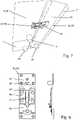
- the first mounting device 15 comprises an angled part 19 with a Z-shaped profile having a web portion 21, a first flange portion 23, and a second flange portion 25.
- the angled part 19 is mounted to the inner surface 27 of the armrest member 7 facing the base member 3 and the opposite armrest member 7, in such a way that the web portion 21 extends away from the inner surface 27 of the armrest member 7 and the first flange portion 23 extends parallelly spaced from the inner surface 27 of the armrest member 7 by a gap 29.
- the angled part 19 is mounted to the armrest member 7 in such a way that the angled part 19 is slidable in parallel to the inner surface 27 of the armrest member 7 in the vertical direction between and upper position and a lower position.
- the angled part 19 is further mounted to the armrest member 7 in such a way that at least in the upper position the angled part 19 is rotatable relative to the armrest member 7 about an axis of rotation 28 perpendicular to the inner surface 27 of the armrest member 7 between a locking position and a release position.
- the first flange portion 23, and thus the gap 29, extends vertically downwards from the web portion 21 to receive an upper edge 31 of a lateral side of the base member 3 in the gap 29 between the first flange portion 23 and the inner surface 27 of the armrest member 7.
- the first flange portion 23, and thus the gap 29 extends sidewards or upwards, i.e. not downwards, from the web portion 21 to release the upper edge 31 of the lateral side of the base member 3 from the gap 29, so that the armrest member 7 can be moved away from the base member 3 at the first mounting device 15.
- the second flange portion 25 is arranged in parallel to the first flange portion 23 at the end of the web portion 21 opposite from the first flange portion 23.
- the second flange portion 25 is mounted to the inner surface 27 of the armrest member 7 by a pin 33 extending perpendicularly from the inner surface 27 of the armrest member 7 and engaging with a hole 35 in the second flange portion 25.
- the hole 35 is in the form of a slotted hole with a longitudinal extension in the vertical direction, so that the second flange portion 25, and thus the entire angled part 19, can be slid relative to the pin 33 guided along the slotted hole. As particularly visible in Fig.
- the hole 35 has a key-hole shape with a slot portion 37 at the upper end and a round portion 41 at the lower end.
- the pin 33 has a square-shaped cross section, having at least two different diameters including a greater diameter in a diagonal direction, i.e. from one corner to the opposite corner, and a smaller diameter in a main direction parallel to a side and connecting two opposite sides of the square-shaped cross section.
- the hole 35 and the pin 33 are formed such that the width of the slot portion 37 is greater than the smaller diameter but smaller than the greater diameter of the pin 33, so that the pin 33 fits in the slot portion 37 along the smaller diameter but not along the greater diameter and cannot be rotated in the slot portion 37.
- the diameter of the round portion 41 is greater than the greater diameter of the pin 33, so that the pin 33 can be rotated in the round portion 41. In such a way, the pin 33 cannot be rotated relative to the angled part 19 as long as it is in the upper position in the slot portion 37, but can be rotated relative to the angled part 19 when it is in the lower position in the round portion 41.
- the pin 33 is mounted to the inner surface 27 of the armrest member 7 by a mounting plate 47 on which the pin 33 is formed and which is fixed to the inner surface 27 of the armrest member 7 by screws 49.
- the gap 29 to receive the upper edge 31 of the base member 3 is formed between the mounting plate 47 and the first flange portion 23.
- the pin 33 has a mushroom shape with an extended-diameter head 51 at its free end to secure the pin 33 in the hole 35 and prevent it from slipping out of the hole 35.
- the second mounting device 17 includes a latching connection 53 in the form of a ratchet connection.
- the second mounting device 17 includes a crocodile clip mechanism 55 comprising a first part 57 mounted to the bottom side 59 of the base member 3 and a second part 61 mounted to the bottom side 63 of the armrest member 7 and engaging the first part 57.
- the first part 57 includes a latch pin 65 having a triangular cross section and extending vertically downwards.
- the second part 61 includes two opposite toothed latch elements 69 in the form of rods with teeth 71 at one longitudinal side, biased towards each other and engaging the latch pin 65 from opposite sides with their teeth 71, so that after engagement relative movement of the first and second parts 57, 61 in a first direction into further engagement is permitted, while relative movement of the first and second parts 57, 61 in the opposite second direction out of engagement is inhibited.
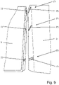
- the backrest member 5 is mounted to the base member 3 by three bayonet bracket mechanisms 73 spaced in the horizontal width direction of the seating furniture 1, each bayonet bracket mechanism 73 including a first bayonet bracket 75 mounted to the backrest member 5 and a second bayonet bracket 77 mounted to the base member 3. First and second bayonet brackets 75, 77 are engageable to one another in a sliding manner.
- the armrest member 7 comprises a floor support 79 configured for direct stand and support on the floor 13, as shown in Fig. 7 .
- the backrest member 5 comprises a floor support 83 configured for direct stand and support on the floor 13. In such a way, the armrest member 7 and the backrest member 5 carry their own weight and the bayonet bracket mechanisms 73 do not need to transfer vertical loads.
- first and second mounting devices 15, 17 are each brought into engagement.
- the angled part 19 is slid into the upper position and rotated into the release position.
- the armrest member 7 is positioned with its inner surface 27 against the lateral side of the base member 3, such that the upper edge 31 of the lateral side of the base member 3 is positioned below the angled part 19.
- the angled part 19 is rotated downwards into the locking position and subsequently slid downwards into the lower position, so that the upper edge 31 of the base member 3 is received in the gap 29, and the first flange portion 23 holds and secures the upper edge 31 and thus the entire base member 3 against the armrest member 7 in the horizontal width direction.
- the second mounting device 17 is engaged by latching a latching connection 53 to provide a further horizontal fixture of the armrest member 7 against the base member 3.
- first and second mounting devices 15, 17 are employed to mount the armrest member 7 to the base member 3, it is also possible and preferred to employ the first and second mounting devices 15, 17 to mount the backrest member 5 to the base member 3 to replace or complement the above described bayonet bracket mechanism 73. Further, the present invention might be transferred to the connection of two furniture components in general. Specifically, the seating furniture according to the invention as described above with the first and second mounting devices 15, 17 mounting the armrest member 7 to the base member 3, might also be transferred to a general furniture piece wherein the first and second mounting devices 15, 17 are employed to mount a first furniture component to a second furniture component.
Landscapes
- Engineering & Computer Science (AREA)
- General Engineering & Computer Science (AREA)
- Mechanical Engineering (AREA)
- Health & Medical Sciences (AREA)
- General Health & Medical Sciences (AREA)
- Nursing (AREA)
- Chair Legs, Seat Parts, And Backrests (AREA)
- Connection Of Plates (AREA)
Priority Applications (5)
| Application Number | Priority Date | Filing Date | Title |
|---|---|---|---|
| EP21154595.9A EP4035569A1 (fr) | 2021-02-01 | 2021-02-01 | Meuble d'assise |
| CN202210093785.6A CN114831455A (zh) | 2021-02-01 | 2022-01-26 | 座椅家具 |
| CA3147144A CA3147144A1 (fr) | 2021-02-01 | 2022-01-31 | Mobilier de siege |
| JP2022013178A JP2022117970A (ja) | 2021-02-01 | 2022-01-31 | 座席家具 |
| US17/588,410 US11766128B2 (en) | 2021-02-01 | 2022-01-31 | Seating furniture |
Applications Claiming Priority (1)
| Application Number | Priority Date | Filing Date | Title |
|---|---|---|---|
| EP21154595.9A EP4035569A1 (fr) | 2021-02-01 | 2021-02-01 | Meuble d'assise |
Publications (1)
| Publication Number | Publication Date |
|---|---|
| EP4035569A1 true EP4035569A1 (fr) | 2022-08-03 |
Family
ID=74494823
Family Applications (1)
| Application Number | Title | Priority Date | Filing Date |
|---|---|---|---|
| EP21154595.9A Withdrawn EP4035569A1 (fr) | 2021-02-01 | 2021-02-01 | Meuble d'assise |
Country Status (5)
| Country | Link |
|---|---|
| US (1) | US11766128B2 (fr) |
| EP (1) | EP4035569A1 (fr) |
| JP (1) | JP2022117970A (fr) |
| CN (1) | CN114831455A (fr) |
| CA (1) | CA3147144A1 (fr) |
Families Citing this family (7)
| Publication number | Priority date | Publication date | Assignee | Title |
|---|---|---|---|---|
| SE543531C2 (en) * | 2018-10-01 | 2021-03-23 | Ikea Supply Ag | Seat clip, chair comprising seat clip and method for assembling a chair |
| US12082705B2 (en) * | 2021-08-06 | 2024-09-10 | Flexsteel Industries, Inc. | Modular furniture assembly and associated method of assembly |
| CN216984254U (zh) * | 2022-01-06 | 2022-07-19 | 宋同佩 | 一种模块组合沙发 |
| US20230407898A1 (en) * | 2022-05-18 | 2023-12-21 | Rongwei CAI | Rattan-weaved furniture interlocking mechanism |
| USD984877S1 (en) * | 2022-12-13 | 2023-05-02 | Shenzhen Exquisite Youth Technology Co., Ltd. | Sofa connector |
| CN116725335B (zh) * | 2023-07-03 | 2025-12-30 | 永艺家具股份有限公司 | 一种扶手快捷装配方法 |
| US12532968B1 (en) * | 2025-06-27 | 2026-01-27 | Wenhe Peng | Sofa |
Citations (4)
| Publication number | Priority date | Publication date | Assignee | Title |
|---|---|---|---|---|
| GB440660A (en) * | 1935-06-11 | 1936-01-03 | Albert William Whitehouse | Improvements in or relating to bedstead or other fittings |
| AT292247B (de) * | 1970-03-03 | 1971-08-25 | Hasag Haslberger K G Moebelfab | Gepolstertes Sitzmöbel mit abnehmbaren Armlehnen |
| US4365840A (en) * | 1980-10-30 | 1982-12-28 | Coach & Car Equipment Corporation | Seat with back cushion attachment |
| CA2402583A1 (fr) * | 2001-09-25 | 2003-03-25 | Michael R. Mero, Jr. | Appareil de fixation de sections independantes d'un meuble-siege modulaire |
Family Cites Families (8)
| Publication number | Priority date | Publication date | Assignee | Title |
|---|---|---|---|---|
| US3013839A (en) * | 1959-12-02 | 1961-12-19 | Lu Van Inc | Chair arm construction |
| US4023860A (en) * | 1976-07-26 | 1977-05-17 | Coach & Car Equipment Corporation | Seat back with limited access to the rear thereof |
| US6959852B2 (en) | 2003-09-29 | 2005-11-01 | Ethicon Endo-Surgery, Inc. | Surgical stapling instrument with multistroke firing incorporating an anti-backup mechanism |
| US20200375362A1 (en) * | 2019-05-29 | 2020-12-03 | Williams-Sonoma, Inc. | Knock Down Furniture Construction |
| US20210068547A1 (en) * | 2019-09-06 | 2021-03-11 | Overman International Corporation | Toolless Assembly Method for Upholstered Furniture |
| DE202020101720U1 (de) * | 2019-12-23 | 2020-05-18 | Werner Polstertechnik Gmbh | Zerlegbares Möbel |
| US12016461B2 (en) * | 2020-03-08 | 2024-06-25 | Zinus Inc. | Compactly packageable sofa with a zippered flap between the seat cushion and the seat back |
| CN212117653U (zh) * | 2020-03-19 | 2020-12-11 | 锐迈机械科技(吴江)有限公司 | 一种沙发扶手连接结构及沙发组件 |
-
2021
- 2021-02-01 EP EP21154595.9A patent/EP4035569A1/fr not_active Withdrawn
-
2022
- 2022-01-26 CN CN202210093785.6A patent/CN114831455A/zh active Pending
- 2022-01-31 CA CA3147144A patent/CA3147144A1/fr active Pending
- 2022-01-31 JP JP2022013178A patent/JP2022117970A/ja active Pending
- 2022-01-31 US US17/588,410 patent/US11766128B2/en active Active
Patent Citations (4)
| Publication number | Priority date | Publication date | Assignee | Title |
|---|---|---|---|---|
| GB440660A (en) * | 1935-06-11 | 1936-01-03 | Albert William Whitehouse | Improvements in or relating to bedstead or other fittings |
| AT292247B (de) * | 1970-03-03 | 1971-08-25 | Hasag Haslberger K G Moebelfab | Gepolstertes Sitzmöbel mit abnehmbaren Armlehnen |
| US4365840A (en) * | 1980-10-30 | 1982-12-28 | Coach & Car Equipment Corporation | Seat with back cushion attachment |
| CA2402583A1 (fr) * | 2001-09-25 | 2003-03-25 | Michael R. Mero, Jr. | Appareil de fixation de sections independantes d'un meuble-siege modulaire |
Also Published As
| Publication number | Publication date |
|---|---|
| JP2022117970A (ja) | 2022-08-12 |
| US11766128B2 (en) | 2023-09-26 |
| CA3147144A1 (fr) | 2022-08-01 |
| CN114831455A (zh) | 2022-08-02 |
| US20220240678A1 (en) | 2022-08-04 |
Similar Documents
| Publication | Publication Date | Title |
|---|---|---|
| EP4035569A1 (fr) | Meuble d'assise | |
| US6431090B1 (en) | Adjustable shelving with tiltable shelves | |
| CA2633297C (fr) | Systeme d'entreposage avec traverse(s) d'installation | |
| NO319472B1 (no) | System for avtagbart oppheng av hyller, skuffer eller lignende | |
| EP3513684A1 (fr) | Petite base pour un système modulaire d'affichage au détail | |
| CA2598874A1 (fr) | Banc pour enfants | |
| US3494661A (en) | Clip-on tray | |
| JP6490484B2 (ja) | ヘッドボードおよびベッド | |
| JP5701051B2 (ja) | カウンターにおけるハイユニットと可動仕切パネルの固定装置 | |
| JP7064380B2 (ja) | 天板付き什器 | |
| US3263294A (en) | Support | |
| JP2019080612A (ja) | 椅子 | |
| JP7126258B2 (ja) | ブラケット、商品陳列棚装置及びブラケットの取り付け方法 | |
| JP5334628B2 (ja) | パネル装置 | |
| JP7184234B2 (ja) | デスクシステム | |
| JP4806752B2 (ja) | 天板付家具 | |
| JP3568740B2 (ja) | ベッド装置 | |
| JP3169044U (ja) | カーテンレールの取付ブラケット | |
| JP2004313471A (ja) | 連結デスク等における仕切パネルの取付構造 | |
| JP2020192238A (ja) | 陳列棚へのパネルの取付構造 | |
| JPS63114Y2 (fr) | ||
| JP5262832B2 (ja) | デスク用パネルの取付構造 | |
| JP2009261841A5 (fr) | ||
| GB2432306A (en) | Fastening plate for seat or table leg mounting | |
| JP5512333B2 (ja) | 付加部材の取付構造および什器 |
Legal Events
| Date | Code | Title | Description |
|---|---|---|---|
| PUAI | Public reference made under article 153(3) epc to a published international application that has entered the european phase |
Free format text: ORIGINAL CODE: 0009012 |
|
| STAA | Information on the status of an ep patent application or granted ep patent |
Free format text: STATUS: THE APPLICATION HAS BEEN PUBLISHED |
|
| AK | Designated contracting states |
Kind code of ref document: A1 Designated state(s): AL AT BE BG CH CY CZ DE DK EE ES FI FR GB GR HR HU IE IS IT LI LT LU LV MC MK MT NL NO PL PT RO RS SE SI SK SM TR |
|
| STAA | Information on the status of an ep patent application or granted ep patent |
Free format text: STATUS: THE APPLICATION IS DEEMED TO BE WITHDRAWN |
|
| STAA | Information on the status of an ep patent application or granted ep patent |
Free format text: STATUS: THE APPLICATION HAS BEEN PUBLISHED |
|
| 18D | Application deemed to be withdrawn |
Effective date: 20230204 |
|
| 19U | Interruption of proceedings before grant |
Effective date: 20230110 |
|
| D18D | Application deemed to be withdrawn (deleted) | ||
| 19W | Proceedings resumed before grant after interruption of proceedings |
Effective date: 20240201 |
|
| STAA | Information on the status of an ep patent application or granted ep patent |
Free format text: STATUS: REQUEST FOR EXAMINATION WAS MADE |
|
| 17P | Request for examination filed |
Effective date: 20240129 |
|
| RAP3 | Party data changed (applicant data changed or rights of an application transferred) |
Owner name: SNUG FURNITURE LTD. |
|
| RBV | Designated contracting states (corrected) |
Designated state(s): AL AT BE BG CH CY CZ DE DK EE ES FI FR GB GR HR HU IE IS IT LI LT LU LV MC MK MT NL NO PL PT RO RS SE SI SK SM TR |
|
| STAA | Information on the status of an ep patent application or granted ep patent |
Free format text: STATUS: EXAMINATION IS IN PROGRESS |
|
| 17Q | First examination report despatched |
Effective date: 20240621 |
|
| 17Q | First examination report despatched |
Effective date: 20240626 |
|
| STAA | Information on the status of an ep patent application or granted ep patent |
Free format text: STATUS: THE APPLICATION IS DEEMED TO BE WITHDRAWN |
|
| 18D | Application deemed to be withdrawn |
Effective date: 20250103 |