EP4035719A1 - Ventil, insbesondere für eine vorrichtung zur verabreichung eines flüssigen medikaments, sowie eine entsprechende vorrichtung zur verabreichung eines flüssigen medikaments - Google Patents
Ventil, insbesondere für eine vorrichtung zur verabreichung eines flüssigen medikaments, sowie eine entsprechende vorrichtung zur verabreichung eines flüssigen medikaments Download PDFInfo
- Publication number
- EP4035719A1 EP4035719A1 EP22155423.1A EP22155423A EP4035719A1 EP 4035719 A1 EP4035719 A1 EP 4035719A1 EP 22155423 A EP22155423 A EP 22155423A EP 4035719 A1 EP4035719 A1 EP 4035719A1
- Authority
- EP
- European Patent Office
- Prior art keywords
- liquid
- valve according
- valve
- valve body
- delimiting elements
- Prior art date
- Legal status (The legal status is an assumption and is not a legal conclusion. Google has not performed a legal analysis and makes no representation as to the accuracy of the status listed.)
- Granted
Links
Images

Classifications
-
- F—MECHANICAL ENGINEERING; LIGHTING; HEATING; WEAPONS; BLASTING
- F16—ENGINEERING ELEMENTS AND UNITS; GENERAL MEASURES FOR PRODUCING AND MAINTAINING EFFECTIVE FUNCTIONING OF MACHINES OR INSTALLATIONS; THERMAL INSULATION IN GENERAL
- F16K—VALVES; TAPS; COCKS; ACTUATING-FLOATS; DEVICES FOR VENTING OR AERATING
- F16K31/00—Actuating devices; Operating means; Releasing devices
- F16K31/12—Actuating devices; Operating means; Releasing devices actuated by fluid
-
- A—HUMAN NECESSITIES
- A61—MEDICAL OR VETERINARY SCIENCE; HYGIENE
- A61M—DEVICES FOR INTRODUCING MEDIA INTO, OR ONTO, THE BODY; DEVICES FOR TRANSDUCING BODY MEDIA OR FOR TAKING MEDIA FROM THE BODY; DEVICES FOR PRODUCING OR ENDING SLEEP OR STUPOR
- A61M11/00—Sprayers or atomisers specially adapted for therapeutic purposes
- A61M11/006—Sprayers or atomisers specially adapted for therapeutic purposes operated by applying mechanical pressure to the liquid to be sprayed or atomised
- A61M11/007—Syringe-type or piston-type sprayers or atomisers
-
- A—HUMAN NECESSITIES
- A61—MEDICAL OR VETERINARY SCIENCE; HYGIENE
- A61M—DEVICES FOR INTRODUCING MEDIA INTO, OR ONTO, THE BODY; DEVICES FOR TRANSDUCING BODY MEDIA OR FOR TAKING MEDIA FROM THE BODY; DEVICES FOR PRODUCING OR ENDING SLEEP OR STUPOR
- A61M16/00—Devices for influencing the respiratory system of patients by gas treatment, e.g. ventilators; Tracheal tubes
- A61M16/20—Valves specially adapted to medical respiratory devices
- A61M16/208—Non-controlled one-way valves, e.g. exhalation, check, pop-off non-rebreathing valves
-
- A—HUMAN NECESSITIES
- A61—MEDICAL OR VETERINARY SCIENCE; HYGIENE
- A61M—DEVICES FOR INTRODUCING MEDIA INTO, OR ONTO, THE BODY; DEVICES FOR TRANSDUCING BODY MEDIA OR FOR TAKING MEDIA FROM THE BODY; DEVICES FOR PRODUCING OR ENDING SLEEP OR STUPOR
- A61M39/00—Tubes, tube connectors, tube couplings, valves, access sites or the like, specially adapted for medical use
- A61M39/22—Valves or arrangement of valves
- A61M39/24—Check- or non-return valves
-
- A—HUMAN NECESSITIES
- A61—MEDICAL OR VETERINARY SCIENCE; HYGIENE
- A61M—DEVICES FOR INTRODUCING MEDIA INTO, OR ONTO, THE BODY; DEVICES FOR TRANSDUCING BODY MEDIA OR FOR TAKING MEDIA FROM THE BODY; DEVICES FOR PRODUCING OR ENDING SLEEP OR STUPOR
- A61M5/00—Devices for bringing media into the body in a subcutaneous, intra-vascular or intramuscular way; Accessories therefor, e.g. filling or cleaning devices, arm-rests
- A61M5/14—Infusion devices, e.g. infusing by gravity; Blood infusion; Accessories therefor
- A61M5/168—Means for controlling media flow to the body or for metering media to the body, e.g. drip meters, counters ; Monitoring media flow to the body
- A61M5/16877—Adjusting flow; Devices for setting a flow rate
- A61M5/16881—Regulating valves
-
- F—MECHANICAL ENGINEERING; LIGHTING; HEATING; WEAPONS; BLASTING
- F04—POSITIVE - DISPLACEMENT MACHINES FOR LIQUIDS; PUMPS FOR LIQUIDS OR ELASTIC FLUIDS
- F04B—POSITIVE-DISPLACEMENT MACHINES FOR LIQUIDS; PUMPS
- F04B13/00—Pumps specially modified to deliver fixed or variable measured quantities
-
- F—MECHANICAL ENGINEERING; LIGHTING; HEATING; WEAPONS; BLASTING
- F04—POSITIVE - DISPLACEMENT MACHINES FOR LIQUIDS; PUMPS FOR LIQUIDS OR ELASTIC FLUIDS
- F04B—POSITIVE-DISPLACEMENT MACHINES FOR LIQUIDS; PUMPS
- F04B19/00—Machines or pumps having pertinent characteristics not provided for in, or of interest apart from, groups F04B1/00 - F04B17/00
- F04B19/006—Micropumps
-
- F—MECHANICAL ENGINEERING; LIGHTING; HEATING; WEAPONS; BLASTING
- F04—POSITIVE - DISPLACEMENT MACHINES FOR LIQUIDS; PUMPS FOR LIQUIDS OR ELASTIC FLUIDS
- F04B—POSITIVE-DISPLACEMENT MACHINES FOR LIQUIDS; PUMPS
- F04B23/00—Pumping installations or systems
- F04B23/02—Pumping installations or systems having reservoirs
-
- F—MECHANICAL ENGINEERING; LIGHTING; HEATING; WEAPONS; BLASTING
- F04—POSITIVE - DISPLACEMENT MACHINES FOR LIQUIDS; PUMPS FOR LIQUIDS OR ELASTIC FLUIDS
- F04B—POSITIVE-DISPLACEMENT MACHINES FOR LIQUIDS; PUMPS
- F04B53/00—Component parts, details or accessories not provided for in, or of interest apart from, groups F04B1/00 - F04B23/00 or F04B39/00 - F04B47/00
- F04B53/10—Valves; Arrangement of valves
-
- F—MECHANICAL ENGINEERING; LIGHTING; HEATING; WEAPONS; BLASTING
- F16—ENGINEERING ELEMENTS AND UNITS; GENERAL MEASURES FOR PRODUCING AND MAINTAINING EFFECTIVE FUNCTIONING OF MACHINES OR INSTALLATIONS; THERMAL INSULATION IN GENERAL
- F16K—VALVES; TAPS; COCKS; ACTUATING-FLOATS; DEVICES FOR VENTING OR AERATING
- F16K27/00—Construction of housing; Use of materials therefor
-
- F—MECHANICAL ENGINEERING; LIGHTING; HEATING; WEAPONS; BLASTING
- F16—ENGINEERING ELEMENTS AND UNITS; GENERAL MEASURES FOR PRODUCING AND MAINTAINING EFFECTIVE FUNCTIONING OF MACHINES OR INSTALLATIONS; THERMAL INSULATION IN GENERAL
- F16K—VALVES; TAPS; COCKS; ACTUATING-FLOATS; DEVICES FOR VENTING OR AERATING
- F16K99/00—Subject matter not provided for in other groups of this subclass
- F16K99/0001—Microvalves
- F16K99/0003—Constructional types of microvalves; Details of the cutting-off member
- F16K99/0021—No-moving-parts valves
-
- F—MECHANICAL ENGINEERING; LIGHTING; HEATING; WEAPONS; BLASTING
- F16—ENGINEERING ELEMENTS AND UNITS; GENERAL MEASURES FOR PRODUCING AND MAINTAINING EFFECTIVE FUNCTIONING OF MACHINES OR INSTALLATIONS; THERMAL INSULATION IN GENERAL
- F16K—VALVES; TAPS; COCKS; ACTUATING-FLOATS; DEVICES FOR VENTING OR AERATING
- F16K99/00—Subject matter not provided for in other groups of this subclass
- F16K99/0001—Microvalves
- F16K99/0034—Operating means specially adapted for microvalves
- F16K99/0055—Operating means specially adapted for microvalves actuated by fluids
- F16K99/0057—Operating means specially adapted for microvalves actuated by fluids the fluid being the circulating fluid itself, e.g. check valves
-
- A—HUMAN NECESSITIES
- A61—MEDICAL OR VETERINARY SCIENCE; HYGIENE
- A61M—DEVICES FOR INTRODUCING MEDIA INTO, OR ONTO, THE BODY; DEVICES FOR TRANSDUCING BODY MEDIA OR FOR TAKING MEDIA FROM THE BODY; DEVICES FOR PRODUCING OR ENDING SLEEP OR STUPOR
- A61M11/00—Sprayers or atomisers specially adapted for therapeutic purposes
-
- A—HUMAN NECESSITIES
- A61—MEDICAL OR VETERINARY SCIENCE; HYGIENE
- A61M—DEVICES FOR INTRODUCING MEDIA INTO, OR ONTO, THE BODY; DEVICES FOR TRANSDUCING BODY MEDIA OR FOR TAKING MEDIA FROM THE BODY; DEVICES FOR PRODUCING OR ENDING SLEEP OR STUPOR
- A61M39/00—Tubes, tube connectors, tube couplings, valves, access sites or the like, specially adapted for medical use
- A61M39/22—Valves or arrangement of valves
- A61M39/24—Check- or non-return valves
- A61M2039/2493—Check valve with complex design, e.g. several inlets and outlets and several check valves in one body
-
- A—HUMAN NECESSITIES
- A61—MEDICAL OR VETERINARY SCIENCE; HYGIENE
- A61M—DEVICES FOR INTRODUCING MEDIA INTO, OR ONTO, THE BODY; DEVICES FOR TRANSDUCING BODY MEDIA OR FOR TAKING MEDIA FROM THE BODY; DEVICES FOR PRODUCING OR ENDING SLEEP OR STUPOR
- A61M2202/00—Special media to be introduced, removed or treated
- A61M2202/04—Liquids
- A61M2202/0468—Liquids non-physiological
-
- B—PERFORMING OPERATIONS; TRANSPORTING
- B01—PHYSICAL OR CHEMICAL PROCESSES OR APPARATUS IN GENERAL
- B01L—CHEMICAL OR PHYSICAL LABORATORY APPARATUS FOR GENERAL USE
- B01L3/00—Containers or dishes for laboratory use, e.g. laboratory glassware; Droppers
- B01L3/50—Containers for the purpose of retaining a material to be analysed, e.g. test tubes
- B01L3/502—Containers for the purpose of retaining a material to be analysed, e.g. test tubes with fluid transport, e.g. in multi-compartment structures
- B01L3/5027—Containers for the purpose of retaining a material to be analysed, e.g. test tubes with fluid transport, e.g. in multi-compartment structures by integrated microfluidic structures, i.e. dimensions of channels and chambers are such that surface tension forces are important, e.g. lab-on-a-chip
- B01L3/502738—Containers for the purpose of retaining a material to be analysed, e.g. test tubes with fluid transport, e.g. in multi-compartment structures by integrated microfluidic structures, i.e. dimensions of channels and chambers are such that surface tension forces are important, e.g. lab-on-a-chip characterised by integrated valves
Definitions
- the invention relates to a valve, in particular for a device for administering a liquid medicament, and a corresponding device for administering a liquid medicament.
- Devices for administering a liquid medication are known from the prior art, which devices have a reservoir which is connected to a pump system.
- the outlet side of the pump is connected to a drug outlet, such as a tube or hose, or to a nebulizer.
- the pump chamber of the pump often has an inlet valve and an outlet valve.
- the inlet valve closes the pump chamber just as the pump is creating dispensing pressure to deliver medication through the tube, tubing, or nebulizer to prevent back flow of medication into the reservoir.
- a negative pressure is created in the pump chamber, causing the drug to flow from the reservoir into the pump chamber through the opening inlet valve, while the outlet valve closes to prevent back flow of drug out of the tube, hose, or nebulizer.
- the valves are thus designed as common one-way valves, for example as check valves. Similar devices describe the WO 2013/191011 A1 , the US 8,628,517 B2 and the WO 2013/072790 A1 .
- the device for administering the liquid medicament In medical applications in particular, it is often desirable for the device for administering the liquid medicament to be as small as possible and thus take up little space.
- the intake and exhaust valves known from the prior art which are usually purely mechanical, cannot be reduced indefinitely, so that there is a need to further improve such valves, or possibly even to make them completely superfluous.
- the valve according to the invention has a valve body which includes an interior space for receiving a liquid, in particular a liquid medication.
- the valve body has a liquid inlet and an opposite liquid outlet, both of which open into the interior.
- a multiplicity of microchannels are arranged in the interior space and extend in the direction of connection between the liquid inlet and the liquid outlet.
- the valve according to the invention makes use of the capillary effect. It is known that liquids can wet surfaces and move through complex structures due to capillary forces. The energy required for the movement of the liquid is determined by the difference in the atomic forces of attraction between the liquid atoms in the interior of the liquid and the atomic forces of attraction between the liquid atoms, which are on the liquid surface and thus on the interface between the liquid and a gas. The interface between a liquid and a gas is also called the free surface. Likewise, energy must be expended for the removal of liquid atoms from the free surface, so that atoms that were previously lying deeper inside the liquid form the free surface. A force must therefore be applied in order to remove liquid components from heavily wetting surfaces.
- the valve body forms a liquid channel delimited by side walls.
- the side walls can be parallel side walls of a channel which is polygonal or round in cross-section, for example circular.
- the interior has a cross-sectional area that is larger than a cross-sectional area of the microchannels, wherein a cross-sectional area ratio between the microchannels and the interior is preferably between 1:5 and 1:1000 and more preferably between 1:50 and 1:100.
- the microchannels preferably have a diameter between 1 ⁇ m and 200 ⁇ m and particularly preferably between 5 ⁇ m and 20 ⁇ m.
- the microchannels are formed by a lattice of parallel, rod-shaped delimiting elements, or by a plurality of parallel, mutually offset layers of a lattice of parallel, rod-shaped delimiting elements.
- the delimiting elements can extend perpendicular to the direction of connection between the liquid inlet and the liquid outlet.
- the delimiting elements preferably have a round, in particular circular, or a polygonal cross section.
- the delimiting elements can, for example, have a diameter between 0.5 ⁇ m and 50 ⁇ m, preferably between 3 ⁇ m and 15 ⁇ m.
- the length of the limiting elements can be from a few ⁇ m to the full diameter of the interior of the valve body, the length of the limiting elements is particularly preferably between 20% and 80% of the interior diameter perpendicular to the direction of connection between liquid inlet and liquid outlet.
- the delimiting elements can extend, starting from an inside of the side wall delimiting the interior of the valve body, in the direction of an opposite side wall without reaching it, so that a distance is formed between the delimiting elements and the respectively opposite side wall.
- This embodiment is also characterized in particular by the fact that it is easy to manufacture.
- one embodiment of the invention provides that the surface of the delimiting elements has a functional coating, for example a hydrophilic coating.
- the inside of the channel can also be hydrophobically coated.
- the interior space, the liquid inlet and the liquid outlet have the same cross-sectional geometry perpendicular to the direction of connection. This achieves a particularly compact valve geometry that is easy to produce.
- valve body has parallel side walls, the inner sides of which delimit the interior space, with the side walls opening into the liquid inlet or the liquid outlet at opposite ends.
- a valve that is easy to produce is achieved in that, in the last-mentioned embodiment, the valve body has a constant cross section over its entire length between the liquid inlet and the liquid outlet.
- the valve body can have a round, in particular circular, or a polygonal cross section.
- the invention relates to a device for administering a liquid medicament, with a reservoir in which a medicament is held or can be held, and with a pump which has a pump chamber which has a permeable only in the direction from the reservoir into the pump chamber
- a pump which has a pump chamber which has a permeable only in the direction from the reservoir into the pump chamber
- One-way valve fluidly connected to the reservoir, and fluidly connected to a medication outlet via a valve according to any one of the preceding claims.
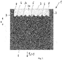
- valve body 1 is shown in longitudinal cross section.
- the valve body 1 is delimited by opposite parallel side walls 7 . With their inner sides 8, the side walls 7 delimit an interior space 2 in which a liquid 20, for example a medication, is accommodated.
- a liquid inlet 3 and a liquid outlet 4 are formed on opposite sides of the valve body 1 .
- the liquid inlet 3 and the liquid outlet 4 lying opposite have exactly the same cross section as the rest of the valve body 1 , in particular as the interior space 2 .
- a pump with a pump chamber of a device for administering a liquid medication can be connected to the liquid outlet 4 .
- the valve body 1 can have a circular cross-section, for example, or a polygonal, for example a rectangular and in particular a square one.
- the delimiting elements 6 shown in cross section are rod-shaped lattice struts which extend parallel to one another and extend perpendicularly to the plane of the drawing. Each two adjacent delimiting elements 6 form a microchannel 5 between them, which extends in the connecting direction x between the Liquid inlet 3 and the liquid outlet 4 extends and is open to both inlets 3, 4 out.
- the microchannels are formed by a plurality of parallel, mutually offset layers of a grid of parallel, rod-shaped delimiting elements.
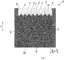
- the liquid 20 forms, as in figure 1 as shown, has a substantially planar free surface between itself and the gas 30.
- the radius of curvature of the free surface depends on the so-called Laplace pressure. This pressure increases with decreasing interface radius. Therefore, if the negative pressure for the in the Figures 1 to 3 shown microchannel structure exceeds the valid maximum Laplacian pressure, the liquid is transported out of the valve body 1.
- the valve according to the invention is therefore particularly suitable for use as an outlet valve in a generic device for administering a liquid medication.
- the Laplacian pressure increases proportionally to the surface tension of the liquid. Therefore, in order to adjust the threshold value for the negative pressure at which the liquid is transported out of the valve body 1 to a specific value with a given surface tension, it may be necessary to adjust the diameter of the microchannels 5, and thus the distance between the limiting elements 6, accordingly.
- the in the Figures 1 to 3 can, for example, have an interior diameter perpendicular to the inner sides 8 of the side walls of between approximately 1 ⁇ m and 500 ⁇ m. This diameter is preferably between 10 ⁇ m and 100 ⁇ m.
- the diameter of the microchannels 5, and therefore the free distance or the clear dimension between the delimiting elements 6, can be between 0.5 and 50 ⁇ m.
- the free distance or the clearance between the delimiting elements 6 is preferably between 3 and 15 ⁇ m.
- the valve according to the invention has the advantage that the required structures can be produced using common microstructuring methods, for example using micro-injection molding or silicon etching methods.
Landscapes
- Engineering & Computer Science (AREA)
- Health & Medical Sciences (AREA)
- General Engineering & Computer Science (AREA)
- Mechanical Engineering (AREA)
- Heart & Thoracic Surgery (AREA)
- Hematology (AREA)
- Biomedical Technology (AREA)
- Life Sciences & Earth Sciences (AREA)
- Animal Behavior & Ethology (AREA)
- General Health & Medical Sciences (AREA)
- Public Health (AREA)
- Veterinary Medicine (AREA)
- Anesthesiology (AREA)
- Pulmonology (AREA)
- Dispersion Chemistry (AREA)
- Chemical & Material Sciences (AREA)
- Emergency Medicine (AREA)
- Physics & Mathematics (AREA)
- Fluid Mechanics (AREA)
- Vascular Medicine (AREA)
- Infusion, Injection, And Reservoir Apparatuses (AREA)
- Check Valves (AREA)
- Valve Housings (AREA)
- Micromachines (AREA)
- Multiple-Way Valves (AREA)
- Lift Valve (AREA)
Abstract
Description
- Die Erfindung betrifft ein Ventil, insbesondere für eine Vorrichtung zur Verabreichung eines flüssigen Medikaments, sowie eine entsprechende Vorrichtung zur Verabreichung eines flüssigen Medikaments.
- Aus dem Stand der Technik sind Vorrichtungen zur Verabreichung eines flüssigen Medikaments bekannt, welche ein Reservoir aufweisen, das mit einem Pumpensystem verbunden ist. Die Auslassseite der Pumpe ist mit einem Medikamentenauslass verbunden, beispielsweise mit einem Rohr oder Schlauch, oder mit einem Zerstäuber. Häufig weist die Pumpenkammer der Pumpe ein Einlass- und ein Auslassventil auf. Das Einlassventil verschließt die Pumpenkammer genau dann, wenn die Pumpe einen Ausgabedruck zur Bereitstellung des Medikaments über das Rohr, den Schlauch, oder den Zerstäuber erzeugt, um ein Zurückfließen des Medikaments in das Reservoir zu vermeiden. Für das Wiederauffüllen der Pumpenkammer wird in der Pumpenkammer ein Unterdruck erzeugt, wodurch das Medikament aus dem Reservoir durch das sich öffnende Einlassventil in die Pumpenkammer fließt, während das Auslassventil schließt, um ein Zurückfließen des Medikaments aus dem Rohr, Schlauch, oder Zerstäuber zu vermeiden. Die Ventile sind somit als gängige Einwegventile, beispielsweise als Rückschlagventile, ausgebildet. Ähnliche Vorrichtungen beschreiben die
WO 2013/191011 A1 , dieUS 8,628,517 B2 und dieWO 2013/072790 A1 . - Insbesondere bei medizinischen Anwendungen ist es häufig wünschenswert, dass die Vorrichtung zur Verabreichung des flüssigen Medikaments möglichst klein baut und somit wenig Platz einnimmt. Insbesondere die aus dem Stand der Technik bekannten, üblicherweise rein mechanischen Einlass- und Auslassventile können jedoch nicht unbeschränkt verkleinert werden, so dass Bedarf danach besteht, derartige Ventile noch weiter zu verbessern, oder sie gegebenenfalls sogar ganz überflüssig zu machen.
- Es ist daher die Aufgabe der Erfindung, ein gattungsgemäßes Ventil und eine entsprechende Vorrichtung zur Verabreichung eines flüssigen Medikaments vorzuschlagen, welche möglichstgeringe Abmessungenaufweisen.
- Diese Aufgabe wird erfindungsgemäß durch ein Ventil mit den Merkmalen des Patentanspruchs 1 gelöst. Der nebengeordnete Patentanspruch 12 betrifft eine entsprechende Vorrichtung zur Verabreichung eines flüssigen Medikaments. Die abhängigen Ansprüche 2 bis 9 betreffen jeweils vorteilhafte Ausführungsformen der Erfindung.
- Das erfindungsgemäße Ventil weist einen Ventilkörper auf, der einen Innenraum zur Aufnahme einer Flüssigkeit, insbesondere eines flüssigen Medikaments, umfasst. Der Ventilkörper weist einen Flüssigkeitseinlass und einen gegenüberliegenden Flüssigkeitsauslass auf, die beide in den Innenraum münden. In dem Innenraum ist eine Vielzahl Mikrokanäle angeordnet, die sich in Verbindungsrichtung zwischen dem Flüssigkeitseinlass und dem Flüssigkeitsauslass erstrecken.
- Das erfindungsgemäße Ventil macht sich den Kapillareffekt zunutze. Es ist bekannt, dass Flüssigkeiten aufgrund von Kapillarkräften Oberflächen benetzen und durch komplexe Strukturen hindurchbewegen können. Die für die Flüssigkeitsbewegung erforderliche Energie wird dabei durch den Unterschied der atomaren Anziehungskräfte zwischen den Flüssigkeitsatomen im Flüssigkeitsinneren und den atomaren Anziehungskräften zwischen den Flüssigkeitsatomen, welche sich an der Flüssigkeitsoberfläche und damit an der Grenzfläche zwischen der Flüssigkeit und einem Gas befinden. Die Grenzfläche zwischen einer Flüssigkeit und einem Gas wird auch als freie Oberfläche bezeichnet. Ebenso muss für die Entfernung von Flüssigkeitsatomen aus der freien Oberfläche Energie aufgewendet werden, so dass vormals tiefer liegende, sich im Flüssigkeitsinneren befindliche Atome die freie Oberfläche bilden. Es muss daher eine Kraft aufgewendet werden, um Flüssigkeitsanteile von stark benetzenden Oberflächen zu entfernen.
- Bei einer Ausführungsform der Erfindung bildet der Ventilkörper einen Flüssigkeitskanal, der von Seitenwänden begrenzt ist. Die Seitenwände können parallele Seitenwände eines im Querschnitt polygonalen oder runden, beispielsweise kreisrunden Kanals sein.
- Bei einer Ausführungsform weist der Innenraum eine Querschnittsfläche auf, die größer als eine Querschnittsfläche der Mikrokanäle ist, wobei ein Querschnittsflächenverhältnis zwischen den Mikrokanälen und dem Innenraum vorzugsweise zwischen 1:5 und 1:1000 und besonders bevorzugt zwischen 1:50 und 1:100 beträgt. Die Mikrokanäle weisen vorzugsweise einen Durchmesser zwischen 1 µm und 200 µm und besonders bevorzugt zwischen 5 µm und 20 µm auf.
- Bei einer Ausführungsform der Erfindung sind die Mikrokanäle von einem Gitter aus parallelen, stabförmigen Begrenzungselementen, oder von mehreren parallelen, zueinander versetzt angeordneten Lagen eines Gitters aus parallelen, stabförmigen Begrenzungselementen gebildet. Die Begrenzungselemente können sich dabei senkrecht zur Verbindungsrichtung zwischen dem Flüssigkeitseinlass und dem Flüssigkeitsauslass erstrecken. Die Begrenzungselemente weisen vorzugsweise eine runden, insbesondere kreisrunden, oder einen polygonalen Querschnitt auf. Die Begrenzungselemente können beispielsweise einen Durchmesser zwischen 0,5 µm und 50 µm,bevorzugt zwischen 3 µm und 15 µm aufweisen. Die Länge der Begrenzungselemente kann anbei von einigen µm bis zum vollen Durchmesser des Innenraums des Ventilkörpers betragen, besonders bevorzugt beträgt die Länge der Begrenzungselemente zwischen 20% und 80% des Innenraumdurchmessers senkrecht zur Verbindungsrichtung zwischen Flüssigkeitseinlass und Flüssigkeitsauslass. Dazu können sich die Begrenzungselemente ausgehend von einer Innenseite der den Innenraum des Ventilkörpers begrenzenden Seitenwand in Richtung einer gegenüberliegenden Seitenwand erstrecken, ohne diese zu erreichen, so dass ein Abstand zwischen den Begrenzungselementen und der jeweils gegenüberliegenden Seitenwand ausgebildet ist. Diese Ausführungsform zeichnet sich insbesondere auch dadurch aus, dass sie einfach in der Herstellung ist.
- Zur Erhöhung der Adhäsion zwischen den Begrenzungselementen und einer Flüssigkeit ist bei einer Ausführungsform der Erfindung vorgesehen, dass die Oberfläche der Begrenzungselemente eine funktionale Beschichtung, beispielsweise eine hydrophile Beschichtung, aufweist. Dazu kann weiterhin die Kanalinnenseite hydrophob beschichtet sein.
- Bei noch einer Ausführungsform der Erfindung weisen der Innenraum, der Flüssigkeitseinlass und der Flüssigkeitsauslass dieselbe Querschnittsgeometrie senkrecht zur Verbindungsrichtung auf. Dadurch wird eine besonders kompakte und einfach herstellbare Ventilgeometrie erreicht.
- Dabei kann vorgesehen sein, dass der Ventilkörper parallele Seitenwände aufweist, deren Innenseiten den Innenraum abgrenzen, wobei die Seitenwände an gegenüberliegenden Enden in den Flüssigkeitseinlass bzw. den Flüssigkeitsauslass münden. Ein einfach herstellbares Ventil wird dadurch erreicht, dass bei der zuletzt genannten Ausführungsform der Ventilkörper über seine gesamte Länge zwischen dem Flüssigkeitseinlass und dem Flüssigkeitsauslass einen konstanten Querschnitt aufweist.
- Der Ventilkörper kann einen runden, insbesondere kreisrunden, oder einen polygonalen Querschnitt aufweisen.
- Gemäß einem anderen Aspekt betrifft die Erfindung eine Vorrichtung zur Verabreichung eines flüssigen Medikaments, mit einem Reservoir, in dem ein Medikament vorgehalten oder vorhaltbar ist, und mit einer Pumpe, die eine Pumpenkammer aufweist, die über ein nur in Richtung vom Reservoir in die Pumpenkammer durchlässiges Einwegventil mit dem Reservoir fluidisch verbunden ist, und die über ein Ventil nach einem der vorangegangenen Ansprüche mit einem Medikamentenauslass fluidisch verbunden ist.
- Weitere Einzelheiten der Erfindung werden anhand der nachstehenden Figuren erläutert. Dabei zeigt:
- Figur 1
- einen schematischen Längsquerschnitt durch eine Ausführungsform des erfindungsgemäßen Ventils ohne angelegten Unterdruck;
- Figur 2
- einen schematischen Längsquerschnitt des Ventils gemäß
Figur 1 mit angelegtem Unterdruck P1 >O;und - Figur 3
- einen schematischen Längsquerschnitt des Ventils gemäß den
Figuren 1 und2 mit angelegtem Unterdruck P2 > P1• - Bei dem in
Figur 1 dargestellten Ventil ist der Ventilkörper 1 im Längsquerschnitt dargestellt. Der Ventilkörper 1 ist durch gegenüberliegende parallele Seitenwände 7 begrenzt. Die Seitenwände 7 begrenzen mit ihren Innenseiten 8 einen Innenraum 2, in dem eine Flüssigkeit 20, beispielsweise ein Medikament, aufgenommen ist. An gegenüberliegenden Seiten des Ventilkörpers 1 ist ein Flüssigkeitseinlass 3 bzw. ein Flüssigkeitsauslass 4 ausgebildet. Der Flüssigkeitseinlass 3 und der gegenüberliegende Flüssigkeitsauslass 4 weisen gerade denselben Querschnitt wie der übrige Ventilkörper 1, insbesondere wie der Innenraum 2 auf. An den Flüssigkeitsauslass 4 kann beispielsweise eine Pumpe mit einer Pumpenkammer einer Vorrichtung zur Verabreichung eines flüssigen Medikaments angeschlossen sein. - Der Ventilkörper 1 kann beispielsweise einen kreisrunden Querschnitt aufweisen, oder einen polygonalen, beispielsweise einen rechteckigen und insbesondere einen quadratischen. Die in
Figur 1 im Querschnitt gezeigten Begrenzungselemente 6 sind sich parallel zueinander erstreckende, stabförmige Gitterstreben, welche sich senkrecht zur Zeichnungsebene erstrecken. Jeweils zwei benachbarte Begrenzungselemente 6 bilden zwischen sich einen Mikrokanal 5 aus, der sich in Verbindungsrichtung x zwischen dem Flüssigkeitseinlass 3 und dem Flüssigkeitsauslass 4 erstreckt und zu beiden Einlässen 3, 4 hin geöffnet ist. - Wie in
Figur 1 dargestellt ist, sind die Mikrokanäle von mehreren parallelen, zueinander versetzt angeordneten Lagen eines Gitters aus parallelen, stabförmigen Begrenzungselementen gebildet. - Wenn an dem Flüssigkeitsauslass 4 kein Unterdruck anliegt (Po= 0), bildet die Flüssigkeit 20, wie in
Figur 1 gezeigt ist, eine im Wesentlichen ebene freie Oberfläche zwischen sich und dem Gas 30aus. - Erst wem1 ein Unterdruck (P1 > 0) an dem Flüssigkeitsauslass 4 anliegt (siehe
Figur 2 ), bildet die freie Oberfläche zwischen der Flüssigkeit 20 und dem Gas 30 eine konkave Geometrie aus. Mit wachsendem Unterdruck sinkt der Radius der konkaven Grenzfläche zwischen Flüssigkeit 20 und Gas 30. InFigur 3 ist der Fall gezeigt, bei dem P2 > P1 gilt. - Der Krümmungsradius der freien Oberfläche ist abhängig vom sogenannten Laplace-Druck. Dieser Druck steigt mit kleiner werdendem Grenzflächenradius. Wenn daher der Unterdruck den für die in den
Figuren 1 bis 3 dargestellte Mikrokanalstruktur gültigen maximalen Laplace-Druck übersteigt, wird die Flüssigkeit aus dem Ventilkörper 1 heraustransportiert. Das erfindungsgemäße Ventil eignet sich daher insbesondere für die Verwendung als Auslassventil bei einer gattungsgemäßen Vorrichtung zur Verabreichung eines flüssigen Medikaments. - Grundsätzlich steigt der Laplace-Druck proportional zur Oberflächenspannung der Flüssigkeit. Um daher bei gegebener Oberflächenspannung den Schwellwert für den Unterdruck, bei dem die Flüssigkeit aus dem Ventilköper 1 heraustransportiert wird, auf einen bestimmten Wert anzupassen, kann es erforderlich sein, den Durchmesser der Mikrokanäle 5, mithin den Abstand der Begrenzungselemente 6 zueinander entsprechend abzustimmen.
- Die in den
Figuren 1 bis 3 gezeigte Ausführungsform kann beispielsweise einen Innenraumdurchmesser senkrecht zu den Innenseiten 8 der Seitenwände zwischen ungefähr 1 µm und 500 µm aufweisen. Vorzugsweise beträgt dieser Durchmesser zwischen 10 µm und 100 µm. - Der Durchmesser der Mikrokanäle 5, mithin der freie Abstand oder das lichte Maß zwischen den Begrenzungselementen 6, kann zwischen 0,5 und 50 µm liegen. Vorzugsweise beträgt der freie Abstand oder das lichte Maß zwischen den Begrenzungselementen 6 zwischen 3 und 15 µm.
- Das erfindungsgemäße Ventil hat dadurch den Vorteil, dass die erforderlichen Strukturen mit Hilfe gängiger Mikrostrukturierungsverfahren hergestellt werden können, beispielsweise mit Hilfe von Mikrospritzguss-oder Siliziumätzverfahren.
- Die in der vorstehenden Beschreibung, in der Zeichnung sowie in den Ansprüchen offenbarten Merkmale der Erfindung können sowohl einzeln als auch in beliebiger Kombination für die Verwirklichung der Erfindung wesentlich sein.
-
- 1
- Ventilkörper
- 2
- Innenraum
- 3
- Flüssigkeitseinlass
- 4
- Flüssigkeitsauslass
- 5
- Mikrokanal
- 6
- Begrenzungselement
- 7
- Seitenwand
- 8
- Innenseite
- x
- Verbindungsrichtung zwischen dem Flüssigkeitseinlass und dem Flüssigkeitsauslas
Claims (13)
- Ventil, insbesondere für eine Vorrichtung zur Verabreichung eines flüssigen Medikaments, mit einem Ventilkörper (1), der einen Innenraum (2) zur Aufnahme einer Flüssigkeit (20) aufweist, wobei der Ventilkörper (1) einen Flüssigkeitseinlass (3) und einen gegenüber liegenden Flüssigkeitsauslass (4) aufweist, die beide in den Innenraum (2) münden, wobei in dem Innenraum (2) eine Vielzahl Mikrokanäle (5) angeordnet ist, die sich in Verbindungsrichtung (x) zwischen dem Flüssigkeitseinlass (3) und dem Flüssigkeitsauslass (4) erstrecken.
- Ventil nach Anspruch 1, bei dem die Mikrokanäle (5) vorzugsweise einen Durchmesser zwischen 1 µm und 200 µm und besonders bevorzugt zwischen 5 µm und 20 µm aufweisen.
- Ventil nach Anspruch 1 oder 2, bei dem die Mikrokanäle von einem
- Gitter aus parallelen, stabförmigen Begrenzungselementen (6), oder von mehreren parallelen, zueinander versetzt angeordneten Lagen eines Gitters aus parallelen, stabförmigen Begrenzungselementen (6) gebildet sind.
- Ventil nach Anspruch 3, bei dem sich die Begrenzungselemente (6) senkrecht zur Verbindungsrichtung (x) zwischen dem Flüssigkeitseinlass (3) und dem Flüssigkeitsauslass (4) erstrecken.
- Ventil nach Anspruch 3 oder 4, bei dem eine Länge der Begrenzungselemente (6) zwischen 20% und 80% des Durchmessers des Innenraums (2) senkrecht zur Verbindungsrichtung zwischen Flüssigkeitseinlass (3) und Flüssigkeitsauslass (4) beträgt, wobei sich die Begrenzungselemente (6) ausgehend von einer Innenseite (8) der den Innenraum (2) des Ventilkörpers (1) begrenzenden Seitenwand (7) in Richtung einer gegenüberliegenden Seitenwand (7) erstrecken, ohne diese zu erreichen, so dass ein Abstand zwischen den Begrenzungselementen (6) und der jeweils gegenüberliegenden Seitenwand (7) ausgebildet ist.
- Ventil nach einem der Ansprüche 3 bis 5, bei dem die Begrenzungselemente (6) eine runden, insbesondere kreisrunden, oder einen polygonalen Querschnitt aufweisen.
- Ventil nach einem der vorangegangenen Ansprüche, bei dem der Innenraum (2), der Flüssigkeitseinlass (3) und der Flüssigkeitsauslass (4) dieselbe Querschnittsfläche senkrecht zur Verbindungsrichtung (x) aufweisen.
- Ventil nach Anspruch 7, bei dem der Ventilkörper (1) parallele Seitenwände (7) aufweist, deren Innenseiten (8) den Innenraum (2) abgrenzen, wobei die Seitenwände an gegenüberliegenden Enden in den Flüssigkeitseinlass (3) bzw. den Flüssigkeitsauslass (4) münden.
- Ventil nach Anspruch 8, bei dem der Ventilkörper (1) über seine gesamte Länge zwischen dem Flüssigkeitseinlass (3) und dem Flüssigkeitsauslass (4) einen konstanten Querschnitt aufweist.
- Ventil nach einem der vorangegangen Ansprüche, bei dem der Ventilkörper (1) einen runden, insbesondere kreisrunden, oder einen polygonalen Querschnitt aufweist.
- Ventil nach einem der Ansprüche 3 bis 10, bei dem zur Erhöhung der Adhäsion zwischen den Begrenzungselementen (6) und einer Flüssigkeit die Oberfläche der Begrenzungselemente (6) eine funktionale Beschichtung, vorzugsweise eine hydrophile Beschichtung, aufweist.
- Vorrichtung zur Verabreichung eines flüssigen Medikaments, mit einem Reservoir, in dem ein Medikament vorgehalten oder vorhaltbar ist, und mit einer Pumpe, die eine Pumpenkammer aufweist, die über ein nur in Richtung vom Reservoir in die Pumpenkammer durchlässiges Einwegventil mit dem Reservoir fluidisch verbunden ist, und die über ein Ventil nach einem der vorangegangenen Ansprüche mit einem Medikamentenauslass fluidisch verbunden ist.
Applications Claiming Priority (3)
| Application Number | Priority Date | Filing Date | Title |
|---|---|---|---|
| DE102016117396 | 2016-09-15 | ||
| EP17778198.6A EP3512587B1 (de) | 2016-09-15 | 2017-09-14 | Vorrichtung zur verabreichung eines flüssigen medikaments |
| PCT/EP2017/073147 WO2018050750A1 (de) | 2016-09-15 | 2017-09-14 | Ventil, insbesondere für eine vorrichtung zur verabreichung eines flüssigen medikaments, sowie eine entsprechende vorrichtung zur verabreichung eines flüssigen medikaments |
Related Parent Applications (2)
| Application Number | Title | Priority Date | Filing Date |
|---|---|---|---|
| EP17778198.6A Division EP3512587B1 (de) | 2016-09-15 | 2017-09-14 | Vorrichtung zur verabreichung eines flüssigen medikaments |
| PCT/EP2017/073147 Previously-Filed-Application WO2018050750A1 (de) | 2016-09-15 | 2017-09-14 | Ventil, insbesondere für eine vorrichtung zur verabreichung eines flüssigen medikaments, sowie eine entsprechende vorrichtung zur verabreichung eines flüssigen medikaments |
Publications (2)
| Publication Number | Publication Date |
|---|---|
| EP4035719A1 true EP4035719A1 (de) | 2022-08-03 |
| EP4035719B1 EP4035719B1 (de) | 2025-08-13 |
Family
ID=60009584
Family Applications (2)
| Application Number | Title | Priority Date | Filing Date |
|---|---|---|---|
| EP17778198.6A Active EP3512587B1 (de) | 2016-09-15 | 2017-09-14 | Vorrichtung zur verabreichung eines flüssigen medikaments |
| EP22155423.1A Active EP4035719B1 (de) | 2016-09-15 | 2017-09-14 | Vorrichtung zur verabreichung eines flüssigen medikaments |
Family Applications Before (1)
| Application Number | Title | Priority Date | Filing Date |
|---|---|---|---|
| EP17778198.6A Active EP3512587B1 (de) | 2016-09-15 | 2017-09-14 | Vorrichtung zur verabreichung eines flüssigen medikaments |
Country Status (11)
| Country | Link |
|---|---|
| US (3) | US11224734B2 (de) |
| EP (2) | EP3512587B1 (de) |
| JP (1) | JP7197467B2 (de) |
| CN (2) | CN115355347A (de) |
| CA (1) | CA3034556A1 (de) |
| DK (2) | DK4035719T3 (de) |
| ES (2) | ES2911473T3 (de) |
| PL (1) | PL4035719T3 (de) |
| PT (2) | PT3512587T (de) |
| RU (1) | RU2761367C2 (de) |
| WO (1) | WO2018050750A1 (de) |
Families Citing this family (1)
| Publication number | Priority date | Publication date | Assignee | Title |
|---|---|---|---|---|
| ES2911473T3 (es) * | 2016-09-15 | 2022-05-19 | Softhale Nv | Dispositivo para administrar un medicamento líquido |
Citations (10)
| Publication number | Priority date | Publication date | Assignee | Title |
|---|---|---|---|---|
| EP0153110A2 (de) * | 1984-02-10 | 1985-08-28 | EASTMAN KODAK COMPANY (a New Jersey corporation) | Kapillarförmige Transportvorrichtung versehen mit Mitteln zur Überwachung der Geschwindigkeit und des Meniskus und Verwendungsverfahren |
| WO1997024528A2 (en) * | 1995-12-31 | 1997-07-10 | Micro Infusion Ltd. | Multichannel microdosing apparatus |
| US20040159319A1 (en) * | 1997-09-26 | 2004-08-19 | Boehringer Ingelheim International Gmbh | Microstructured filter |
| WO2005000476A1 (de) * | 2003-06-30 | 2005-01-06 | Boehringer Ingelheim International Gmbh | Mikrostrukturierte hochdruckdüse mit eingebauter filterfunktion |
| US20070160474A1 (en) * | 2004-02-06 | 2007-07-12 | Kazuhiro Iida | Regulation structure, separation device and gradient forming device, and microchip using the same |
| WO2012007315A1 (de) * | 2010-07-16 | 2012-01-19 | Boehringer Ingelheim International Gmbh | Filtersystem für den einsatz in medizinischen geräten |
| US20120138713A1 (en) * | 2009-03-31 | 2012-06-07 | Boehringer Ingelheim International Gmbh | Method for coating a surface of a component |
| WO2012098140A1 (en) * | 2011-01-21 | 2012-07-26 | Fluimedix Aps | Method of controlling a flow |
| WO2013029159A1 (en) * | 2011-08-30 | 2013-03-07 | The Royal Institution For The Advancement Of Learning / Mcgill University | Method and system for pre-programmed self-power microfluidic circuits |
| EP2896457A1 (de) * | 2014-01-15 | 2015-07-22 | IMEC vzw | Mikrostrukturierte Mikrostützen-Arrays zur steuerbaren Befüllung einer kapillaren Pumpe |
Family Cites Families (14)
| Publication number | Priority date | Publication date | Assignee | Title |
|---|---|---|---|---|
| US5205820A (en) * | 1989-06-16 | 1993-04-27 | Science, Incorporated | Fluid delivery apparatus |
| SG45171A1 (en) | 1990-03-21 | 1998-01-16 | Boehringer Ingelheim Int | Atomising devices and methods |
| DE4236037A1 (de) * | 1992-10-24 | 1994-04-28 | Boehringer Ingelheim Int | Düsenkörper für Zerstäuber und ihre Herstellung |
| RU2131273C1 (ru) * | 1993-04-13 | 1999-06-10 | Сайенс Инкорпорейтед | Устройство доставки жидкости |
| DE19536902A1 (de) | 1995-10-04 | 1997-04-10 | Boehringer Ingelheim Int | Vorrichtung zur Hochdruckerzeugung in einem Fluid in Miniaturausführung |
| US6290685B1 (en) * | 1998-06-18 | 2001-09-18 | 3M Innovative Properties Company | Microchanneled active fluid transport devices |
| DE10330370A1 (de) | 2003-06-30 | 2005-01-20 | Boehringer Ingelheim International Gmbh | Mikrostrukturiertes Filter mit Anti-Verdunstungseinrichtung |
| US7766902B2 (en) | 2003-08-13 | 2010-08-03 | Wisconsin Alumni Research Foundation | Microfluidic device for drug delivery |
| WO2005060621A2 (en) * | 2003-11-21 | 2005-07-07 | The Regents Of The University Of California | Method and/or apparatus for puncturing a surface for extraction, in situ analysis, and/or substance delivery using microneedles |
| WO2010133294A2 (de) | 2009-05-18 | 2010-11-25 | Boehringer Ingelheim International Gmbh | Adapter, inhalationseinrichtung und zerstäuber |
| WO2013072790A1 (en) | 2011-11-16 | 2013-05-23 | International Business Machines Corporation | Microfluidic device with deformable valve |
| US20130172830A1 (en) * | 2011-12-12 | 2013-07-04 | Corinthian Ophthalmic, Inc. | Ejector mechanism, ejector device, and methods of use |
| JP5686224B2 (ja) | 2012-06-22 | 2015-03-18 | 株式会社村田製作所 | 送液装置 |
| ES2911473T3 (es) * | 2016-09-15 | 2022-05-19 | Softhale Nv | Dispositivo para administrar un medicamento líquido |
-
2017
- 2017-09-14 ES ES17778198T patent/ES2911473T3/es active Active
- 2017-09-14 EP EP17778198.6A patent/EP3512587B1/de active Active
- 2017-09-14 RU RU2019104713A patent/RU2761367C2/ru active
- 2017-09-14 CN CN202210450077.3A patent/CN115355347A/zh active Pending
- 2017-09-14 WO PCT/EP2017/073147 patent/WO2018050750A1/de not_active Ceased
- 2017-09-14 PT PT177781986T patent/PT3512587T/pt unknown
- 2017-09-14 CA CA3034556A patent/CA3034556A1/en active Pending
- 2017-09-14 US US16/333,791 patent/US11224734B2/en active Active
- 2017-09-14 DK DK22155423.1T patent/DK4035719T3/da active
- 2017-09-14 DK DK17778198.6T patent/DK3512587T3/da active
- 2017-09-14 PT PT221554231T patent/PT4035719T/pt unknown
- 2017-09-14 CN CN201780055849.0A patent/CN109890447B/zh active Active
- 2017-09-14 ES ES22155423T patent/ES3052398T3/es active Active
- 2017-09-14 JP JP2019514078A patent/JP7197467B2/ja active Active
- 2017-09-14 PL PL22155423.1T patent/PL4035719T3/pl unknown
- 2017-09-14 EP EP22155423.1A patent/EP4035719B1/de active Active
-
2021
- 2021-12-08 US US17/643,310 patent/US11819655B2/en active Active
-
2023
- 2023-10-23 US US18/492,692 patent/US20240050732A1/en active Pending
Patent Citations (10)
| Publication number | Priority date | Publication date | Assignee | Title |
|---|---|---|---|---|
| EP0153110A2 (de) * | 1984-02-10 | 1985-08-28 | EASTMAN KODAK COMPANY (a New Jersey corporation) | Kapillarförmige Transportvorrichtung versehen mit Mitteln zur Überwachung der Geschwindigkeit und des Meniskus und Verwendungsverfahren |
| WO1997024528A2 (en) * | 1995-12-31 | 1997-07-10 | Micro Infusion Ltd. | Multichannel microdosing apparatus |
| US20040159319A1 (en) * | 1997-09-26 | 2004-08-19 | Boehringer Ingelheim International Gmbh | Microstructured filter |
| WO2005000476A1 (de) * | 2003-06-30 | 2005-01-06 | Boehringer Ingelheim International Gmbh | Mikrostrukturierte hochdruckdüse mit eingebauter filterfunktion |
| US20070160474A1 (en) * | 2004-02-06 | 2007-07-12 | Kazuhiro Iida | Regulation structure, separation device and gradient forming device, and microchip using the same |
| US20120138713A1 (en) * | 2009-03-31 | 2012-06-07 | Boehringer Ingelheim International Gmbh | Method for coating a surface of a component |
| WO2012007315A1 (de) * | 2010-07-16 | 2012-01-19 | Boehringer Ingelheim International Gmbh | Filtersystem für den einsatz in medizinischen geräten |
| WO2012098140A1 (en) * | 2011-01-21 | 2012-07-26 | Fluimedix Aps | Method of controlling a flow |
| WO2013029159A1 (en) * | 2011-08-30 | 2013-03-07 | The Royal Institution For The Advancement Of Learning / Mcgill University | Method and system for pre-programmed self-power microfluidic circuits |
| EP2896457A1 (de) * | 2014-01-15 | 2015-07-22 | IMEC vzw | Mikrostrukturierte Mikrostützen-Arrays zur steuerbaren Befüllung einer kapillaren Pumpe |
Also Published As
| Publication number | Publication date |
|---|---|
| CN115355347A (zh) | 2022-11-18 |
| PT4035719T (pt) | 2025-11-18 |
| EP3512587B1 (de) | 2022-02-09 |
| US11224734B2 (en) | 2022-01-18 |
| ES3052398T3 (en) | 2026-01-07 |
| WO2018050750A1 (de) | 2018-03-22 |
| CN109890447A (zh) | 2019-06-14 |
| JP7197467B2 (ja) | 2022-12-27 |
| US20220203082A1 (en) | 2022-06-30 |
| EP4035719B1 (de) | 2025-08-13 |
| PL4035719T3 (pl) | 2025-12-22 |
| US20190232042A1 (en) | 2019-08-01 |
| ES2911473T3 (es) | 2022-05-19 |
| RU2761367C2 (ru) | 2021-12-07 |
| EP3512587A1 (de) | 2019-07-24 |
| CA3034556A1 (en) | 2018-03-22 |
| RU2019104713A (ru) | 2020-10-15 |
| US20240050732A1 (en) | 2024-02-15 |
| DK3512587T3 (da) | 2022-04-11 |
| PT3512587T (pt) | 2022-03-28 |
| DK4035719T3 (da) | 2025-10-27 |
| US11819655B2 (en) | 2023-11-21 |
| RU2019104713A3 (de) | 2020-10-15 |
| CN109890447B (zh) | 2022-05-17 |
| JP2019528880A (ja) | 2019-10-17 |
Similar Documents
| Publication | Publication Date | Title |
|---|---|---|
| EP2531760B1 (de) | Mikrofluidisches bauelement zur handhabung eines fluids und mikrofluidischer chip | |
| EP2281138B1 (de) | Strömungsoptimierter rohrbogen | |
| DE102009045773A1 (de) | Druckhalteventil | |
| DE102009059226A1 (de) | Verfahren, Vorrichtungen und/oder Systeme in Bezug auf die Steuerung des Flusses durch konzentrische Kanäle | |
| WO2009052842A1 (de) | Membranpumpe | |
| DE102011120628A1 (de) | Rückschlagventil | |
| DE102011078770A1 (de) | Mikrofluidische Vorrichtung, mikrofluidisches System und Verfahren zum Transport von Fluiden | |
| DE102013107537B4 (de) | Mehrstufiger Ejektor | |
| DE4222340C2 (de) | Wärmerohr | |
| DE202015001883U1 (de) | Sanitäres Einsetzelement | |
| DE102009012347A1 (de) | Filteranordnung und ein Verfahren zur Herstellung einer Filteranordnung | |
| EP3512587B1 (de) | Vorrichtung zur verabreichung eines flüssigen medikaments | |
| WO2014005884A1 (de) | Rückschlagventilvorrichtung für eine verbrennungskraftmaschine | |
| EP2705268B1 (de) | Hydraulische strecke mit einer entlüftungseinrichtung | |
| DE102013114336A1 (de) | Dosierung entnehmbar | |
| EP1774176A1 (de) | Kolbenpumpe mit verbesserter druckaufbaudynamik | |
| DE102009045403B4 (de) | Vorrichtung zum Trennen von Gas und Flüssigkeit und deren Verwendungen | |
| DE102014015984A1 (de) | Thermisch geschichtete Beladung eines Fluidspeichers | |
| DE102020114045A1 (de) | Druckregelungsvorrichtung, Druckspeichervorrichtung und Verfahren zur Druckregelung | |
| EP3135917B1 (de) | Vakuumpumpe | |
| DE10233235B4 (de) | Pumpvorrichtung und Verfahren zur Herstellung der Pumpvorrichtung | |
| DE202010010502U1 (de) | Federelement | |
| AT519365B1 (de) | Energiespeicher | |
| WO2013000612A1 (de) | Magnetventil | |
| DE202016008839U1 (de) | Gasbrennervorrichtung |
Legal Events
| Date | Code | Title | Description |
|---|---|---|---|
| PUAI | Public reference made under article 153(3) epc to a published international application that has entered the european phase |
Free format text: ORIGINAL CODE: 0009012 |
|
| STAA | Information on the status of an ep patent application or granted ep patent |
Free format text: STATUS: THE APPLICATION HAS BEEN PUBLISHED |
|
| AC | Divisional application: reference to earlier application |
Ref document number: 3512587 Country of ref document: EP Kind code of ref document: P |
|
| AK | Designated contracting states |
Kind code of ref document: A1 Designated state(s): AL AT BE BG CH CY CZ DE DK EE ES FI FR GB GR HR HU IE IS IT LI LT LU LV MC MK MT NL NO PL PT RO RS SE SI SK SM TR |
|
| STAA | Information on the status of an ep patent application or granted ep patent |
Free format text: STATUS: REQUEST FOR EXAMINATION WAS MADE |
|
| 17P | Request for examination filed |
Effective date: 20230203 |
|
| RBV | Designated contracting states (corrected) |
Designated state(s): AL AT BE BG CH CY CZ DE DK EE ES FI FR GB GR HR HU IE IS IT LI LT LU LV MC MK MT NL NO PL PT RO RS SE SI SK SM TR |
|
| REG | Reference to a national code |
Ref country code: HK Ref legal event code: DE Ref document number: 40077972 Country of ref document: HK |
|
| P01 | Opt-out of the competence of the unified patent court (upc) registered |
Effective date: 20230529 |
|
| STAA | Information on the status of an ep patent application or granted ep patent |
Free format text: STATUS: EXAMINATION IS IN PROGRESS |
|
| 17Q | First examination report despatched |
Effective date: 20231207 |
|
| RAP3 | Party data changed (applicant data changed or rights of an application transferred) |
Owner name: INVOX BELGIUM NV |
|
| GRAP | Despatch of communication of intention to grant a patent |
Free format text: ORIGINAL CODE: EPIDOSNIGR1 |
|
| STAA | Information on the status of an ep patent application or granted ep patent |
Free format text: STATUS: GRANT OF PATENT IS INTENDED |
|
| INTG | Intention to grant announced |
Effective date: 20241213 |
|
| RIC1 | Information provided on ipc code assigned before grant |
Ipc: A61M 39/24 20060101ALN20241206BHEP Ipc: F04B 19/00 20060101ALN20241206BHEP Ipc: A61M 11/00 20060101ALN20241206BHEP Ipc: F16K 99/00 20060101ALI20241206BHEP Ipc: B01L 3/00 20060101ALI20241206BHEP Ipc: A61M 16/20 20060101AFI20241206BHEP |
|
| GRAJ | Information related to disapproval of communication of intention to grant by the applicant or resumption of examination proceedings by the epo deleted |
Free format text: ORIGINAL CODE: EPIDOSDIGR1 |
|
| STAA | Information on the status of an ep patent application or granted ep patent |
Free format text: STATUS: EXAMINATION IS IN PROGRESS |
|
| GRAP | Despatch of communication of intention to grant a patent |
Free format text: ORIGINAL CODE: EPIDOSNIGR1 |
|
| STAA | Information on the status of an ep patent application or granted ep patent |
Free format text: STATUS: GRANT OF PATENT IS INTENDED |
|
| INTC | Intention to grant announced (deleted) | ||
| RIC1 | Information provided on ipc code assigned before grant |
Ipc: A61M 39/24 20060101ALN20250326BHEP Ipc: F04B 19/00 20060101ALN20250326BHEP Ipc: A61M 11/00 20060101ALN20250326BHEP Ipc: F16K 99/00 20060101ALI20250326BHEP Ipc: B01L 3/00 20060101ALI20250326BHEP Ipc: A61M 16/20 20060101AFI20250326BHEP |
|
| INTG | Intention to grant announced |
Effective date: 20250403 |
|
| GRAS | Grant fee paid |
Free format text: ORIGINAL CODE: EPIDOSNIGR3 |
|
| GRAA | (expected) grant |
Free format text: ORIGINAL CODE: 0009210 |
|
| STAA | Information on the status of an ep patent application or granted ep patent |
Free format text: STATUS: THE PATENT HAS BEEN GRANTED |
|
| AC | Divisional application: reference to earlier application |
Ref document number: 3512587 Country of ref document: EP Kind code of ref document: P |
|
| AK | Designated contracting states |
Kind code of ref document: B1 Designated state(s): AL AT BE BG CH CY CZ DE DK EE ES FI FR GB GR HR HU IE IS IT LI LT LU LV MC MK MT NL NO PL PT RO RS SE SI SK SM TR |
|
| REG | Reference to a national code |
Ref country code: GB Ref legal event code: FG4D Free format text: NOT ENGLISH |
|
| REG | Reference to a national code |
Ref country code: CH Ref legal event code: EP |
|
| REG | Reference to a national code |
Ref country code: DE Ref legal event code: R096 Ref document number: 502017017008 Country of ref document: DE |
|
| REG | Reference to a national code |
Ref country code: IE Ref legal event code: FG4D Free format text: LANGUAGE OF EP DOCUMENT: GERMAN |
|
| REG | Reference to a national code |
Ref country code: CH Ref legal event code: U11 Free format text: ST27 STATUS EVENT CODE: U-0-0-U10-U11 (AS PROVIDED BY THE NATIONAL OFFICE) Effective date: 20251001 |
|
| PGFP | Annual fee paid to national office [announced via postgrant information from national office to epo] |
Ref country code: DE Payment date: 20250919 Year of fee payment: 9 |
|
| PGFP | Annual fee paid to national office [announced via postgrant information from national office to epo] |
Ref country code: NL Payment date: 20250918 Year of fee payment: 9 |
|
| PGFP | Annual fee paid to national office [announced via postgrant information from national office to epo] |
Ref country code: BE Payment date: 20250918 Year of fee payment: 9 Ref country code: GB Payment date: 20250919 Year of fee payment: 9 |
|
| PGFP | Annual fee paid to national office [announced via postgrant information from national office to epo] |
Ref country code: IE Payment date: 20250918 Year of fee payment: 9 |
|
| REG | Reference to a national code |
Ref country code: DK Ref legal event code: T3 Effective date: 20251021 |
|
| REG | Reference to a national code |
Ref country code: NL Ref legal event code: FP |
|
| REG | Reference to a national code |
Ref country code: PT Ref legal event code: SC4A Ref document number: 4035719 Country of ref document: PT Date of ref document: 20251118 Kind code of ref document: T Free format text: AVAILABILITY OF NATIONAL TRANSLATION Effective date: 20251111 |
|
| REG | Reference to a national code |
Ref country code: SE Ref legal event code: TRGR |
|
| PGFP | Annual fee paid to national office [announced via postgrant information from national office to epo] |
Ref country code: PT Payment date: 20251120 Year of fee payment: 9 |
|
| REG | Reference to a national code |
Ref country code: ES Ref legal event code: FG2A Ref document number: 3052398 Country of ref document: ES Kind code of ref document: T3 Effective date: 20260107 |
|
| PG25 | Lapsed in a contracting state [announced via postgrant information from national office to epo] |
Ref country code: IS Free format text: LAPSE BECAUSE OF FAILURE TO SUBMIT A TRANSLATION OF THE DESCRIPTION OR TO PAY THE FEE WITHIN THE PRESCRIBED TIME-LIMIT Effective date: 20251213 |
|
| PG25 | Lapsed in a contracting state [announced via postgrant information from national office to epo] |
Ref country code: NO Free format text: LAPSE BECAUSE OF FAILURE TO SUBMIT A TRANSLATION OF THE DESCRIPTION OR TO PAY THE FEE WITHIN THE PRESCRIBED TIME-LIMIT Effective date: 20251113 |
|
| REG | Reference to a national code |
Ref country code: LT Ref legal event code: MG9D |
|
| PG25 | Lapsed in a contracting state [announced via postgrant information from national office to epo] |
Ref country code: FI Free format text: LAPSE BECAUSE OF FAILURE TO SUBMIT A TRANSLATION OF THE DESCRIPTION OR TO PAY THE FEE WITHIN THE PRESCRIBED TIME-LIMIT Effective date: 20250813 |
|
| PGFP | Annual fee paid to national office [announced via postgrant information from national office to epo] |
Ref country code: IT Payment date: 20251128 Year of fee payment: 9 Ref country code: DK Payment date: 20251031 Year of fee payment: 9 |
|
| PG25 | Lapsed in a contracting state [announced via postgrant information from national office to epo] |
Ref country code: HR Free format text: LAPSE BECAUSE OF FAILURE TO SUBMIT A TRANSLATION OF THE DESCRIPTION OR TO PAY THE FEE WITHIN THE PRESCRIBED TIME-LIMIT Effective date: 20250813 |
|
| PGFP | Annual fee paid to national office [announced via postgrant information from national office to epo] |
Ref country code: FR Payment date: 20251007 Year of fee payment: 9 |
|
| PG25 | Lapsed in a contracting state [announced via postgrant information from national office to epo] |
Ref country code: GR Free format text: LAPSE BECAUSE OF FAILURE TO SUBMIT A TRANSLATION OF THE DESCRIPTION OR TO PAY THE FEE WITHIN THE PRESCRIBED TIME-LIMIT Effective date: 20251114 |
|
| PGFP | Annual fee paid to national office [announced via postgrant information from national office to epo] |
Ref country code: TR Payment date: 20251103 Year of fee payment: 9 |
|
| PGFP | Annual fee paid to national office [announced via postgrant information from national office to epo] |
Ref country code: CH Payment date: 20251001 Year of fee payment: 9 Ref country code: SE Payment date: 20251021 Year of fee payment: 9 |
|
| PG25 | Lapsed in a contracting state [announced via postgrant information from national office to epo] |
Ref country code: LV Free format text: LAPSE BECAUSE OF FAILURE TO SUBMIT A TRANSLATION OF THE DESCRIPTION OR TO PAY THE FEE WITHIN THE PRESCRIBED TIME-LIMIT Effective date: 20250813 |
|
| PG25 | Lapsed in a contracting state [announced via postgrant information from national office to epo] |
Ref country code: BG Free format text: LAPSE BECAUSE OF FAILURE TO SUBMIT A TRANSLATION OF THE DESCRIPTION OR TO PAY THE FEE WITHIN THE PRESCRIBED TIME-LIMIT Effective date: 20250813 |
|
| PGFP | Annual fee paid to national office [announced via postgrant information from national office to epo] |
Ref country code: PL Payment date: 20251003 Year of fee payment: 9 |
|
| PG25 | Lapsed in a contracting state [announced via postgrant information from national office to epo] |
Ref country code: RS Free format text: LAPSE BECAUSE OF FAILURE TO SUBMIT A TRANSLATION OF THE DESCRIPTION OR TO PAY THE FEE WITHIN THE PRESCRIBED TIME-LIMIT Effective date: 20251113 |
|
| PGFP | Annual fee paid to national office [announced via postgrant information from national office to epo] |
Ref country code: ES Payment date: 20251030 Year of fee payment: 9 |
|
| PG25 | Lapsed in a contracting state [announced via postgrant information from national office to epo] |
Ref country code: RO Free format text: LAPSE BECAUSE OF FAILURE TO SUBMIT A TRANSLATION OF THE DESCRIPTION OR TO PAY THE FEE WITHIN THE PRESCRIBED TIME-LIMIT Effective date: 20250813 |
|
| PG25 | Lapsed in a contracting state [announced via postgrant information from national office to epo] |
Ref country code: SM Free format text: LAPSE BECAUSE OF FAILURE TO SUBMIT A TRANSLATION OF THE DESCRIPTION OR TO PAY THE FEE WITHIN THE PRESCRIBED TIME-LIMIT Effective date: 20250813 |