EP4035841A1 - Dispositif de stockage du moyen de production - Google Patents
Dispositif de stockage du moyen de production Download PDFInfo
- Publication number
- EP4035841A1 EP4035841A1 EP21000035.2A EP21000035A EP4035841A1 EP 4035841 A1 EP4035841 A1 EP 4035841A1 EP 21000035 A EP21000035 A EP 21000035A EP 4035841 A1 EP4035841 A1 EP 4035841A1
- Authority
- EP
- European Patent Office
- Prior art keywords
- drawer
- prints
- drawers
- equipment storage
- storage facility
- Prior art date
- Legal status (The legal status is an assumption and is not a legal conclusion. Google has not performed a legal analysis and makes no representation as to the accuracy of the status listed.)
- Withdrawn
Links
Images


Classifications
-
- B—PERFORMING OPERATIONS; TRANSPORTING
- B25—HAND TOOLS; PORTABLE POWER-DRIVEN TOOLS; MANIPULATORS
- B25H—WORKSHOP EQUIPMENT, e.g. FOR MARKING-OUT WORK; STORAGE MEANS FOR WORKSHOPS
- B25H3/00—Storage means or arrangements for workshops facilitating access to, or handling of, work tools or instruments
- B25H3/04—Racks
Definitions
- the invention relates to an operational storage facility, in particular a drawer cabinet, which has a body or a frame for accommodating several drawers for storing tools, measuring equipment, workpieces and other means of production, with the body or frame having at least one drawer, preferably several drawers, can be pulled in and out, for this purpose each drawer is provided with a drawer pull-out device, with the respective drawer pull-out safeguard being provided on each of the two sides of the respective drawer with a guideway and at least one guide element guided by the guideway, with the respective guideway on the body or frame and the at least one guide element is arranged on the respective drawer, or vice versa, and is provided with an electrical energy supply and a communication device, with which electrical consumers arranged on or in a drawer electrical energy can be supplied and with which signals can be exchanged from a controller arranged outside the respective drawer, preferably a controller that is central to the equipment storage facility.
- tool cabinets have been developed for some time, access to which is controlled via an access or access authorization system.
- entire cabinets and possibly individual drawers of these cabinets are to be locked or released from a central location can become.
- the drawers are usually subdivided by means of dividing means and different storage items with different access authorizations can be present in the individual compartments of the drawers, frames for covering drawers are also available, the size of which corresponds exactly to the respective drawer area.
- the frame should be placed on the drawer from above and attached to it. It has a matrix-like structure and has an opening for each compartment of the respective drawer that is accessible from above and can be closed and opened with a pivoting flap.
- Each flap is assigned a release request button on the frame, with which a release for opening the specific flap can be requested or a flap can be opened by a higher-level access release device.
- the locking device of the corresponding drawer and the corresponding flap of the drawer is then unlocked or the locking is maintained. In order to operate these devices, it is necessary for the drawers to have electrical energy available.
- locking device is actuated by means of a motor in order to release drawers or an entire drawer cabinet for drawers to be pulled out.
- locking devices are usually also provided with a mechanical lock that can be operated with a key.
- the invention is therefore based on the object of creating an equipment storage facility of the type mentioned at the outset, in which the risk of damage to cables for power supply and/or communication is reduced and in which simpler assembly of such equipment storage facilities is possible.
- the electronic prints which are adapted in terms of their size to the size of the respective drawer, can be used for this purpose.
- the term print is used synonymously with the other technical terms for the same object, such as printed circuit board, circuit board, printed circuit board or printed circuit board.
- a print is usually a carrier for electronic components and electrically connects them to one another.
- a print is also used for mechanical attachment and electrical connection. An adjustment can preferably be made at least in such a way that a height of at least several prints, preferably of all prints, is less than or equal to the height of the drawer assigned to the respective print.
- each of the prints can be arranged with its entire surface directly opposite the drawer assigned to it, which means that wireless transmission technologies can be used with a high level of functional reliability allows.
- Each of the electronic prints is preferably provided with a wireless transmitter/receiver device and communicates without contact and wirelessly with a transmitter/receiver device arranged on the respective drawer.
- any technique with which wireless transmission over short distances is possible can be used for signal and data transmission.
- Radio technologies and signal transmission by light for example infrared transmitters/receivers, are particularly suitable. Communication should be possible in both directions, both when the drawer is pushed in and when it is pulled out, even if the respective drawer is completely pulled out of the drawer cabinet.
- electrical energy can also be transmitted wirelessly and without contact from the body or frame to the drawer and its consumers by means of the respective print.
- a corresponding transmission means can be arranged on the print.
- the body-side transmission means provided on or on the respective print can preferably be at least one coil. This at least one coil can interact with at least one other coil arranged on the drawer side in order to inductively transmit electrical energy from the side of the body or frame to the side of the drawer and the loads arranged on it.
- electrical energy is transferred from the body to the side of the coil by means of an inductive coupling.
- such a transmission of electrical energy is also conceivable and possible in a non-exhaustive list, for example via resonant inductive coupling, capacitive coupling or far-field transmission.
- an energy storage device for electrical energy can be arranged on the drawer. Electrical energy transmitted to the drawer or its energy transmission means can be temporarily stored in this. This makes it possible for electrical consumers arranged on the drawer to be supplied with electrical energy even when the drawer is fully or partially pulled out and is therefore in In this state, depending on the energy transfer method used, no transfer of electrical energy to the drawer can take place.
- a particularly preferred embodiment of the invention can thus provide that at least one of the prints, preferably all of the prints, have both components of the energy supply and components of the communication device.
- the respective drawer should therefore also be provided with drawer-side components of the energy supply and communication device.
- a print on the drawer side, which is provided with components of the energy supply and communication device, can thus also be provided on each of the drawers.
- This respective plug connection of two prints can be provided both as a mechanical plug connection and as an electrical plug connection, which means that the prints are preferably mechanically held together by the plug connection alone and electrical energy as well as signals and data are transmitted from one print to the next .
- an electrical connection of two consecutive prints can also be made by means of at least one separate electrical line, which can be the case in particular if the height of prints is smaller than the height of the drawer assigned to the respective print.
- At least one of the prints, for example also several of the prints, of a drawer cabinet has a smaller height than the height of the drawer(s) assigned to it or them.
- the prints connected one behind the other in the manner of a series circuit can thus, if they are arranged at a distance from one of their neighboring prints, be connected to one another by means of an interposed bus cable section with bus plugs.
- an electrical power supply of the respective print and data communication with the control device of the respective drawer cabinet and/or a higher-level control device can take place.
- a particularly favorable construction results from the fact that at least one of the prints is connected to a bus line, which is also connected to the controller of the resource storage device.
- the print directly connected to the bus line can preferably be one of the two prints arranged at the end of the row of prints.
- the plug-in connections with which the prints are preferably connected to one another can thus also be designed as bus plugs which connect two prints in the bus line to one another. In this way, all prints can be connected to the same single bus line.
- Individual pull-out protection can also be implemented in this way, since the control system knows whether a drawer has already been pulled out through appropriate signal transmission. It may be impossible to release the other drawers by actuating their locking and unlocking means until the drawer that has already been pulled out is pushed back in again, is again directly opposite its circuit board and can be blocked in this position by its locking and unlocking means. In this way, the controller can then be signaled that no drawer is currently being pulled out and is also not released for removal, whereupon the controller can again release a drawer for removal if there is a corresponding request.
- an electronic coding of each print can advantageously be provided for the clear identification of the drawer assigned to the respective print.
- the controller of the equipment storage device which communicates with all drawers via the same data line, in particular a bus line, can thus address specific drawers in a targeted manner, or signals sent from the drawers to the controller can be clearly assigned to the respective drawers by the controller.
- the resource storage device can have means for detecting the heights of at least some, preferably all, of the drawers provided in the resource storage device.
- a means can be, for example, information stored in a storage means of a print about the height of the drawer assigned to this print.
- different drawer height information can thus be stored for their body-side print, specifically the height information applicable to the respective drawer height. This information can be read out by the control device, preferably as well as further information, at which point the respective Drawer is located in the order of the drawers of the resource storage facility.
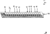
- FIG. 1 shows a drawer cabinet 1 as a preferred embodiment of a resource storage facility, as is largely customary for the storage of, in particular, resources and production resources, as well as tools in the field of production or crafts.
- a drawer cabinet system which is provided with a common control device 3 for the resource storage facility, here both drawer cabinets 1, of the resource storage facility system.
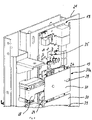
- the drawer cabinet 1 as shown in 2 has a body 4 made of sheet metal.
- Each of the drawers 5 of the drawer cabinet 1 is provided with drawer extension devices 6, for example with telescopically constructed so-called full extensions, as shown in 2 are partially shown.
- Individual drawers 5 can be pulled out of the body 4 and retracted back into the body 4 by means of these drawer pull-out devices 6, which are known per se.
- Each of the respective drawer pull-out devices 6 can be provided on each of the two sides of the respective drawer 5 with a guide track and with at least one guide element guided by the respective guide track, with the respective guide track on the body 4 or frame and the at least one guide element on the respective drawer 5 , or vice versa, are arranged.
- each guide track can be designed in particular as rollers.
- Guideways can be formed, for example, on rails, in particular telescopic rails 7 of the drawer pull-out devices 6, which are preferably attached to the body 4.
- Rollers or rollers for example, can be provided as guide bodies, which are preferably attached to the respective drawer 5 .
- the drawer cabinet 1 can be provided with an access authorization device 10 and with an individual pull-out safeguard 11 .
- the individual pull-out safeguard 11 With the individual pull-out safeguard 11, a simultaneous pull-out of more than one drawer 5—and thus also a risk of tipping due to too many pulled-out drawers 5—can be prevented.
- the access authorization device 10 can be used to determine, preferably in a variable manner, which drawers 5 are released for moving out of the body 4 and which drawers 5 are blocked for moving out. A drawer 5 that has not been released due to the access authorization device 10 can thus be blocked by this against being pulled out and remain blocked, although the individual pull-out protection 11 releases all drawers of the cabinet to be pulled out, since no drawer 5 is pulled out at the moment.
- both the access authorization device 10 and the individual pull-out safeguard 11 can use the same locking mechanism with which a drawer 5 and/or a group of drawers 5 of the drawer cabinet 1 are locked separately from other drawers 5 against being pulled out be able.
- a locking tongue 13 arranged in the area of the rear side of the respective drawer 5 can interact with a locking profile 12 arranged in the area of the rear wall of the body.
- a drawer 5 retracted into the body 4 engages in the locking profile 12 and depending on the position of the locking profile 12, this can positively grasp or grip behind or release the locking tongue 13, so that the locking tongue 13 and thus the drawer 5 belonging to the respective locking tongue 13 is locked against an excerpt.
- the present invention is not limited to the type of mechanical locking or release by a single pull-out safety device 11 described here.
- the individual pull-out safeguard 11 is preferably integrated into an electrical release device, which will be discussed below, or a component part of it, instead of the purely mechanical solution described above.
- the invention can be used with any individual pull-out protection and any access authorization device 10 .
- the drawer cabinet 1 can also be provided with a motorized locking device 14 .
- this has only one motor 15 which is operatively connected to the closure profile 11 by means of a driver rod.
- the motor 15 can be driven in both directions of rotation and thus the driver rod can be rotated in both directions of rotation.
- the locking profile 12 in one direction of rotation, can be transferred or brought into a first position (locked position), in which the drawers 5 in the cabinet are locked.
- the locking profile 12 is transferred to a second position in which the locking profile 12 is in a release position in which the locking profile 12 releases the drawers 5 for a drawer 5 to be pulled out.
- One direction of rotation of the motor 15 and thus also of the driver rod can thus be referred to as the closing direction and the other direction of rotation as the release direction.
- the locking profile 12 is pivoted or transferred back into the locking position without the action of a motor.
- the drawer 5 actuates the locking profile 12 accordingly when it is pulled out.
- This actuation can be carried out in particular by the locking tongue 13 of the drawer 5, which interacts with the locking profile 12 accordingly.
- the closure profile 11 is pivoted back or transferred back into its release position. This movement is also brought about by the closing tongue 13 of the retracting drawer 3 now being introduced into the locking profile 11 .
- closure profile 12 and the closure tongues are matched and adapted to one another so that the movements and processes described take place.
- Such a locking profile 12 and locking tongues 13 of the drawers engaging therein are disclosed, for example, by the applicant's drawer cabinets that were offered and sold many times before the filing date of this patent application, the disclosure content of which is hereby incorporated by reference.
- all the essentially rectangular prints 19, seen in the horizontal direction preferably have the same width.
- the height of each print 19 can be adapted to the height of the drawer 5 assigned to them or even be identical to it.
- the reference variable for the height of the drawer 5 can be the height of the rear wall 20 of the respective drawer 5 if the drawer height is not to be identical on all four sides of the respective drawer.
- the height of the prints 19 can preferably be kept in a specific grid dimension. For example in a 25mm pitch. Prints with a height of 50mm, 75mm, 100mm, 125mm, 150mm, 175mm, 200mm, 225mm, 250mm, 275mm and 300mm can be selected. In principle, however, any other regular or even irregular grid dimension can also be used in other embodiments of the invention. Even when using a grid dimension, the height of the respective print 19 should be adapted to the drawer height, which means that in such an embodiment of the invention the drawer heights should also be designed according to this grid dimension. Of course, in other embodiments of the invention, the print and thus also the drawer height can be selected independently of a grid dimension.
- the control device of the resource storage device can learn the height of the drawers provided in the cabinet by means of the carcass-side or the drawer-side prints 19, 32. Since each drawer is assigned only one carcase-side print, information about the respective drawer height can be stored in a component, for example a storage element, of the print, which information can be read out by the control device. Likewise, the controller can learn the position of the respective carcass-side prints, for example, in that each print is provided with a unique code and the controller can query the order of the codes. In this way, the controller can also find out the position of the respective drawer in the drawer cabinet and its height and take this into account when managing the stored goods and the drawers.
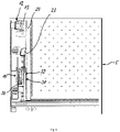
- embodiments of the invention can also be provided in which at least some, preferably all, of the prints 19 have the same height, although drawers 5 of different heights are provided. Such a possibility is in 7 shown. Only prints 19 of the same height are used here, the height of which is equal to or less than the height of the drawer 5 of the drawer cabinet 1, which has the smallest height. Since drawers 5 are also provided with a greater height in comparison thereto, gaps can arise in the column 18 between successive prints, ie the prints 19 are arranged at a distance from one another.
- the prints 19 can also be inserted into a grid strip 21, which is located on the rear wall of the drawer cabinet 1 and is provided with receiving recesses 22 for receiving.
- the grid recesses 22 are arranged one below the other in a constant grid dimension in at least one, preferably in several, vertical column(s).
- the respective body-side coil 30 can be arranged on a second body-side print 30a, which is located at a distance above the first print 30 and can have the same dimensions as the first print 19.
- the second body-side print 30a can be attached to the first print and electrically connected to it.
- the second body-side print 30a is located between the first body-side print 19 and the drawer-side coil 31 or drawer-side print 32.
- This solution of the second body-side coil can also be used in the exemplary embodiment of FIG 2 be provided.
- the top print 19 can be arranged on a holder attached to the rear wall of the body 4, for example the grid strip 21, and can be detachably fastened with separate fastening means, for example screwed onto it.
- the top print 19 in the column is hereby held securely on the body 4.
- the prints 19 that follow one another in column 18, including the second print from the top in column 18, can each be made by means of at least one Be plugged together 24 connecting means.
- Bus plugs 24, for example, can be considered as connecting means 24 between successive prints 19, as a result of which successive prints 19 are connected to one another and to the control device 3 with regard to a supply of electrical energy and for communication.
- the connecting means 24 can be located approximately in the middle, or at another point, on the respective horizontal edges of prints 19 directly following one another.
- the connecting means 24 thus connect the prints 19 to one another at least mechanically.
- the connecting means 24 have contact elements with which the connecting means 24 are each electrically conductively connected to the respective adjacent print 19 .
- the at least one connecting means 24 thus also connects the successive prints 19 to one another in an electrically conductive manner, so that electrical signals can be forwarded from one print 19 to the next print 19 in each case. Since preferably one of the prints 19, for example the uppermost print, is connected to the control device 3 with a bus cable, all other prints are also connected to the control by means of the connecting means 24 and can communicate with one another by exchanging data and signals.
- the connecting means 24 can be designed, for example, as bus plugs 24 or as bus cable sections 26 with attached bus plugs. So that the control device 3 can address and identify the individual drawers 5 in a targeted manner and separately from one another, it can also be provided that each drawer 5 is assigned a unique code that is only assigned to it. Both the control device 3 and the circuit logic of the print 19 of the respective drawer 5 recognize this unique code, which is only assigned to one of the drawers 5, and can therefore assign these signals accordingly.
- Each of the prints 19 can be provided with means to identify the position of the respective drawer 5 relative to the body 4, ie whether the drawer 5 is pulled out or pushed in.
- a proximity sensor 26 can be arranged on each of the prints 19, which detects the presence of the rear wall 20 of the respective drawer 5 in the immediate vicinity of the sensor 26 if the drawer 5 is pushed in. If, however, the respective drawer 5 is pulled out, the proximity sensor 26 does not generate a detection signal or one of the Absence of the respective drawer 5 corresponding signal. These signals are fed to the control device 3 via the bus line.
- the function of the proximity sensor can be taken over by a respective power coil 30 of the print 19 on the carcass side that is assigned to the respective drawer 5 .
- the body-side coil 30 serves the primary function of contactless transmission of electrical energy from the body-side to the drawer-side of the preferred resource storage facility.
- the ability of the body-side coil 30 to determine the proximity or distance of another coil by means of a measurable change in the resulting electrical conditions can preferably also be used, thereby realizing the function of a proximity sensor.
- the power coil 30 can detect the approach or removal of a drawer-side coil 31 or a sheet metal part of the drawer 5 due to its inductive properties, which is directly opposite the power coil when pushed in. By supplying corresponding detection signals from the coil 30 to the control device, this can detect the presence or absence of drawers in the area of the respective coil 30 and thus detect whether the respective drawer has been pushed in or out.
- Each of the prints 19 can also be provided with locking and unlocking means for their respective drawer. In the closed position, a drawer 5 can be blocked against being pulled out of the body with the locking and unlocking means. In the unlocked position, it can be released for moving out of the body.
- These locking and unlocking means can include a lifting magnet or electromagnet 28 or electric motor arranged on the respective print. Such a lifting magnet or electromagnet 28 can be arranged on top of or next to the respective print 19 . The respective lifting magnet or electromagnet 28 is electrically connected to the printed circuit assigned to it in order to be supplied with electrical energy and to carry out a lifting movement on the basis of signals from the control device for locking or unlocking.
- An electric motor 28 can also perform the same function as a lifting magnet, as is the case, for example, in 4 is shown.
- a linear movement when the lifting or electromagnet 28 is energized is used to move a locking element with which the respective drawer 5 can be either locked or unlocked by the movement.
- a plug can be provided on the print 19 for this purpose, into which the lifting magnet or electromagnet 28 is plugged.
- Commercial lifting or electromagnets or electric motors 28 can be used in connection with the invention. Such a lifting or electromagnet or electric motor 28 should preferably be provided on each of the prints 19 .
- lifting magnets or electric motors 28 can also be fastened in a manner other than with a plug-in connection.
- Components other than lifting magnets or electromagnets 28 can also be provided as locking and unlocking means.
- An alternative are, for example, electric lifting motors, which can be attached to the respective print in basically the same way as a lifting magnet.
- Each of the prints 19 can also belong to an energy supply device and preferably also to a communication device of each drawer 5 .
- each print 19 can be provided with at least one coil 30 .
- This at least one coil 30 of the body-side print 19 interacts with at least one coil 31 which is arranged on the drawer 5 assigned to this one print 19 in each case.
- the coil 31 on the drawer side is arranged on the back of the drawer 5, so that when the drawer 5 is completely pushed into the body 4, the two coils 30, 31 are parallel to one another and directly opposite one another with their coil axes, without mechanically interacting with one another to be in touch.
- the energy is transmitted without contact, for example by inductive coupling of these two coils, in which the body-side coil 30 is connected to an AC voltage power source, not shown in detail, and an AC voltage is induced in the drawer-side coil 31 by means of alternating current and an electromagnetic field.
- the current in the drawer-side circuit is transformed to direct current by means of rectification, which can preferably be arranged on a drawer-side print 32 like the coil 31, and can be stored in an accumulator also arranged on the respective drawer 5.
- each drawer 5 has its own accumulator 33, which is also advantageous to the respective Drawer 5 is attached.
- the battery 33 of each drawer 5 is thus charged primarily when it is in the pushed-in state.
- the electrical energy provided by the inductive coupling between the at least one body-side coil 30 and the at least one drawer-side coil 31 can also be used without intermediate storage by consumers of the corresponding drawer 5 .
- the rechargeable battery 33 provides an electrical supply for the electrical consumers arranged on or in the respective drawer 5 .
- the current originating from a power source, in particular the mains, and flowing through the body-side coil 30 can be controlled and monitored by a microprocessor 35 arranged on the body-side printed circuit board 19 in each case.
- the charging of the rechargeable battery 33 of a drawer 5 can also be controlled by a microprocessor.
- This further microprocessor 36 can be arranged on the drawer side and, for example, limit the level of the charging current and end the charging process as soon as the rechargeable battery 33 has reached its maximum charging capacity.
- the drawer-side microprocessor 36 assigned to one of the drawers can specify that the rechargeable battery of a drawer is only recharged in the event of a partial discharge when a certain minimum charging state is reached.
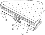
- a sensor 38 can be arranged on the body 4 or frame of the respective drawer cabinet 1, which detects the pull-out.
- the sensor 38 is located on the print 19 on the carcass side. It is particularly preferred here that in this context a component that is already present also assumes the function of such a pull-out sensor 38 .
- the coil 30 provided for the power supply and arranged on the print 19, in particular a print coil, can be used.
- the drawer-side coil 31 directly opposite the body-side coil 30 flows in the body-side coil 30 current, since this is now from the drawer-side coil 31 can be "consumed” due to the energy transfer.
- This power consumption is determined by the control device 3 and thus used as an indicator for the complete insertion of the drawer 5 in the body. If, on the other hand, the drawer 5 is fully or partially pulled out, there is no induction or a comparatively low induction in the coil 31 on the drawer side; this coil 31 therefore does not represent any electrical resistance for the coil 30 on the carcass side and no current therefore flows through the coil 30, what can thus also be used as an indicator for an extension of the drawer 5 from the body 4.
- An infrared transmitter/receiver unit 39 can be arranged on each print 19 in order to transmit signals by means of the communication device.
- Such an infrared transmitter/receiver unit 40 can also be located on the drawer 5, the two being configured to communicate with each other and in both directions, being able to exchange information and signals.
- the respective drawer-side infrared transmitter/receiver unit 40 can preferably be arranged on the drawer-side print 32 belonging to this respective drawer.
- each drawer 5 should preferably be configured in such a way that unrestricted communication with the drawers 5 works and can take place both when the drawer 5 is pushed in and when the drawer 5 is fully pulled out.
- infrared transmitter/receiver units 39, 40 this can also be possible, for example, with transmitter/receiver units that are based on radio technology, ie on signals that use modulated electromagnetic waves.
- Each drawer 5 is therefore preferably provided with its own transmitter/receiver unit 40 which exchanges data and signals with a transmitter/receiver unit 39 on the body. It is particularly preferred here for each drawer 5 to have its own transmitter/receiver unit 39 assigned to only this one drawer on the carcass side.
- the resource storage cupboards shown as preferred embodiments of a resource storage facility according to the invention can be part of a resource storage system that has several preferred embodiments of resource storage facilities according to the invention.
- the system idea can be that in addition to the drawer heights according to a specific grid dimension, the height of the prints 19, 32 are also designed according to this grid dimension, with several equipment storage cabinets being provided in different configurations of the print height and drawer height used. With different but predetermined cabinet heights, a largely free configuration with drawers 5 and associated prints 19, 32 from the available grid dimensions should preferably be possible.
Landscapes
- Engineering & Computer Science (AREA)
- Mechanical Engineering (AREA)
- Drawers Of Furniture (AREA)
Priority Applications (1)
| Application Number | Priority Date | Filing Date | Title |
|---|---|---|---|
| EP21000035.2A EP4035841A1 (fr) | 2021-02-02 | 2021-02-02 | Dispositif de stockage du moyen de production |
Applications Claiming Priority (1)
| Application Number | Priority Date | Filing Date | Title |
|---|---|---|---|
| EP21000035.2A EP4035841A1 (fr) | 2021-02-02 | 2021-02-02 | Dispositif de stockage du moyen de production |
Publications (1)
| Publication Number | Publication Date |
|---|---|
| EP4035841A1 true EP4035841A1 (fr) | 2022-08-03 |
Family
ID=74550404
Family Applications (1)
| Application Number | Title | Priority Date | Filing Date |
|---|---|---|---|
| EP21000035.2A Withdrawn EP4035841A1 (fr) | 2021-02-02 | 2021-02-02 | Dispositif de stockage du moyen de production |
Country Status (1)
| Country | Link |
|---|---|
| EP (1) | EP4035841A1 (fr) |
Cited By (1)
| Publication number | Priority date | Publication date | Assignee | Title |
|---|---|---|---|---|
| CN118323638A (zh) * | 2024-05-08 | 2024-07-12 | 无锡欣盛包装材料科技有限公司 | 一种纸板印刷用挂版自动抽拉存储装置 |
Citations (3)
| Publication number | Priority date | Publication date | Assignee | Title |
|---|---|---|---|---|
| JP2017005937A (ja) * | 2015-06-15 | 2017-01-05 | 株式会社日立システムズ | サーバラックシステム、サーバラック装置、及びit機器 |
| EP3168012A2 (fr) * | 2015-11-02 | 2017-05-17 | TRL Enterprises LLC | Système de gestion d'outils |
| DE102018206879A1 (de) * | 2018-05-04 | 2019-11-07 | Robert Bosch Gmbh | Werkzeugaufbewahrungsvorrichtung |
-
2021
- 2021-02-02 EP EP21000035.2A patent/EP4035841A1/fr not_active Withdrawn
Patent Citations (3)
| Publication number | Priority date | Publication date | Assignee | Title |
|---|---|---|---|---|
| JP2017005937A (ja) * | 2015-06-15 | 2017-01-05 | 株式会社日立システムズ | サーバラックシステム、サーバラック装置、及びit機器 |
| EP3168012A2 (fr) * | 2015-11-02 | 2017-05-17 | TRL Enterprises LLC | Système de gestion d'outils |
| DE102018206879A1 (de) * | 2018-05-04 | 2019-11-07 | Robert Bosch Gmbh | Werkzeugaufbewahrungsvorrichtung |
Cited By (1)
| Publication number | Priority date | Publication date | Assignee | Title |
|---|---|---|---|---|
| CN118323638A (zh) * | 2024-05-08 | 2024-07-12 | 无锡欣盛包装材料科技有限公司 | 一种纸板印刷用挂版自动抽拉存储装置 |
Similar Documents
| Publication | Publication Date | Title |
|---|---|---|
| EP3505466B1 (fr) | Système de rayonnage automatisé et son procédé de fonctionnement sécurisé | |
| DE69926707T2 (de) | Steuervorrichtung für die Öffnung einer Tür | |
| EP0070028B1 (fr) | Sécurité pour chariots de supermarchés, chariots porte-bagages ou analogues | |
| EP1749341B2 (fr) | Systeme de stockage a rayonnages a reinjection d'energie | |
| WO2000053871A1 (fr) | Systeme de fermeture d'armoire | |
| DE102013111570A1 (de) | Arbeitszellenanordnung und Roboterzellenanordnung mit einer solchen | |
| EP2736062A1 (fr) | Système de commande modulaire | |
| EP3452966B1 (fr) | Procédé de logistique de stockage | |
| AT10100U1 (de) | Möbel mit wenigstens einem gegenüber einem ersten möbelteil motorisch bewegbaren zweiten möbelteil | |
| DE102004049024B3 (de) | Positionsüberwachungseinrichtung | |
| DE102004031581B4 (de) | Spurgeführtes Transportsystem | |
| WO2017167473A1 (fr) | Ensemble bobine primaire | |
| DE102019131365A1 (de) | Lager mit mindestens einer Regaleinrichtung | |
| EP4004318A1 (fr) | Système de sécurité de porte, procédé de fonctionnement d'un système de sécurité de porte et moyen de transport | |
| DE102016121749A1 (de) | Übernahmewagen | |
| EP4035841A1 (fr) | Dispositif de stockage du moyen de production | |
| EP3471235A2 (fr) | Dispositif de fourniture d'énergie destiné à fournir de l'énergie électrique à un véhicule automobile ainsi que procédé de fonctionnement d'un dispositif de fourniture d'énergie | |
| DE102019100251A1 (de) | Transportable Ladestation | |
| EP4035840B1 (fr) | Dispositif de stockage du moyen de production doté d'un dispositif de transfert d'énergie pour au moins un tiroir | |
| DE19729722A1 (de) | Mietfachanlage | |
| DE102022128505A1 (de) | System mit Lastübergabestation und Transportfahrzeug | |
| DE202018100945U1 (de) | Werkstattwagen mit Display an Griffseite | |
| DE202011003345U1 (de) | Energiespeichereinheit, Energiespeichereinheitengehäuse und Wechselstation für Energiespeichereinheiten | |
| EP2562844A1 (fr) | Appareil de commande | |
| DE102017102251A1 (de) | Ladesäule |
Legal Events
| Date | Code | Title | Description |
|---|---|---|---|
| PUAI | Public reference made under article 153(3) epc to a published international application that has entered the european phase |
Free format text: ORIGINAL CODE: 0009012 |
|
| STAA | Information on the status of an ep patent application or granted ep patent |
Free format text: STATUS: THE APPLICATION HAS BEEN PUBLISHED |
|
| AK | Designated contracting states |
Kind code of ref document: A1 Designated state(s): AL AT BE BG CH CY CZ DE DK EE ES FI FR GB GR HR HU IE IS IT LI LT LU LV MC MK MT NL NO PL PT RO RS SE SI SK SM TR |
|
| STAA | Information on the status of an ep patent application or granted ep patent |
Free format text: STATUS: REQUEST FOR EXAMINATION WAS MADE |
|
| 17P | Request for examination filed |
Effective date: 20230203 |
|
| RBV | Designated contracting states (corrected) |
Designated state(s): AL AT BE BG CH CY CZ DE DK EE ES FI FR GB GR HR HU IE IS IT LI LT LU LV MC MK MT NL NO PL PT RO RS SE SI SK SM TR |
|
| TPAC | Observations filed by third parties |
Free format text: ORIGINAL CODE: EPIDOSNTIPA |
|
| STAA | Information on the status of an ep patent application or granted ep patent |
Free format text: STATUS: THE APPLICATION IS DEEMED TO BE WITHDRAWN |
|
| 18D | Application deemed to be withdrawn |
Effective date: 20250902 |