EP4035982A1 - Guidon de bicyclette ayant des caractéristiques de performance directionnelles - Google Patents
Guidon de bicyclette ayant des caractéristiques de performance directionnelles Download PDFInfo
- Publication number
- EP4035982A1 EP4035982A1 EP22153713.7A EP22153713A EP4035982A1 EP 4035982 A1 EP4035982 A1 EP 4035982A1 EP 22153713 A EP22153713 A EP 22153713A EP 4035982 A1 EP4035982 A1 EP 4035982A1
- Authority
- EP
- European Patent Office
- Prior art keywords
- handlebar
- ellipses
- cross
- control end
- section
- Prior art date
- Legal status (The legal status is an assumption and is not a legal conclusion. Google has not performed a legal analysis and makes no representation as to the accuracy of the status listed.)
- Granted
Links
Images




Classifications
-
- B—PERFORMING OPERATIONS; TRANSPORTING
- B62—LAND VEHICLES FOR TRAVELLING OTHERWISE THAN ON RAILS
- B62K—CYCLES; CYCLE FRAMES; CYCLE STEERING DEVICES; RIDER-OPERATED TERMINAL CONTROLS SPECIALLY ADAPTED FOR CYCLES; CYCLE AXLE SUSPENSIONS; CYCLE SIDECARS, FORECARS, OR THE LIKE
- B62K21/00—Steering devices
- B62K21/12—Handlebars; Handlebar stems
-
- B—PERFORMING OPERATIONS; TRANSPORTING
- B64—AIRCRAFT; AVIATION; COSMONAUTICS
- B64C—AEROPLANES; HELICOPTERS
- B64C13/00—Control systems or transmitting systems for actuating flying-control surfaces, lift-increasing flaps, air brakes, or spoilers
- B64C13/02—Initiating means
- B64C13/04—Initiating means actuated personally
- B64C13/042—Initiating means actuated personally operated by hand
Definitions
- Embodiments of the invention generally relate to steering components such as handlebars.
- a handlebar is used for steering a vehicle. Normally, the movement of the handlebar results in a change to the direction of travel for the vehicle. On a ground (or water) vehicle, the movement of the handlebar will usually result in a turn to the left or the right. In an air vehicle, the movement of the handlebar can result in a change to one or more of a roll, a pitch, and possibly even a yaw.
- a handlebar comprising a stem clamp region.
- the handlebar may comprise a plurality of control end regions.
- the handlebar may comprise a plurality of transition regions.
- a cross-section of at least a portion of one or more of said plurality of transition regions may comprise an asymmetric cross-section based on an intersection of a plurality of ellipses and defined by four different radii R1, R2, R3, R4 and an angle ( ⁇ ) of an axis of symmetry of said ellipses.
- the plurality of ellipses may have coincident centers.
- the axis of symmetry of said ellipses may be a major axis of symmetry for each of said plurality of ellipses.
- the axis of symmetry of said ellipses may be a major axis of symmetry for at least two of said plurality of ellipses.
- none of said four different radii are equal.
- the angle ( ⁇ ) of said axis of symmetry of said ellipses may vary along a length of at least one of said plurality of transition regions.
- said four different radii R1, R2, R3, R4 may vary along a length of at least one of said plurality of transition regions.
- a cross-section of at least one of said plurality of control end regions may be substantially symmetric.
- a cross-section of said stem clamp region may be substantially symmetric.
- a cross-section of at least a portion of said stem clamp region may comprise an asymmetric cross-section based on said intersection of said plurality of ellipses and defined by said four different radii R1, R2, R3, R4 and said angle ( ⁇ ) of said axis of symmetry of said plurality of ellipses.
- the plurality of ellipses may have coincident centers.
- a cross-section of at least a portion of one or more of said plurality of control end regions may comprises an asymmetric cross-section based on said intersection of said plurality of ellipses and defined by said four different radii R1, R2, R3, R4 and said angle ( ⁇ ) of said axis of symmetry of said plurality of ellipses.
- the plurality of ellipses may have coincident centers.
- said plurality of transition regions may comprise two transition regions, and each of said two transition regions is located between said stem clamp region and said plurality of said control end regions.
- a handlebar comprising a stem clamp region.
- the handlebar may comprise a plurality of control end regions.
- the handlebar may comprise a plurality of transition regions.
- a cross-section of at least a portion of said stem clamp region may comprise an asymmetric cross-section based on an intersection of four ellipses and defined by four different radii R1, R2, R3, R4 and an angle ( ⁇ ) of an axis of symmetry of said ellipses.
- the four ellipses may have coincident centers.
- the axis of symmetry of said ellipses may be a major axis of symmetry for all four ellipses.
- the axis of symmetry of said ellipses may be a major axis of symmetry for at least two of said four ellipses.
- none of said four different radii are equal.
- said angle ( ⁇ ) of said axis of symmetry of said ellipses varies along a length of said stem clamp region.
- said four different radii R1, R2, R3, and R4 may vary along a length said stem clamp region.
- At least a portion of one or more of said plurality of control end regions and at least a portion of one or more of said plurality of said transition regions may be substantially symmetric.
- a cross-section of at least a portion of one or more of said plurality of transition regions may comprise an asymmetric cross-section based on said intersection of said four ellipses and defined by said four different radii R1, R2, R3, R4 and said angle ( ⁇ ) of said axis of symmetry of said four ellipses.
- the four ellipses may have coincident centers.
- a cross-section of at least a portion of one or more of said plurality of control end regions may comprise an asymmetric cross-section based on said intersection of said four ellipses and defined by said four different radii R1, R2, R3, R4 and said angle ( ⁇ ) of said axis of symmetry of said four ellipses.
- the four ellipses may have coincident centers.
- a handlebar comprising a stem clamp region.
- the handlebar may comprise a plurality of control end regions.
- the handlebar may comprise a plurality of transition regions.
- a cross-section of at least a portion of one or more of said plurality of control end regions may comprise an asymmetric cross-section based on an intersection of four ellipses and defined by four different radii R1, R2, R3, R4 and an angle ( ⁇ ) of an axis of symmetry of said ellipses.
- the four ellipses may have coincident centers.
- said axis of symmetry of said ellipses may be a major axis of symmetry for each of said four ellipses.
- said axis of symmetry of said ellipses may be a major axis of symmetry for two ellipses.
- none of said four different radii are equal.
- said angle ( ⁇ ) of said axis of symmetry of said ellipses may vary along a length of at least one of said plurality of said control end regions.
- said four different radii R1, R2, R3, R4 may vary along a length of at least one of said plurality of control end regions.
- said stem clamp region and at least a portion of one or more of said plurality of said transition regions may be substantially symmetric.
- a cross-section of at least a portion of one or more of said plurality of transition regions may comprise an asymmetric cross-section based on said intersection of said four ellipses and defined by said four different radii R1, R2, R3, R4 and said angle ( ⁇ ) of said axis of symmetry of said four ellipses.
- the four ellipses may have coincident centers.
- a cross-section of at least a portion of said stem clamp region may comprise an asymmetric cross-section based on said intersection of said four ellipses and defined by said four different radii R1, R2, R3, R4 and said angle ( ⁇ ) of said axis of symmetry of said four ellipses.
- the four ellipses may have coincident centers.
- a handlebar comprising a stem clamp region.
- the handlebar may comprise control end regions.
- the handlebar may comprise transition regions.
- a cross-section of each of the transition regions may be formed by the intersection of four ellipses and defined by four radii R1, R2, R3, R4 and an angle ( ⁇ ) of an axis of symmetry of the ellipses.
- the four ellipses may have coincident centers.
- the axis of symmetry of the ellipses may be a major axis of symmetry for all four ellipses.
- the axis of symmetry of the ellipses may be a major axis of symmetry for two ellipses.
- each of the four radii may not be equal.
- the angle ( ⁇ ) of the axis of symmetry of the ellipses may vary along the length of the transition region.
- R1, R2, R3, and R4 may vary along the length of each transition region.
- each control end region may be substantially circular.
- a cross-section of the stem clamp region may be substantially circular.
- a cross-section of the stem clamp region may be formed by the intersection of four ellipses and defined by four radii R1, R2, R3, R4 and an angle ( ⁇ ) of the axis of symmetry of the four ellipses.
- the four ellipses may have coincident centers.
- a cross-section of each control end region may be formed by the intersection of four ellipses and defined by four radii R1, R2, R3, R4 and an angle ( ⁇ ) of the axis of symmetry of the four ellipses.
- the four ellipses may have coincident centers.
- the transition regions may comprise two transition regions, and each of the two transition regions is located between the stem clamp region and the control end region.
- a handlebar comprising a stem clamp region.
- the handlebar may comprise control end regions.
- the handlebar may comprise transition regions.
- a cross-section of the stem clamp region may be formed by the intersection of four ellipses and defined by four radii R1, R2, R3, R4 and an angle ( ⁇ ) of an axis of symmetry of the ellipses.
- the four ellipses may have coincident centers.
- the axis of symmetry of the ellipses may be a major axis of symmetry for all four ellipses.
- the axis of symmetry of the ellipses may be a major axis of symmetry for two ellipses.
- each of the four radii may be not equal.
- the angle ( ⁇ ) of the axis of symmetry of the ellipses may vary along the length of the stem clamp region.
- R1, R2, R3, and R4 may vary along the length the stem clamp region.
- a cross-section of the transition regions may be formed by the intersection of four ellipses and defined by four radii R1, R2, R3, R4 and an angle ( ⁇ ) of the axis of symmetry of the four ellipses.
- the four ellipses may have coincident centers.
- a cross-section of each control end region may be formed by the intersection of four ellipses and defined by four radii R1, R2, R3, R4 and an angle ( ⁇ ) of the axis of symmetry of the four ellipses.
- the four ellipses may have coincident centers.
- a handlebar comprising a stem clamp region.
- the handlebar may comprise control end regions.
- the handlebar may comprise transition regions.
- a cross-section of the control end regions is formed by the intersection of four ellipses and defined by four radii R1, R2, R3, R4 and an angle ( ⁇ ) of an axis of symmetry of the ellipses.
- the four ellipses may have coincident centers.
- the axis of symmetry of the ellipses may be a major axis of symmetry for all four ellipses.
- the axis of symmetry of the ellipses may be a major axis of symmetry for two ellipses.
- each of the four radii may not be equal.
- the angle ( ⁇ ) of the axis of symmetry of the ellipses may vary along the length of each of the control end region.
- R1, R2, R3, and R4 may vary along the length of each of the control end region.
- a cross-section of the transition regions may be formed by the intersection of four ellipses and defined by four radii R1, R2, R3, R4 and an angle ( ⁇ ) of the axis of symmetry of the four ellipses.
- the four ellipses may have coincident centers.
- a cross-section of the stem clamp region may be formed by the intersection of four ellipses and defined by four radii R1, R2, R3, R4 and an angle ( ⁇ ) of the axis of symmetry of the four ellipses.
- the four ellipses may have coincident centers.
- a vehicle comprising a handlebar as set out in any of the various embodiments above and/or having any of the features described anywhere herein.
- the vehicle may be in the form of a bicycle, an electric bike (e-bike), a moped, a motorcycle, a snow machine, a personal watercraft (PWC), or aircraft.
- e-bike electric bike
- PWC personal watercraft
- the dynamic response (resonant frequency and damping ratio) and structural properties (stiffness and strength) for optimal user experience are not isotropic, but are instead specific to different planes of the handlebar (fore-aft plane and vertical plane, etc.).
- Embodiments disclosed herein adjust the asymmetry of at least a portion of a handlebar (as identified by an asymmetric cross-section) in response to various frequencies imparted to the handlebar while maintaining appropriate structural properties for the handlebar.
- the asymmetric cross-section(s) of the handlebar are configured to reduce and/or change vibrational and/or resonant frequencies that would otherwise be transferred from the handlebar to a user during travel
- the asymmetric cross-section(s) of the handlebar are configured to modify the aerodynamic profile of the handlebar to reduce air resistance during high-speed travel.
- a circular cross-section of a stem clamp region of the handlebar can negatively affect the aerodynamic characteristics of the handlebar.
- handlebars with circular cross-section stem clamp regions tend to rotate in a stem clamp, which may cause a crash.
- the asymmetric cross-section(s) of the handlebar stem clamp region are configured to reduce and/or prevent the rotation of the handlebar in the stem clamp thereby improving the user's safety and comfort.
- the asymmetric cross-section(s) of the handlebar are configured for one or both control end regions of the handlebar, which allows for a positioning of bicycle controls (brakes, grips, gear shifters, etc.) in a way that improves the user's comfort and prevents user fatigue.
- a circular cross-section at a control end region can allow the vehicle controls mounted thereto to rotate on the handlebar contributing to the rider's fatigue and causing potential danger of a crash.
- the rotation of the bicycle controls on the handlebar can be reduced and/or completely eliminated.
- the one or more uniquely defined asymmetric cross-sections in one or more different regions of the handlebar are configured to create different dynamic response and structural properties in multiple planes (e.g., a fore-aft plane, a vertical (or side-to-side) plane, both the fore-aft and vertical plane, etc.).
- the one or more uniquely defined asymmetric cross-sections in one or more different regions of the handlebar are not symmetric oval shapes as they would not meet the desired geometric constraints of the handlebar, e.g., the required upsweep and/or backsweep, smooth transitions between sections of the handlebar, and the like.
- the one or more uniquely defined asymmetric cross-sections in one or more different regions of the handlebar are configured to provide improvements to normal handlebar aerodynamic characteristics as well as user safety and comfort.
- a bicycle is utilized as the example vehicle.
- the handlebar could be used on one or more of a variety of vehicles such as, but not limited to, a bicycle, an electric bike (e-bike), a moped, a motorcycle, a snow machine, a personal watercraft (PWC), aircraft, or any vehicle that utilizes a bar style steering assembly, e.g., a stick in an aircraft, a U or W shaped aircraft steering assembly, etc.
- bicycle 50 has a frame 24 with a suspension system comprising a swing arm 26 that, in use, is able to move relative to the rest of frame 24; this movement is permitted by, inter alia, rear shock assembly 38.
- the front fork assembly 34 also provide a suspension function via a shock assembly in at least one fork leg.
- bicycle 50 is a full suspension bicycle. In another embodiment, bicycle 50 has only a front suspension and no rear suspension (e.g., a hard tail). In different embodiments, bicycle 50 could be a road bike, a mountain bike, a gravel bike, an electric bike (e-bike), a hybrid bike, a motorcycle, or the like.
- swing arm 26 is pivotally attached to the frame 24 at pivot point 12 which is located above the bottom bracket axis 11.
- pivot point 12 is shown in a specific location, it should be appreciated that pivot point 12 can be found at different distances from bottom bracket axis 11 depending upon the rear suspension configuration. The use of the specific pivot point 12 herein is provided merely for purposes of clarity.
- Bottom bracket axis 11 is the center of the pedal and crank assembly 13.
- pivot point 12 is shown in a specific location, it should be appreciated that pivot point 12 can be found at a different location depending upon the rear suspension configuration. The use of the pivot point 12 herein is provided merely for purposes of clarity.
- frame 24 and swing arm 26 would be formed as a fixed frame.
- Bicycle 50 includes a front wheel 28 which is coupled with the front fork assembly 34 via axle 85.
- front fork assembly 34 includes a crown 31.
- a portion of front fork assembly 34 e.g., a steerer tube
- bicycle 50 includes a rear wheel 30 which is coupled to the swing arm 26 at rear axle 15.
- a rear shock assembly 38 is positioned between the swing arm 26 and the frame 22 to provide resistance to the pivoting motion of the swing arm 26 about pivot point 12.
- the illustrated bicycle 50 includes a suspension member between swing arm 26 and the frame 24 which operate to substantially reduce rear wheel 30 impact forces from being transmitted to the rider of the bicycle 50.
- bicycle 50 is driven by a chain 19 that is coupled with both crank assembly 13 and rear sprocket 18.
- the rotational input to crank arms 100 cause the crank assembly 13 to rotate about bottom bracket axis 11.
- This rotation applies a force to chain 19 which transfers the rider generated rotational energy to rear sprocket 18 which results in the rotation of rear wheel 30.
- Chain tension device 17 provides a variable amount of tension on chain 19.
- the need for chain 19 length variation can be due to a number of different gears that may be on one or both of crank assembly 13 and/or rear sprocket 18 and/or changes in chain stay length as the distance between bottom bracket axis 11 (where crank assembly 13 attaches to frame 24) and the rear axle 15 changes due to suspension articulation.
- saddle 32 is connected to the frame 24 via seatpost 33.
- seatpost 33 is a dropper seatpost.
- bicycle 50 may include one or more active suspension components, sensors, and the like, such as disclosed in U.S. Patent 10,036,443 which is incorporated by reference herein, in its entirety.
- handlebar 36 is broken down into a number of subsections, e.g., 101-105.
- handlebar 36 consists of stem clamp region 103, two transition regions (e.g., transition region 102 and transition region 104), and two control end regions (e.g., control end region 101 and control end region 105).
- handlebar 36 is attached to bicycle 50 via a handlebar stem clamped at stem clamp region 103.
- controls and components such as, but not limited to, brake levers, grips, throttle, gear shifter, and the like are coupled to the handlebar 36 at one or both of control end regions (e.g., control end region 101 and control end region 105).
- control end regions e.g., control end region 101 and control end region 105
- the layout of the controls and components at one or both of control end regions is defined by the manufacturer.
- the layout of one or more of the controls and components at one or both of control end regions is arranged by the user.
- handlebar 36 comprise a material such as an aluminum alloy, a titanium alloy, steel, other metal alloys, metals, ceramic, or the like.
- some of the components of handlebar 36 comprise a composite material such a composite material with a thermoset or thermoplastic matrix, a long or short fiber thermoplastic or thermoset composite, injection molded carbon fiber, carbon fiber reinforced nylon, carbon fiber reinforced epoxy resin, glass filled nylon, a compression molded material, composite layering, chopped carbon fibers, plastic, a polymer, long fiber-reinforced plastics, short-fiber reinforced plastics, or the like.
- one, some, or all of the components of handlebar 36 could be formed from a combination of these materials, e.g., a composite/metal hybrid.
- the handlebar assembly can be manufactured by a variety of methods such as compression molding, bladder molding, vacuum molding, resin transfer molding (RTM), filament winding, automated fiber placement (AFP), automated tape laying (ATL), or the like.
- the cross-section of at least a portion of the stem clamp region 103 is asymmetric while the cross-section of one or both of the control end regions (e.g., control end region 101 and/or control end region 105) and one or both of the transition regions (e.g., transition region 102 and/or transition region 104) are symmetric.
- the cross-section of at least a portion of one or both of the control end regions is asymmetric while the cross-section of both the stem clamp region 103 and one or both of the transition regions (e.g., transition region 102 and/or transition region 104) are symmetric.
- the cross-section of at least a portion of one or both of the transition regions is asymmetric while the cross-section of both the stem clamp region 103 and one or both of the control end regions (e.g., control end region 101 and/or control end region 105) are symmetric.
- the cross-section of at least a portion of one or both of the control end regions (e.g., control end region 101 and/or control end region 105) and one or both of the transition regions (e.g., transition region 102 and/or transition region 104) are asymmetric while the cross-section of the stem clamp region 103 is symmetric.
- the cross-section of at least a portion of the stem clamp region 103 and at least a portion of one or both of the control end regions are asymmetric while the cross-section of one or both of the transition regions (e.g., transition region 102 and/or transition region 104) are symmetric.
- the cross-section of at least a portion of the stem clamp region 103 and at least a portion of one or both of the transition regions are asymmetric while the cross-section of one or both of the control end regions (e.g., control end region 101 and/or control end region 105) are symmetric.
- the cross-section of at least a portion of the stem clamp region 103, at least a portion of one or both of the control end regions (e.g., control end region 101 and/or control end region 105), and at least a portion of one or both of the transition regions (e.g., transition region 102 and/or transition region 104) are asymmetric.
- the cross-section of at least a portion of the stem clamp region 103, at least a portion of both control end regions (e.g., control end region 101 and control end region 105), and at least a portion of both of the transition regions (e.g., transition region 102 and transition region 104) are asymmetric.
- embodiments of the handlebar 36 comprising at least a portion of asymmetric cross-section(s) are able to reduce and/or change the vibrations or other unwanted effects imparted to a vehicle user based on the conditions that the vehicle and/or handlebar 36 is experiencing.
- handlebar 36 comprising at least a portion of asymmetric cross-section(s) "translates" the vibration that will be transferred to the user. That is, by adjusting the non-uniformity of the asymmetric cross-section(s), handlebar 36 alters the frequencies (makes the frequencies higher or lower) that are ultimately passed to the vehicle user. It should be further noted that in various embodiments, where it is desired to reduce the amplitude of a particular frequency, handlebar 36 reduces the vibration that will be transferred to the user by adjusting the non-uniformity of the asymmetric cross-section(s). Conversely, it should be further noted that in various embodiments, where it is desired to increase the amplitude of a particular frequency, handlebar 36 amplifies the vibration by adjusting the non-uniformity of the asymmetric cross-section(s).
- embodiments of the handlebar 36 explicitly describe adjusting the non-uniformity of the asymmetric cross-section(s), various other embodiments of the present invention adjust the response and operation of the handlebar 36 by varying the material comprising at least a portion of the handlebar 36. It should further be noted that the present invention also includes embodiments is which the non-uniformity of the asymmetric cross-section(s) are adjusted, and the material comprising at least a portion of the handlebar 36 is varied.
- FIG. 3 a front view of a portion of the handlebar 36 of Figure 2 with a number of cross-sections (e.g., cross-sections A-A through Q-Q) annotated thereon is shown in accordance with an embodiment.
- cross-sections A-A through Q-Q are not an axis-symmetric surface of revolution along the entire axial span of handlebar 36. That is, in various embodiments, cross-sections A-A through Q-Q of handlebar 36 are non-uniform at, at least, one location along the axial span of handlebar 36. Moreover, in embodiments of the present invention, the asymmetric cross-section(s) such as cross-sections A-A through Q-Q may be at any given location along the axial span of handlebar 36.
- the asymmetric cross-section(s) will be non-uniform along half the axial span of handlebar 36 beginning at approximately the middle of stem clamp region 103 and will be mirrored to the other half of the axial span of handlebar 36. Additionally, in one embodiment, the asymmetric cross-section(s) will be non-uniform along the entire axial span of handlebar 36.
- handlebar 36 will have a non-uniform asymmetric cross-section lengths at multiple locations along the axial span of handlebar 36. Furthermore, it should be noted, that in one embodiment, handlebar 36 may have a uniform asymmetric cross-section length at, at least, one location along the axial span of handlebar 36.
- stem clamp region 103 includes cross-sections A-A and B-B.
- the transition region e.g., transition region 102 and/or transition region 1014
- the end region e.g., control end region 101 and/or control end region 105) includes cross-sections O-O through Q-Q.
- asymmetric cross-section(s) of handlebar 36 are oval in shape.
- asymmetric cross-section(s) of handlebar 36 may be selected from shapes such as, but not limited to, egg-shaped, elliptically-shaped, rectangularly-shaped, other geometric shapes, and/or a combination of two or more different shapes.
- asymmetric cross-section(s) of handlebar 36 are different thickness.
- handlebar 36 has at least one asymmetric cross-section(s) at, at least, one location along the axial span of handlebar 36.
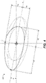
- perspective view 400 of the different radial measurements and angles for one or more of the cross-sections of Figure 3 in a first plane is shown in accordance with an embodiment.
- perspective view 400 provides an example of a cross-section region of handlebar 36 formed by the intersection of 4 ellipses and defined by 4 radii (R1, R2, R3, R4) and interior of angle ( ⁇ ) of axis 6 of symmetry of the ellipses.
- 4 ellipses are shown in Figure 4 , it should be appreciated that more or fewer ellipses may be used to generate each cross-section.
- the use of 4 ellipses is provided as one embodiment used to generate the desired shape for one or more of the given cross-sections.
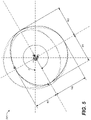
- perspective view 500 of the different radial measurements and angles for one or more of the cross-sections of Figure 3 in a second plane is shown in accordance with an embodiment.
- perspective view 500 provides an example of a cross-section region of handlebar 36 formed by the intersection of 4 ellipses and defined by 4 radii (R1, R2, R3, R4) and exterior of angle ( ⁇ ) of axis of symmetry of the ellipses that is about a different axis than axis 6.
- 4 ellipses are shown in Figure 5 , it should be appreciated that more or fewer ellipses may be used to generate each cross-section.
- the use of 4 ellipses is provided herein as one embodiment used to generate the desired shape for one or more of the given cross-sections.
- stem clamp region 103 includes cross-sections A-A and B-B. In one embodiment, cross-sections A-A and B-B are both asymmetric. In one embodiment, cross-sections A-A is asymmetric and cross-section B-B is symmetric. In one embodiment, cross-sections A-A is symmetric and cross-section B-B is asymmetric. In another embodiment, the stem clamp region 103 may include other cross-sections such as cross-sections C-C through Q-Q.
- cross-sections A-A and B-B are formed by the intersection of 4 ellipses and defined by 4 radii (R1, R2, R3, R4) and angle ( ⁇ ) of axis (6) of symmetry of the ellipses.
- the shape of stem clamp region 103 provides a smooth transition (eliminating stress concentration in the handlebar 36) between stem clamp region 103 and transition regions (e.g., transition region 102 and transition region 104).
- the shape of a cross-section of at least a portion of stem clamp region 103 is asymmetrically designed to improve the aerodynamic characteristics of the stem clamp region 103 of handlebar 36.
- the shape of a cross-section of at least a portion of stem clamp region 103 is asymmetrically designed to reduce handlebar vibrations transferred to the user.
- the shape of a cross-section of at least a portion of stem clamp region 103 is asymmetrically designed to reduce and/or prevent the rotation of the handlebar 36 within the stem clamp. In one embodiment, by reducing handlebar 36 vibration and/or preventing the rotation of handlebar 36 in the stem clamp, a user's safety and comfort is improved while steering feedback is maintained along with vehicle controllability.
- stem clamp region 103 uses R1 ⁇ R2 ⁇ R3 ⁇ R4 (e.g., asymmetric cross-section shape) with R1, R2, R3, R4 varying along the length of the region.
- R1, R2, R3, R4 varying along the length of the region.
- the angle ( ⁇ ) of the axis (6) of symmetry of the ellipses can vary along the length of the stem clamp region 103.
- the dynamic response and structural properties of the handlebar 36 can be adjusted in multiple planes.
- control end regions e.g., control end region 101 and control end region 105) and/or transition regions (e.g., transition region 102 and transition region 104) have R1 ⁇ R2 ⁇ R3 ⁇ R4 (e.g., asymmetric cross-section shape).
- FIG. 7 a plurality of cross-section views including cross-sections J-J through Q-Q of Figure 3 are shown in accordance with an embodiment.
- transition regions include one or more of cross-sections C-C through N-N.
- the transition regions may include other cross-sections such as cross-sections A-A through B-B and O-O through Q-Q.
- cross-sections C-C through N-N are formed by the intersection of 4 ellipses and defined by 4 radii (R1, R2, R3, R4) and angle ( ⁇ ) of axis (6) of symmetry of the ellipses.
- the asymmetric shape of the cross-sections of the transition regions use R1 ⁇ R2 ⁇ R3 ⁇ R4 (e.g., asymmetric cross-section shape) with R1, R2, R3, R4 varying along the length of the region to achieve a smooth transition (to eliminate stress concentration in the handlebar 36) between control end regions (e.g., control end region 101 and/or control end region 105) and stem clamp region 103.
- the variations in cross-sections are designed to reduce handlebar vibrations transferred to the user thereby improving the user's comfort while retaining (or even enhancing) steering feedback and vehicle controllability.
- the angle ( ⁇ ) of the axis (6) of symmetry of the ellipses can vary along the length of the transition regions (e.g., transition region 102 and transition region 104). In one embodiment, as R1, R2, R3, R4 and ⁇ are varied along the length of the transition regions (e.g., transition region 102 and transition region 104) the dynamic response and structural properties of the handlebar can be adjusted in multiple planes.
- control end regions e.g., control end region 101 and control end region 105) and/or stem clamp region 103 have R1 ⁇ R2 ⁇ R3 ⁇ R4 (e.g., asymmetric cross-section shape).
- control end regions include one or more of cross-sections O-O through Q-Q.
- control end regions e.g., control end region 101 and control end region 105
- cross-sections O-O through Q-Q are formed by the intersection of 4 ellipses and defined by 4 radii (R1, R2, R3, R4) and angle ( ⁇ ) of axis (6) of symmetry of the ellipses.
- the asymmetric shape of the cross-sections of the control end regions use R1 ⁇ R2 ⁇ R3 ⁇ R4 (e.g., asymmetric cross-section shape) with R1, R2, R3, R4 varying along the length of the region to achieve a smooth transition (to eliminate stress concentration in the handlebar 36) between transition regions (e.g., transition region 102 and/or transition region 104) and control end regions (e.g., control end region 101 and/or control end region 105).
- control end regions e.g., control end region 101 and/or control end region 105
- control end regions e.g., control end region 101 and/or control end region 105
- control end regions are designed to reduce handlebar vibrations transferred to the user thereby improving the user's comfort while retaining (or even enhancing) steering feedback and vehicle controllability.
- control end regions e.g., control end region 101 and/or control end region 105
- variations in the asymmetric cross-sections across control end regions are designed to prevent the rotation of one or more controls and components such as, but not limited to, brake levers, grips, throttle, gear shifter, and the like, attached to the control end regions (e.g., control end region 101 and/or control end region 105) thereby improving the user's safety.
- the angle ( ⁇ ) of the axis (6) of symmetry of the ellipses can vary along the length of the control end regions (e.g., control end region 101 and/or control end region 105). In one embodiment, as R1, R2, R3, R4 and ⁇ are varied along the length of the control end regions (e.g., control end region 101 and/or control end region 105) such that the dynamic response and structural properties of the handlebar 36 can be adjusted in multiple planes.
- the asymmetric cross-section(s) are selected to provide additional support for handlebar 36 at locations thereof which are subjected to greater stress. If it is determined that a particular type of use is subjecting a handlebar 36 to a "fore and aft" force which is greater than a "side-to-side” force, embodiments of the handlebar 36 comprising at least a portion of asymmetric cross-section(s) will adjust the non-uniformity of one or more asymmetric cross-section(s) to provide additional support with respect to the fore and aft force.
- embodiments of the handlebar 36 comprising at least a portion of asymmetric cross-section(s) will adjust the non-uniformity of one or more asymmetric cross-section(s) to provide additional support with respect to the side-to-side force.
- asymmetric cross-section(s) of handlebar 36 will be oriented such that the asymmetric cross-section(s) provide additional support with respect to an anticipated load. For example, in one embodiment, if it is anticipated that the vehicle will experience a fore and aft force/load, handlebar 36 is oriented such that the asymmetric cross-section(s) will provide additional support with respect to the fore and aft force.
- asymmetric cross-section(s) of handlebar 36 are adjusted in response to various frequencies that are expected to be imparted to handlebar 36.
- handlebar 36 configures the asymmetric cross-section(s) such that fore and aft vibrational and/or resonant frequencies are reduced and/or changed.
- handlebar 36 configures the asymmetric cross-section(s) such that side-to-side vibrational and/or resonant frequencies are reduced and/or changed.
- handlebar 36 configures the asymmetric cross-section(s) such that aerodynamic drag is reduced and/or changed.
- handlebar 36 configures the asymmetric cross-section(s) such that fore and aft and side-to-side vibrational and/or resonant frequencies are reduced and/or changed. In still another embodiment, handlebar 36 configures the asymmetric cross-section(s) such that fore and aft and side-to-side vibrational and/or resonant frequencies are reduced and/or changed in conjunction with a reduction in aerodynamic drag.
- embodiments of the handlebar 36 comprising at least a portion of asymmetric cross-section(s) are able to reduce and/or change the aerodynamics, vibrations, resonant frequencies, and/or other unwanted effects imparted to a vehicle user based on the conditions that the vehicle and/or handlebar 36 is experiencing.
- Pascal Fries a German neurophysiologist with the Ernst Strüngmann Institute, has explored and studied the ways in which various electrical patterns, specifically, gamma, theta and beta waves, work together in the brain to produce the various types of human consciousness. His concept is communication through coherence (CTC) and it is based on interactions between different electrical oscillation rates. For example, gamma waves are typically defined as about 30 to 90 cycles per second (hertz), theta as a 4- to 7-Hz rhythm, and beta as 12.5 to 30 Hz. Thus, humans, in general, have a similar resonance or vibrational frequency.
- CTC coherence
- the resonance or vibrational frequency can vary depending upon the part of the body.
- the head will normally have a resonance frequency between 20-30 Hz
- the arm will normally have a resonance frequency between 5-10 Hz
- the hand will normally have a resonance frequency between 30-50 Hz.
- the human hand has a resonance or vibrational frequency between 30-50 Hz, if the handlebar 36 is tuned to provide a coherent (or synchronized) resonance or vibrational frequency the system (e.g., user and handlebar) will work in harmony providing a feeling of interconnectivity, reducing stress and discomfort, thereby increasing endurance and the overall performance of the human body and mind.
- the system e.g., user and handlebar
- the handlebar 36 is providing a resonance or vibrational frequency that is not in coherence (not-synchronized) with the resonance or vibrational frequency of the human hand, the system (e.g., user and handlebar) will be in discord reducing a feeling of interconnectivity and increasing stress and discomfort thereby reduced endurance and worsening the overall performance of the human body and/or mind.
- the resonance frequency of the arm e.g., 5-10 Hz
- the hand e.g., 30-50 Hz
- the head e.g., 20-30 Hz
- the resonance frequency of the arm e.g., 5-10 Hz
- the hand e.g., 30-50 Hz
- the head e.g., 20-30 Hz
- the resonance frequency of the arm e.g., 5-10 Hz
- the hand e.g., 30-50 Hz
- the head e.g., 20-30 Hz
- the asymmetric cross-section(s) of handlebar 36 are adjusted in response to various human induced vibrational and/or resonant frequencies that are expected to be imparted to handlebar 36 by the user's interaction with the handlebar 36 and/or the vehicle they are operating.
- handlebar 36 configures the asymmetric cross-section(s) such that vibrational and/or resonant frequencies produced by the handlebar 36 are synchronized with the human induced vibrational and/or resonant frequencies of the user's hand (e.g., 30-50 Hz).
- handlebar 36 configures the asymmetric cross-section(s) such that vibrational and/or resonant frequencies produced by the handlebar 36 are synchronized with the human induced vibrational and/or resonant frequencies of the user's arm (e.g., 5-10 Hz).
- different handlebars may be manufactured with different asymmetric cross-section(s) such that vibrational and/or resonant frequencies produced by the handlebar 36 are synchronized with the human induced vibrational and/or resonant frequencies selectable by the intended user.
- vibrational and/or resonant frequencies produced by the handlebar 36 are synchronized with the human induced vibrational and/or resonant frequencies selectable by the intended user.
- one user might find a handlebar 36 producing vibrational and/or resonant frequencies that are synchronized with the user's hand (e.g., 30-50 Hz) to be preferable, while another user might prefer a handlebar 36 producing vibrational and/or resonant frequencies that are synchronized with the user's arm (e.g., 5-10 Hz) or other human body resonance frequency.
- the handlebar 36 might include different adjustable aspects such as weights, features, or the like such that the vibrational and/or resonant frequencies of handlebar 36 can be modified within a given range to further tune the vibrational and/or resonant frequencies of handlebar 36 to the individual user.
- handlebar 36 configures the asymmetric cross-section(s) such that fore and aft, and side-to-side vibrational and/or resonant frequencies are reduced and/or synchronized with the human induced vibrational and/or resonant frequencies in conjunction with a reduction in aerodynamic drag.
- embodiments of the handlebar 36 comprising at least a portion of asymmetric cross-section(s) are able to reduce and/or change the aerodynamics, vibrations, resonant frequencies, and/or other unwanted effects imparted to the user based on the conditions that the user, vehicle, and/or handlebar 36 is experiencing.
Landscapes
- Engineering & Computer Science (AREA)
- Mechanical Engineering (AREA)
- Steering Devices For Bicycles And Motorcycles (AREA)
Applications Claiming Priority (2)
| Application Number | Priority Date | Filing Date | Title |
|---|---|---|---|
| US202163142279P | 2021-01-27 | 2021-01-27 | |
| US17/583,042 US12077240B2 (en) | 2021-01-27 | 2022-01-24 | Handlebar with directional performance characteristics |
Publications (2)
| Publication Number | Publication Date |
|---|---|
| EP4035982A1 true EP4035982A1 (fr) | 2022-08-03 |
| EP4035982B1 EP4035982B1 (fr) | 2024-03-27 |
Family
ID=80122119
Family Applications (1)
| Application Number | Title | Priority Date | Filing Date |
|---|---|---|---|
| EP22153713.7A Active EP4035982B1 (fr) | 2021-01-27 | 2022-01-27 | Guidon pour diriger un véhicule |
Country Status (3)
| Country | Link |
|---|---|
| US (1) | US12077240B2 (fr) |
| EP (1) | EP4035982B1 (fr) |
| TW (2) | TWI875305B (fr) |
Cited By (1)
| Publication number | Priority date | Publication date | Assignee | Title |
|---|---|---|---|---|
| US20220234676A1 (en) * | 2021-01-27 | 2022-07-28 | Fox Factory, Inc. | Handlebar with directional performance characteristics |
Families Citing this family (2)
| Publication number | Priority date | Publication date | Assignee | Title |
|---|---|---|---|---|
| CN112805214A (zh) * | 2018-12-21 | 2021-05-14 | 太宇工业股份有限公司 | 自行车热塑复合材车架构件的成型方法及其成品 |
| WO2025038833A1 (fr) * | 2023-08-15 | 2025-02-20 | Pnw Components, Llc | Composants de bicyclette |
Citations (5)
| Publication number | Priority date | Publication date | Assignee | Title |
|---|---|---|---|---|
| US4503729A (en) * | 1980-07-28 | 1985-03-12 | Shimano Industrial Company Limited | Drop type handle for a bicycle |
| DE102007012267A1 (de) * | 2007-03-06 | 2008-09-11 | Gustav Magenwirth Gmbh & Co. Kg | Verfahren zur Herstellung eines Lenkers |
| US10036443B2 (en) | 2009-03-19 | 2018-07-31 | Fox Factory, Inc. | Methods and apparatus for suspension adjustment |
| US10435106B2 (en) | 2008-11-21 | 2019-10-08 | Fox Factory, Inc. | Methods and apparatus for selective stiffness of vehicle suspension |
| DE202019104712U1 (de) * | 2019-08-28 | 2020-12-01 | Canyon Bicycles Gmbh | Rennradlenker |
Family Cites Families (14)
| Publication number | Priority date | Publication date | Assignee | Title |
|---|---|---|---|---|
| US5117708A (en) * | 1991-02-19 | 1992-06-02 | Answer Products, Inc. | Handlebars for motorcycles, dirt bikes, all terrain vehicles and jet skis |
| DE19629740B4 (de) * | 1996-07-23 | 2006-01-12 | Peter Denk | Leichtbauteil |
| FR2868388B1 (fr) * | 2004-04-01 | 2007-08-03 | Jean Baptiste Allexant | Guidon ergonomique de bicyclette |
| US20050257640A1 (en) | 2004-05-21 | 2005-11-24 | Brad Addink | Fiber reinforced plastic bicycle riser bar |
| US8739651B2 (en) * | 2005-09-23 | 2014-06-03 | Morgan Nicol | Handlebar assembly for bicycles and bicycle having a handlebar assembly |
| ITRM20060393A1 (it) * | 2006-07-21 | 2008-01-22 | Cometa Srl | Manubrio di sterzo di motoveicoli realizzato con soluzioni costruttive innovative |
| JP2010167924A (ja) * | 2009-01-23 | 2010-08-05 | Kyoei Seisakusho:Kk | ハンドルバー及びその製造方法 |
| JP2011085090A (ja) * | 2009-10-16 | 2011-04-28 | Yamaha Motor Co Ltd | 自動二輪車 |
| US10328993B2 (en) * | 2014-12-30 | 2019-06-25 | Sram, Llc | Bicycle steerer tube with variant stiffness |
| CN107972785A (zh) | 2016-10-21 | 2018-05-01 | 天津市大城工贸有限公司 | 一种节省空间的自行车车把 |
| US11305834B2 (en) * | 2018-10-29 | 2022-04-19 | Fox Factory, Inc. | Non-uniform steerer tube or fork leg |
| US11292550B2 (en) * | 2018-10-29 | 2022-04-05 | Fox Factory, Inc. | Non-uniform steerer tube or fork leg |
| US11352093B2 (en) * | 2020-03-18 | 2022-06-07 | D3 Innovation Inc. | Bicycle handlebar having different directional stiffnesses |
| US12077240B2 (en) * | 2021-01-27 | 2024-09-03 | Fox Factory, Inc. | Handlebar with directional performance characteristics |
-
2022
- 2022-01-24 US US17/583,042 patent/US12077240B2/en active Active
- 2022-01-27 TW TW112143526A patent/TWI875305B/zh active
- 2022-01-27 EP EP22153713.7A patent/EP4035982B1/fr active Active
- 2022-01-27 TW TW111103666A patent/TWI825574B/zh active
Patent Citations (5)
| Publication number | Priority date | Publication date | Assignee | Title |
|---|---|---|---|---|
| US4503729A (en) * | 1980-07-28 | 1985-03-12 | Shimano Industrial Company Limited | Drop type handle for a bicycle |
| DE102007012267A1 (de) * | 2007-03-06 | 2008-09-11 | Gustav Magenwirth Gmbh & Co. Kg | Verfahren zur Herstellung eines Lenkers |
| US10435106B2 (en) | 2008-11-21 | 2019-10-08 | Fox Factory, Inc. | Methods and apparatus for selective stiffness of vehicle suspension |
| US10036443B2 (en) | 2009-03-19 | 2018-07-31 | Fox Factory, Inc. | Methods and apparatus for suspension adjustment |
| DE202019104712U1 (de) * | 2019-08-28 | 2020-12-01 | Canyon Bicycles Gmbh | Rennradlenker |
Cited By (2)
| Publication number | Priority date | Publication date | Assignee | Title |
|---|---|---|---|---|
| US20220234676A1 (en) * | 2021-01-27 | 2022-07-28 | Fox Factory, Inc. | Handlebar with directional performance characteristics |
| US12077240B2 (en) * | 2021-01-27 | 2024-09-03 | Fox Factory, Inc. | Handlebar with directional performance characteristics |
Also Published As
| Publication number | Publication date |
|---|---|
| EP4035982B1 (fr) | 2024-03-27 |
| TW202237466A (zh) | 2022-10-01 |
| TWI825574B (zh) | 2023-12-11 |
| TWI875305B (zh) | 2025-03-01 |
| US20220234676A1 (en) | 2022-07-28 |
| TW202411108A (zh) | 2024-03-16 |
| US12077240B2 (en) | 2024-09-03 |
Similar Documents
| Publication | Publication Date | Title |
|---|---|---|
| US12077240B2 (en) | Handlebar with directional performance characteristics | |
| US4856801A (en) | Integral rear wheel suspension for composite material bicycle frame | |
| EP3265373B1 (fr) | Cadre rigide à tube de selle d'une grande souplesse et acheminement interne des câbles | |
| US8888115B2 (en) | Bicycle seat tube | |
| US7398986B2 (en) | Bicycle front fork assembly | |
| JP6319991B2 (ja) | 自転車のハンドルバーアセンブリ | |
| US5240268A (en) | Bicycle | |
| EP2343232B1 (fr) | Tige de selle de bicyclette à suspension | |
| EP3040258B1 (fr) | Tube de guidon de bicyclette avec rigidité variable | |
| EP4068135A1 (fr) | Conception de composant optimisée topologiquement | |
| US20100259028A1 (en) | Bicycle with asymmetric steerer tube | |
| EP4227198A1 (fr) | Structure de bras de couronne de fourche | |
| JPH06127449A (ja) | 二輪又は三輪自動車の車体 | |
| JPH0853092A (ja) | 自転車用frp製前フォーク | |
| US12623741B2 (en) | Positionally optimized saddle dropper post | |
| US20240132178A1 (en) | Fork arch | |
| TWI898290B (zh) | 叉拱形部 | |
| RU2452649C1 (ru) | Рама велосипеда | |
| US20250187688A1 (en) | Bicycle saddle | |
| TW202545772A (zh) | 叉拱形部 | |
| US20020030342A1 (en) | Handcycle | |
| WO2025038833A1 (fr) | Composants de bicyclette | |
| JP2016000557A (ja) | 自転車のハンドルステム |
Legal Events
| Date | Code | Title | Description |
|---|---|---|---|
| PUAI | Public reference made under article 153(3) epc to a published international application that has entered the european phase |
Free format text: ORIGINAL CODE: 0009012 |
|
| STAA | Information on the status of an ep patent application or granted ep patent |
Free format text: STATUS: THE APPLICATION HAS BEEN PUBLISHED |
|
| AK | Designated contracting states |
Kind code of ref document: A1 Designated state(s): AL AT BE BG CH CY CZ DE DK EE ES FI FR GB GR HR HU IE IS IT LI LT LU LV MC MK MT NL NO PL PT RO RS SE SI SK SM TR |
|
| STAA | Information on the status of an ep patent application or granted ep patent |
Free format text: STATUS: REQUEST FOR EXAMINATION WAS MADE |
|
| 17P | Request for examination filed |
Effective date: 20230110 |
|
| RBV | Designated contracting states (corrected) |
Designated state(s): AL AT BE BG CH CY CZ DE DK EE ES FI FR GB GR HR HU IE IS IT LI LT LU LV MC MK MT NL NO PL PT RO RS SE SI SK SM TR |
|
| STAA | Information on the status of an ep patent application or granted ep patent |
Free format text: STATUS: EXAMINATION IS IN PROGRESS |
|
| 17Q | First examination report despatched |
Effective date: 20230403 |
|
| P01 | Opt-out of the competence of the unified patent court (upc) registered |
Effective date: 20230522 |
|
| GRAP | Despatch of communication of intention to grant a patent |
Free format text: ORIGINAL CODE: EPIDOSNIGR1 |
|
| RIC1 | Information provided on ipc code assigned before grant |
Ipc: B64C 13/04 20060101ALN20230810BHEP Ipc: B62K 21/12 20060101AFI20230810BHEP |
|
| STAA | Information on the status of an ep patent application or granted ep patent |
Free format text: STATUS: GRANT OF PATENT IS INTENDED |
|
| INTG | Intention to grant announced |
Effective date: 20230914 |
|
| GRAS | Grant fee paid |
Free format text: ORIGINAL CODE: EPIDOSNIGR3 |
|
| GRAA | (expected) grant |
Free format text: ORIGINAL CODE: 0009210 |
|
| STAA | Information on the status of an ep patent application or granted ep patent |
Free format text: STATUS: THE PATENT HAS BEEN GRANTED |
|
| AK | Designated contracting states |
Kind code of ref document: B1 Designated state(s): AL AT BE BG CH CY CZ DE DK EE ES FI FR GB GR HR HU IE IS IT LI LT LU LV MC MK MT NL NO PL PT RO RS SE SI SK SM TR |
|
| REG | Reference to a national code |
Ref country code: GB Ref legal event code: FG4D |
|
| REG | Reference to a national code |
Ref country code: CH Ref legal event code: EP |
|
| REG | Reference to a national code |
Ref country code: DE Ref legal event code: R096 Ref document number: 602022002481 Country of ref document: DE |
|
| REG | Reference to a national code |
Ref country code: IE Ref legal event code: FG4D |
|
| PG25 | Lapsed in a contracting state [announced via postgrant information from national office to epo] |
Ref country code: LT Free format text: LAPSE BECAUSE OF FAILURE TO SUBMIT A TRANSLATION OF THE DESCRIPTION OR TO PAY THE FEE WITHIN THE PRESCRIBED TIME-LIMIT Effective date: 20240327 |
|
| REG | Reference to a national code |
Ref country code: LT Ref legal event code: MG9D |
|
| PG25 | Lapsed in a contracting state [announced via postgrant information from national office to epo] |
Ref country code: GR Free format text: LAPSE BECAUSE OF FAILURE TO SUBMIT A TRANSLATION OF THE DESCRIPTION OR TO PAY THE FEE WITHIN THE PRESCRIBED TIME-LIMIT Effective date: 20240628 |
|
| PG25 | Lapsed in a contracting state [announced via postgrant information from national office to epo] |
Ref country code: RS Free format text: LAPSE BECAUSE OF FAILURE TO SUBMIT A TRANSLATION OF THE DESCRIPTION OR TO PAY THE FEE WITHIN THE PRESCRIBED TIME-LIMIT Effective date: 20240627 Ref country code: HR Free format text: LAPSE BECAUSE OF FAILURE TO SUBMIT A TRANSLATION OF THE DESCRIPTION OR TO PAY THE FEE WITHIN THE PRESCRIBED TIME-LIMIT Effective date: 20240327 |
|
| PG25 | Lapsed in a contracting state [announced via postgrant information from national office to epo] |
Ref country code: RS Free format text: LAPSE BECAUSE OF FAILURE TO SUBMIT A TRANSLATION OF THE DESCRIPTION OR TO PAY THE FEE WITHIN THE PRESCRIBED TIME-LIMIT Effective date: 20240627 Ref country code: NO Free format text: LAPSE BECAUSE OF FAILURE TO SUBMIT A TRANSLATION OF THE DESCRIPTION OR TO PAY THE FEE WITHIN THE PRESCRIBED TIME-LIMIT Effective date: 20240627 Ref country code: LT Free format text: LAPSE BECAUSE OF FAILURE TO SUBMIT A TRANSLATION OF THE DESCRIPTION OR TO PAY THE FEE WITHIN THE PRESCRIBED TIME-LIMIT Effective date: 20240327 Ref country code: HR Free format text: LAPSE BECAUSE OF FAILURE TO SUBMIT A TRANSLATION OF THE DESCRIPTION OR TO PAY THE FEE WITHIN THE PRESCRIBED TIME-LIMIT Effective date: 20240327 Ref country code: GR Free format text: LAPSE BECAUSE OF FAILURE TO SUBMIT A TRANSLATION OF THE DESCRIPTION OR TO PAY THE FEE WITHIN THE PRESCRIBED TIME-LIMIT Effective date: 20240628 Ref country code: FI Free format text: LAPSE BECAUSE OF FAILURE TO SUBMIT A TRANSLATION OF THE DESCRIPTION OR TO PAY THE FEE WITHIN THE PRESCRIBED TIME-LIMIT Effective date: 20240327 Ref country code: BG Free format text: LAPSE BECAUSE OF FAILURE TO SUBMIT A TRANSLATION OF THE DESCRIPTION OR TO PAY THE FEE WITHIN THE PRESCRIBED TIME-LIMIT Effective date: 20240327 |
|
| REG | Reference to a national code |
Ref country code: NL Ref legal event code: MP Effective date: 20240327 |
|
| PG25 | Lapsed in a contracting state [announced via postgrant information from national office to epo] |
Ref country code: SE Free format text: LAPSE BECAUSE OF FAILURE TO SUBMIT A TRANSLATION OF THE DESCRIPTION OR TO PAY THE FEE WITHIN THE PRESCRIBED TIME-LIMIT Effective date: 20240327 Ref country code: LV Free format text: LAPSE BECAUSE OF FAILURE TO SUBMIT A TRANSLATION OF THE DESCRIPTION OR TO PAY THE FEE WITHIN THE PRESCRIBED TIME-LIMIT Effective date: 20240327 |
|
| PG25 | Lapsed in a contracting state [announced via postgrant information from national office to epo] |
Ref country code: NL Free format text: LAPSE BECAUSE OF FAILURE TO SUBMIT A TRANSLATION OF THE DESCRIPTION OR TO PAY THE FEE WITHIN THE PRESCRIBED TIME-LIMIT Effective date: 20240327 |
|
| REG | Reference to a national code |
Ref country code: AT Ref legal event code: MK05 Ref document number: 1669674 Country of ref document: AT Kind code of ref document: T Effective date: 20240327 |
|
| PG25 | Lapsed in a contracting state [announced via postgrant information from national office to epo] |
Ref country code: NL Free format text: LAPSE BECAUSE OF FAILURE TO SUBMIT A TRANSLATION OF THE DESCRIPTION OR TO PAY THE FEE WITHIN THE PRESCRIBED TIME-LIMIT Effective date: 20240327 |
|
| PG25 | Lapsed in a contracting state [announced via postgrant information from national office to epo] |
Ref country code: IS Free format text: LAPSE BECAUSE OF FAILURE TO SUBMIT A TRANSLATION OF THE DESCRIPTION OR TO PAY THE FEE WITHIN THE PRESCRIBED TIME-LIMIT Effective date: 20240727 |
|
| PG25 | Lapsed in a contracting state [announced via postgrant information from national office to epo] |
Ref country code: PT Free format text: LAPSE BECAUSE OF FAILURE TO SUBMIT A TRANSLATION OF THE DESCRIPTION OR TO PAY THE FEE WITHIN THE PRESCRIBED TIME-LIMIT Effective date: 20240729 Ref country code: SM Free format text: LAPSE BECAUSE OF FAILURE TO SUBMIT A TRANSLATION OF THE DESCRIPTION OR TO PAY THE FEE WITHIN THE PRESCRIBED TIME-LIMIT Effective date: 20240327 |
|
| PG25 | Lapsed in a contracting state [announced via postgrant information from national office to epo] |
Ref country code: ES Free format text: LAPSE BECAUSE OF FAILURE TO SUBMIT A TRANSLATION OF THE DESCRIPTION OR TO PAY THE FEE WITHIN THE PRESCRIBED TIME-LIMIT Effective date: 20240327 |
|
| PG25 | Lapsed in a contracting state [announced via postgrant information from national office to epo] |
Ref country code: CZ Free format text: LAPSE BECAUSE OF FAILURE TO SUBMIT A TRANSLATION OF THE DESCRIPTION OR TO PAY THE FEE WITHIN THE PRESCRIBED TIME-LIMIT Effective date: 20240327 Ref country code: EE Free format text: LAPSE BECAUSE OF FAILURE TO SUBMIT A TRANSLATION OF THE DESCRIPTION OR TO PAY THE FEE WITHIN THE PRESCRIBED TIME-LIMIT Effective date: 20240327 |
|
| PG25 | Lapsed in a contracting state [announced via postgrant information from national office to epo] |
Ref country code: AT Free format text: LAPSE BECAUSE OF FAILURE TO SUBMIT A TRANSLATION OF THE DESCRIPTION OR TO PAY THE FEE WITHIN THE PRESCRIBED TIME-LIMIT Effective date: 20240327 |
|
| PG25 | Lapsed in a contracting state [announced via postgrant information from national office to epo] |
Ref country code: PL Free format text: LAPSE BECAUSE OF FAILURE TO SUBMIT A TRANSLATION OF THE DESCRIPTION OR TO PAY THE FEE WITHIN THE PRESCRIBED TIME-LIMIT Effective date: 20240327 |
|
| PG25 | Lapsed in a contracting state [announced via postgrant information from national office to epo] |
Ref country code: SK Free format text: LAPSE BECAUSE OF FAILURE TO SUBMIT A TRANSLATION OF THE DESCRIPTION OR TO PAY THE FEE WITHIN THE PRESCRIBED TIME-LIMIT Effective date: 20240327 |
|
| PG25 | Lapsed in a contracting state [announced via postgrant information from national office to epo] |
Ref country code: SM Free format text: LAPSE BECAUSE OF FAILURE TO SUBMIT A TRANSLATION OF THE DESCRIPTION OR TO PAY THE FEE WITHIN THE PRESCRIBED TIME-LIMIT Effective date: 20240327 Ref country code: SK Free format text: LAPSE BECAUSE OF FAILURE TO SUBMIT A TRANSLATION OF THE DESCRIPTION OR TO PAY THE FEE WITHIN THE PRESCRIBED TIME-LIMIT Effective date: 20240327 Ref country code: RO Free format text: LAPSE BECAUSE OF FAILURE TO SUBMIT A TRANSLATION OF THE DESCRIPTION OR TO PAY THE FEE WITHIN THE PRESCRIBED TIME-LIMIT Effective date: 20240327 Ref country code: PT Free format text: LAPSE BECAUSE OF FAILURE TO SUBMIT A TRANSLATION OF THE DESCRIPTION OR TO PAY THE FEE WITHIN THE PRESCRIBED TIME-LIMIT Effective date: 20240729 Ref country code: PL Free format text: LAPSE BECAUSE OF FAILURE TO SUBMIT A TRANSLATION OF THE DESCRIPTION OR TO PAY THE FEE WITHIN THE PRESCRIBED TIME-LIMIT Effective date: 20240327 Ref country code: IS Free format text: LAPSE BECAUSE OF FAILURE TO SUBMIT A TRANSLATION OF THE DESCRIPTION OR TO PAY THE FEE WITHIN THE PRESCRIBED TIME-LIMIT Effective date: 20240727 Ref country code: ES Free format text: LAPSE BECAUSE OF FAILURE TO SUBMIT A TRANSLATION OF THE DESCRIPTION OR TO PAY THE FEE WITHIN THE PRESCRIBED TIME-LIMIT Effective date: 20240327 Ref country code: EE Free format text: LAPSE BECAUSE OF FAILURE TO SUBMIT A TRANSLATION OF THE DESCRIPTION OR TO PAY THE FEE WITHIN THE PRESCRIBED TIME-LIMIT Effective date: 20240327 Ref country code: CZ Free format text: LAPSE BECAUSE OF FAILURE TO SUBMIT A TRANSLATION OF THE DESCRIPTION OR TO PAY THE FEE WITHIN THE PRESCRIBED TIME-LIMIT Effective date: 20240327 Ref country code: AT Free format text: LAPSE BECAUSE OF FAILURE TO SUBMIT A TRANSLATION OF THE DESCRIPTION OR TO PAY THE FEE WITHIN THE PRESCRIBED TIME-LIMIT Effective date: 20240327 |
|
| PG25 | Lapsed in a contracting state [announced via postgrant information from national office to epo] |
Ref country code: IT Free format text: LAPSE BECAUSE OF FAILURE TO SUBMIT A TRANSLATION OF THE DESCRIPTION OR TO PAY THE FEE WITHIN THE PRESCRIBED TIME-LIMIT Effective date: 20240327 |
|
| PG25 | Lapsed in a contracting state [announced via postgrant information from national office to epo] |
Ref country code: IT Free format text: LAPSE BECAUSE OF FAILURE TO SUBMIT A TRANSLATION OF THE DESCRIPTION OR TO PAY THE FEE WITHIN THE PRESCRIBED TIME-LIMIT Effective date: 20240327 |
|
| REG | Reference to a national code |
Ref country code: DE Ref legal event code: R097 Ref document number: 602022002481 Country of ref document: DE |
|
| PG25 | Lapsed in a contracting state [announced via postgrant information from national office to epo] |
Ref country code: DK Free format text: LAPSE BECAUSE OF FAILURE TO SUBMIT A TRANSLATION OF THE DESCRIPTION OR TO PAY THE FEE WITHIN THE PRESCRIBED TIME-LIMIT Effective date: 20240327 |
|
| PG25 | Lapsed in a contracting state [announced via postgrant information from national office to epo] |
Ref country code: DK Free format text: LAPSE BECAUSE OF FAILURE TO SUBMIT A TRANSLATION OF THE DESCRIPTION OR TO PAY THE FEE WITHIN THE PRESCRIBED TIME-LIMIT Effective date: 20240327 |
|
| PLBE | No opposition filed within time limit |
Free format text: ORIGINAL CODE: 0009261 |
|
| STAA | Information on the status of an ep patent application or granted ep patent |
Free format text: STATUS: NO OPPOSITION FILED WITHIN TIME LIMIT |
|
| 26N | No opposition filed |
Effective date: 20250103 |
|
| PG25 | Lapsed in a contracting state [announced via postgrant information from national office to epo] |
Ref country code: SI Free format text: LAPSE BECAUSE OF FAILURE TO SUBMIT A TRANSLATION OF THE DESCRIPTION OR TO PAY THE FEE WITHIN THE PRESCRIBED TIME-LIMIT Effective date: 20240327 |
|
| REG | Reference to a national code |
Ref country code: CH Ref legal event code: PL |
|
| PG25 | Lapsed in a contracting state [announced via postgrant information from national office to epo] |
Ref country code: MC Free format text: LAPSE BECAUSE OF FAILURE TO SUBMIT A TRANSLATION OF THE DESCRIPTION OR TO PAY THE FEE WITHIN THE PRESCRIBED TIME-LIMIT Effective date: 20240327 Ref country code: LU Free format text: LAPSE BECAUSE OF NON-PAYMENT OF DUE FEES Effective date: 20250127 |
|
| PG25 | Lapsed in a contracting state [announced via postgrant information from national office to epo] |
Ref country code: BE Free format text: LAPSE BECAUSE OF NON-PAYMENT OF DUE FEES Effective date: 20250131 |
|
| PG25 | Lapsed in a contracting state [announced via postgrant information from national office to epo] |
Ref country code: FR Free format text: LAPSE BECAUSE OF NON-PAYMENT OF DUE FEES Effective date: 20250131 |
|
| PG25 | Lapsed in a contracting state [announced via postgrant information from national office to epo] |
Ref country code: CH Free format text: LAPSE BECAUSE OF NON-PAYMENT OF DUE FEES Effective date: 20250131 |
|
| REG | Reference to a national code |
Ref country code: BE Ref legal event code: MM Effective date: 20250131 |
|
| PG25 | Lapsed in a contracting state [announced via postgrant information from national office to epo] |
Ref country code: IE Free format text: LAPSE BECAUSE OF NON-PAYMENT OF DUE FEES Effective date: 20250127 |
|
| PGFP | Annual fee paid to national office [announced via postgrant information from national office to epo] |
Ref country code: GB Payment date: 20260122 Year of fee payment: 5 |
|
| PGFP | Annual fee paid to national office [announced via postgrant information from national office to epo] |
Ref country code: DE Payment date: 20260120 Year of fee payment: 5 |