EP4035997B1 - Validation d'unité de commande d'hélice - Google Patents
Validation d'unité de commande d'hélice Download PDFInfo
- Publication number
- EP4035997B1 EP4035997B1 EP22154513.0A EP22154513A EP4035997B1 EP 4035997 B1 EP4035997 B1 EP 4035997B1 EP 22154513 A EP22154513 A EP 22154513A EP 4035997 B1 EP4035997 B1 EP 4035997B1
- Authority
- EP
- European Patent Office
- Prior art keywords
- pitch angle
- propeller
- rotational speed
- threshold
- actual
- Prior art date
- Legal status (The legal status is an assumption and is not a legal conclusion. Google has not performed a legal analysis and makes no representation as to the accuracy of the status listed.)
- Active
Links
Images

Classifications
-
- B—PERFORMING OPERATIONS; TRANSPORTING
- B64—AIRCRAFT; AVIATION; COSMONAUTICS
- B64C—AEROPLANES; HELICOPTERS
- B64C11/00—Propellers, e.g. of ducted type; Features common to propellers and rotors for rotorcraft
- B64C11/30—Blade pitch-changing mechanisms
- B64C11/38—Blade pitch-changing mechanisms fluid, e.g. hydraulic
-
- F—MECHANICAL ENGINEERING; LIGHTING; HEATING; WEAPONS; BLASTING
- F01—MACHINES OR ENGINES IN GENERAL; ENGINE PLANTS IN GENERAL; STEAM ENGINES
- F01D—NON-POSITIVE DISPLACEMENT MACHINES OR ENGINES, e.g. STEAM TURBINES
- F01D7/00—Rotors with blades adjustable in operation; Control thereof
-
- B—PERFORMING OPERATIONS; TRANSPORTING
- B64—AIRCRAFT; AVIATION; COSMONAUTICS
- B64C—AEROPLANES; HELICOPTERS
- B64C11/00—Propellers, e.g. of ducted type; Features common to propellers and rotors for rotorcraft
- B64C11/30—Blade pitch-changing mechanisms
- B64C11/301—Blade pitch-changing mechanisms characterised by blade position indicating means
-
- B—PERFORMING OPERATIONS; TRANSPORTING
- B64—AIRCRAFT; AVIATION; COSMONAUTICS
- B64C—AEROPLANES; HELICOPTERS
- B64C11/00—Propellers, e.g. of ducted type; Features common to propellers and rotors for rotorcraft
- B64C11/30—Blade pitch-changing mechanisms
- B64C11/305—Blade pitch-changing mechanisms characterised by being influenced by other control systems, e.g. fuel supply
-
- G—PHYSICS
- G08—SIGNALLING
- G08B—SIGNALLING SYSTEMS, e.g. PERSONAL CALLING SYSTEMS; ORDER TELEGRAPHS; ALARM SYSTEMS
- G08B21/00—Alarms responsive to a single specified undesired or abnormal condition and not otherwise provided for
- G08B21/18—Status alarms
- G08B21/182—Level alarms, e.g. alarms responsive to variables exceeding a threshold
-
- F—MECHANICAL ENGINEERING; LIGHTING; HEATING; WEAPONS; BLASTING
- F05—INDEXING SCHEMES RELATING TO ENGINES OR PUMPS IN VARIOUS SUBCLASSES OF CLASSES F01-F04
- F05D—INDEXING SCHEME FOR ASPECTS RELATING TO NON-POSITIVE-DISPLACEMENT MACHINES OR ENGINES, GAS-TURBINES OR JET-PROPULSION PLANTS
- F05D2240/00—Components
- F05D2240/20—Rotors
-
- F—MECHANICAL ENGINEERING; LIGHTING; HEATING; WEAPONS; BLASTING
- F05—INDEXING SCHEMES RELATING TO ENGINES OR PUMPS IN VARIOUS SUBCLASSES OF CLASSES F01-F04
- F05D—INDEXING SCHEME FOR ASPECTS RELATING TO NON-POSITIVE-DISPLACEMENT MACHINES OR ENGINES, GAS-TURBINES OR JET-PROPULSION PLANTS
- F05D2260/00—Function
- F05D2260/70—Adjusting of angle of incidence or attack of rotating blades
Definitions
- the application relates generally to aircraft engines, and more particularly to propeller controllers of propeller-driving aircraft engines.
- continuous inlet air is compressed, mixed with fuel in an inflammable proportion, and exposed to an ignition source to ignite the mixture which then continues to burn to produce combustion products.
- the combustion of the air-fuel mixture can be used to power various mechanical components, which in turn can be used to produce thrust or other mechanical force.
- a propeller control unit provided for use with the propeller serves to effect control of the operation of the propeller, including to control pitch angles of the blades of the propeller, and to control the rotational speed of the propeller.
- the propeller control unit is actuated by way of a hydraulic fluid, which is supplied under pressure by a pump and distributed at a variable pressure to achieve target values of propeller speed and blade pitch angle.
- EP 3284666 A1 discloses a propeller control system comprising a feedback ring and a controller configured to produce a warning signal if the measured longitudinal position of the feedback ring is outside a threshold range.
- Other prior art methods and systems for aircraft propeller control are disclosed in US5997250A , EP3626627A1 , EP3741666A1 and EP3705396A1 .
- the comparing of the one of the actual pitch angle of the blades and the actual rotational speed of the propeller to the corresponding one of the pitch angle threshold and the rotational speed threshold comprises comparing the actual rotational speed of the propeller to one of a commanded rotational speed based on the commanded pitch angle, a value based on the commanded rotational speed, and a range of values based on the commanded rotational speed.
- the commanding of the actuation of the control valve is performed in response to obtaining a request to perform a start sequence for an engine associated with the propeller.
- the method comprises obtaining, at the controller and subsequent to the issuing of the warning signal, a request to revalidate the propeller control unit, in response to the obtaining of the request to revalidate the propeller control unit, commanding, by the controller, a subsequent actuation of the control valve to alter the pitch angle of the blades, determining, at the controller, one of a subsequent pitch angle of the blades and a subsequent rotational speed of the propeller after the predetermined time delay has elapsed from the commanding of the subsequent actuation of the control valve, comparing, at the controller, the one of the subsequent pitch angle of the blades and the subsequent rotational speed of the propeller to the corresponding one of the pitch angle threshold and the rotational speed threshold, and issuing, by the controller, a subsequent warning signal in response to determining one of the subsequent pitch angle failing to meet the pitch angle threshold and the subsequent rotational speed failing to meet the rotational speed threshold.
- the method comprise issuing, by the controller, a validation signal in response to determining one of the subsequent pitch angle meeting the pitch angle threshold and the subsequent rotational speed meeting the rotational speed threshold.
- the issuing of the warning signal comprises providing an indication of a recommended operating time of the propeller prior to issuing the request to revalidate the propeller control unit.
- the issuing of the subsequent warning signal comprises providing an indication of a maintenance action to be performed on the propeller control unit.
- the method comprises preventing, by the controller, operation of a component of an aircraft associated with the propeller in at least one operating regime in response to the determining of the one of the actual pitch angle failing to meet the pitch angle threshold and the actual rotational speed failing to meet the rotational speed threshold.
- the preventing of the operation of the component of the aircraft associated with the propeller in the at least one operating regime comprises preventing operation of an engine of the aircraft in the at least one operating regime.
- the method comprises issuing, by the controller, a validation signal in response to determining one of the actual pitch angle meeting the pitch angle threshold and the actual rotational speed meeting the rotational speed threshold.
- the comparing of the one of the actual pitch angle of the blades and the actual rotational speed of the propeller to the corresponding one of the pitch angle threshold and the rotational speed threshold comprises comparing the actual pitch angle of the blades to one of the commanded pitch angle, a value based on the commanded pitch angle, and a range of values based on the commanded pitch angle.
- the comparing of the one of the actual pitch angle of the blades and the actual rotational speed of the propeller to the corresponding one of the pitch angle threshold and the rotational speed threshold comprises comparing the actual rotational speed of the propeller to one of a commanded rotational speed based on the commanded pitch angle, a value based on the commanded rotational speed, and a range of values based on the commanded rotational speed.
- the instructions are executable for preventing operation of a component of an aircraft associated with the propeller in at least one operating regime in response to the determining of the one of the actual pitch angle failing to meet the pitch angle threshold and the actual rotational speed failing to meet the rotational speed threshold.
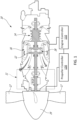
- FIG. 1 illustrates a gas turbine engine 10 of a type preferably provided for use in subsonic flight, generally comprising in serial flow communication a compressor section 14 for pressurizing ambient air, a combustor 16 in which the compressed air is mixed with fuel and ignited for generating an annular stream of hot combustion gases, and a turbine section 18 for extracting energy from the combustion gases.
- a low pressure (LP) turbine 12 drives, via a reduction gear box (RGB), a propeller 19 having propeller blades 17 for providing thrust to the aircraft.
- RGB reduction gear box
- the propeller 19 may be a broader propeller system, and may include various components related to the propeller itself, including components which assist in regulating the operation of the propeller 19.
- An oil system 11 is provided for the gas turbine engine 10, and provides lubrication for the rotating components of the gas turbine engine 10, which include bearings for the rotating turbomachinery (e.g. the compressors, turbines, shafts, and gears), the RGB and the propeller control systems, etc.
- the rotating turbomachinery e.g. the compressors, turbines, shafts, and gears
- the RGB and the propeller control systems etc.
- an engine controller 110 is coupled to the engine 10 for controlling operation of the engine 10.
- a propeller controller 120 is coupled to the propeller 19 for controlling operation of the propeller 19.
- the engine controller 110 and the propeller controller 120 may be communicatively coupled to one another via any suitable wired and/or wireless means, and may exchange signals, information, and the like to collaboratively operate the engine 10 and the propeller 19.
- the engine controller 110 and the propeller 120 are communicatively coupled via one or more electrical, optical, and/or electromagnetic communication channels.
- the engine controller 110 and the propeller 120 may be communicatively coupled via one or more hydraulic and/or mechanical communication channels.
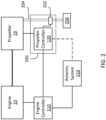
- FIG. 2 a schematic representation of the engine 10 and the propeller 19 is illustrated.
- the engine controller 110 and the propeller controller 120 are coupled to one another.
- the engine controller 110, and in some embodiments the propeller controller 120 may be connected to an external system, which may be an avionics system 210, in applications in which the engine 10 forms part of an aircraft, or a different external system in other applications.
- an external system which may be an avionics system 210, in applications in which the engine 10 forms part of an aircraft, or a different external system in other applications.
- the propeller controller 120 forms part of and assists in operating a propeller control unit (PCU), illustrated here at 200.
- the PCU 200 includes a valve 202 which is controlled by the propeller controller 120.
- the valve 202 is an electrohydraulic servo valve (EHSV).
- EHSV electrohydraulic servo valve
- the valve 202 modulates a flow of a fluid, for instance oil, which flows to the propeller 19 from a reservoir 206 via a conduit 204.
- the valve 202 controls the rate at which oil flows from the reservoir 206 to the propeller 19.
- the flow of oil through the conduit 204 governs the operation of the propeller 19, including modifying the pitch angle of the propeller blades 17 (sometimes referred to as the beta angle) and the rotational speed of the propeller 19.
- the particular response of the propeller 19 to increasing or decreasing the oil flow to the propeller 19, by increasing or decreasing the degree to which the valve 202 is open may vary from one application to the next.
- increasing the oil flow to the propeller 19 causes the propeller blades 17 to transfer to a lower pitch angle, such that, when the propeller 19 is operating in a forward (i.e., positive) range of pitch angles, the propeller 19 experiences acceleration (i.e., an increase in rotational speed).
- decreasing the oil flow to the propeller 19 causes the propeller blades 17 to transfer to a higher pitch angle, so that, when the propeller 19 is operating in a forward (i.e., positive) range of pitch angles, the propeller 19 experiences deceleration (i.e., a decrease in rotational speed).
- deceleration i.e., a decrease in rotational speed
- the valve 202 may malfunction, for instance due to wear, contamination, the presence of debris, or the like, causing requests to change in the pitch angle of the propeller blades 17 to fail.
- Other issues resulting from faulty behaviour of the valve 202 include governing speed drift, propeller speed overshoots, and the like, which in turn can trigger accommodation systems of the aircraft. It should also be noted that the viscosity of the fluid (e.g.
- the present disclosure provides, inter alia, methods and systems for validating PCUs, including validating the response time and/or operation of the valve 202.
- operability of the valve 202, or other valves of the PCU 200 may be validated before a flight mission in situations in which the engine 10 and/or an associated aircraft have not been operated for a certain period of time.
- the engine start sequence for the engine 10 is composed of a plurality of operations, including validation of the PCU 200, which are performed in a particular order following an engine start request from an operator of the engine 10 and/or of an aircraft of which the engine 10 forms part.
- validation of the PCU 200 may be performed in response to the operator issuing the engine start request, for example to the engine controller 110.
- Performing validation of the PCU 200 during the engine start sequence may serve to detect failure of the PCU 200 prior to a period of extended operation which would be hindered by malfunction of the PCU 200.
- validation of the PCU 200 is performed as part of a routine maintenance procedure. Other uses cases are also considered.
- validation of the PCU 200 is performed in response to receiving a PCU validation request from the operator, which may be received, for instance, at the propeller controller 120.
- a manufacturer, designer, regulator, or other relevant authority may specify that PCU validation should be performed at certain predetermined engine parameters, and the operator of the engine 10 may be trained to request PCU validation only when the predetermined engine parameters are satisfied.
- the engine parameters for PCU validation may specify a particular engine temperature, engine power output, engine speed (e.g., a rotational speed of an output shaft of the engine 10), propeller rotational speed, etc., or any suitable combination thereof.
- the engine controller 110 may prompt the operator to perform the PCU validation when the engine controller 110 determines that the predetermined engine parameters are satisfied.
- validation of the PCU 200 in the context of a wind turbine may be prompted, or automatically be performed, once the propeller 19 has been active for a predetermined amount of time, or when a temperature of the oil flowing through conduit 204 reaches a predetermined temperature.
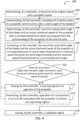
- the method 400 comprises issuing, by the controller, a warning signal to the operator of the propeller 19.
- the warning signal may include an indication that the PCU 200 was not validated, of a degree of failure of the PCU 200, of a recommended time delay before attempting revalidation of the PCU 200, or any other suitable information.
- the warning signal may be presented to the operator via a display, which may include a screen, a warning light, an audio device, or the like, and which may form part of the avionics system 210.
- the method 400 comprises preventing operation of a system associated with the propeller 19 in at least one operating regime.
- step 414 may include preventing a component of the aircraft from operating in a different operating regime, for instance preventing the engine 10 from entering a takeoff operating regime, or the like.
- subsequent attempts to validate the PCU 200 may be performed, for instance by repeating one or more of the steps of the method 400.
- the method 400 may thus return to a previous step, for instance step 404, from step 412 or step 414.
- a subsequent actuation of the valve 202 is commanded and a subsequent pitch angle of the blades 17 (and/or subsequent rotational speed of the propeller 19) is determined.
- the subsequent blade angle (and/or subsequent rotational speed) is compared to the pitch angle threshold (and/or rotational speed threshold) to determine whether the PCU 200 is validated.
- a subsequent warning signal may be issued, which may, for instance, include a recommended maintenance action for the PCU 200.
- the PCU 200 is validated, and a validation signal is issued, for instance for presentation to the operator.
- the methods and systems for validating a propeller control unit described herein may be implemented in a high level procedural or object oriented programming or scripting language, or a combination thereof, to communicate with or assist in the operation of a computer system, for example the computing device 300.
- the methods and systems described herein may be implemented in assembly or machine language.
- the language may be a compiled or interpreted language.
- Program code for implementing the methods and systems described herein may be stored on a storage media or a device, for example a ROM, a magnetic disk, an optical disc, a flash drive, or any other suitable storage media or device.
- the program code may be readable by a general or special-purpose programmable computer for configuring and operating the computer when the storage media or device is read by the computer to perform the procedures described herein.
- Embodiments of the methods and systems described herein may also be considered to be implemented by way of a non-transitory computer-readable storage medium having a computer program stored thereon.
- the computer program may comprise computer-readable instructions which cause a computer, or more specifically the processing unit 312 of the computing device 300, to operate in a specific and predefined manner to perform the functions described herein, for example those described in the method 400.
- Computer-executable instructions may be in many forms, including program modules, executed by one or more computers or other devices.
- program modules include routines, programs, objects, components, data structures, etc., that perform particular tasks or implement particular abstract data types.
- functionality of the program modules may be combined or distributed as desired in various embodiments.
- the embodiments described herein are implemented by physical computer hardware, including computing devices, servers, receivers, transmitters, processors, memory, displays, and networks.
- the embodiments described herein provide useful physical machines and particularly configured computer hardware arrangements.
- the embodiments described herein are directed to electronic machines and methods implemented by electronic machines adapted for processing and transforming electromagnetic signals which represent various types of information.
- the embodiments described herein pervasively and integrally relate to machines, and their uses; and the embodiments described herein have no meaning or practical applicability outside their use with computer hardware, machines, and various hardware components. Substituting the physical hardware particularly configured to implement various acts for non-physical hardware, using mental steps for example, may substantially affect the way the embodiments work.
- the technical solution of embodiments may be in the form of a software product.
- the software product may be stored in a non-volatile or non-transitory storage medium, which can be a compact disk read-only memory (CD-ROM), a USB flash disk, or a removable hard disk.
- the software product includes a number of instructions that enable a computer device (personal computer, server, or network device) to execute the methods provided by the embodiments.
Landscapes
- Engineering & Computer Science (AREA)
- Aviation & Aerospace Engineering (AREA)
- Mechanical Engineering (AREA)
- General Engineering & Computer Science (AREA)
- Business, Economics & Management (AREA)
- Emergency Management (AREA)
- Physics & Mathematics (AREA)
- General Physics & Mathematics (AREA)
- Automation & Control Theory (AREA)
- Control Of Turbines (AREA)
Claims (15)
- Procédé de validation d'une unité de commande d'hélice (200) associée à une hélice (19) ayant des pales (17), le procédé comprenant :la commande, par un dispositif de commande (110, 120), de l'actionnement d'une vanne de commande (202) de l'unité de commande d'hélice (200) pour atteindre un degré prédéterminé d'ouverture ou de fermeture de la vanne de commande (202) afin de provoquer un changement dans un écoulement de fluide vers l'hélice (19) de manière à modifier un angle de pas des pales (17) pour un angle de pas commandé et à commander une vitesse de rotation de l'hélice (19) pour une vitesse de rotation commandée ;la détermination, au niveau du dispositif de commande (110, 120) et par l'intermédiaire d'un système de détection au niveau de l'hélice (19), de l'un d'un angle de pas réel des pales (17) et d'une vitesse de rotation réelle de l'hélice (19) après qu'un délai prédéterminé s'est écoulé depuis la commande de l'actionnement de la vanne de commande (202), le délai prédéterminé correspondant à un temps prévu nécessaire pour que la vanne de commande (202) atteigne le degré prédéterminé d'ouverture ou de fermeture ;la comparaison, au niveau du dispositif de commande (110, 120), de l'un de l'angle de pas réel des pales (17) et de la vitesse de rotation réelle de l'hélice (19) à un seuil correspondant d'un seuil d'angle de pas et d'un seuil de vitesse de rotation, le seuil d'angle de pas et le seuil de vitesse de rotation étant sur la base de l'angle de pas commandé ; etl'émission, par le dispositif de commande (110, 120), d'un signal d'avertissement en réponse à la détermination de l'un de l'angle de pas réel qui n'atteint pas le seuil d'angle de pas et de la vitesse de rotation réelle qui n'atteint pas le seuil de vitesse de rotation.
- Procédé selon la revendication 1, dans lequel la comparaison de l'un de l'angle de pas réel des pales (17) et de la vitesse de rotation réelle de l'hélice (19) au seuil correspondant du seuil d'angle de pas et du seuil de vitesse de rotation comprend l'une de :la comparaison de l'angle de pas réel des pales (17) à l'un parmi l'angle de pas commandé, une valeur sur la base de l'angle de pas commandé, et une plage de valeurs sur la base de l'angle de pas commandé ; etla comparaison de la vitesse de rotation réelle de l'hélice (19) à l'une parmi la vitesse de rotation commandées sur la base de l'angle de pas commandé, une valeur sur la base de la vitesse de rotation commandée, et une plage de valeurs sur la base de la vitesse de rotation commandée.
- Procédé selon la revendication 1 ou 2, dans lequel la commande d'actionnement de la vanne de commande (202) est effectuée en réponse à l'obtention d'une demande d'exécution d'une séquence de démarrage pour un moteur (10) associé à l'hélice (19),
comprenant optionnellement la détermination, au niveau du dispositif de commande (110, 120), d'au moins l'une d'une vitesse de moteur du moteur (10) et d'une vitesse d'hélice de l'hélice (19), et l'exécution de la commande de l'actionnement de la vanne de commande (202) en réponse à la détermination du fait que l'au moins l'une de la vitesse de moteur et de la vitesse d'hélice est supérieure à un seuil de vitesse pendant la séquence de démarrage. - Procédé selon l'une quelconque des revendications 1 à 3, comprenant :l'obtention, au niveau du dispositif de commande (110, 120) et suite à l'émission du signal d'avertissement, d'une demande de revalidation de l'unité de commande d'hélice (200) ;en réponse à l'obtention de la demande de revalidation de l'unité de commande d'hélice (200), la commande, par le dispositif de commande (110, 120), d'un actionnement ultérieur de la vanne de commande (202) afin de modifier l'angle de pas des pales (17) ;la détermination, au niveau du dispositif de commande (110, 120), de l'un d'un angle de pas ultérieur des pales et d'une vitesse de rotation ultérieure de l'hélice après que le délai prédéterminé s'est écoulé depuis la commande de l'actionnement ultérieur de la vanne de commande ;la comparaison, au niveau du dispositif de commande (110, 120), de l'un de l'angle de pas ultérieur des pales (17) et de la vitesse de rotation ultérieure de l'hélice (19) au seuil correspondant du seuil d'angle de pas et du seuil de vitesse de rotation ; etl'émission, par le dispositif de commande (110, 120), d'un signal d'avertissement ultérieur en réponse à la détermination de l'un de l'angle de pas ultérieur qui n'atteint pas le seuil d'angle de pas et de la vitesse de rotation ultérieure qui n'atteint pas le seuil de vitesse de rotation.
- Procédé selon la revendication 4, comprenant l'émission, par le dispositif de commande (110, 120), d'un signal de validation en réponse à la détermination de l'un de l'angle de pas ultérieur qui atteint le seuil d'angle de pas et de la vitesse de rotation ultérieure qui atteint le seuil de vitesse de rotation.
- Procédé selon la revendication 4 ou 5, dans lequel l'émission du signal d'avertissement comprend la fourniture d'une indication d'un temps de fonctionnement recommandé de l'hélice (19) avant d'émettre la demande de revalidation de l'unité de commande d'hélice (200).
- Procédé selon la revendication 4, 5 ou 6, dans lequel l'émission du signal d'avertissement ultérieur comprend la fourniture d'une indication d'une action de maintenance à effectuer sur l'unité de commande d'hélice (200).
- Procédé selon l'une quelconque revendication précédente, comprenant la prévention, par le dispositif de commande (110, 120), du fonctionnement d'un composant d'un aéronef associé à l'hélice (19) dans au moins un régime de fonctionnement, en réponse à la détermination de l'un de l'angle de pas réel qui n'atteint pas le seuil d'angle de pas et de la vitesse de rotation réelle qui n'atteint pas le seuil de vitesse de rotation,
optionnellement, dans lequel la prévention du fonctionnement du composant de l'aéronef associé à l'hélice (19) dans l'au moins un régime de fonctionnement comprend la prévention du fonctionnement d'un moteur (10) de l'aéronef dans l'au moins un régime de fonctionnement. - Procédé selon l'une quelconque revendication précédente, comprenant l'émission, par le dispositif de commande (110, 120), d'un signal de validation en réponse à la détermination de l'un de l'angle de pas réel qui atteint le seuil d'angle de pas et de la vitesse de rotation réelle qui atteint le seuil de vitesse de rotation.
- Système (300) de validation d'une unité de commande d'hélice (200) associée à une hélice (19) ayant des pales (17), le système comprenant :un système de détection destiné à déterminer un angle de pas des pales (17) et une vitesse de rotation de l'hélice (19) ;une unité de traitement (312) ; etun support lisible par ordinateur non transitoire (314) sur lequel sont stockées des instructions (316) exécutables par l'unité de traitement (312) afin d'amener le système (300) à effectuer :la commande de l'actionnement d'une vanne de commande (202) de l'unité de commande d'hélice (200) pour atteindre un degré prédéterminé d'ouverture ou de fermeture de la vanne de commande (202) afin de provoquer un changement dans un écoulement de fluide vers l'hélice (19) de manière à modifier un angle de pas des pales (17) pour un angle de pas commandé et à commander une vitesse de rotation de l'hélice (19) pour une vitesse de rotation commandée ;la détermination de l'un d'un angle de pas réel des pales (17) et d'une vitesse de rotation réelle de l'hélice (19) après qu'un délai prédéterminé s'est écoulé depuis la commande de l'actionnement de la vanne de commande (202), le délai prédéterminé correspondant à un temps prévu nécessaire pour que la vanne de commande (202) atteigne le degré prédéterminé d'ouverture ou de fermeture ;la comparaison de l'un de l'angle de pas réel des pales (17) et de la vitesse de rotation réelle de l'hélice (19) à un seuil correspondant d'un seuil d'angle de pas et d'un seuil de vitesse de rotation, le seuil d'angle de pas et le seuil de vitesse de rotation étant sur la base de l'angle de pas commandé ; etl'émission d'un signal d'avertissement en réponse à la détermination de l'un de l'angle de pas réel qui n'atteint pas le seuil d'angle de pas et de la vitesse de rotation réelle qui n'atteint pas le seuil de vitesse de rotation.
- Système selon la revendication 10, dans lequel la comparaison de l'un de l'angle de pas réel des pales (17) et de la vitesse de rotation réelle de l'hélice (19) au seuil correspondant du seuil d'angle de pas et du seuil de vitesse de rotation comprend l'une de :la comparaison de l'angle de pas réel des pales (17) à l'un parmi l'angle de pas commandé, une valeur sur la base de l'angle de pas commandé, et une plage de valeurs sur la base de l'angle de pas commandé ; etla comparaison de la vitesse de rotation réelle de l'hélice (19) à l'une parmi la vitesse de rotation commandées sur la base de l'angle de pas commandé, une valeur sur la base de la vitesse de rotation commandée, et une plage de valeurs sur la base de la vitesse de rotation commandée.
- Système selon la revendication 10 ou 11, dans lequel la commande d'actionnement de la vanne de commande (202) est effectuée en réponse à l'obtention d'une demande d'exécution d'une séquence de démarrage pour un moteur (10) associé à l'hélice (19),
optionnellement, dans lequel les instructions peuvent être exécutées afin de déterminer au moins l'une d'une vitesse de moteur du moteur (10) et d'une vitesse d'hélice de l'hélice (19), et l'exécution de la commande de l'actionnement de la vanne de commande (202) en réponse à la détermination du fait que l'au moins l'une de la vitesse de moteur et de la vitesse d'hélice est supérieure à un seuil de vitesse pendant la séquence de démarrage. - Système selon l'une quelconque des revendications 10 à 12, dans lequel les instructions (316) peuvent être exécutées afin de :obtenir, suite à l'émission du signal d'avertissement, une demande de revalidation de l'unité de commande d'hélice (200) ;en réponse à l'obtention de la demande de revalidation de l'unité de commande d'hélice (200), commander un actionnement ultérieur de la vanne de commande (202) afin de modifier l'angle de pas des pales (17) ;déterminer l'un d'un angle de pas ultérieur des pales (17) et d'une vitesse de rotation ultérieure de l'hélice (19) après que le délai prédéterminé s'est écoulé depuis la commande de l'actionnement ultérieur de la vanne de commande (202) ;comparer l'un de l'angle de pas ultérieur des pales (17) et de la vitesse de rotation ultérieure de l'hélice (19) au seuil correspondant du seuil d'angle de pas et du seuil de vitesse de rotation ; etémettre un signal d'avertissement ultérieur en réponse à la détermination de l'un de l'angle de pas ultérieur qui n'atteint pas le seuil d'angle de pas et de la vitesse de rotation ultérieure qui n'atteint pas le seuil de vitesse de rotation.
- Système selon l'une quelconque des revendications 10 à 13, dans lequel les instructions (316) peuvent être exécutées afin d'empêcher le fonctionnement d'un composant d'un aéronef associé à l'hélice (19) dans au moins un régime de fonctionnement, en réponse à la détermination de l'un de l'angle de pas réel qui n'atteint pas le seuil d'angle de pas et de la vitesse de rotation réelle qui n'atteint pas le seuil de vitesse de rotation.
- Système selon l'une quelconque des revendications 10 à 14, dans lequel les instructions (316) peuvent être exécutées afin d'émettre un signal de validation en réponse à la détermination de l'un de l'angle de pas réel qui atteint le seuil d'angle de pas et de la vitesse de rotation réelle qui atteint le seuil de vitesse de rotation.
Applications Claiming Priority (1)
| Application Number | Priority Date | Filing Date | Title |
|---|---|---|---|
| US17/164,076 US11702943B2 (en) | 2021-02-01 | 2021-02-01 | Propeller control unit validation |
Publications (2)
| Publication Number | Publication Date |
|---|---|
| EP4035997A1 EP4035997A1 (fr) | 2022-08-03 |
| EP4035997B1 true EP4035997B1 (fr) | 2025-07-02 |
Family
ID=80119311
Family Applications (1)
| Application Number | Title | Priority Date | Filing Date |
|---|---|---|---|
| EP22154513.0A Active EP4035997B1 (fr) | 2021-02-01 | 2022-02-01 | Validation d'unité de commande d'hélice |
Country Status (3)
| Country | Link |
|---|---|
| US (1) | US11702943B2 (fr) |
| EP (1) | EP4035997B1 (fr) |
| CA (1) | CA3147198A1 (fr) |
Families Citing this family (4)
| Publication number | Priority date | Publication date | Assignee | Title |
|---|---|---|---|---|
| JP7789645B2 (ja) * | 2022-09-09 | 2025-12-22 | 本田技研工業株式会社 | 推力発生装置 |
| EP4458677B1 (fr) | 2023-05-04 | 2026-04-15 | Ratier-Figeac SAS | Système de protection de hélice et procédé d'operation |
| US12486023B2 (en) | 2024-01-09 | 2025-12-02 | Pratt & Whitney Canada Corp. | Model-based speed governing for variable-pitch propeller |
| CN120889669B (zh) * | 2025-09-30 | 2026-01-06 | 壹通无人机系统有限公司 | 无人机发动机起动方法及系统 |
Family Cites Families (20)
| Publication number | Priority date | Publication date | Assignee | Title |
|---|---|---|---|---|
| US5284418A (en) * | 1991-07-29 | 1994-02-08 | Toyota Jidosha Kabushiki Kaisha | Electric pitch control apparatus for variable pitch propeller capable of controlling the pitch angle based instantaneous operational conditions of the propeller |
| US6059528A (en) * | 1996-11-22 | 2000-05-09 | United Technologies Corporation | Electronic propeller control system |
| US5997250A (en) | 1997-01-09 | 1999-12-07 | Catercopters, Llc | Method and apparatus for controlling pitch of an aircraft propeller |
| US7873445B2 (en) * | 2007-03-26 | 2011-01-18 | Bell Helicopter Textron, Inc. | Governor for a rotor with a variable maximum collective pitch |
| US9476312B2 (en) * | 2013-03-15 | 2016-10-25 | Bell Helicopter Textron Inc. | Swashplateless active blade pitch control with a mechanical delta-3 restraint having an instantaneous blade pitch-flap coupling response |
| FR3011048B1 (fr) | 2013-09-24 | 2016-05-13 | Snecma | Dispositif d'alimentation en fluide hydraulique d'un verin et mecanisme de commande de pas des pales d'une helice de turbomoteur comportant le verin |
| US10487682B2 (en) * | 2015-05-15 | 2019-11-26 | Pratt & Whitney Canada Corp. | Automated propeller feather testing |
| PL226824B1 (pl) | 2015-09-07 | 2017-09-29 | Gen Electric | Układ isposób regulacji skoku smigła |
| US10994836B2 (en) * | 2015-12-11 | 2021-05-04 | Amazon Technologies, Inc. | Feathering propeller clutch mechanisms |
| US10501169B2 (en) | 2016-06-17 | 2019-12-10 | Pratt & Whitney Canada Corp. | Propeller blade angle control system |
| FR3055002B1 (fr) | 2016-08-10 | 2022-03-04 | Safran Aircraft Engines | Systeme de changement de pas equipe de moyens d'alimentation fluidique d'un moyen de commande et turbomachine correspondante |
| US10486827B2 (en) | 2016-08-17 | 2019-11-26 | Pratt & Whitney Canada Corp. | Apparatus and methods for aircraft propeller control |
| EP3434585B1 (fr) | 2017-07-28 | 2021-04-14 | General Electric Company | Système de commande d'hélice pour un aéronef |
| US11312476B2 (en) | 2017-09-25 | 2022-04-26 | Woodward, Inc. | Propeller control unit |
| EP3466806B1 (fr) * | 2017-10-09 | 2021-07-28 | MT-Propeller Entwicklung GmbH | Unité d'hélice à pas réglable pourvue d'un dispositif de commande hydraulique |
| EP3543113B1 (fr) * | 2018-03-23 | 2021-05-26 | Ge Avio S.r.l. | Système et procédé d'amélioration de la réponse de l'hélice pendant la transition de la configuration du sol au vol pour un moteur turbopropulseur |
| US10961921B2 (en) | 2018-09-19 | 2021-03-30 | Pratt & Whitney Canada Corp. | Model-based control system and method for a turboprop engine |
| US11964750B2 (en) * | 2019-03-07 | 2024-04-23 | General Electric Company | Propeller speed overshoot preventing logic |
| US11059567B2 (en) | 2019-05-21 | 2021-07-13 | Pratt & Whitney Canada Corp. | Method of controlling a propeller with two-position solenoid |
| US11738862B2 (en) * | 2020-01-28 | 2023-08-29 | Overair, Inc. | Fail-operational vtol aircraft |
-
2021
- 2021-02-01 US US17/164,076 patent/US11702943B2/en active Active
-
2022
- 2022-01-31 CA CA3147198A patent/CA3147198A1/fr active Pending
- 2022-02-01 EP EP22154513.0A patent/EP4035997B1/fr active Active
Also Published As
| Publication number | Publication date |
|---|---|
| EP4035997A1 (fr) | 2022-08-03 |
| US11702943B2 (en) | 2023-07-18 |
| US20220243600A1 (en) | 2022-08-04 |
| CA3147198A1 (fr) | 2022-08-01 |
Similar Documents
| Publication | Publication Date | Title |
|---|---|---|
| EP4035997B1 (fr) | Validation d'unité de commande d'hélice | |
| EP3738874B1 (fr) | Système et procédé de fonctionnement d'un giravion | |
| US11408357B2 (en) | Engine and propeller control system | |
| EP3741666B1 (fr) | Procédé de commande d'une hélice avec solénoïde à deux positions | |
| CA3077511C (fr) | Procede et systeme de fonctionnement du groupe motopropulseur pour aeronef | |
| US11313286B2 (en) | Integrated propeller and engine controller | |
| US20200232395A1 (en) | Method and system for operating a gas turbine engine coupled to an aircraft propeller | |
| US11852083B2 (en) | Engine and propeller control system | |
| US12078074B2 (en) | System and method for detecting an uncommanded or uncontrollable high thrust event in an aircraft | |
| EP3855004B1 (fr) | Procédés et systèmes de démarrage d'un moteur à turbine à gaz | |
| EP3705398B1 (fr) | Procédé et système pour faire fonctionner un moteur dans un aéronef multi-moteur | |
| CA3147207A1 (fr) | Detection des anomalies d'un regulateur de carburant | |
| CA3060755A1 (fr) | Controleur d`helice et de moteur integre | |
| EP3904660B1 (fr) | Système et procédé de détection d'un événement d'arbre sur un moteur à turbine à gaz | |
| EP4459117A2 (fr) | Procédé et système de régulation d'un moteur à faible puissance | |
| EP4368500B1 (fr) | Systèmes et procédés de commande de pression de fluide d'unité de commande d'hélice | |
| EP4067635B1 (fr) | Commande d'un turbopropulseur pour le redémarrage en vol |
Legal Events
| Date | Code | Title | Description |
|---|---|---|---|
| PUAI | Public reference made under article 153(3) epc to a published international application that has entered the european phase |
Free format text: ORIGINAL CODE: 0009012 |
|
| STAA | Information on the status of an ep patent application or granted ep patent |
Free format text: STATUS: THE APPLICATION HAS BEEN PUBLISHED |
|
| AK | Designated contracting states |
Kind code of ref document: A1 Designated state(s): AL AT BE BG CH CY CZ DE DK EE ES FI FR GB GR HR HU IE IS IT LI LT LU LV MC MK MT NL NO PL PT RO RS SE SI SK SM TR |
|
| STAA | Information on the status of an ep patent application or granted ep patent |
Free format text: STATUS: REQUEST FOR EXAMINATION WAS MADE |
|
| 17P | Request for examination filed |
Effective date: 20230127 |
|
| RBV | Designated contracting states (corrected) |
Designated state(s): AL AT BE BG CH CY CZ DE DK EE ES FI FR GB GR HR HU IE IS IT LI LT LU LV MC MK MT NL NO PL PT RO RS SE SI SK SM TR |
|
| STAA | Information on the status of an ep patent application or granted ep patent |
Free format text: STATUS: EXAMINATION IS IN PROGRESS |
|
| 17Q | First examination report despatched |
Effective date: 20231121 |
|
| GRAP | Despatch of communication of intention to grant a patent |
Free format text: ORIGINAL CODE: EPIDOSNIGR1 |
|
| STAA | Information on the status of an ep patent application or granted ep patent |
Free format text: STATUS: GRANT OF PATENT IS INTENDED |
|
| INTG | Intention to grant announced |
Effective date: 20250129 |
|
| GRAS | Grant fee paid |
Free format text: ORIGINAL CODE: EPIDOSNIGR3 |
|
| GRAA | (expected) grant |
Free format text: ORIGINAL CODE: 0009210 |
|
| STAA | Information on the status of an ep patent application or granted ep patent |
Free format text: STATUS: THE PATENT HAS BEEN GRANTED |
|
| AK | Designated contracting states |
Kind code of ref document: B1 Designated state(s): AL AT BE BG CH CY CZ DE DK EE ES FI FR GB GR HR HU IE IS IT LI LT LU LV MC MK MT NL NO PL PT RO RS SE SI SK SM TR |
|
| REG | Reference to a national code |
Ref country code: GB Ref legal event code: FG4D |
|
| REG | Reference to a national code |
Ref country code: CH Ref legal event code: EP |
|
| REG | Reference to a national code |
Ref country code: DE Ref legal event code: R096 Ref document number: 602022016653 Country of ref document: DE |
|
| REG | Reference to a national code |
Ref country code: IE Ref legal event code: FG4D |
|
| REG | Reference to a national code |
Ref country code: NL Ref legal event code: MP Effective date: 20250702 |
|
| PG25 | Lapsed in a contracting state [announced via postgrant information from national office to epo] |
Ref country code: PT Free format text: LAPSE BECAUSE OF FAILURE TO SUBMIT A TRANSLATION OF THE DESCRIPTION OR TO PAY THE FEE WITHIN THE PRESCRIBED TIME-LIMIT Effective date: 20251103 |
|
| PG25 | Lapsed in a contracting state [announced via postgrant information from national office to epo] |
Ref country code: NL Free format text: LAPSE BECAUSE OF FAILURE TO SUBMIT A TRANSLATION OF THE DESCRIPTION OR TO PAY THE FEE WITHIN THE PRESCRIBED TIME-LIMIT Effective date: 20250702 |
|
| REG | Reference to a national code |
Ref country code: AT Ref legal event code: MK05 Ref document number: 1808977 Country of ref document: AT Kind code of ref document: T Effective date: 20250702 |
|
| PG25 | Lapsed in a contracting state [announced via postgrant information from national office to epo] |
Ref country code: IS Free format text: LAPSE BECAUSE OF FAILURE TO SUBMIT A TRANSLATION OF THE DESCRIPTION OR TO PAY THE FEE WITHIN THE PRESCRIBED TIME-LIMIT Effective date: 20251102 |
|
| PG25 | Lapsed in a contracting state [announced via postgrant information from national office to epo] |
Ref country code: NO Free format text: LAPSE BECAUSE OF FAILURE TO SUBMIT A TRANSLATION OF THE DESCRIPTION OR TO PAY THE FEE WITHIN THE PRESCRIBED TIME-LIMIT Effective date: 20251002 |
|
| REG | Reference to a national code |
Ref country code: LT Ref legal event code: MG9D |
|
| PG25 | Lapsed in a contracting state [announced via postgrant information from national office to epo] |
Ref country code: AT Free format text: LAPSE BECAUSE OF FAILURE TO SUBMIT A TRANSLATION OF THE DESCRIPTION OR TO PAY THE FEE WITHIN THE PRESCRIBED TIME-LIMIT Effective date: 20250702 |
|
| PG25 | Lapsed in a contracting state [announced via postgrant information from national office to epo] |
Ref country code: FI Free format text: LAPSE BECAUSE OF FAILURE TO SUBMIT A TRANSLATION OF THE DESCRIPTION OR TO PAY THE FEE WITHIN THE PRESCRIBED TIME-LIMIT Effective date: 20250702 |
|
| PG25 | Lapsed in a contracting state [announced via postgrant information from national office to epo] |
Ref country code: HR Free format text: LAPSE BECAUSE OF FAILURE TO SUBMIT A TRANSLATION OF THE DESCRIPTION OR TO PAY THE FEE WITHIN THE PRESCRIBED TIME-LIMIT Effective date: 20250702 |
|
| PG25 | Lapsed in a contracting state [announced via postgrant information from national office to epo] |
Ref country code: GR Free format text: LAPSE BECAUSE OF FAILURE TO SUBMIT A TRANSLATION OF THE DESCRIPTION OR TO PAY THE FEE WITHIN THE PRESCRIBED TIME-LIMIT Effective date: 20251003 |
|
| PG25 | Lapsed in a contracting state [announced via postgrant information from national office to epo] |
Ref country code: SE Free format text: LAPSE BECAUSE OF FAILURE TO SUBMIT A TRANSLATION OF THE DESCRIPTION OR TO PAY THE FEE WITHIN THE PRESCRIBED TIME-LIMIT Effective date: 20250702 Ref country code: CZ Free format text: LAPSE BECAUSE OF FAILURE TO SUBMIT A TRANSLATION OF THE DESCRIPTION OR TO PAY THE FEE WITHIN THE PRESCRIBED TIME-LIMIT Effective date: 20250702 |
|
| PG25 | Lapsed in a contracting state [announced via postgrant information from national office to epo] |
Ref country code: LV Free format text: LAPSE BECAUSE OF FAILURE TO SUBMIT A TRANSLATION OF THE DESCRIPTION OR TO PAY THE FEE WITHIN THE PRESCRIBED TIME-LIMIT Effective date: 20250702 |
|
| PG25 | Lapsed in a contracting state [announced via postgrant information from national office to epo] |
Ref country code: BG Free format text: LAPSE BECAUSE OF FAILURE TO SUBMIT A TRANSLATION OF THE DESCRIPTION OR TO PAY THE FEE WITHIN THE PRESCRIBED TIME-LIMIT Effective date: 20250702 Ref country code: PL Free format text: LAPSE BECAUSE OF FAILURE TO SUBMIT A TRANSLATION OF THE DESCRIPTION OR TO PAY THE FEE WITHIN THE PRESCRIBED TIME-LIMIT Effective date: 20250702 |
|
| PG25 | Lapsed in a contracting state [announced via postgrant information from national office to epo] |
Ref country code: RS Free format text: LAPSE BECAUSE OF FAILURE TO SUBMIT A TRANSLATION OF THE DESCRIPTION OR TO PAY THE FEE WITHIN THE PRESCRIBED TIME-LIMIT Effective date: 20251002 |
|
| PG25 | Lapsed in a contracting state [announced via postgrant information from national office to epo] |
Ref country code: ES Free format text: LAPSE BECAUSE OF FAILURE TO SUBMIT A TRANSLATION OF THE DESCRIPTION OR TO PAY THE FEE WITHIN THE PRESCRIBED TIME-LIMIT Effective date: 20250702 |
|
| PG25 | Lapsed in a contracting state [announced via postgrant information from national office to epo] |
Ref country code: SM Free format text: LAPSE BECAUSE OF FAILURE TO SUBMIT A TRANSLATION OF THE DESCRIPTION OR TO PAY THE FEE WITHIN THE PRESCRIBED TIME-LIMIT Effective date: 20250702 |
|
| PGFP | Annual fee paid to national office [announced via postgrant information from national office to epo] |
Ref country code: GB Payment date: 20260121 Year of fee payment: 5 |
|
| PG25 | Lapsed in a contracting state [announced via postgrant information from national office to epo] |
Ref country code: DK Free format text: LAPSE BECAUSE OF FAILURE TO SUBMIT A TRANSLATION OF THE DESCRIPTION OR TO PAY THE FEE WITHIN THE PRESCRIBED TIME-LIMIT Effective date: 20250702 |
|
| PGFP | Annual fee paid to national office [announced via postgrant information from national office to epo] |
Ref country code: DE Payment date: 20260121 Year of fee payment: 5 |
|
| PG25 | Lapsed in a contracting state [announced via postgrant information from national office to epo] |
Ref country code: IT Free format text: LAPSE BECAUSE OF FAILURE TO SUBMIT A TRANSLATION OF THE DESCRIPTION OR TO PAY THE FEE WITHIN THE PRESCRIBED TIME-LIMIT Effective date: 20250702 |
|
| PGFP | Annual fee paid to national office [announced via postgrant information from national office to epo] |
Ref country code: FR Payment date: 20260121 Year of fee payment: 5 |
|
| PG25 | Lapsed in a contracting state [announced via postgrant information from national office to epo] |
Ref country code: SK Free format text: LAPSE BECAUSE OF FAILURE TO SUBMIT A TRANSLATION OF THE DESCRIPTION OR TO PAY THE FEE WITHIN THE PRESCRIBED TIME-LIMIT Effective date: 20250702 Ref country code: EE Free format text: LAPSE BECAUSE OF FAILURE TO SUBMIT A TRANSLATION OF THE DESCRIPTION OR TO PAY THE FEE WITHIN THE PRESCRIBED TIME-LIMIT Effective date: 20250702 |