EP4036386B1 - Moteur à combustion interne pour véhicule automobile, en particulier pour véhicule à moteur, ainsi que véhicule automobile, en particulier véhicule à moteur - Google Patents
Moteur à combustion interne pour véhicule automobile, en particulier pour véhicule à moteur, ainsi que véhicule automobile, en particulier véhicule à moteur Download PDFInfo
- Publication number
- EP4036386B1 EP4036386B1 EP22151298.1A EP22151298A EP4036386B1 EP 4036386 B1 EP4036386 B1 EP 4036386B1 EP 22151298 A EP22151298 A EP 22151298A EP 4036386 B1 EP4036386 B1 EP 4036386B1
- Authority
- EP
- European Patent Office
- Prior art keywords
- exhaust gas
- catalytic converter
- turbine wheel
- combustion engine
- internal combustion
- Prior art date
- Legal status (The legal status is an assumption and is not a legal conclusion. Google has not performed a legal analysis and makes no representation as to the accuracy of the status listed.)
- Active
Links
Images



Classifications
-
- F—MECHANICAL ENGINEERING; LIGHTING; HEATING; WEAPONS; BLASTING
- F01—MACHINES OR ENGINES IN GENERAL; ENGINE PLANTS IN GENERAL; STEAM ENGINES
- F01N—GAS-FLOW SILENCERS OR EXHAUST APPARATUS FOR MACHINES OR ENGINES IN GENERAL; GAS-FLOW SILENCERS OR EXHAUST APPARATUS FOR INTERNAL-COMBUSTION ENGINES
- F01N3/00—Exhaust or silencing apparatus having means for purifying, rendering innocuous, or otherwise treating exhaust
- F01N3/08—Exhaust or silencing apparatus having means for purifying, rendering innocuous, or otherwise treating exhaust for rendering innocuous
- F01N3/10—Exhaust or silencing apparatus having means for purifying, rendering innocuous, or otherwise treating exhaust for rendering innocuous by thermal or catalytic conversion of noxious components of exhaust
- F01N3/18—Exhaust or silencing apparatus having means for purifying, rendering innocuous, or otherwise treating exhaust for rendering innocuous by thermal or catalytic conversion of noxious components of exhaust characterised by methods of operation; Control
- F01N3/20—Exhaust or silencing apparatus having means for purifying, rendering innocuous, or otherwise treating exhaust for rendering innocuous by thermal or catalytic conversion of noxious components of exhaust characterised by methods of operation; Control specially adapted for catalytic conversion
- F01N3/206—Adding periodically or continuously substances to exhaust gases for promoting purification, e.g. catalytic material in liquid form, NOx reducing agents
- F01N3/2066—Selective catalytic reduction [SCR]
-
- F—MECHANICAL ENGINEERING; LIGHTING; HEATING; WEAPONS; BLASTING
- F01—MACHINES OR ENGINES IN GENERAL; ENGINE PLANTS IN GENERAL; STEAM ENGINES
- F01N—GAS-FLOW SILENCERS OR EXHAUST APPARATUS FOR MACHINES OR ENGINES IN GENERAL; GAS-FLOW SILENCERS OR EXHAUST APPARATUS FOR INTERNAL-COMBUSTION ENGINES
- F01N3/00—Exhaust or silencing apparatus having means for purifying, rendering innocuous, or otherwise treating exhaust
- F01N3/08—Exhaust or silencing apparatus having means for purifying, rendering innocuous, or otherwise treating exhaust for rendering innocuous
- F01N3/10—Exhaust or silencing apparatus having means for purifying, rendering innocuous, or otherwise treating exhaust for rendering innocuous by thermal or catalytic conversion of noxious components of exhaust
- F01N3/18—Exhaust or silencing apparatus having means for purifying, rendering innocuous, or otherwise treating exhaust for rendering innocuous by thermal or catalytic conversion of noxious components of exhaust characterised by methods of operation; Control
- F01N3/20—Exhaust or silencing apparatus having means for purifying, rendering innocuous, or otherwise treating exhaust for rendering innocuous by thermal or catalytic conversion of noxious components of exhaust characterised by methods of operation; Control specially adapted for catalytic conversion
- F01N3/2053—By-passing catalytic reactors, e.g. to prevent overheating
-
- F—MECHANICAL ENGINEERING; LIGHTING; HEATING; WEAPONS; BLASTING
- F02—COMBUSTION ENGINES; HOT-GAS OR COMBUSTION-PRODUCT ENGINE PLANTS
- F02B—INTERNAL-COMBUSTION PISTON ENGINES; COMBUSTION ENGINES IN GENERAL
- F02B37/00—Engines characterised by provision of pumps driven at least for part of the time by exhaust
- F02B37/013—Engines characterised by provision of pumps driven at least for part of the time by exhaust with exhaust-driven pumps arranged in series
-
- F—MECHANICAL ENGINEERING; LIGHTING; HEATING; WEAPONS; BLASTING
- F02—COMBUSTION ENGINES; HOT-GAS OR COMBUSTION-PRODUCT ENGINE PLANTS
- F02B—INTERNAL-COMBUSTION PISTON ENGINES; COMBUSTION ENGINES IN GENERAL
- F02B37/00—Engines characterised by provision of pumps driven at least for part of the time by exhaust
- F02B37/12—Control of the pumps
- F02B37/18—Control of the pumps by bypassing exhaust from the inlet to the outlet of turbine or to the atmosphere
-
- F—MECHANICAL ENGINEERING; LIGHTING; HEATING; WEAPONS; BLASTING
- F01—MACHINES OR ENGINES IN GENERAL; ENGINE PLANTS IN GENERAL; STEAM ENGINES
- F01N—GAS-FLOW SILENCERS OR EXHAUST APPARATUS FOR MACHINES OR ENGINES IN GENERAL; GAS-FLOW SILENCERS OR EXHAUST APPARATUS FOR INTERNAL-COMBUSTION ENGINES
- F01N2340/00—Dimensional characteristics of the exhaust system, e.g. length, diameter or volume of the exhaust apparatus; Spatial arrangements of exhaust apparatuses
- F01N2340/06—Arrangement of the exhaust apparatus relative to the turbine of a turbocharger
-
- F—MECHANICAL ENGINEERING; LIGHTING; HEATING; WEAPONS; BLASTING
- F01—MACHINES OR ENGINES IN GENERAL; ENGINE PLANTS IN GENERAL; STEAM ENGINES
- F01N—GAS-FLOW SILENCERS OR EXHAUST APPARATUS FOR MACHINES OR ENGINES IN GENERAL; GAS-FLOW SILENCERS OR EXHAUST APPARATUS FOR INTERNAL-COMBUSTION ENGINES
- F01N2410/00—By-passing, at least partially, exhaust from inlet to outlet of apparatus, to atmosphere or to other device
- F01N2410/02—By-passing, at least partially, exhaust from inlet to outlet of apparatus, to atmosphere or to other device in case of high temperature, e.g. overheating of catalytic reactor
-
- F—MECHANICAL ENGINEERING; LIGHTING; HEATING; WEAPONS; BLASTING
- F01—MACHINES OR ENGINES IN GENERAL; ENGINE PLANTS IN GENERAL; STEAM ENGINES
- F01N—GAS-FLOW SILENCERS OR EXHAUST APPARATUS FOR MACHINES OR ENGINES IN GENERAL; GAS-FLOW SILENCERS OR EXHAUST APPARATUS FOR INTERNAL-COMBUSTION ENGINES
- F01N2410/00—By-passing, at least partially, exhaust from inlet to outlet of apparatus, to atmosphere or to other device
- F01N2410/04—By-passing, at least partially, exhaust from inlet to outlet of apparatus, to atmosphere or to other device during regeneration period, e.g. of particle filter
-
- Y—GENERAL TAGGING OF NEW TECHNOLOGICAL DEVELOPMENTS; GENERAL TAGGING OF CROSS-SECTIONAL TECHNOLOGIES SPANNING OVER SEVERAL SECTIONS OF THE IPC; TECHNICAL SUBJECTS COVERED BY FORMER USPC CROSS-REFERENCE ART COLLECTIONS [XRACs] AND DIGESTS
- Y02—TECHNOLOGIES OR APPLICATIONS FOR MITIGATION OR ADAPTATION AGAINST CLIMATE CHANGE
- Y02A—TECHNOLOGIES FOR ADAPTATION TO CLIMATE CHANGE
- Y02A50/00—TECHNOLOGIES FOR ADAPTATION TO CLIMATE CHANGE in human health protection, e.g. against extreme weather
- Y02A50/20—Air quality improvement or preservation, e.g. vehicle emission control or emission reduction by using catalytic converters
-
- Y—GENERAL TAGGING OF NEW TECHNOLOGICAL DEVELOPMENTS; GENERAL TAGGING OF CROSS-SECTIONAL TECHNOLOGIES SPANNING OVER SEVERAL SECTIONS OF THE IPC; TECHNICAL SUBJECTS COVERED BY FORMER USPC CROSS-REFERENCE ART COLLECTIONS [XRACs] AND DIGESTS
- Y02—TECHNOLOGIES OR APPLICATIONS FOR MITIGATION OR ADAPTATION AGAINST CLIMATE CHANGE
- Y02T—CLIMATE CHANGE MITIGATION TECHNOLOGIES RELATED TO TRANSPORTATION
- Y02T10/00—Road transport of goods or passengers
- Y02T10/10—Internal combustion engine [ICE] based vehicles
- Y02T10/12—Improving ICE efficiencies
Definitions
- the invention relates to an internal combustion engine for a motor vehicle, in particular for a motor vehicle, according to the preamble of patent claim 1. Furthermore, the invention relates to a motor vehicle, in particular a motor vehicle, with such an internal combustion engine.
- the DE 10 2011 005 654 A1 an internal combustion engine can be seen as known, with at least one-stage exhaust gas turbocharging via at least one exhaust gas turbocharger and with exhaust gas purification via a particle filter and an SCR catalytic converter.
- the US 9,328,642 B2 reveals an internal combustion engine.
- a method for metering a reducing agent into an exhaust system of an internal combustion engine is known.
- a multi-stage turbocharger arrangement is known.
- the object of the present invention is to create an internal combustion engine for a motor vehicle and a motor vehicle with such an internal combustion engine, so that a particularly advantageous exhaust gas aftertreatment can be implemented.
- a first aspect of the invention relates to an internal combustion engine, preferably designed as a reciprocating piston engine or reciprocating piston engine, for a motor vehicle, in particular for a motor vehicle preferably designed as a passenger car.
- the internal combustion engine is preferably designed as a diesel engine.
- the internal combustion engine has an exhaust system through which exhaust gas can flow through the internal combustion engine, which is also referred to as an exhaust tract.
- the exhaust system has an exhaust gas flowing through the exhaust system
- Internal combustion engine drivable, first turbine wheel which is, for example, part of a first turbine, in particular a first exhaust gas turbocharger.
- the exhaust system has a second turbine wheel which can be driven by the exhaust gas from the internal combustion engine flowing through the exhaust system and which is arranged downstream of the first turbine wheel in the flow direction of the exhaust gas flowing through the exhaust system.
- the second turbine wheel is, for example, part of a second turbine, in particular a second exhaust gas turbocharger. Since the second turbine wheel is arranged downstream of the first turbine wheel and can be driven or is driven at least in an operating state of the internal combustion engine by at least part of the exhaust gas driving the first turbine wheel, the turbine wheels are arranged or connected in series with one another at least in the mentioned operating state.
- the exhaust system has several exhaust gas aftertreatment elements through which the exhaust gas can flow, by means of which the exhaust gas can be aftertreated.
- the exhaust gas aftertreatment elements are designed to remove at least a component of the exhaust gas from the exhaust gas.
- the exhaust gas aftertreatment elements can be catalytically active for at least one chemical reaction, that is, they can catalytically effect and/or support at least one reaction, in the context of which at least one first component contained in the exhaust gas combines with at least one second substance or substance to form at least one third component, thus reacting to a product of the reaction and / or the exhaust gas aftertreatment elements can filter the component out of the exhaust gas.
- At least one of the exhaust gas aftertreatment elements is designed as an SCR catalytic converter, which is the first SCR catalytic converter through which the exhaust gas can flow in the flow direction of the exhaust gas flowing through the exhaust system.
- the at least one exhaust gas aftertreatment element is the first SCR catalytic converter, wherein the exhaust system comprises at least one further or more further exhaust gas aftertreatment elements in addition to the first SCR catalytic converter.
- the feature that the at least one exhaust gas aftertreatment element of the first SCR catalytic converter through which the exhaust gas can flow in the flow direction of the exhaust gas flowing through the exhaust system is the exhaust system, is to be understood in particular as follows:
- the exhaust system and thus the internal combustion engine can have exactly one, that is to say a single one
- An SCR catalytic converter in which case exactly one SCR catalytic converter is the only SCR catalytic converter in the exhaust system
- Exactly one SCR catalytic converter is of course the first SCR catalytic converter through which the exhaust gas can flow in the flow direction of the exhaust gas flowing through the exhaust system, and is therefore the SCR catalytic converter through which the exhaust gas flows first or first in the flow direction of the flowing exhaust gas filling the exhaust system .
- the exhaust system or the internal combustion engine has at least or exactly two or more SCR catalytic converters, one of which is the first SCR catalytic converter.
- the at least one exhaust gas aftertreatment element is the first SCR catalytic converter through which the exhaust gas can flow, in the flow direction of the exhaust gas flowing through the exhaust system, and therefore the SCR catalytic converter, which is related to the or all SCR -Catalysts of the exhaust system are the first or first that the exhaust gas can flow through or flows through.
- the internal combustion engine provides the exhaust gas, for example, during a fired operation of the internal combustion engine, with combustion processes taking place in the internal combustion engine in particular in at least one combustion chamber or in other combustion chambers of the internal combustion engine during the fired operation. During the respective combustion process, a fuel mixture, also known as a mixture, is burned.
- the internal combustion engine has at least one bypass line, also referred to as a bypass or bypass line, which is at a branch point, also referred to as a first branch point, and at a also referred to as a first introduction point Inlet point is fluidly connected to the exhaust system.
- the first branch point is arranged upstream of the first introduction point and upstream of the first turbine wheel in the flow direction of the exhaust gas flowing through the exhaust system.
- the first introduction point is arranged downstream of the first SCR catalytic converter, that is to say downstream of the at least one exhaust gas aftertreatment element.
- bypass line is fluidically connected to the exhaust system at the first branch point and at the first introduction point are to be understood as meaning that by means of the bypass line at the first branch point, at least part of the exhaust gas flowing through the exhaust system can be branched off from the exhaust system and in particular introduced into the bypass line.
- the exhaust gas branched off from the exhaust system at the first branch point and introduced into the bypass line can be led to the first introduction point bypassing the first SCR catalytic converter using the bypass line and can be introduced into the exhaust system at the first introduction point.
- the exhaust gas flowing through the bypass line bypasses the first SCR catalytic converter, so that the exhaust gas flowing through the bypass line does not flow through the first SCR catalytic converter.
- the first SCR catalytic converter can be protected, for example, from excessive exhaust gas temperatures, also referred to as exhaust gas temperatures.
- exhaust gas temperatures also referred to as exhaust gas temperatures.
- damage to the first SCR catalytic converter and excessively rapid aging of the first SCR catalytic converter can be avoided, while at the same time the areas or elements mentioned can be advantageously heated.
- the exhaust gas can be treated particularly advantageously, so that particularly low-emission operation can be achieved.
- a second bypass line is provided, which is provided in addition to the first bypass line and in particular is at least partially fluidly separated from the first bypass line.
- the second bypass line is fluidly connected to the exhaust system at a second branch point arranged upstream of the first turbine wheel and downstream of the branch point and at a second introduction point arranged upstream of the first SCR catalytic converter and downstream of the first turbine wheel, so that by means of the second bypass line at the second Branch point at least one, in particular second, part of the exhaust gas flowing through the exhaust system can be branched off from the exhaust system, bypassing the first turbine wheel to the second introduction point and can be introduced into the exhaust system at the second introduction point.
- the second bypass line is not or not primarily used to adjust or regulate a power output of a turbine comprising the second turbine wheel or a boost pressure of an exhaust gas turbocharger comprising the second turbine wheel, but rather the second bypass line is used in particular for this purpose, in particular in a Cold start of the Internal combustion engine to quickly warm up the first SCR catalytic converter and thereby bring it to or above its light-off temperature, also known as the light-off temperature, by guiding the exhaust gas or at least a partial flow of the exhaust gas past the first turbine wheel by means of the second bypass line, so that the partial flow does not drive the turbine and therefore does not lose an excessive amount of enthalpy, but rather has or maintains an advantageously high temperature in order to be able to heat up the first SCR catalytic converter quickly. This allows particularly low-emission operation to be achieved.
- the first introduction point is arranged upstream of the second turbine wheel.
- a respective catalytic activity of an exhaust gas aftertreatment component is largely determined by its operating temperature, since a sufficiently large pollutant conversion usually only occurs above a limit temperature, also known as the light-off temperature or light-off temperature. For this reason, it is advantageous to provide, for example, a catalytically active exhaust gas aftertreatment component quickly and at a sufficient exhaust gas temperature, and therefore to heat the exhaust gas aftertreatment component quickly and sufficiently strongly using the exhaust gas in order to reduce emissions, in particular raw emissions, as early as the cold start or a short time after the cold start to be able to implement at least almost completely.
- the SCR catalytic converter this refers to the first SCR catalytic converter unless otherwise stated.
- thermal management measures are conventionally applied in an engine control unit for operating, in particular regulating or controlling, the internal combustion engine in order to bring the exhaust gas temperature sufficiently quickly and permanently above the aforementioned light-off temperature, also referred to as the minimum temperature, and finally at least the exhaust gas aftertreatment component to heat up to the light-off temperature.
- the thermal management measures are therefore so-called heating measures for heating or heating the exhaust gas aftertreatment component.
- heating measures are associated with increased fuel consumption and therefore with increased CO2 emissions.
- an exhaust gas aftertreatment component in particular catalytically effective, is particularly effective in a certain operating range, in particular to the extent that the exhaust gas aftertreatment component has an advantageously high degree of conversion in the said operating range.
- the operating range begins at the light-off temperature, with an upper limit to the operating range.
- SCR catalyst is designed to catalytically support and/or effect a selective catalytic reduction (SCR).
- any nitrogen oxides (NO x ) contained in the exhaust gas are converted or at least partially removed from the exhaust gas in such a way that in the SCR Nitrogen oxides contained in exhaust gas react or are converted with ammonia to form nitrogen and water.
- the ammonia comes from a particularly liquid reducing agent or is provided by a particularly liquid reducing agent, the reducing agent being introduced, in particular injected, into the exhaust system or into the exhaust gas, for example by means of a metering device.
- the pollutant conversion of SCR catalytic converters drops significantly above, for example, 600 ° C, because the reducing agent is oxidized by residual oxygen contained in the exhaust gas before it becomes one can have a reducing effect on or in the SCR catalyst, especially with regard to the ammonia.
- all exhaust gas aftertreatment components especially catalytically active ones, age above certain temperature limits, such as 800 ° C, which limits the operating range to a certain range.
- exhaust gas aftertreatment components in particular catalytically active exhaust gas aftertreatment components or components
- the second turbine wheel of the internal combustion engine according to the invention is the last turbine wheel in the flow direction of the exhaust gas that protects the exhaust system, the turbine wheel which is the last or last to be driven by the exhaust gas in the flow direction of the exhaust gas that protects the exhaust system.
- a disadvantage of arranging the or all exhaust gas aftertreatment components downstream of the last turbine wheel is a late start-up of the particularly catalytically active exhaust gas aftertreatment component, so that in low-load driving, heating measures must be used intensively in order to heat up the exhaust gas aftertreatment components sufficiently strongly and quickly and in particular to bring them above their start-up temperature can.
- Another possibility is to position or arrange the or all exhaust gas aftertreatment components as close as possible to the engine and, for example, in such a way that the or all, in particular all catalytically active, exhaust gas aftertreatment components are upstream of the first turbine wheel in the flow direction of the exhaust gas flowing through the exhaust system to be ordered.
- the disadvantage here can be that the exhaust gas temperatures exceed permissible upper temperature limits even at medium loads of the internal combustion engine, so that the particularly catalytically active exhaust gas aftertreatment components lose effectiveness and age significantly.
- a bypass device with a bypass line and a bypass valve can be provided, so that these exhaust gas aftertreatment components can be bypassed via the exhaust gas bypass line.
- the invention now combines the advantages of both applications, i.e. the advantages of arranging exhaust gas aftertreatment components downstream of the second or last turbine wheel, with the advantages of arranging exhaust gas aftertreatment components downstream of a turbine wheel, such that the first SCR catalytic converter is upstream of the second turbine wheel and downstream of the first turbine wheel , is therefore arranged between the turbine wheels, while all other exhaust gas aftertreatment elements or components of the exhaust system, which are designed to after-treat the exhaust gas flowing through the exhaust system and are in particular catalytically effective and / or designed to filter particles from the exhaust gas, are downstream of the second turbine wheel and thus downstream of the first SCR catalyst are arranged.
- a further or second exhaust gas aftertreatment element is designed as one or the aforementioned particle filter arranged downstream of the second turbine wheel.
- the first SCR catalytic converter is a first exhaust gas aftertreatment element
- the particle filter is a second exhaust gas aftertreatment element provided in addition to the first SCR catalytic converter, by means of which particles, in particular soot particles, can be particularly advantageously filtered out of the exhaust gas.
- the particle filter can be a diesel particle filter (DPF), so that the internal combustion engine is preferably designed as a diesel engine.
- the invention can solve the technical problem or the conflict of objectives of bringing the first SCR catalytic converter and the at least one further exhaust gas aftertreatment elements or components to their respective operating temperature sufficiently quickly, i.e. the light-off temperature that acts as the lower temperature limit to reach or exceed, and on the other hand not to exceed the respective permissible temperature limits during the entire driving operation, especially at high engine loads.
- all exhaust gas aftertreatment elements through which the exhaust gas can flow and which are designed for after-treating the exhaust gas flowing through the exhaust system and are also referred to as exhaust gas after-treatment components and, for example, designed and/or catalytically effective for filtering out particles from the exhaust gas Exhaust system is arranged downstream of the second turbine wheel.
- the exhaust system thus has at least one exhaust gas aftertreatment element which is provided in addition to the at least one SCR catalytic converter and is designed to after-treat the exhaust gas flowing through the exhaust system.
- the exhaust system has a plurality of exhaust gas aftertreatment elements which are provided in addition to the at least one SCR catalytic converter and are designed to after-treat the exhaust gas flowing through the exhaust system, wherein the further exhaust gas aftertreatment element or all further exhaust gas aftertreatment elements of the exhaust system are arranged downstream of the second turbine wheel.
- the second turbine wheel is the last turbine wheel that can be driven by the exhaust gas in the flow direction of the exhaust gas flowing through the exhaust system.
- the exhaust system therefore preferably has exactly two turbines in the form of the aforementioned first turbine wheel and the aforementioned second turbine wheel. It is preferably provided that the first introduction point is arranged upstream of the second turbine wheel.
- the particle filter is arranged downstream of the first introduction point.
- the particle filter can be advantageously heated by setting or causing a particularly high temperature of the exhaust gas, so that the particle filter can be heated sufficiently by the exhaust gas and thus regenerated. Since the exhaust gas can bypass the first SCR catalytic converter via the first bypass line, a excessive heating of the first SCR catalytic converter can be avoided.
- another of the exhaust gas aftertreatment elements is designed as an ammonia slip catalyst, which is arranged upstream of the second turbine wheel and downstream of the first turbine wheel.
- another of the exhaust gas aftertreatment elements is designed as an electrically heatable catalytic converter, which is arranged downstream of the first turbine wheel and upstream of the second turbine wheel. This allows particularly low-emission operation to be achieved.
- a further embodiment is characterized in that the exhaust gas contains a fuel catalyst (FBC - Fuel Borne Catalyst) originating from the at least one combustion chamber of the internal combustion engine, which is introduced into the combustion chamber and intended for operating the internal combustion engine in the fired operation of the internal combustion engine added to the fuel used or results from an additive mixed into the fuel.
- FBC Fuel Borne Catalyst
- a further embodiment is characterized in that a further or third of the exhaust gas aftertreatment elements is designed as a second SCR catalytic converter arranged downstream of the second turbine wheel.
- the second SCR catalyst is provided in addition to the first SCR catalyst and is most preferably spaced from the first SCR catalyst.
- the exhaust gas can be denitrified particularly advantageously using the second SCR catalytic converter.
- the denitrification of the exhaust gas means that - as described above - nitrogen oxides contained in the exhaust gas are at least partially removed from the exhaust gas by reacting any nitrogen oxides contained in the exhaust gas with ammonia to form nitrogen and water during the SCR.
- the motor vehicle has, for example, a structure designed in particular as a self-supporting body, which, for example, at least partially delimits or forms an engine compartment.
- the internal combustion engine is arranged in the engine compartment.
- the first SCR catalytic converter is, for example, a catalytic converter close to the engine, which is arranged at least partially, in particular at least predominantly and therefore more than half or completely, in the engine compartment. It is conceivable that the first turbine wheel is arranged in the engine compartment.
- the second SCR catalytic converter is, for example, an underbody catalytic converter, which is at least predominantly, in particular completely, arranged outside the engine compartment.
- the second SCR catalytic converter is arranged in the vertical direction of the vehicle below an underbody of the body, which is also simply referred to as the floor.
- the structure forms or delimits an interior of the motor vehicle, also referred to as a passenger compartment or passenger cell, in the interior of which people can stay while the motor vehicle is traveling.
- the interior is at least partially, in particular at least predominantly or completely, limited downwards in the vertical direction of the vehicle by the mentioned floor of the body.
- the second SCR catalytic converter is arranged, for example, in the vertical direction of the vehicle below the floor in such a way that the second SCR catalytic converter is at least partially, in particular at least predominantly completely, covered or overlapped by the floor upwards in the vertical direction of the vehicle.
- the second SCR catalytic converter is arranged downstream of the particle filter. This allows the particle filter to be regenerated as needed without the second SCR catalytic converter becoming excessively hot.
- a further or fourth exhaust gas aftertreatment element is designed as an oxidation catalytic converter arranged downstream of the second turbine wheel.
- the oxidation catalytic converter is an exhaust gas aftertreatment element, in particular a fourth one, provided in addition to the first SCR catalytic converter, by means of which the exhaust gas can be aftertreated.
- the oxidation catalyst is, for example, a diesel oxidation catalyst (DOC). This means that the exhaust gas can be treated particularly well.
- DOC diesel oxidation catalyst
- the oxidation catalyst is preferably arranged upstream of the particle filter.
- the oxidation catalyst is arranged upstream of the second SCR catalyst. This makes it possible to ensure particularly advantageous exhaust gas aftertreatment.
- the internal combustion engine has at least one metering device, by means of which at an introduction point arranged upstream of the first SCR catalytic converter and / or at a downstream of the first SCR catalytic converter and upstream of the second SCR catalytic converter arranged, second introduction point or the aforementioned reducing agent for denitrification of the exhaust gas can be introduced or injected into the exhaust gas.
- the reducing agent is, for example, a liquid reducing agent, in particular an aqueous urea solution.
- the reducing agent is designed to provide ammonia, with which nitrogen oxides contained in the exhaust gas can react to form nitrogen and water during SCR.
- a second aspect of the invention relates to a motor vehicle, preferably designed as a motor vehicle, in particular as a passenger car, which has an internal combustion engine according to the first aspect of the invention and can in particular be driven by means of the internal combustion engine.
- Advantages and advantageous refinements of the first aspect of the invention are to be viewed as advantages and advantageous refinements of the second aspect of the invention and vice versa.
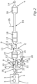
- Fig. 1 shows a schematic representation of a first embodiment of an internal combustion engine 1 designed as a reciprocating piston engine or reciprocating piston engine for a motor vehicle.
- the motor vehicle which is preferably designed as a motor vehicle, in particular as a passenger car, has the internal combustion engine 1 in its fully manufactured state and can be driven by means of the internal combustion engine 1.
- the internal combustion engine 1 has a motor housing 2 designed, for example, as a cylinder housing, in particular as a cylinder crankcase, through which combustion chambers 3 of the internal combustion engine 1 are at least partially delimited. During a fired operation of the internal combustion engine 1, combustion processes take place in the combustion chambers 3, resulting in exhaust gas from the internal combustion engine 1.
- the internal combustion engine 1 has an exhaust system 4 through which the exhaust gas can flow and also referred to as an exhaust tract. As in Fig. 1 is illustrated by an arrow 5, the exhaust gas can flow out of the combustion chambers 3, flow into the exhaust system 4 and subsequently flow through the exhaust system 4.
- the exhaust system 4 through which the exhaust gas can flow in particular the internal combustion engine 1 as a whole, has exactly two turbine wheels 6 and 7 that can be driven by the exhaust gas flowing through the exhaust system 4, the turbine wheel 6 also being referred to as the first turbine wheel and the turbine wheel 7 also being referred to as the second turbine wheel.
- the turbine wheel 6 is part of a first exhaust gas turbocharger 8
- the turbine wheel 7 is part of a second exhaust gas turbocharger 9.
- the exhaust gas turbocharger 8 includes a first compressor wheel 10 and the exhaust gas turbocharger 9 includes a second compressor wheel 11.
- the compressor wheels 10 and 11 are in one Fig. 1 Intake tract of the internal combustion engine 1, not shown and also referred to as the inlet tract, is arranged, wherein air can flow through the intake tract. By means of the intake tract, the air flowing through the intake tract is directed to and into the combustion chambers 3.
- a particularly liquid fuel is introduced into the respective combustion chamber 3, in particular injected directly.
- a fuel-air mixture also referred to simply as a mixture, is formed, which comprises the air and the fuel mentioned and is burned in the respective combustion chamber 3 during the respective combustion process.
- the internal combustion engine 1 is a diesel engine, so that the fuel is a diesel fuel.
- the respective compressor wheel 10 or 11 can be driven by the respective turbine wheel 6 or 7, in particular via a respective shaft 12 or 13 of the respective exhaust gas turbocharger 8 or 9, which in turn can be driven by the exhaust gas flowing through the exhaust system 4.
- the air flowing through the intake tract is compressed by means of the respective compressor wheel 10 or 11.
- the compressor wheel 10 is arranged downstream of the compressor wheel 11, the compressor wheels 10 and 11 being arranged or connected in series with one another, at least in an operating state of the internal combustion engine 1, that is to say arranged or connected in series. Compressing the air is also known as supercharging or supercharging. Since the compressor wheels 10 and 11 are connected in series with one another, exactly two-stage charging of the internal combustion engine 1 is provided.
- the turbine wheel 7 is arranged downstream of the turbine wheel 6 or the turbine wheel 6 is arranged upstream of the turbine wheel 7, the turbine wheels 6 and 7 being at least in the aforementioned operating state and/or at least in in a further operating state arranged or connected in series with one another, that is to say arranged or connected in series.
- This is to be understood in particular as meaning that at least part of the exhaust gas driving the turbine wheel 6 also drives the turbine wheel 7 after the part has driven the turbine wheel 6.
- the respective turbine wheel 6 or 7 can be part of a respective turbine of the respective exhaust gas turbocharger 8 or 9.
- the respective turbine can have a variable turbine geometry.
- the exhaust system 4 has exactly two SCR catalytic converters 15 and 16, the SCR catalytic converters 15 and 16 being catalytically effective exhaust gas aftertreatment elements through which the exhaust gas can flow, by means of which the exhaust gas is or can be aftertreated. Furthermore, the exhaust system 4 includes an oxidation catalytic converter 17 and a particle filter 18 as further exhaust aftertreatment elements for aftertreating the exhaust gas.
- the oxidation catalytic converter 17 is a catalytically effective or active exhaust gas aftertreatment element, since the oxidation catalytic converter - like the respective SCR catalytic converter 15 or 16 - can catalytically support and / or effect at least one respective chemical reaction, in the context of which at least a respective component of the exhaust gas reacts with at least one other substance to form a product of the reaction and is thereby removed from the exhaust gas.
- the component is nitrogen oxide contained in the exhaust gas, and with regard to the oxidation catalytic converter 17, for example, it is unburned hydrocarbons (HC) contained in the exhaust gas.
- the particle filter 18 is also designed to remove at least a component of the exhaust gas from the exhaust gas.
- the component is particles, in particular soot particles, which are or can be filtered out of the exhaust gas by means of the particle filter 18.
- the exhaust gas aftertreatment elements are therefore designed to remove at least a component of the exhaust gas from the exhaust gas.
- the oxidation catalyst 17 is, for example, a diesel oxidation catalyst (DOC), with the particle filter 18 being, for example, a diesel particle filter (DPF).
- DOC diesel oxidation catalyst
- DPF diesel particle filter
- the exhaust system 4 or the internal combustion engine 1 comprises a total of exactly four exhaust gas aftertreatment elements.
- a first of the exhaust gas aftertreatment elements is the SCR catalytic converter 15, a second of the exhaust gas aftertreatment elements is the SCR catalytic converter 16, a third of the exhaust gas aftertreatment elements is the oxidation catalytic converter 17 and the fourth exhaust gas aftertreatment element is the particle filter 18.
- the SCR -Catalyst 15 is the first SCR catalytic converter through which the exhaust gas can flow, since the second SCR catalytic converter 16 or all other, further SCR catalytic converters of the exhaust system 4 is arranged downstream of the first SCR catalytic converter 15 in the flow direction of the exhaust gas flowing through the exhaust system 4 are.
- the first SCR catalytic converter 15 is arranged between the turbine wheels 6 and 7, i.e. upstream of the turbine wheel 7 and downstream of the turbine wheel 6.
- all exhaust gas aftertreatment elements of the exhaust system 4 are arranged downstream of the second turbine wheel 7.
- the internal combustion engine 1 has a bypass line 19.
- the bypass line 19 is fluidly connected to the exhaust system 4 at a branch point A and at an introduction point E, the branch point A being arranged upstream of the SCR catalytic converter 15, in particular upstream of the turbine wheel 6, and the introduction point E is downstream of the SCR catalytic converter 15 and in particular upstream of the turbine wheel 7 and thus upstream of the other exhaust gas aftertreatment elements provided in addition to the SCR catalytic converter 15 in the form of the oxidation catalytic converter 17, the particle filter 18 and the second SCR catalytic converter 16.
- bypass line 19 By means of the bypass line 19, at least part of the exhaust gas flowing through the exhaust system 4 can be diverted from the exhaust system 4 at the branch point A and introduced into the bypass line 19.
- the exhaust gas introduced into the bypass line 19 can flow through the bypass line 19 and is guided to the introduction point E by means of the bypass line 19, bypassing the SCR catalytic converter 15, that is to say without flowing through the SCR catalytic converter 15, and into the exhaust system at the introduction point E 4 initiated.
- the bypass line 19 is part of a bypass device 20, also referred to as a bypass device, which includes the bypass line 19.
- the bypass device 20 includes a valve element 21, which is arranged, for example, in the bypass line 19.
- the turbine wheel 6 is assigned a further bypass device 22, also referred to as a wastegate or wastegate device, which comprises a further bypass line 23.
- the further bypass line 23 is fluidly connected to the exhaust system 4 at a second branch point A2 and at a second introduction point E2.
- the branch point A2 is arranged upstream of the turbine wheel 6 and preferably downstream of the branch point A, and the introduction point E2 is arranged downstream of the turbine wheel 6 and upstream of the turbine wheel 7, in particular upstream of the introduction point E and in particular upstream of the SCR catalytic converter 15.
- bypass line 23 By means of the bypass line 23, at least part of the exhaust gas flowing through the exhaust system 4 can be branched off from the exhaust system 4 at the branch point A2 and introduced into the bypass line 23.
- the exhaust gas introduced into the bypass line 23 can flow through the bypass line 23 and is thereby guided by means of the bypass line 23 from the branch point A2 to the introduction point E2 and introduced into the exhaust system 4 at the introduction point E2.
- the exhaust gas flowing through the bypass line 23 bypasses the turbine wheel 6. This means that the exhaust gas flowing through the bypass line 23 does not drive the turbine wheel 6.
- the bypass device includes 22 For example, valve element 24 arranged in the bypass line 23, by means of which a quantity of the exhaust gas flowing through the bypass line 23 and thus bypassing the turbine wheel 6 can be adjusted.
- the valve element 21 is, for example, a flap, in particular an exhaust gas control flap.
- the valve element 21 is an actuator by means of which the amount of exhaust gas flowing through the bypass line 19 can be adjusted.
- the exhaust system 4 or the internal combustion engine 1 has an in Fig. 1 particularly schematically illustrated introduction device 25, also referred to as a metering device, by means of which a reducing agent for denitrifying the exhaust gas can be introduced, in particular injected, into the exhaust gas or into the exhaust system 4 at an introduction point E3.
- the reducing agent is preferably an aqueous urea solution, which can provide ammonia.
- nitrogen oxides contained in the exhaust gas can react with the ammonia provided by the reducing agent to form water and nitrogen.
- the SCR runs, for example, in the SCR catalytic converter 15 and is catalytically effected and/or supported by the SCR catalytic converter 15.
- the introduction point E3 is arranged upstream of the SCR catalytic converter 15.
- the introduction point E3 is arranged upstream of the turbine wheel and upstream of the branch point A2, with the introduction point E3 preferably being arranged downstream of the branch point A.
- the internal combustion engine 1 or the exhaust system 4 includes a second introduction device 26, also referred to as a second metering device, by means of which the reducing agent can be introduced, in particular injected, at an introduction point E4 into the exhaust system 4 or into the exhaust gas flowing through the exhaust system 4.
- the introduction point E4 is arranged upstream of the SCR catalytic converter 16 and downstream of the SCR catalytic converter 15, in particular downstream of the turbine wheel 7.
- the introduction point E4 is arranged downstream of the oxidation catalyst 17 and downstream of the particle filter 18.
- the first turbine or the first turbine wheel 6 is used as a mixing device in order to mix the reducing agent introduced into the exhaust gas by means of the introduction device 25 at the introduction point E3 as evenly as possible with the exhaust gas.
- a separate mixing device can be avoided, in particular because the introduction point E3 is arranged upstream of the turbine wheel 6.
- the first SCR catalytic converter 15 is preferably arranged immediately after the first turbine or after the first turbine wheel 6.
- the first turbine or the first turbine wheel 6 is preferably designed to be small in order to be able to realize an advantageous response behavior.
- a temperature loss in the exhaust gas caused by the small turbine wheel 6 is small, so that the first SCR catalytic converter 15 starts quickly, that is, for example, during a warm-up phase after a cold start, it is heated particularly quickly and can therefore be brought to a sufficiently high temperature, in particular light-off temperature, particularly quickly can.
- an operating range of the SCR catalytic converter 15 is significantly increased in comparison to conventional solutions, so that the first SCR catalytic converter 15 is only bypassed via the bypass line 19 when the internal combustion engine 1 is under very high loads, also referred to as engine loads.
- the bypass line 23, in particular the bypass device 22, is preferably integrated into the first turbine, in particular into its turbine housing.
- the valve element 24 and thus the bypass line 23 are opened for a short time immediately after a cold start of the internal combustion engine 1. This eliminates enthalphic extraction by the first, small turbine wheel 6 for a short time, whereby the first SCR catalytic converter 15 can be brought to its advantageous operating temperature particularly quickly.
- a separate bypass device or bypass device, particularly external to the second turbine, is not required since a bypass device of the two-stage supercharging itself can be used.
- This also ensures that the first SCR catalytic converter 15 is bypassed via the bypass line 19 and is therefore not thermally overloaded.
- an advantageous response behavior of the first turbine and thus of the first exhaust gas turbocharger 8 can be realized since no additional thermal mass, for example in the form of a catalytic converter, is arranged upstream of the exhaust gas turbocharger 8 or the first turbine, in particular the first turbine wheel 6.
- the exhaust system 4 or the internal combustion engine 1 is free of an exhaust gas aftertreatment element arranged upstream of the SCR catalytic converter 15, in particular upstream of the turbine wheel 6, for aftertreating the exhaust gas.
- an additional, for example electrically driven or driven charging device for example to compress the air, whereby such an electrically driven charging device can optionally be dispensed with, whereby a simple structure can be realized.
- the particle filter 18 has a coating that is catalytically effective for SCR (selective catalytic reduction) and is therefore designed as a so-called SCR filter (SCRF) or as an SDPF.
- SCRF selective catalytic reduction
- the particle filter 18 is preferably completely free of a coating that is catalytically effective for the SCR, so that the particle filter 18 is preferably designed as a conventional particle filter, in particular as a conventional diesel particle filter, without a coating that is catalytically effective for the SCR.
- the particle filter 18, which is preferably designed as a diesel particle filter is arranged downstream of the oxidation catalyst 17, which is preferably designed as a diesel oxidation catalyst, which in turn is arranged downstream of the second, large turbine wheel 7.
- a major advantage of the exhaust system 4 or the internal combustion engine 1 is that the first SCR catalytic converter 15 reaches its operating temperature very quickly, without having to use excessively complex and fuel-intensive heating measures, which can be avoided or kept particularly low. This means that fuel consumption and therefore CO 2 emissions can be reduced Internal combustion engine 1 can be kept particularly low. At the same time, it can be ensured that the first SCR catalytic converter 15 or its temperature does not exceed a permissible upper temperature limit, but rather the SCR catalytic converter 15 or its temperature remains below the permissible upper temperature limit for as long as possible.
- Fig. 2 shows a schematic representation of a second embodiment of the internal combustion engine 1.
- the second embodiment differs from the first embodiment in particular in that the exhaust system 4 has a further exhaust gas aftertreatment element, presently in the form of an ammonia slip catalytic converter 27 (ASC), the ammonia slip catalytic converter 27 is another , catalytically effective exhaust gas aftertreatment element through which the exhaust gas can flow, which is designed in particular to selectively oxidize ammonia (NH 3 ), in particular to nitrogen (N 2 ) and water (H 2 O).
- the ASC is therefore catalytically effective for a reaction of ammonia, in particular with the oxygen contained in the exhaust gas, to form nitrogen and water, so that the ammonia slip catalyst 27 catalytically supports and/or effects this reaction.
- the first SCR catalytic converter 15 and the ASC are arranged in a common housing and thus form, for example, an exhaust gas aftertreatment module.
- the SCR catalyst 15 it is possible for the SCR catalyst 15 to have a first coating that is catalytically effective for the SCR, with the RSC having, for example, a second coating that is catalytically effective for the aforementioned reaction of ammonia, in particular with oxygen, to form nitrogen and water is.
- first coating and the second coating are arranged in the aforementioned common housing and/or the first coating and the second coating are arranged one after the other in the flow direction of the exhaust gas, in particular, for example, in such a way that the first coating and the second coating is spaced apart from one another in the flow direction of the exhaust gas, or that the first coating and the second coating follow one another directly or immediately in the flow direction of the exhaust gas, so that there is no other coating in the flow direction of the exhaust gas between the first coating and the second coating.
- further coating and also no area is arranged which is free of the first coating and free of the second coating.
- ammonia slip catalyst 27 is arranged upstream of the second turbine wheel 7, in particular upstream of the introduction point E, and downstream of the first turbine wheel 6, in particular downstream of the introduction point E2.
- the ammonia slip catalyst 27 or its second coating is arranged downstream of the first SCR catalyst 15 or downstream of the first coating in the flow direction of the exhaust gas flowing through the exhaust system 4.
- Fig. 3 shows a schematic representation of a third embodiment of the internal combustion engine 1.
- the third embodiment differs from the first embodiment in particular in that the exhaust system 4 has a further exhaust gas aftertreatment element in the form of an electrically heatable catalytic converter 28.
- the electrically heatable catalyst 28 is arranged downstream of the turbine wheel 6, in particular downstream of the introduction point E2 and upstream of the turbine wheel 7, in particular upstream of the introduction point E, it being provided in the present case that the catalyst 28 is arranged upstream of the first SCR catalytic converter 15.
- the electrically heatable catalyst 28 has a third coating which is catalytically effective for the SCR and/or catalytically effective for oxidation of components contained in the exhaust gas, such as CO and/or HC (unburned hydrocarbons).
- the third coating is arranged upstream of the first coating of the SCR catalytic converter 15.
- the electrically heatable catalytic converter 28, in particular its third coating, and the first SCR catalytic converter 15, in particular its first coating are arranged in a common housing and thus form an exhaust gas aftertreatment module.
- the catalyst 28 or its third coating is arranged upstream of the SCR catalyst 15 or its first coating.
- first coating and the third coating follow one another in the flow direction of the exhaust gas and are spaced apart from one another.
- first coating and the third coating follow one another in the flow direction of the exhaust gas and thereby follow one another immediately or directly.
- the electrically heatable catalytic converter 28 includes an electrically operable heating element, which is therefore also referred to as an electrical heating element.
- the electrical one Heating element can provide heat using electrical energy or electric current and thereby heat the catalytic converter 28 and/or the exhaust gas flowing through the catalytic converter 28 using the electric energy or electric current, whereby the exhaust gas or the first SCR catalytic converter 15 is heated particularly as required can be.
- FIG. 4 shows a fourth embodiment of the internal combustion engine 1.
- the fourth embodiment differs from the first embodiment in particular in that the fourth embodiment, like the third embodiment, has the electrically heatable catalytic converter 28.
- the second introduction device 26 and thus the introduction point E4 are omitted.
- the second SCR catalyst 16 is provided instead of the oxidation catalyst 17 and the particle filter 18.
- the motor vehicle has a structure designed, for example, as a self-supporting body, which delimits an engine compartment.
- the engine housing 2 is arranged in the engine compartment.
- the turbine wheels 6 and 7, in particular the exhaust gas turbochargers 8 and 11 are arranged in the engine compartment.
- the first SCR catalytic converter 15 is arranged in the engine compartment.
- the ammonia slip catalyst 27 and the electrically heatable catalyst 28, for example are also arranged in the engine compartment.
- the oxidation catalytic converter 17 and/or the particle filter 18 are also arranged in the engine compartment.
- the second SCR catalyst 16 is an underbody exhaust aftertreatment element, that is, an underbody catalyst or an underbody SCR catalyst. This means that the structure limits an interior space, also referred to as a passenger cell or passenger compartment, in which people, such as the driver of the motor vehicle, can stay during a respective journey of the motor vehicle.
- the interior is at least partially, in particular at least predominantly or completely, delimited downwards in the vertical direction of the vehicle by a floor of the structure, in particular of the self-supporting body, also referred to as the main floor.
- the SCR catalytic converter 16 is arranged outside the engine compartment and in the vertical direction of the vehicle below the floor, so that in the first, second and third embodiments the second SCR catalytic converter 16 is at least partially upwards in the vertical direction of the vehicle, in particular is at least predominantly or completely covered or overlapped by the floor.
- the second SCR catalytic converter 16 is also arranged in the engine compartment.
- the oxidation catalytic converter 17 and the particle filter 18 are designed as underbody exhaust gas aftertreatment elements and are therefore arranged outside the engine compartment and in the vertical direction of the vehicle below the floor, also referred to as the underbody, so that in the fourth embodiment the oxidation catalytic converter 17 and the Particle filter 18 in the vertical direction of the vehicle is at least partially, in particular at least predominantly and therefore at least more than half or completely, overlapped or covered by the floor, also known as the underbody.
- the exhaust gas illustrated by the arrow 5 comprises or contains a fuel catalyst originating in particular from at least one of the combustion chambers 3, which is also referred to as a fuel borne catalyst (FBC).
- the fuel catalyst is mixed with the fuel that is introduced into the respective combustion chamber 3, in particular injected directly, or the fuel catalyst contained in the exhaust gas results from an additive mixed with the fuel that is introduced into the respective combustion chamber 3.
- the fuel that is introduced into the respective combustion chamber 3 is mixed with one or the aforementioned additive, which provides or releases the fuel catalyst then contained in the exhaust gas, in particular because the mixture comprising the fuel is burned in the respective combustion chamber 3.
- the fuel catalyst is an additive added to the fuel or results from an additive added to the fuel, which is introduced with the fuel into the respective combustion chamber 3, in particular injected, and is then co-burned and deposited in soot on the particle filter 18, in particular in order to lower a burn-off temperature of the soot required to remove the soot from the particle filter 18, compared to the internal combustion engine 1 in which the FBC is not used.
Landscapes
- Engineering & Computer Science (AREA)
- Chemical & Material Sciences (AREA)
- Combustion & Propulsion (AREA)
- Mechanical Engineering (AREA)
- General Engineering & Computer Science (AREA)
- Chemical Kinetics & Catalysis (AREA)
- Health & Medical Sciences (AREA)
- Toxicology (AREA)
- Exhaust Gas After Treatment (AREA)
Claims (14)
- Moteur à combustion interne (1) pour un véhicule automobile, avec un système d'échappement (4) pouvant être traversé par les gaz d'échappement du moteur à combustion interne (1), qui présente :- une première roue de turbine (6) pouvant être entraînée par les gaz d'échappement du moteur à combustion interne (1) traversant le système d'échappement (4) ;- une deuxième roue de turbine (7) pouvant être entraînée par les gaz d'échappement, qui est agencée en aval de la première roue de turbine (6) dans la direction d'écoulement des gaz d'échappement traversant le système d'échappement (4),- plusieurs éléments de post-traitement des gaz d'échappement pouvant être traversés par les gaz d'échappement et configurés pour le post-traitement des gaz d'échappement, dont au moins un élément de post-traitement des gaz d'échappement est configuré sous la forme d'un catalyseur SCR (15), qui est le premier catalyseur SCR du système d'échappement (4) pouvant être traversé par les gaz d'échappement dans la direction d'écoulement des gaz d'échappement traversant le système d'échappement (4), le premier catalyseur SCR (15) étant agencé en amont de la deuxième roue de turbine (7) et en aval de la première roue de turbine (6) dans la direction d'écoulement des gaz d'échappement traversant le système d'échappement (4), et- au moins une conduite de contournement (19) reliée fluidiquement au système d'échappement (4) au niveau d'un point de dérivation (A) agencé en amont de la première roue de turbine (6) et au niveau d'un point d'introduction (E) agencé en aval du premier catalyseur SCR (15), au moyen de laquelle au moins une partie des gaz d'échappement traversant le système d'échappement (4) peut être dérivée du système d'échappement (4) au niveau du point de dérivation (A), être acheminée vers le point d'introduction (E) en contournant le premier catalyseur SCR (15) et être introduite dans le système d'échappement (4) au niveau du point d'introduction (E) ;caractérisé par
une deuxième conduite de dérivation (19) reliée fluidiquement au système d'échappement (4) au niveau d'un deuxième point de dérivation (A2) agencé en amont de la première roue de turbine (6) et en aval du point de dérivation (A) et au niveau d'un deuxième point d'introduction (E2) agencé en amont du premier catalyseur SCR (15) et en aval de la première roue de turbine (6), au moyen de laquelle au moins une partie des gaz d'échappement traversant le système d'échappement (4) peut être dérivée du système d'échappement (4) au niveau du deuxième point de dérivation (A2), être acheminée vers le deuxième point d'introduction (E2) en contournant la première roue de turbine (6) et être introduite dans le système d'échappement (4) au niveau du deuxième point d'introduction (E2). - Moteur à combustion interne (1) selon la revendication 1,
caractérisé en ce que
le point d'introduction (E) est agencé en amont de la deuxième roue de turbine (7). - Moteur à combustion interne (1) selon la revendication 1 ou 2,
caractérisé en ce
qu'à l'exception du premier catalyseur SCR (15), tous les éléments de post-traitement des gaz d'échappement (16, 17, 18) du système d'échappement (4) sont agencés en aval de la deuxième roue de turbine (7). - Moteur à combustion interne (1) selon l'une quelconque des revendications précédentes,
caractérisé en ce
qu'un autre des éléments de post-traitement des gaz d'échappement est configuré sous la forme d'un filtre à particules (18) agencé en aval de la deuxième roue de turbine (7). - Moteur à combustion interne (1) selon la revendication 4,
caractérisé en ce que
le filtre à particules (18) est agencé en aval du point d'introduction (E). - Moteur à combustion interne (1) selon l'une quelconque des revendications précédentes,
caractérisé en ce
qu'un autre des éléments de post-traitement des gaz d'échappement est configuré sous la forme d'un deuxième catalyseur SCR (16) agencé en aval de la deuxième roue de turbine (7). - Moteur à combustion interne (1) selon la revendication 6 lorsqu'elle se réfère à la revendication 4 ou 5,
caractérisé en ce que
le deuxième catalyseur SCR (16) est agencé en aval du filtre à particules (18). - Moteur à combustion interne (1) selon l'une quelconque des revendications précédentes,
caractérisé en ce
qu'un autre des éléments de post-traitement des gaz d'échappement est configuré sous la forme d'un catalyseur d'oxydation (17) agencé en aval de la deuxième roue de turbine (7). - Moteur à combustion interne (1) selon la revendication 8 lorsqu'elle se réfère à la revendication 6 ou 7,
caractérisé en ce que
le catalyseur d'oxydation (17) est agencé en amont du deuxième catalyseur SCR (16). - Moteur à combustion interne (1) selon l'une quelconque des revendications précédentes,
caractérisé par
au moins un dispositif de dosage (25), au moyen duquel un agent réducteur peut être chargé dans les gaz d'échappement au niveau d'un point de chargement (E3) agencé en amont du premier catalyseur SCR (15) pour dénitrifier les gaz d'échappement. - Moteur à combustion interne (1) selon l'une quelconque des revendications précédentes,
caractérisé en ce
qu'un autre des éléments de post-traitement des gaz d'échappement est configuré sous la forme d'un catalyseur de glissement d'ammoniac (27), qui est agencé en amont de la deuxième roue de turbine (7) et en aval de la première roue de turbine (6). - Moteur à combustion interne (1) selon l'une quelconque des revendications précédentes,
caractérisé en ce
qu'un autre des éléments de post-traitement des gaz d'échappement est configuré sous la forme d'un catalyseur (28) pouvant être chauffé électriquement, qui est agencé en aval de la première roue de turbine (6) et en amont de la deuxième roue de turbine (7). - Moteur à combustion interne (1) selon l'une quelconque des revendications précédentes,
caractérisé en ce que
les gaz d'échappement contiennent un catalyseur de carburant provenant d'au moins une chambre de combustion (3) du moteur à combustion interne, qui est mélangé à un carburant chargé dans la chambre de combustion (3) et prévu pour faire fonctionner le moteur à combustion interne (3) dans un mode de fonctionnement à feu du moteur à combustion interne (3) ou qui résulte d'un additif mélangé au carburant. - Véhicule automobile, avec un moteur à combustion interne (1) selon l'une quelconque des revendications précédentes.
Applications Claiming Priority (1)
| Application Number | Priority Date | Filing Date | Title |
|---|---|---|---|
| DE102021102029.8A DE102021102029A1 (de) | 2021-01-29 | 2021-01-29 | Verbrennungskraftmaschine für ein Kraftfahrzeug, insbesondere für einen Kraftwagen, sowie Kraftfahrzeug, insbesondere Kraftwagen |
Publications (2)
| Publication Number | Publication Date |
|---|---|
| EP4036386A1 EP4036386A1 (fr) | 2022-08-03 |
| EP4036386B1 true EP4036386B1 (fr) | 2023-12-20 |
Family
ID=79601679
Family Applications (1)
| Application Number | Title | Priority Date | Filing Date |
|---|---|---|---|
| EP22151298.1A Active EP4036386B1 (fr) | 2021-01-29 | 2022-01-13 | Moteur à combustion interne pour véhicule automobile, en particulier pour véhicule à moteur, ainsi que véhicule automobile, en particulier véhicule à moteur |
Country Status (2)
| Country | Link |
|---|---|
| EP (1) | EP4036386B1 (fr) |
| DE (1) | DE102021102029A1 (fr) |
Families Citing this family (1)
| Publication number | Priority date | Publication date | Assignee | Title |
|---|---|---|---|---|
| JP2024053601A (ja) * | 2022-10-04 | 2024-04-16 | 三菱重工業株式会社 | エンジンシステム、船舶 |
Family Cites Families (5)
| Publication number | Priority date | Publication date | Assignee | Title |
|---|---|---|---|---|
| EP1728989B1 (fr) * | 2005-05-31 | 2008-05-28 | BorgWarner Inc. | Arrangement des turbocompresseurs à gaz d'échappement à plusieurs étages |
| US20120216529A1 (en) | 2011-02-28 | 2012-08-30 | Cummins Intellectual Property, Inc. | Engine exhaust aftertreatment system |
| DE102011005654A1 (de) | 2011-03-16 | 2012-09-20 | Man Diesel & Turbo Se | Brennkraftmaschine |
| DE102014201579B4 (de) | 2013-02-13 | 2017-06-14 | Ford Global Technologies, Llc | Brennkraftmaschine mit selektivem Katalysator zur Reduzierung der Stickoxide und Verfahren zum Betreiben einer derartigen Brennkraftmaschine |
| DE102016202235B4 (de) | 2016-02-15 | 2021-02-04 | Ford Global Technologies, Llc | Verfahren zum Eindosieren eines Reduktionsmittels in einen Abgasstrang einer Verbrennungskraftmaschine |
-
2021
- 2021-01-29 DE DE102021102029.8A patent/DE102021102029A1/de active Pending
-
2022
- 2022-01-13 EP EP22151298.1A patent/EP4036386B1/fr active Active
Also Published As
| Publication number | Publication date |
|---|---|
| DE102021102029A1 (de) | 2022-08-04 |
| EP4036386A1 (fr) | 2022-08-03 |
Similar Documents
| Publication | Publication Date | Title |
|---|---|---|
| EP3660287B1 (fr) | Système de post-traitement des gaz d'échappement ainsi que procédé de post-traitement des gaz d'échappement d'un moteur à combustion interne | |
| DE102018107743A1 (de) | Aufwärmverfahren für Abgasbehandlungssysteme | |
| EP1405995B1 (fr) | Moteur suralimenté par un turbocompresseur à recirculation de gaz d'échappement ainsi que le procédé de fonctionnement de celui-ci | |
| EP2743470B1 (fr) | Procédé et dispositif d'élévation de la température des gaz de combustion dans la ligne d'échappement d'un moteur à combustion interne turbochargé | |
| DE102014201579A1 (de) | Brennkraftmaschine mit selektivem Katalysator zur Reduzierung der Stickoxide und Verfahren zum Betreiben einer derartigen Brennkraftmaschine | |
| EP2376749B1 (fr) | Procédé de conrôle de composants pour le post-traitement de gaz d'échappement et dispositif de post-traitement de gaz d'échappement | |
| DE102015015794A1 (de) | Verfahren zum Aufheizen einer Abgasnachbehandlungseinrichtung eines Kraftfahrzeugs, insbesondere eines Hybridfahrzeugs | |
| EP1321643B1 (fr) | Dispositif et procédé de post-traitement des gaz d'échappement | |
| DE102011100677A1 (de) | Betriebsverfahren für einen Kraftfahrzeug-Dieselmotor | |
| WO2010052055A1 (fr) | Moteur à combustion interne avec turbocompresseur et catalyseur d'oxydation | |
| DE102016212249A1 (de) | Zweistufig aufladbare direkteinspritzende Brennkraftmaschine mit Abgasnachbehandlung und Verfahren zum Betreiben einer derartigen Brennkraftmaschine | |
| EP4026994B1 (fr) | Système de post-traitement des gaz d'échappement, ainsi que procédé de post-traitement des gaz d'échappement d'un moteur à combustion interne | |
| DE102018104151A1 (de) | Abgasnachbehandlungssystem und Verfahren zur Abgasnachbehandlung eines Verbrennungsmotors | |
| DE102020100529A1 (de) | Verbrennungsmotor sowie Verfahren zum Aufheizen einer Abgasanlage eines solchen Verbrennungsmotors | |
| DE102018104275A1 (de) | Abgasnachbehandlungssystem sowie Verfahren zur Abgasnachbehandlung eines Verbrennungsmotors | |
| WO2008155268A1 (fr) | Moteur à combustion interne avec turbocompression à deux étages et catalyseur d'oxydation | |
| EP4036386B1 (fr) | Moteur à combustion interne pour véhicule automobile, en particulier pour véhicule à moteur, ainsi que véhicule automobile, en particulier véhicule à moteur | |
| DE102020103565A1 (de) | Verfahren zur Abgasnachbehandlung eines Verbrennungsmotors sowie Verbrennungsmotor | |
| DE102019123453A1 (de) | Abgasnachbehandlungssystem und Verfahren zum Temperaturmanagement eines SCR-Katalysators in der Abgasanlage eines Verbrennungsmotors | |
| DE102019006494B4 (de) | Abgasanlage für eine Verbrennungskraftmaschine eines Kraftfahrzeugs, Antriebseinrichtung für ein Kraftfahrzeug sowie Kraftfahrzeug | |
| EP3431727A1 (fr) | Moteur à combustion interne pourvu d'un turbocompresseur a gaz d'échappement | |
| DE102021117857A1 (de) | Verbrennungsmotor mit Abgasnachbehandlungssystem sowie Verfahren zur Abgasnachbehandlung eines Verbrennungsmotors | |
| EP4193044A1 (fr) | Moteur à combustion interne pour véhicule automobile, et véhicule automobile | |
| EP4074946B1 (fr) | Procédé de post-traitement des gaz d'échappement d'un moteur diesel et moteur diesel | |
| DE202013100648U1 (de) | Brennkraftmaschine mit selektivem Katalysator zur Reduzierung der Stickoxide |
Legal Events
| Date | Code | Title | Description |
|---|---|---|---|
| PUAI | Public reference made under article 153(3) epc to a published international application that has entered the european phase |
Free format text: ORIGINAL CODE: 0009012 |
|
| STAA | Information on the status of an ep patent application or granted ep patent |
Free format text: STATUS: REQUEST FOR EXAMINATION WAS MADE |
|
| 17P | Request for examination filed |
Effective date: 20220113 |
|
| AK | Designated contracting states |
Kind code of ref document: A1 Designated state(s): AL AT BE BG CH CY CZ DE DK EE ES FI FR GB GR HR HU IE IS IT LI LT LU LV MC MK MT NL NO PL PT RO RS SE SI SK SM TR |
|
| P01 | Opt-out of the competence of the unified patent court (upc) registered |
Effective date: 20230502 |
|
| GRAP | Despatch of communication of intention to grant a patent |
Free format text: ORIGINAL CODE: EPIDOSNIGR1 |
|
| STAA | Information on the status of an ep patent application or granted ep patent |
Free format text: STATUS: GRANT OF PATENT IS INTENDED |
|
| INTG | Intention to grant announced |
Effective date: 20230913 |
|
| GRAS | Grant fee paid |
Free format text: ORIGINAL CODE: EPIDOSNIGR3 |
|
| GRAA | (expected) grant |
Free format text: ORIGINAL CODE: 0009210 |
|
| STAA | Information on the status of an ep patent application or granted ep patent |
Free format text: STATUS: THE PATENT HAS BEEN GRANTED |
|
| AK | Designated contracting states |
Kind code of ref document: B1 Designated state(s): AL AT BE BG CH CY CZ DE DK EE ES FI FR GB GR HR HU IE IS IT LI LT LU LV MC MK MT NL NO PL PT RO RS SE SI SK SM TR |
|
| REG | Reference to a national code |
Ref country code: GB Ref legal event code: FG4D Free format text: NOT ENGLISH |
|
| REG | Reference to a national code |
Ref country code: DE Ref legal event code: R096 Ref document number: 502022000327 Country of ref document: DE |
|
| REG | Reference to a national code |
Ref country code: CH Ref legal event code: EP |
|
| REG | Reference to a national code |
Ref country code: IE Ref legal event code: FG4D Free format text: LANGUAGE OF EP DOCUMENT: GERMAN |
|
| PG25 | Lapsed in a contracting state [announced via postgrant information from national office to epo] |
Ref country code: GR Free format text: LAPSE BECAUSE OF FAILURE TO SUBMIT A TRANSLATION OF THE DESCRIPTION OR TO PAY THE FEE WITHIN THE PRESCRIBED TIME-LIMIT Effective date: 20240321 |
|
| REG | Reference to a national code |
Ref country code: LT Ref legal event code: MG9D |
|
| PG25 | Lapsed in a contracting state [announced via postgrant information from national office to epo] |
Ref country code: LT Free format text: LAPSE BECAUSE OF FAILURE TO SUBMIT A TRANSLATION OF THE DESCRIPTION OR TO PAY THE FEE WITHIN THE PRESCRIBED TIME-LIMIT Effective date: 20231220 |
|
| REG | Reference to a national code |
Ref country code: NL Ref legal event code: MP Effective date: 20231220 |
|
| PG25 | Lapsed in a contracting state [announced via postgrant information from national office to epo] |
Ref country code: ES Free format text: LAPSE BECAUSE OF FAILURE TO SUBMIT A TRANSLATION OF THE DESCRIPTION OR TO PAY THE FEE WITHIN THE PRESCRIBED TIME-LIMIT Effective date: 20231220 |
|
| PG25 | Lapsed in a contracting state [announced via postgrant information from national office to epo] |
Ref country code: LT Free format text: LAPSE BECAUSE OF FAILURE TO SUBMIT A TRANSLATION OF THE DESCRIPTION OR TO PAY THE FEE WITHIN THE PRESCRIBED TIME-LIMIT Effective date: 20231220 Ref country code: GR Free format text: LAPSE BECAUSE OF FAILURE TO SUBMIT A TRANSLATION OF THE DESCRIPTION OR TO PAY THE FEE WITHIN THE PRESCRIBED TIME-LIMIT Effective date: 20240321 Ref country code: FI Free format text: LAPSE BECAUSE OF FAILURE TO SUBMIT A TRANSLATION OF THE DESCRIPTION OR TO PAY THE FEE WITHIN THE PRESCRIBED TIME-LIMIT Effective date: 20231220 Ref country code: ES Free format text: LAPSE BECAUSE OF FAILURE TO SUBMIT A TRANSLATION OF THE DESCRIPTION OR TO PAY THE FEE WITHIN THE PRESCRIBED TIME-LIMIT Effective date: 20231220 Ref country code: BG Free format text: LAPSE BECAUSE OF FAILURE TO SUBMIT A TRANSLATION OF THE DESCRIPTION OR TO PAY THE FEE WITHIN THE PRESCRIBED TIME-LIMIT Effective date: 20240320 |
|
| PGFP | Annual fee paid to national office [announced via postgrant information from national office to epo] |
Ref country code: DE Payment date: 20240111 Year of fee payment: 5 |
|
| PG25 | Lapsed in a contracting state [announced via postgrant information from national office to epo] |
Ref country code: NL Free format text: LAPSE BECAUSE OF FAILURE TO SUBMIT A TRANSLATION OF THE DESCRIPTION OR TO PAY THE FEE WITHIN THE PRESCRIBED TIME-LIMIT Effective date: 20231220 |
|
| PG25 | Lapsed in a contracting state [announced via postgrant information from national office to epo] |
Ref country code: SE Free format text: LAPSE BECAUSE OF FAILURE TO SUBMIT A TRANSLATION OF THE DESCRIPTION OR TO PAY THE FEE WITHIN THE PRESCRIBED TIME-LIMIT Effective date: 20231220 Ref country code: RS Free format text: LAPSE BECAUSE OF FAILURE TO SUBMIT A TRANSLATION OF THE DESCRIPTION OR TO PAY THE FEE WITHIN THE PRESCRIBED TIME-LIMIT Effective date: 20231220 Ref country code: NO Free format text: LAPSE BECAUSE OF FAILURE TO SUBMIT A TRANSLATION OF THE DESCRIPTION OR TO PAY THE FEE WITHIN THE PRESCRIBED TIME-LIMIT Effective date: 20240320 Ref country code: NL Free format text: LAPSE BECAUSE OF FAILURE TO SUBMIT A TRANSLATION OF THE DESCRIPTION OR TO PAY THE FEE WITHIN THE PRESCRIBED TIME-LIMIT Effective date: 20231220 Ref country code: LV Free format text: LAPSE BECAUSE OF FAILURE TO SUBMIT A TRANSLATION OF THE DESCRIPTION OR TO PAY THE FEE WITHIN THE PRESCRIBED TIME-LIMIT Effective date: 20231220 Ref country code: HR Free format text: LAPSE BECAUSE OF FAILURE TO SUBMIT A TRANSLATION OF THE DESCRIPTION OR TO PAY THE FEE WITHIN THE PRESCRIBED TIME-LIMIT Effective date: 20231220 |
|
| PG25 | Lapsed in a contracting state [announced via postgrant information from national office to epo] |
Ref country code: IS Free format text: LAPSE BECAUSE OF FAILURE TO SUBMIT A TRANSLATION OF THE DESCRIPTION OR TO PAY THE FEE WITHIN THE PRESCRIBED TIME-LIMIT Effective date: 20240420 |
|
| PG25 | Lapsed in a contracting state [announced via postgrant information from national office to epo] |
Ref country code: CZ Free format text: LAPSE BECAUSE OF FAILURE TO SUBMIT A TRANSLATION OF THE DESCRIPTION OR TO PAY THE FEE WITHIN THE PRESCRIBED TIME-LIMIT Effective date: 20231220 |
|
| PG25 | Lapsed in a contracting state [announced via postgrant information from national office to epo] |
Ref country code: SK Free format text: LAPSE BECAUSE OF FAILURE TO SUBMIT A TRANSLATION OF THE DESCRIPTION OR TO PAY THE FEE WITHIN THE PRESCRIBED TIME-LIMIT Effective date: 20231220 |
|
| PG25 | Lapsed in a contracting state [announced via postgrant information from national office to epo] |
Ref country code: SM Free format text: LAPSE BECAUSE OF FAILURE TO SUBMIT A TRANSLATION OF THE DESCRIPTION OR TO PAY THE FEE WITHIN THE PRESCRIBED TIME-LIMIT Effective date: 20231220 Ref country code: SK Free format text: LAPSE BECAUSE OF FAILURE TO SUBMIT A TRANSLATION OF THE DESCRIPTION OR TO PAY THE FEE WITHIN THE PRESCRIBED TIME-LIMIT Effective date: 20231220 Ref country code: RO Free format text: LAPSE BECAUSE OF FAILURE TO SUBMIT A TRANSLATION OF THE DESCRIPTION OR TO PAY THE FEE WITHIN THE PRESCRIBED TIME-LIMIT Effective date: 20231220 Ref country code: IS Free format text: LAPSE BECAUSE OF FAILURE TO SUBMIT A TRANSLATION OF THE DESCRIPTION OR TO PAY THE FEE WITHIN THE PRESCRIBED TIME-LIMIT Effective date: 20240420 Ref country code: EE Free format text: LAPSE BECAUSE OF FAILURE TO SUBMIT A TRANSLATION OF THE DESCRIPTION OR TO PAY THE FEE WITHIN THE PRESCRIBED TIME-LIMIT Effective date: 20231220 Ref country code: CZ Free format text: LAPSE BECAUSE OF FAILURE TO SUBMIT A TRANSLATION OF THE DESCRIPTION OR TO PAY THE FEE WITHIN THE PRESCRIBED TIME-LIMIT Effective date: 20231220 |
|
| PG25 | Lapsed in a contracting state [announced via postgrant information from national office to epo] |
Ref country code: PL Free format text: LAPSE BECAUSE OF FAILURE TO SUBMIT A TRANSLATION OF THE DESCRIPTION OR TO PAY THE FEE WITHIN THE PRESCRIBED TIME-LIMIT Effective date: 20231220 Ref country code: PT Free format text: LAPSE BECAUSE OF FAILURE TO SUBMIT A TRANSLATION OF THE DESCRIPTION OR TO PAY THE FEE WITHIN THE PRESCRIBED TIME-LIMIT Effective date: 20240422 |
|
| PG25 | Lapsed in a contracting state [announced via postgrant information from national office to epo] |
Ref country code: PT Free format text: LAPSE BECAUSE OF FAILURE TO SUBMIT A TRANSLATION OF THE DESCRIPTION OR TO PAY THE FEE WITHIN THE PRESCRIBED TIME-LIMIT Effective date: 20240422 Ref country code: PL Free format text: LAPSE BECAUSE OF FAILURE TO SUBMIT A TRANSLATION OF THE DESCRIPTION OR TO PAY THE FEE WITHIN THE PRESCRIBED TIME-LIMIT Effective date: 20231220 |
|
| PG25 | Lapsed in a contracting state [announced via postgrant information from national office to epo] |
Ref country code: LU Free format text: LAPSE BECAUSE OF NON-PAYMENT OF DUE FEES Effective date: 20240113 |
|
| REG | Reference to a national code |
Ref country code: DE Ref legal event code: R097 Ref document number: 502022000327 Country of ref document: DE |
|
| PG25 | Lapsed in a contracting state [announced via postgrant information from national office to epo] |
Ref country code: LU Free format text: LAPSE BECAUSE OF NON-PAYMENT OF DUE FEES Effective date: 20240113 Ref country code: MC Free format text: LAPSE BECAUSE OF FAILURE TO SUBMIT A TRANSLATION OF THE DESCRIPTION OR TO PAY THE FEE WITHIN THE PRESCRIBED TIME-LIMIT Effective date: 20231220 |
|
| PG25 | Lapsed in a contracting state [announced via postgrant information from national office to epo] |
Ref country code: DK Free format text: LAPSE BECAUSE OF FAILURE TO SUBMIT A TRANSLATION OF THE DESCRIPTION OR TO PAY THE FEE WITHIN THE PRESCRIBED TIME-LIMIT Effective date: 20231220 |
|
| PG25 | Lapsed in a contracting state [announced via postgrant information from national office to epo] |
Ref country code: BE Free format text: LAPSE BECAUSE OF NON-PAYMENT OF DUE FEES Effective date: 20240131 |
|
| PLBE | No opposition filed within time limit |
Free format text: ORIGINAL CODE: 0009261 |
|
| STAA | Information on the status of an ep patent application or granted ep patent |
Free format text: STATUS: NO OPPOSITION FILED WITHIN TIME LIMIT |
|
| PG25 | Lapsed in a contracting state [announced via postgrant information from national office to epo] |
Ref country code: SI Free format text: LAPSE BECAUSE OF FAILURE TO SUBMIT A TRANSLATION OF THE DESCRIPTION OR TO PAY THE FEE WITHIN THE PRESCRIBED TIME-LIMIT Effective date: 20231220 |
|
| PG25 | Lapsed in a contracting state [announced via postgrant information from national office to epo] |
Ref country code: SI Free format text: LAPSE BECAUSE OF FAILURE TO SUBMIT A TRANSLATION OF THE DESCRIPTION OR TO PAY THE FEE WITHIN THE PRESCRIBED TIME-LIMIT Effective date: 20231220 Ref country code: DK Free format text: LAPSE BECAUSE OF FAILURE TO SUBMIT A TRANSLATION OF THE DESCRIPTION OR TO PAY THE FEE WITHIN THE PRESCRIBED TIME-LIMIT Effective date: 20231220 Ref country code: BE Free format text: LAPSE BECAUSE OF NON-PAYMENT OF DUE FEES Effective date: 20240131 |
|
| REG | Reference to a national code |
Ref country code: BE Ref legal event code: MM Effective date: 20240131 |
|
| 26N | No opposition filed |
Effective date: 20240923 |
|
| PG25 | Lapsed in a contracting state [announced via postgrant information from national office to epo] |
Ref country code: IE Free format text: LAPSE BECAUSE OF NON-PAYMENT OF DUE FEES Effective date: 20240113 |
|
| PG25 | Lapsed in a contracting state [announced via postgrant information from national office to epo] |
Ref country code: IE Free format text: LAPSE BECAUSE OF NON-PAYMENT OF DUE FEES Effective date: 20240113 |
|
| PG25 | Lapsed in a contracting state [announced via postgrant information from national office to epo] |
Ref country code: CY Free format text: LAPSE BECAUSE OF FAILURE TO SUBMIT A TRANSLATION OF THE DESCRIPTION OR TO PAY THE FEE WITHIN THE PRESCRIBED TIME-LIMIT; INVALID AB INITIO Effective date: 20220113 |
|
| REG | Reference to a national code |
Ref country code: CH Ref legal event code: PL |
|
| PG25 | Lapsed in a contracting state [announced via postgrant information from national office to epo] |
Ref country code: CH Free format text: LAPSE BECAUSE OF NON-PAYMENT OF DUE FEES Effective date: 20250131 |
|
| PG25 | Lapsed in a contracting state [announced via postgrant information from national office to epo] |
Ref country code: TR Free format text: LAPSE BECAUSE OF FAILURE TO SUBMIT A TRANSLATION OF THE DESCRIPTION OR TO PAY THE FEE WITHIN THE PRESCRIBED TIME-LIMIT Effective date: 20231220 |
|
| PGFP | Annual fee paid to national office [announced via postgrant information from national office to epo] |
Ref country code: GB Payment date: 20260122 Year of fee payment: 5 |
|
| PGFP | Annual fee paid to national office [announced via postgrant information from national office to epo] |
Ref country code: AT Payment date: 20260301 Year of fee payment: 5 |
|
| PGFP | Annual fee paid to national office [announced via postgrant information from national office to epo] |
Ref country code: IT Payment date: 20260130 Year of fee payment: 5 |
|
| PGFP | Annual fee paid to national office [announced via postgrant information from national office to epo] |
Ref country code: FR Payment date: 20260123 Year of fee payment: 5 |