EP4036403B1 - Fluidpumpe, steuerungssystem für eine fluidpumpe, und verfahren zum steuern einer fluidpumpe - Google Patents
Fluidpumpe, steuerungssystem für eine fluidpumpe, und verfahren zum steuern einer fluidpumpe Download PDFInfo
- Publication number
- EP4036403B1 EP4036403B1 EP21154305.3A EP21154305A EP4036403B1 EP 4036403 B1 EP4036403 B1 EP 4036403B1 EP 21154305 A EP21154305 A EP 21154305A EP 4036403 B1 EP4036403 B1 EP 4036403B1
- Authority
- EP
- European Patent Office
- Prior art keywords
- fluid pump
- sensor
- control system
- swash plate
- scanning
- Prior art date
- Legal status (The legal status is an assumption and is not a legal conclusion. Google has not performed a legal analysis and makes no representation as to the accuracy of the status listed.)
- Active
Links
Images

Classifications
-
- F—MECHANICAL ENGINEERING; LIGHTING; HEATING; WEAPONS; BLASTING
- F04—POSITIVE - DISPLACEMENT MACHINES FOR LIQUIDS; PUMPS FOR LIQUIDS OR ELASTIC FLUIDS
- F04B—POSITIVE-DISPLACEMENT MACHINES FOR LIQUIDS; PUMPS
- F04B1/00—Multi-cylinder machines or pumps characterised by number or arrangement of cylinders
- F04B1/12—Multi-cylinder machines or pumps characterised by number or arrangement of cylinders having cylinder axes coaxial with, or parallel or inclined to, main shaft axis
- F04B1/26—Control
- F04B1/30—Control of machines or pumps with rotary cylinder blocks
- F04B1/32—Control of machines or pumps with rotary cylinder blocks by varying the relative positions of a swash plate and a cylinder block
- F04B1/324—Control of machines or pumps with rotary cylinder blocks by varying the relative positions of a swash plate and a cylinder block by changing the inclination of the swash plate
-
- F—MECHANICAL ENGINEERING; LIGHTING; HEATING; WEAPONS; BLASTING
- F04—POSITIVE - DISPLACEMENT MACHINES FOR LIQUIDS; PUMPS FOR LIQUIDS OR ELASTIC FLUIDS
- F04B—POSITIVE-DISPLACEMENT MACHINES FOR LIQUIDS; PUMPS
- F04B1/00—Multi-cylinder machines or pumps characterised by number or arrangement of cylinders
- F04B1/12—Multi-cylinder machines or pumps characterised by number or arrangement of cylinders having cylinder axes coaxial with, or parallel or inclined to, main shaft axis
- F04B1/20—Multi-cylinder machines or pumps characterised by number or arrangement of cylinders having cylinder axes coaxial with, or parallel or inclined to, main shaft axis having rotary cylinder block
- F04B1/2014—Details or component parts
- F04B1/2078—Swash plates
Definitions
- Fluid pumps in particular axial piston pumps, are known and are used, for example, to convert mechanical energy into hydraulic energy. They can be used stationary or mobile. The conveying capacity can be adjusted by adjusting the swash plate.
- Known fluid pumps include a sensing system with a sensor for detecting the inclination of the swashplate to regulate, control and limit performance based on the angle. Performance control means, in particular, keeping the product of the flow rate and the assigned pressure constant. The disadvantage of such systems is that they are limited to only a few applications or that their operation is unsafe.
- the object of the invention is to provide a solution that allows the pump to be operated in a variety of different applications and thereby enables safe operation.
- the fluid pump has at least two scanning systems, each with at least one sensor for detecting the inclination of the swashplate, with at least one scanning system being part of a power limitation system.
- a first scanning system interacts with a power limitation system and a second scanning system interacts with a volume flow control system (also called delivery flow control system), a delta-p control system (also called ⁇ p control system) or a power control system.
- a volume flow control system also called delivery flow control system
- a delta-p control system also called ⁇ p control system
- At least two scanning systems are used to detect the inclination of the swashplate, with at least one scanning system being part of a power limitation system.
- Using a sensor in a power limiting system makes operation safer by preventing excessive torque.
- the power limitation can be carried out independently of the volume flow control, the delta-p control or the power control.
- the fluid pump can therefore be operated in more applications.
- At least one sensor can be arranged in a side wall of a housing to enable a compact design.
- all sensors can be arranged in one or more side walls of the housing.
- a side wall delimits the housing in a radial direction, where "radial" is to be understood in relation to a rotation axis or shaft of the drive.
- the arrangement in a side wall also has the advantage that an orientation to a transmitter element, in particular a distance from it, can be easily adjusted. This makes it easy to set the zero position or the start of the measuring range of the sensor output signal.
- the sensor can then be fixed in the appropriate orientation using a lock nut, for example.
- a first sensor of a first scanning system and a second sensor of a second scanning system can be arranged on opposite walls of a housing.
- the two sensors can be opposite each other with respect to a drive axis, rotation axis or shaft, for example a shaft that is connected to a motor of a drive.
- a drive axis, rotation axis or shaft for example a shaft that is connected to a motor of a drive.
- the drive axis, rotation axis or shaft can lie between the two sensors.
- the shaft can be coaxial with the drive axis and/or rotation axis.
- At least one scanning system is part of a power limitation system.
- the power limiting system limits the power of the fluid pump.
- the power limitation system can be designed as a pilot valve or include a pilot valve which opens depending on the pivot angle and thus controls the pressure regulator with a pilot pressure, which then regulates the pivot angle of the fluid pump by means of an actuating cylinder.
- this sensing system interacts mechanically with the rest of the power limiting system. This makes particularly safe and fast control possible, which can, for example, be independent of a power supply.
- At least one scanning system generates a mechanical output signal. This allows for simple regulation.
- At least one scanning system can be part of a volume flow control system.
- the volume flow control system can in particular adjust the inclination of the swashplate in order to regulate the amount of fluid delivered.
- the volume flow control system can interact with an actuating piston for the swash plate, or the actuating piston can be part of the volume flow control system.
- At least one scanning system can be part of a power control system or a delta-p control system.
- an output signal of a first scanning system can be mechanical and an output signal of a second scanning system can be electrical or electronic.
- the various systems allow the fluid pump to have greater operational reliability, which can in particular compensate for the failure of a system.
- the at least two scanning systems can be spatially separated from one another. They can be separate from each other. This can increase the number of possible applications.
- the fluid pump can include a pressure limiter, in particular to avoid damage caused by excessive pressure in the system. Furthermore, the fluid pump can include a pressure sensor in order to detect a pressure that is too high and/or to determine the pressure for power control and/or power limitation.
- At least one sensor is a non-contact sensor. This means that the measurement can have little impact on the operation of the fluid pump.
- at least two sensors, preferably all sensors are contactless sensors.
- a non-contact sensor can be, for example, an optical, capacitive, magnetic, magneto-resistive, inductive and/or electromagnetic sensor.
- At least one sensor is a mechanically scanning sensor.
- a mechanical sensor can be used even if the area between the sensor and the scanning surface is dirty during operation, for example because metal shavings are deposited at this point.
- the mechanical sensor can have a movable scanning head resting on the scanning surface. In such a configuration, the mechanical sensor can follow the movement of the scanning surface.
- at least two sensors, preferably all sensors, are mechanically scanning sensors.
- At least one sensor can scan a transmitter element attached to the swashplate. This can result in a particularly precise measurement.
- the transmitter element can be connected to the swashplate in an interchangeable manner without destroying it. This can make it possible to carry out particularly simple maintenance or to switch to a different measuring or scanning characteristic.
- the transmitter element can be designed as a spindle or as a rotating body.
- the transmitter element can in particular be rotationally symmetrical about an axis of a mounting section, which can have a screw thread, for example, in order to be able to dispense with alignment.
- At least one transmitter element can protrude from the swashplate on a side facing the delivery piston. This means that existing installation space can be used efficiently.
- Another sensor element can protrude from the swashplate on two sides. This can be in particular on the side of the swashplate, which is inclined towards the delivery pistons during normal operation. This makes a particularly space-saving design possible, since the space in front of the swashplate that is available on this side is also used.
- two sensors can each scan a sensor element attached to the swashplate.
- the two encoder elements can differ. They can be tailored and/or optimized to the respective intended use be.
- the scanning surfaces of the two transmitter elements can differ. For example, they can have a different inclination or a different curvature. Different curvatures can lead to different scanning characteristics. For example, a hyperbolic characteristic can be used for power control and a proportional characteristic for flow control. A distinction can be made between positive or negative identifiers. This is implemented with increasing or decreasing sampling distance.
- At least one sensor can be arranged in the half of the housing that is assigned to the drive.
- the half assigned to the drive can in particular be the half in which there is an opening for the shaft and/or where the shaft protrudes into the housing.
- a scanning system can also be used to monitor the condition of an actuating system, the delivery pistons or associated pumps.
- wear can be monitored and it can be checked whether the actuating system, the delivery piston or the associated pump should be replaced.
- the volume flow and the actual inclination of the swashplate can be measured and these values can be compared, for example, with previous values or with defined target values. If there are deviations outside of a tolerance range, the control system, the delivery pistons or the associated pump should be replaced.
- a scanning system can be part of a monitoring system that monitors wear.
- the monitoring system can also have a memory for previous measured values and/or setpoints.
- the monitoring system can, for example, have an output unit that emits a warning signal, for example acoustically, optically or via a screen.
- a warning signal for example acoustically, optically or via a screen.
- Such condition monitoring can be independent of the solution mentioned above and can also be implemented, for example, if there is only one sensor and one scanning system.
- the actuating system can include the actuating piston, a cradle and/or at least one bearing shell.
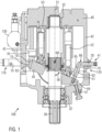
- a fluid pump 100 is shown schematically. It is an axial piston pump in which a quantity of fluid conveyed by delivery piston 52 can be changed by adjusting a swash plate 50 which can be pivoted about a pivot axis 68.
- the delivery pistons 52 are mounted in a linearly displaceable manner in a drum 53 and lie slidably against a rear side of the swash plate 50 via joints 51.
- the drum 53 is attached to a shaft 30 and rotates coaxially with it about an axis of rotation 31.
- the shaft 30 can be connected to a drive system, for example an engine of a truck. Through the fluid pump 100, the mechanical energy that is supplied with the shaft 30 can be converted into hydraulic energy.
- the angle 56 of the inclination of the swashplate 50 can be changed by an adjusting piston 55 which engages one end of the swashplate 50 and is hingedly attached to the end.
- the fluid pump 100 includes a first scanning system 110 with a first sensor 10 and a second scanning system 120 with a second sensor 20.
- the fluid pump 100 is particularly operationally reliable, as also with If one sensor 10, 20 fails, a signal can still be output from the other sensor 20, 10.
- Sensors 10, 20 that can be considered are, for example, non-contact sensors, for example optical, capacitive, magnetic, magneto-resistive, inductive and/or electromagnetic sensors.
- a mechanical sensor can also be used.
- the mechanical sensor can have a movable scanning head resting on the scanning surface 70. In such a configuration, the mechanical sensor can follow the movement of the scanning surface 70.
- the first sensing system 110 is part of a power limiting system 210 that protects the drive from excessive torque.
- the power limitation system 210 can, for example, be designed as a pilot valve or include a pilot valve that interacts with a pressure regulator 130. Furthermore, the power limitation system can be designed as an independent main stage.
- the first scanning system 110 can generate a mechanical output signal.
- the first scanning system 110 can function completely mechanically. This means it can be particularly fail-safe and can still function, for example, if the power in the system fails or electrical or magnetic interference fields occur. Furthermore, regulation can be carried out particularly quickly.
- the transmitter element 61 protrudes from the swash plate 50 on both sides, i.e. both towards the rear, on which the delivery pistons 52 lie, and towards the front.
- the transmitter element 61 can be designed as a flat body that fits into a wedge-shaped receptacle 63.
- the donor element 61 can be exchanged non-destructively.
- FIG. 2 A control system 200 for a fluid pump 100 is shown schematically.
- the control system 200 includes a power limiting system 210 that prevents damage caused by excessive power.
- the first scanning system 110 with the first sensor 10 cooperates with the power limiting system 210 or is part of the power limiting system 210.
- the power limiting system further includes a valve 212 that can divert the fluid, for example a 3/2-way valve.
- the first sensor 10 can interact directly with the valve 212.
- the sensor 10 and the first scanning system 110 can interact with a first control module 211, which in turn can control the valve 212.
- the control system 200 further comprises a volume flow control system 220.
- the second scanning system 120 with the second sensor 20 cooperates with the volume flow control system 220 or is part of the volume flow control system 220.
- the second scanning system 120 can output output signals to a second control module 221.
- the second control module 221 can then give a control signal to the valve 212 and/or a control element 222.
- the control element 222 can be the actuating piston 55 include or cooperate with this to change the inclination of the swashplate 50.
- the control element 222 can be another valve, for example a servo valve. If several valves are used, they should be connected in such a way that shutting down the fluid pump 100 always has priority.
- a scanning system 110, 120 the status of an actuating system, the delivery piston 52 or a pump (not shown) can also be monitored.
- wear can be monitored and it can be checked whether the adjusting system, comprising the adjusting piston 55, a cradle and bearing shells, the delivery pistons 52 or an associated pump should be replaced.
- the volume flow and the actual inclination of the swashplate 50 can be measured and these values can be compared, for example, with previous values or with defined target values. If there are deviations outside of a tolerance range, the adjusting piston 55, the cradle and bearing shells, or the delivery piston 52 or the pump should be replaced.
- a scanning system 110, 120 can be part of a monitoring system that monitors wear.
Landscapes
- Engineering & Computer Science (AREA)
- Mechanical Engineering (AREA)
- General Engineering & Computer Science (AREA)
- Reciprocating Pumps (AREA)
Description
- Die Erfindung betrifft eine Fluidpumpe, insbesondere eine Axialkolbenpumpe, mit wenigstens einer neigungsverstellbaren Schrägscheibe sowie ein Steuerungssystem für eine Fluidpumpe und ein Verfahren zum Steuern einer Fluidpumpe.
- Fluidpumpen, insbesondere Axialkolbenpumpen, sind bekannt und werden zum Beispiel verwendet, um mechanische Energie in hydraulische Energie umzusetzen. Sie können stationär oder mobil eingesetzt werden. Durch die Verstellung der Schrägscheibe kann die Förderleistung angepasst werden. Bekannte Fluidpumpen umfassen ein Abtastsystem mit einem Sensor zur Erfassung der Neigung der Schrägscheibe, um basierend auf dem Winkel die Leistung zu regeln, zu steuern und zu begrenzen. Leistungsregelung heißt insbesondere, das Produkt aus Förderstrom und zugeordnetem Druck konstant zu halten. Nachteilig bei solchen Systemen ist, dass sie nur auf wenige Anwendungen beschränkt sind oder der Betrieb unsicher ist.
- Aus
WO 2014/082865 A1 ist eine Axialkolbenpumpe mit einer an einer Schrägscheibe angebrachten Abtastfläche bekannt. - Aufgabe der Erfindung ist es, eine Lösung bereitzustellen, die es erlaubt, die Pumpe in einer Vielzahl von unterschiedlichen Anwendungen zu betreiben und dabei einen sicheren Betrieb ermöglicht.
- Erfindungsgemäß wird dies dadurch gelöst, dass die Fluidpumpe mindestens zwei Abtastsysteme mit jeweils mindestens einem Sensor zur Erfassung der Neigung der Schrägscheibe aufweist, wobei mindestens ein Abtastsystem Teil eines Leistungsbegrenzungssystems ist.
- Bei einem erfindungsgemäßen Steuerungssystem wirkt dabei ein erstes Abtastsystem mit einem Leistungsbegrenzungssystem und ein zweites Abtastsystem mit einem Volumenstromregelungssystem (auch Förderstromregelsystem genannt), einem delta-p-Regelsystem (auch Δp-Regelsystem genannt) oder einem Leistungsregelungssystem zusammen.
- Bei einem erfindungsgemäßen Verfahren werden mindestens zwei Abtastsysteme mit jeweils mindestens einem Sensor zur Erfassung der Neigung der Schrägscheibe verwendet, wobei mindestens ein Abtastsystem Teil eines Leistungsbegrenzungssystems ist.
- Die Verwendung eines Sensors in einem Leistungsbegrenzungssystem macht den Betrieb sicherer, da dadurch zu hohe Drehmomente verhindert werden.
- Die Leistungsbegrenzung kann dabei unabhängig von der Volumenstromregelung, der delta-p-Regelung oder der Leistungsregelung vorgenommen werden. Die Fluidpumpe kann folglich in mehr Anwendungen betrieben werden.
- Die erfindungsgemäße Lösung kann mit den folgenden, jeweils für sich vorteilhaften und beliebig miteinander kombinierbaren Weiterentwicklungen und Ausgestaltungen weiter verbessert werden.
- Mindestens ein Sensor kann in einer Seitenwand eines Gehäuses angeordnet sein, um eine kompakte Ausgestaltung zu ermöglichen. Insbesondere können alle Sensoren in einer oder mehreren Seitenwänden des Gehäuses angeordnet sein. Eine Seitenwand begrenzt das Gehäuse in einer radialen Richtung, wobei "radial" in Bezug auf eine Drehachse oder Welle des Antriebs zu verstehen ist. Die Anordnung in einer Seitenwand hat ferner den Vorteil, dass eine Ausrichtung zu einem Geberelement, insbesondere ein Abstand dazu einfach einstellbar ist. Dadurch kann auf einfache Weise die Null-Lage oder der Messbereichsbeginn des Sensorausgangssignals eingestellt werden. Der Sensor kann dann z.B. mittels einer Kontermutter in der passenden Ausrichtung fixiert werden.
- Für eine gute Trennung der beiden Sensoren können ein erster Sensor eines ersten Abtastsystems und ein zweiter Sensor eines zweiten Abtastsystems an gegenüberliegenden Wänden eines Gehäuses angeordnet sein.
- Die zwei Sensoren können sich bezüglich einer Antriebsachse, Drehachse oder Welle, beispielsweise einer Welle, die an einen Motor eines Antriebs angeschlossen ist, gegenüberliegen. Beispielsweise kann die Antriebsachse, Drehachse oder Welle zwischen den beiden Sensoren liegen. Die Welle kann koaxial mit der Antriebsachse und/oder Drehachse sein.
- Erfindungsgemäß ist mindestens ein Abtastsystem Teil eines Leistungsbegrenzungssystems. Das Leistungsbegrenzungssystem begrenzt die Leistung der Fluidpumpe. Beispielsweise kann das Leistungsbegrenzungssystem als Pilotventil ausgeführt sein oder ein Pilotventil umfassen, welches schwenkwinkelabhängig öffnet und somit den Druckregler mit einem Pilotdruck steuert, der dann den Schwenkwinkel der Fluidpumpe mittels eines Stellzylinders regelt.
- Vorzugsweise wirkt dieses Abtastsystem mechanisch mit dem Rest des Leistungsbegrenzungssystems zusammen. Dadurch ist eine besonders sichere und schnelle Regelung möglich, die beispielsweise unabhängig von einer Stromversorgung sein kann.
- In einer vorteilhaften Ausgestaltung erzeugt mindestens ein Abtastsystem ein mechanisches Ausgangssignal. Dadurch kann eine einfache Regelung erfolgen.
- Mindestens ein Abtastsystem kann Teil eines Volumenstromregelungssystems sein. Das Volumenstromregelungssystem kann insbesondere die Neigung der Schrägscheibe verstellen, um die geförderte Fluidmenge zu regeln. Das Volumenstromregelungssystem kann etwa mit einem Stellkolben für die Schrägscheibe zusammenwirken oder der Stellkolben kann Teil des Volumenstromregelungssystems sein.
- In einer alternativen oder zusätzlichen Ausgestaltung kann mindestens ein Abtastsystem ein Teil eines Leistungsregelungssystems oder eines delta-p-Regelsystems sein.
- In einer Ausgestaltung kann mindestens ein Abtastsystem ein elektrisches oder elektronisches Ausgangssignal erzeugen. Ein solches elektrisches oder elektronisches Ausgangssignal kann besonders einfach zu verarbeiten sein.
- In einer besonders vorteilhaften Ausgestaltung kann ein Ausgangssignal eines ersten Abtastsystems mechanisch, und ein Ausgangssignal eines zweiten Abtastsystems elektrisch oder elektronisch sein. Durch die verschiedenen Systeme kann die Fluidpumpe eine höhere Betriebssicherheit aufweisen, die insbesondere den Ausfall eines Systems kompensieren kann.
- Die mindestens zwei Abtastsysteme können räumlich voneinander getrennt sein. Sie können separat voneinander sein. Dadurch kann die Anzahl der möglichen Anwendungen vergrößert sein.
- Die Fluidpumpe kann einen Druckbegrenzer umfassen, insbesondere um Schäden durch einen zu hohen Druck im System zu vermeiden. Ferner kann die Fluidpumpe einen Drucksensor umfassen, um einen zu hohen Druck zu erkennen und/oder um den Druck für die Leistungsregelung und/oder Leistungsbegrenzung zu ermitteln.
- Vorzugsweise ist mindestens ein Sensor ein berührungslos arbeitender Sensor. Dadurch kann die Messung den Betrieb der Fluidpumpe wenig beeinträchtigen. In einer vorteilhaften Ausgestaltung sind mindestens zwei Sensoren, bevorzugt alle Sensoren, berührungslos arbeitende Sensoren. Ein berührungslos arbeitender Sensor kann beispielsweise ein optischer, kapazitiver, magnetischer, magneto-resistiver, induktiver und/oder elektromagnetischer Sensor sein.
- In einer weiteren vorteilhaften Ausgestaltung ist mindestens ein Sensor ein mechanisch abtastender Sensor. Dadurch kann eine Messung auch unter schwierigen Druck- und Temperaturbedingungen, wie sie im Inneren einer Fluidpumpe auftreten können, erfolgen. Auch wenn im Betrieb der Bereich zwischen dem Sensor und der Abtastfläche verschmutzt, beispielsweise weil sich an dieser Stelle Metallspäne absetzen, kann ein mechanischer Sensor verwendet werden. Der mechanische Sensor kann einen an der Abtastfläche anliegenden, beweglichen Abtastkopf aufweisen. Der mechanische Sensor kann bei einer solchen Ausgestaltung der Bewegung der Abtastfläche folgen. In einer besonders vorteilhaften Ausgestaltung sind mindestens zwei Sensoren, bevorzugt alle Sensoren, mechanisch abtastende Sensoren.
- Mindestens ein Sensor kann ein an der Schrägscheibe angebrachtes Geberelement abtasten. Dies kann eine besonders präzise Messung zur Folge haben. Das Geberelement kann ohne Zerstörung der Schrägscheibe austauschbar mit dieser verbunden sein. Dadurch kann eine besonders einfache Wartung oder besonders einfache Umstellung auf eine andere Mess- oder Abtastcharakteristik möglich sein.
- Um den Montageaufwand bei der Montage des Geberelementes zu vereinfachen und insbesondere auf eine Justierung der Ausrichtung des Geberelements verzichten zu können, kann mindestens ein Geberelement rotationssymmetrisch ausgestaltet sein.
- Das Geberelement kann spindelförmig oder als Rotationskörper ausgestaltet sein. Das Geberelement kann insbesondere rotationssymmetrisch um eine Achse eines Montageabschnitts, der beispielsweise ein Schraubengewinde aufweisen kann, sein, um auf eine Ausrichtung verzichten zu können.
- In der besonders platzsparenden Ausgestaltung kann mindestens ein Geberelement an einer den Förderkolben zugewandten Seite von der Schrägscheibe abstehen. Bereits vorhandener Bauraum kann dadurch effizient genutzt werden.
- Ein weiteres Geberelement kann an zwei Seiten von der Schrägscheibe vorstehen. Dies kann insbesondere auf der Seite der Schrägscheibe sein, die im normalen Betrieb zu den Förderkolben hin geneigt ist. Dadurch kann eine besonders platzsparende Ausgestaltung möglich sein, da auch Platz vor der Schrägscheibe genutzt wird, der auf dieser Seite vorhanden ist.
- Für eine erhöhte Betriebssicherheit können zwei Sensoren jeweils ein an der Schrägscheibe angebrachtes Geberelement abtasten. Dabei können sich die zwei Geberelemente unterscheiden. Sie können auf den jeweiligen Verwendungszweck abgestimmt und/oder optimiert sein. Insbesondere können sich die Abtastflächen der zwei Geberelemente unterscheiden. Sie können beispielsweise eine unterschiedliche Neigung oder eine unterschiedliche Krümmung aufweisen. Unterschiedliche Krümmungen können zu verschiedenen Abtastcharakteristiken führen. Zum Beispiel kann eine hyperbolische Kennlinie für die Leistungsregelung und eine proportionale Kennlinie für die Förderstromregelung verwendet werden. Dabei kann zwischen positiver oder negativer Kennung unterschieden werden. Dies wird mit zunehmendem oder abnehmenden Abtastabstand umgesetzt.
- In einer vorteilhaften Ausgestaltung kann mindestens ein Sensor in der vorderen Hälfte des Gehäuses angeordnet sein. Insbesondere können alle Sensoren in der vorderen Hälfte des Gehäuses angeordnet sein. Als vordere Hälfte ist die Hälfte zu verstehen, mit der die Fluidpumpe an einem Antriebsmotor oder einem Getriebegehäuse angebaut wird. Dadurch kann die Gewichtsverteilung verbessert sein, was die Getriebewandbelastung reduziert bzw. den Anbau der Fluidpumpe ohne zusätzliche Abstützung am Fahrzeugrahmen ermöglicht.
- Ebenfalls zur Erzielung einer vorteilhaften Gewichtsverteilung kann mindestens ein Sensor in der Hälfte des Gehäuses angeordnet sein, die dem Antrieb zugeordnet ist. Die dem Antrieb zugeordnete Hälfte kann insbesondere die Hälfte sein, in der eine Öffnung für die Welle ist und/oder an der die Welle in das Gehäuse ragt.
- Mithilfe eines Abtastsystems kann auch eine Zustandsüberwachung eines Stellsystems, der Förderkolben oder dazugehöriger Pumpen erfolgen. Insbesondere kann ein Verschleiß überwacht werden und geprüft werden, ob das Stellsystem, die Förderkolben oder die zugehörige Pumpe ausgetauscht werden sollte. Dazu können der Volumenstrom und die tatsächliche Neigung der Schrägscheibe gemessen werden und diese Werte z.B. mit früheren Werten oder mit definierten Sollwerten verglichen werden. Ergeben sich Abweichungen außerhalb eines Toleranzbereichs, so sollten das Stellsystem, die Förderkolben oder die zugehörige Pumpe ausgetauscht werden. Ein Abtastsystem kann Teil eines Überwachungssystems sein, das einen Verschleiß überwacht. Das Überwachungssystem kann ferner einen Speicher für frühere Messwerte und/oder Sollwerte aufweisen. Ferner kann das Überwachungssystem z.B. eine Ausgabeeinheit aufweisen, die ein Warnsignal ausgibt, z.B. akustisch, optisch oder über einen Bildschirm. Eine solche Zustandsüberwachung kann unabhängig von der oben genannten Lösung sein und z.B. auch implementiert werden, wenn nur ein Sensor und ein Abtastsystem vorhanden ist. Das Stellsystem kann den Stellkolben, eine Wiege und/oder mindestens eine Lagerschale umfassen.
- Im Folgenden wird die Erfindung anhand vorteilhafter Ausgestaltungen mit Bezug auf die Zeichnungen beispielhaft näher erläutert. Die dabei dargestellten vorteilhaften Weiterentwicklungen und Ausgestaltungen sind jeweils voneinander unabhängig und können beliebig miteinander kombiniert werden, je nachdem, wie dies im Anwendungsfall notwendig ist.
- Es zeigen:
- Fig. 1
- eine schematische Querschnittsdarstellung einer Ausführungsform einer Fluidpumpe;
- Fig. 2
- eine schematische Darstellung eines Ausführungsbeispiels eines Steuerungssystems für eine Fluidpumpe.
- In
Fig. 1 ist eine Fluidpumpe 100 schematisch dargestellt. Es handelt sich um eine Axialkolbenpumpe, bei der eine durch Förderkolben 52 geförderte Menge des Fluides durch Verstellen einer um eine Schwenkachse 68 verschwenkbaren Schrägscheibe 50 verändert werden kann. Die Förderkolben 52 sind in einer Trommel 53 linearverschieblich gelagert und liegen über Gelenke 51 gleitend an einer Rückseite der Schrägscheibe 50 an. - Die Trommel 53 ist an einer Welle 30 angebracht und rotiert zusammen mit dieser koaxial um eine Drehachse 31. Die Welle 30 kann mit einem Antriebssystem, beispielsweise einem Motor eines LKWs, verbunden sein. Durch die Fluidpumpe 100 kann die mechanische Energie, die mit der Welle 30 zugeführt wird, in hydraulische Energie umgewandelt werden.
- Der Winkel 56 der Neigung der Schrägscheibe 50 kann durch einen Stellkolben 55 verändert werden, der an einem Ende der Schrägscheibe 50 angreift und an dem Ende gelenkig angebracht ist.
- Zur Erfassung der Neigung der Schrägscheibe 50 umfasst die Fluidpumpe 100 ein erstes Abtastsystem 110 mit einem ersten Sensor 10 und ein zweites Abtastsystem 120 mit einem zweiten Sensor 20. Durch die Verwendung von zwei Sensoren 10, 20 ist die Fluidpumpe 100 besonders betriebssicher, da auch bei einem Ausfall eines Sensors 10, 20 immer noch ein Signal von dem anderen Sensor 20, 10 ausgegeben werden kann.
- Die Abtastsysteme 110, 120 sind separat und räumlich voneinander getrennt. Die Sensoren 10, 20 sind jeweils in einer Seitenwand 42 eines Gehäuses 40 der Fluidpumpe 100 angeordnet. Die Seitenwand 42 verläuft im Wesentlichen parallel zur Drehachse 31 und begrenzt das Gehäuse 40 in einer radialen Richtung. Die Anordnung in der Seitenwand 42 erleichtert die Justierung der Sensoren 10, 20, da eine Ausrichtung zu einem Geberelement 61, 62 und damit die Einstellung der Null-Lage oder des Messbereichsbeginns des Sensorausgangssignals einfach ist. Der Sensor 10, 20 kann dann z.B. mittels einer Kontermutter in der passenden Ausrichtung, insbesondere bei dem richtigen Abtastabstand 66, fixiert werden.
- Die Sensoren 10, 20 liegen sich bezüglich der Welle 30 bzw. der Drehachse 31 gegenüber, liegen also an gegenüberliegenden Wänden des Gehäuses 40.
- Als Sensoren 10, 20 kommen beispielsweise berührungslos arbeitende Sensoren, beispielsweise optische, kapazitive, magnetische, magneto-resistive, induktive und/oder elektromagnetische Sensoren in Betracht. Falls jedoch im Betrieb der Bereich zwischen dem Sensor 10, 20 und einer Abtastfläche 70 verschmutzt, beispielsweise weil sich an dieser Stelle Metallspäne absetzen, kann auch ein mechanischer Sensor verwendet werden. Der mechanische Sensor kann einen an der Abtastfläche 70 anliegenden, beweglichen Abtastkopf aufweisen. Der mechanische Sensor kann bei einer solchen Ausgestaltung der Bewegung der Abtastfläche 70 folgen. Das erste Abtastsystem 110 ist Teil eines Leistungsbegrenzungssystems 210, das den Antrieb vor einem zu hohen Drehmoment schützt. Das Leistungsbegrenzungssystem 210 kann zum Beispiel als Pilot-Ventil ausgestaltet sein oder ein Pilot-Ventil umfassen, das mit einem Druckregler 130 zusammenwirkt. Ferner kann das Leistungsbegrenzungssystem als eigenständige Hauptstufe ausgebildet sein.
- Für eine besonders große Betriebssicherheit kann das erste Abtastsystem 110 ein mechanisches Ausgangssignal erzeugen. Insbesondere kann das erste Abtastsystem 110 komplett mechanisch funktionieren. Dadurch kann es besonders ausfallsicher sein und zum Beispiel immer noch funktionieren, wenn der Strom im System ausfällt oder elektrische oder magnetische Störfelder auftreten. Ferner kann eine Regelung dadurch besonders schnell erfolgen.
- Das erste Abtastsystem 110 tastet ein erstes Geberelement 61 ab, das in einer Aufnahme 63 der Schrägscheibe 50 angebracht ist. Der Abstand zwischen der außenliegenden Abtastfläche 70 und beispielsweise einem Grundkörper oder Gehäuse des Sensors 10 bzw. der Seitenwand 42 lässt Rückschlüsse auf den Neigungswinkel 56 der Schrägscheibe 50 zu. Der Sensor 10 kann die Abtastfläche 70 zum Beispiel mechanisch abtasten.
- Das Geberelement 61 ist austauschbar, wodurch verschiedene Abtast- oder Messcharakteristiken realisiert werden können. Dies kann etwa durch verschiedene Verläufe der Abtastfläche 70 erzielt werden, insbesondere durch verschiedene Krümmungen. So kann z.B eine hyperbolische Kennlinie für eine Leistungsregelung und eine proportionale Kennlinie für eine Förderstromregelung verwendet werden. Dabei kann zwischen positiver oder negativer Kennung unterschieden werden. Dies wird mit zunehmendem oder abnehmenden Abtastabstand 66 umgesetzt. Ferner kann durch geeignete Wahl der Abtastfläche 70 der Messbereich insgesamt abgegrenzt werden.
- Das Geberelement 61 ragt beidseits von der Schrägscheibe 50 vor, d.h. sowohl in Richtung der Rückseite, an der die Förderkolben 52 liegen, als auch in Richtung zur Vorderseite.
- Das Geberelement 61 kann als Flachkörper ausgestaltet sein, der in eine keilförmige Aufnahme 63 passt. Das Geberelement 61 kann zerstörungsfrei austauschbar sein.
- Der zweite Sensor 20 des zweiten Abtastsystems 120 wirkt ebenfalls mit einem Geberelement 62 zusammen. Das Geberelement 62 ragt jedoch nur von der Rückseite der Schrägscheibe 50 hervor. Dies ist besonders platzsparend, da dann an der Vorderseite kein Extraplatz notwendig ist, und die Schrägscheibe 50 bis zu einem minimalen Winkel, der durch einen Anschlag 57 einstellbar ist, verschwenkt werden kann. Der in dem Beispiel gezeigte Winkel 56 ist in diesem Fall maximal 90°, was keiner Förderung entspricht.
- Der Sensor 20 tastet wieder eine Abtastfläche 70 an dem Geberelement 62 ab. Aus dem Abtastabstand 66 zwischen dem Sensor 20, beispielsweise dem Sensorgehäuse, und der Abtastfläche 70 kann wieder auf den Winkel 56 der Schrägscheibe 50 geschlossen werden. Auch hier ist es durch die Austauschbarkeit des Geberelements 62 möglich, verschiedene Messcharakteristiken zu benutzen.
- Das Geberelement 62 ist an einem Montageabschnitt 64 mit der Schrägscheibe 50 verbunden. In dem Montageabschnitt 64 kann beispielsweise ein Schraubengewinde vorhanden sein, dass mit einem entsprechenden Schraubengewinde an der Schrägscheibe 50 zusammenwirkt. Das Geberelement 62 kann also durch Rotation mit der Schrägscheibe verbunden werden. Um eine Justierung der Abtastfläche 70 unnötig zu machen, kann das Geberelement 62 rotationssymmetrisch um eine Montageachse 65 sein, um die das Geberelement 62 bei der Montage rotiert. Das Geberelement 62 ist folglich spindelförmig oder bildet einen Rotationskörper.
- Das zweite Abtastsystem 120 kann mit einem Leistungsregelungssystem, delta-p-Regelsystem oder wie gezeigt mit einem Volumenstromregelungssystem 220 zusammenwirken und/oder Teil eines Leistungsregelungssystems, delta-p-Regelsystems oder Volumenstromregelungssystems 220 sein. Insbesondere kann das Leistungsregelungssystem oder Volumenstromregelungssystem 220 die Neigung der Schrägscheibe 50 beeinflussen und dadurch die Leistung oder den Förderstrom (oder auch das Volumen) der Fluidpumpe 100 regeln.
- Der Sensor 20 des zweiten Abtastsystems 120 kann berührungslos arbeiten, um die Bewegung der Schrägscheibe 50 nicht weiter zu beeinflussen. Beispielsweise kann der Sensor 20 eine Abstandsmessung induktiv oder kapazitiv durchführen. Das zweite Abtastsystem 120 kann ein elektrisches oder elektronisches Ausgangssignal erzeugen, das dann weiterverarbeitet werden kann.
- Die zwei Sensoren 10, 20 sind in einer vorderen Hälfte 41 des Gehäuses 40 angeordnet. Die vordere Hälfte ist die Hälfte, die mit dem Antriebsgetriebe verbunden ist. Dadurch ist die Gewichtsverteilung verbessert. Die vordere Hälfte 41 ist in diesem Fall die Hälfte, in der die Welle 30 in das Gehäuse 40 eintritt.
- Die Fluidpumpe 100 kann einen Druckbegrenzer umfassen, der Teil des Leistungsbegrenzungssystems 210 sein kann und beispielsweise Teil des Druckreglers 130 sein kann. Ferner kann die Fluidpumpe einen Drucksensor aufweisen, der beispielsweise im Druckregler 130 angebracht sein kann.
- In
Fig. 2 ist schematisch ein Steuerungssystem 200 für eine Fluidpumpe 100 dargestellt. - Das Steuerungssystem 200 umfasst ein Leistungsbegrenzungssystem 210, das Schäden durch zu hohe Leistung verhindert. Das erste Abtastsystem 110 mit dem ersten Sensor 10 wirkt mit dem Leistungsbegrenzungssystem 210 zusammen bzw. ist ein Teil des Leistungsbegrenzungssystems 210. Das Leistungsbegrenzungssystem umfasst ferner ein Ventil 212, das das Fluid umleiten kann, beispielsweise ein 3/2-Wege-Ventil. Der erste Sensor 10 kann direkt mit dem Ventil 212 zusammenwirken. Ferner können der Sensor 10 und das erste Abtastsystem 110 mit einem ersten Steuerungsmodul 211 zusammenwirken, das wiederum das Ventil 212 steuern kann.
- Das Steuerungssystem 200 umfasst ferner ein Volumenstromregelungssystem 220. Das zweite Abtastsystem 120 mit dem zweiten Sensor 20 wirkt mit dem Volumenstromregelungssystem 220 zusammen bzw. ist ein Teil des Volumenstromregelungssystem 220. Das zweite Abtastsystem 120 kann Ausgangssignale an ein zweites Steuerungsmodul 221 abgeben. Das zweite Steuerungsmodul 221 kann dann ein Steuersignal an das Ventil 212 und/oder ein Steuerungselement 222 geben. Beispielsweise kann das Steuerungselement 222 den Stellkolben 55 umfassen oder mit diesem zusammenwirken, um die Neigung der Schrägscheibe 50 zu verändern. Das Steuerungselement 222 kann etwa ein weiteres Ventil sein, beispielsweise ein Servoventil. Wenn mehrere Ventile verwendet werden, sollten diese so verschaltet sein, dass das Abregeln der Fluidpumpe 100 immer Vorrang hat.
- Das erste Steuerungsmodul 211 und das zweite Steuerungsmodul 221 können jeweils mit einem zentralen Steuerungsmodul 230 zusammenwirken und beispielsweise Ausgangssignale an das zentrale Steuerungsmodul 230 geben oder Eingangssignale von dem Steuerungsmodule 230 empfangen. Das zentrale Steuerungsmodul 230 kann beispielsweise in ein Steuerungssystem des LKWs integriert sein oder mit diesem zusammenwirken.
- Mithilfe eines Abtastsystems 110, 120 kann auch eine Zustandsüberwachung eines Stellsystems, der Förderkolben 52 oder einer Pumpe (nicht gezeigt) dafür erfolgen. Insbesondere kann ein Verschleiß überwacht werden und geprüft werden, ob das Stellsystem, umfassend den Stellkolben 55, eine Wiege und Lagerschalen, die Förderkolben 52 oder eine dazugehörige Pumpe ausgetauscht werden sollte. Dazu können der Volumenstrom und die tatsächliche Neigung der Schrägscheibe 50 gemessen werden und diese Werte z.B. mit früheren Werten oder mit definierten Sollwerten verglichen werden. Ergeben sich Abweichungen außerhalb eines Toleranzbereichs, so sollten der Stellkolben 55, die Wiege und Lagerschalen, bzw. die Förderkolben 52 oder die Pumpe ausgetauscht werden. Ein Abtastsystem 110, 120 kann Teil eines Überwachungssystems sein, das einen Verschleiß überwacht. Das Überwachungssystem kann ferner einen Speicher für frühere Messwerte und/oder Sollwerte aufweisen. Ferner kann das Überwachungssystem z.B. eine Ausgabeeinheit aufweisen, die ein Warnsignal ausgibt, z.B. akustisch, optisch oder über einen Bildschirm. Eine solche Zustandsüberwachung kann unabhängig von der oben genannten Lösung sein und z.B. auch implementiert werden, wenn nur ein einziger Sensor 10, 20 und ein einziges Abtastsystem 110, 120 vorhanden ist. Ein Überwachungssystem kann zumindest teilweise in das zentrale Steuermodul 230 integriert sein oder das zentrale Steuermodul 230 umfassen.
-
- 10
- erster Sensor
- 20
- zweiter Sensor
- 30
- Welle
- 31
- Drehachse
- 32
- Lager
- 40
- Gehäuse
- 41
- vordere Hälfte
- 42
- Seitenwand
- 50
- Schrägscheibe
- 51
- Gelenk
- 52
- Förderkolben
- 53
- Trommel
- 55
- Stellkolben
- 56
- Winkel
- 57
- Anschlag
- 61
- Geberelement
- 62
- Geberelement
- 63
- Aufnahme
- 64
- Montageabschnitt
- 65
- Montageachse
- 66
- Abtastabstand
- 68
- Schwenkachse
- 70
- Abtastfläche
- 100
- Fluidpumpe
- 110
- erstes Abtastsystem
- 120
- zweites Abtastsystem
- 130
- Druckregler
- 200
- Steuerungssystem
- 210
- Leistungsbegrenzungssystem
- 211
- erstes Steuerungsmodul
- 212
- Ventil
- 220
- Volumenstromregelungssystem
- 221
- zweites Steuerungsmodul
- 222
- Steuerungselement
- 230
- zentrales Steuerungsmodul
Claims (14)
- Fluidpumpe (100), insbesondere eine Axialkolbenpumpe, mit wenigstens einer neigungsverstellbaren Schrägscheibe (50), dadurch gekennzeichnet, dass die Fluidpumpe (100) mindestens zwei Abtastsysteme (110, 120) mit jeweils mindestens einem Sensor (10, 20) zur Erfassung der Neigung der Schrägscheibe (50) aufweist, wobei mindestens ein Abtastsystem (110) Teil eines Leistungsbegrenzungssystems (210) ist.
- Fluidpumpe (100) nach Anspruch 1, wobei mindestens ein Sensor (10, 20) in einer Seitenwand (42) eines Gehäuses (40) angeordnet ist.
- Fluidpumpe (100) nach Anspruch 1 oder 2, wobei ein erster Sensor (10) eines ersten Abtastsystems (110) und ein zweiter Sensor (20) eines zweiten Abtastsystems (120) an gegenüberliegenden Wänden eines Gehäuses (40) angeordnet sind.
- Fluidpumpe (100) nach einem der Ansprüche 1 bis 3, wobei sich die zwei Sensoren (10, 20) bezüglich einer Welle (30) gegenüberliegen.
- Fluidpumpe (100) nach einem der Ansprüche 1 bis 4, wobei mindestens ein Abtastsystem (110) ein mechanisches Ausgangssignal erzeugt.
- Fluidpumpe (100) nach einem der Ansprüche 1 bis 5, wobei mindestens ein Abtastsystem (120) Teil eines Volumenstromregelungssystems (220), eines Leistungsregelungssystems oder eines delta-p-Regelsystems ist.
- Fluidpumpe (100) nach einem der Ansprüche 1 bis 6, wobei mindestens ein Abtastsystem (120) ein elektrisches oder elektronisches Ausgangssignal erzeugt.
- Fluidpumpe (100) nach einem der Ansprüche 1 bis 7, wobei mindestens ein Sensor (10, 20) ein an der Schrägscheibe (50) angebrachtes Geberelement (61, 62) abtastet.
- Fluidpumpe (100) nach einem der Ansprüche 1 bis 8, wobei mindestens ein Geberelement (62) rotationsymmetrisch ausgestaltet ist.
- Fluidpumpe (100) nach einem der Ansprüche 1 bis 9, wobei mindestens ein Geberelement (62) an einer dem Förderkolben (52) zugewandten Seite von der Schrägscheibe (50) absteht.
- Fluidpumpe (100) nach einem der Ansprüche 1 bis 10, wobei mindestens ein Sensor (10, 20) in der vorderen Hälfte (41) des Gehäuses (40) angeordnet ist.
- Steuerungssystem (200) für eine Fluidpumpe (100), insbesondere eine Axialkolbenpumpe, die wenigstens eine neigungsverstellbare Schrägscheibe (50) aufweist, dadurch gekennzeichnet, dass das Steuerungssystem (200) mindestens zwei Abtastsysteme (110, 120) mit jeweils mindestens einem Sensor (10, 20) zur Erfassung der Neigung der Schrägscheibe (50), ein Leistungsbegrenzungssystem (210) und ein Volumenstromregelungssystem (220), ein Leistungsregelungssystem oder ein delta-p-Regelsystem umfasst, wobei ein erstes Abtastsystem (110) mit dem Leistungsbegrenzungssystem (210) zusammenwirkt und ein zweites Abtastsystem (120) mit dem Volumenstromregelungssystem (220), dem Leistungsregelungssystem bzw. dem delta-p-Regelsystem zusammenwirkt.
- Steuerungssystem (200) nach Anspruch 12, wobei das Steuerungssystem (200) eine Fluidpumpe (100) nach einem der Ansprüche 1 bis 11 umfasst.
- Verfahren zum Steuern einer Fluidpumpe (100), insbesondere einer Axialkolbenpumpe, mit wenigstens einer neigungsverstellbaren Schrägscheibe (50), dadurch gekennzeichnet, dass mindestens zwei Abtastsysteme (110, 120) mit jeweils mindestens einem Sensor (10, 20) zur Erfassung der Neigung der Schrägscheibe (50) verwendet werden, wobei mindestens ein Abtastsystem (110) Teil eines Leistungsbegrenzungssystems (210) ist.
Priority Applications (1)
| Application Number | Priority Date | Filing Date | Title |
|---|---|---|---|
| EP21154305.3A EP4036403B1 (de) | 2021-01-29 | 2021-01-29 | Fluidpumpe, steuerungssystem für eine fluidpumpe, und verfahren zum steuern einer fluidpumpe |
Applications Claiming Priority (1)
| Application Number | Priority Date | Filing Date | Title |
|---|---|---|---|
| EP21154305.3A EP4036403B1 (de) | 2021-01-29 | 2021-01-29 | Fluidpumpe, steuerungssystem für eine fluidpumpe, und verfahren zum steuern einer fluidpumpe |
Publications (2)
| Publication Number | Publication Date |
|---|---|
| EP4036403A1 EP4036403A1 (de) | 2022-08-03 |
| EP4036403B1 true EP4036403B1 (de) | 2023-12-27 |
Family
ID=74418275
Family Applications (1)
| Application Number | Title | Priority Date | Filing Date |
|---|---|---|---|
| EP21154305.3A Active EP4036403B1 (de) | 2021-01-29 | 2021-01-29 | Fluidpumpe, steuerungssystem für eine fluidpumpe, und verfahren zum steuern einer fluidpumpe |
Country Status (1)
| Country | Link |
|---|---|
| EP (1) | EP4036403B1 (de) |
Family Cites Families (3)
| Publication number | Priority date | Publication date | Assignee | Title |
|---|---|---|---|---|
| US5554007A (en) * | 1994-10-17 | 1996-09-10 | Caterpillar Inc. | Variable displacement axial piston hydraulic unit |
| DE102012221922A1 (de) * | 2012-11-29 | 2014-06-05 | Hawe Inline Hydraulik Gmbh | Pumpe, insbesondere Axialkolbenpumpe mit Abtastfläche an der Schrägscheibe |
| CN111779663B (zh) * | 2020-06-28 | 2021-04-20 | 浙江大学 | 一种斜盘式变量轴向柱塞泵的变量控制特性工况模拟实时检测系统及方法 |
-
2021
- 2021-01-29 EP EP21154305.3A patent/EP4036403B1/de active Active
Also Published As
| Publication number | Publication date |
|---|---|
| EP4036403A1 (de) | 2022-08-03 |
Similar Documents
| Publication | Publication Date | Title |
|---|---|---|
| DE3843924C2 (de) | ||
| DE69706700T2 (de) | Steuersystem für eine luftschraube mit gegengewicht | |
| EP3466806B1 (de) | Verstellpropeller-einheit mit einer hydraulischen steuervorrichtung | |
| EP2883788B1 (de) | Propellereinheit mit Regler | |
| EP2504578B2 (de) | Schraubenspindelpumpe mit integriertem druckbegrenzungsventil | |
| EP0914888B1 (de) | Stranggiesskokille | |
| DE102012021320A1 (de) | Verstellvorrichtung für eine hydrostatische Kolbenmaschine und hydrostatische Kolbenmaschine mit einer derartigen Verstellvorrichtung | |
| EP0305761B1 (de) | Sekundärgeregeltes hydrostatisches Getriebe mit offenem Kreislauf | |
| DE69706905T2 (de) | Verstellbare Pumpe sowie Fernsteuersystem dafür | |
| EP4036403B1 (de) | Fluidpumpe, steuerungssystem für eine fluidpumpe, und verfahren zum steuern einer fluidpumpe | |
| EP4190689A1 (de) | Propelleranordnung mit pumpeneinheit | |
| DE4405234C1 (de) | Vorrichtung zur Summenleistungsregelung von wenigstens zwei hydrostatischen Verstellpumpen | |
| DE102020109134A1 (de) | Axialkolbenmaschine | |
| EP2302242B1 (de) | Verfahren und Vorrichtung zur Konditionierung von Lagersystemen für Wellen | |
| DE29805351U1 (de) | Lageranordnung | |
| DE10058757A1 (de) | Galette | |
| DE19855899A1 (de) | Axialkolbenmaschine | |
| EP2336566B1 (de) | Wälzlageranordnung | |
| DE10347085B3 (de) | Hydrostatische Kolbenmaschine mit zwei hydraulischen Kreisläufen | |
| DE3244615C2 (de) | ||
| DE102015205549B4 (de) | Verfahren zur kalibrierung einer hydraulikmaschine und hydraulikmaschine mit verstellelement | |
| DE2943994B1 (de) | Hydraulsiche Hubvorrichtung fuer Arbeitsgeraete,insbesondere an Schleppern | |
| AT511129B1 (de) | Anordnung, Refiner und Verfahren | |
| EP0042368A1 (de) | Einrichtung zur Verstellung des Förderbeginnes einer Brennstoffeinspritzpumpe für Brennkraftmaschinen | |
| DE10108006A1 (de) | Verfahren zur Überwachung einer Hubkolbenmaschine sowie diesbezügliche Hubkolbenmaschine |
Legal Events
| Date | Code | Title | Description |
|---|---|---|---|
| PUAI | Public reference made under article 153(3) epc to a published international application that has entered the european phase |
Free format text: ORIGINAL CODE: 0009012 |
|
| STAA | Information on the status of an ep patent application or granted ep patent |
Free format text: STATUS: THE APPLICATION HAS BEEN PUBLISHED |
|
| AK | Designated contracting states |
Kind code of ref document: A1 Designated state(s): AL AT BE BG CH CY CZ DE DK EE ES FI FR GB GR HR HU IE IS IT LI LT LU LV MC MK MT NL NO PL PT RO RS SE SI SK SM TR |
|
| STAA | Information on the status of an ep patent application or granted ep patent |
Free format text: STATUS: REQUEST FOR EXAMINATION WAS MADE |
|
| 17P | Request for examination filed |
Effective date: 20230202 |
|
| RBV | Designated contracting states (corrected) |
Designated state(s): AL AT BE BG CH CY CZ DE DK EE ES FI FR GB GR HR HU IE IS IT LI LT LU LV MC MK MT NL NO PL PT RO RS SE SI SK SM TR |
|
| GRAP | Despatch of communication of intention to grant a patent |
Free format text: ORIGINAL CODE: EPIDOSNIGR1 |
|
| STAA | Information on the status of an ep patent application or granted ep patent |
Free format text: STATUS: GRANT OF PATENT IS INTENDED |
|
| RIC1 | Information provided on ipc code assigned before grant |
Ipc: F04B 1/324 20200101ALI20230704BHEP Ipc: F04B 1/2078 20200101AFI20230704BHEP |
|
| INTG | Intention to grant announced |
Effective date: 20230803 |
|
| GRAS | Grant fee paid |
Free format text: ORIGINAL CODE: EPIDOSNIGR3 |
|
| RAP3 | Party data changed (applicant data changed or rights of an application transferred) |
Owner name: INLINE HYDRAULIK GMBH |
|
| GRAA | (expected) grant |
Free format text: ORIGINAL CODE: 0009210 |
|
| STAA | Information on the status of an ep patent application or granted ep patent |
Free format text: STATUS: THE PATENT HAS BEEN GRANTED |
|
| P01 | Opt-out of the competence of the unified patent court (upc) registered |
Effective date: 20231023 |
|
| AK | Designated contracting states |
Kind code of ref document: B1 Designated state(s): AL AT BE BG CH CY CZ DE DK EE ES FI FR GB GR HR HU IE IS IT LI LT LU LV MC MK MT NL NO PL PT RO RS SE SI SK SM TR |
|
| REG | Reference to a national code |
Ref country code: GB Ref legal event code: FG4D Free format text: NOT ENGLISH |
|
| REG | Reference to a national code |
Ref country code: CH Ref legal event code: EP |
|
| REG | Reference to a national code |
Ref country code: DE Ref legal event code: R096 Ref document number: 502021002248 Country of ref document: DE |
|
| REG | Reference to a national code |
Ref country code: IE Ref legal event code: FG4D Free format text: LANGUAGE OF EP DOCUMENT: GERMAN |
|
| PG25 | Lapsed in a contracting state [announced via postgrant information from national office to epo] |
Ref country code: GR Free format text: LAPSE BECAUSE OF FAILURE TO SUBMIT A TRANSLATION OF THE DESCRIPTION OR TO PAY THE FEE WITHIN THE PRESCRIBED TIME-LIMIT Effective date: 20240328 |
|
| REG | Reference to a national code |
Ref country code: LT Ref legal event code: MG9D |
|
| PG25 | Lapsed in a contracting state [announced via postgrant information from national office to epo] |
Ref country code: LT Free format text: LAPSE BECAUSE OF FAILURE TO SUBMIT A TRANSLATION OF THE DESCRIPTION OR TO PAY THE FEE WITHIN THE PRESCRIBED TIME-LIMIT Effective date: 20231227 |
|
| PG25 | Lapsed in a contracting state [announced via postgrant information from national office to epo] |
Ref country code: ES Free format text: LAPSE BECAUSE OF FAILURE TO SUBMIT A TRANSLATION OF THE DESCRIPTION OR TO PAY THE FEE WITHIN THE PRESCRIBED TIME-LIMIT Effective date: 20231227 |
|
| PG25 | Lapsed in a contracting state [announced via postgrant information from national office to epo] |
Ref country code: LT Free format text: LAPSE BECAUSE OF FAILURE TO SUBMIT A TRANSLATION OF THE DESCRIPTION OR TO PAY THE FEE WITHIN THE PRESCRIBED TIME-LIMIT Effective date: 20231227 Ref country code: GR Free format text: LAPSE BECAUSE OF FAILURE TO SUBMIT A TRANSLATION OF THE DESCRIPTION OR TO PAY THE FEE WITHIN THE PRESCRIBED TIME-LIMIT Effective date: 20240328 Ref country code: FI Free format text: LAPSE BECAUSE OF FAILURE TO SUBMIT A TRANSLATION OF THE DESCRIPTION OR TO PAY THE FEE WITHIN THE PRESCRIBED TIME-LIMIT Effective date: 20231227 Ref country code: ES Free format text: LAPSE BECAUSE OF FAILURE TO SUBMIT A TRANSLATION OF THE DESCRIPTION OR TO PAY THE FEE WITHIN THE PRESCRIBED TIME-LIMIT Effective date: 20231227 Ref country code: BG Free format text: LAPSE BECAUSE OF FAILURE TO SUBMIT A TRANSLATION OF THE DESCRIPTION OR TO PAY THE FEE WITHIN THE PRESCRIBED TIME-LIMIT Effective date: 20240327 |
|
| REG | Reference to a national code |
Ref country code: NL Ref legal event code: MP Effective date: 20231227 |
|
| PG25 | Lapsed in a contracting state [announced via postgrant information from national office to epo] |
Ref country code: NL Free format text: LAPSE BECAUSE OF FAILURE TO SUBMIT A TRANSLATION OF THE DESCRIPTION OR TO PAY THE FEE WITHIN THE PRESCRIBED TIME-LIMIT Effective date: 20231227 |
|
| PG25 | Lapsed in a contracting state [announced via postgrant information from national office to epo] |
Ref country code: SE Free format text: LAPSE BECAUSE OF FAILURE TO SUBMIT A TRANSLATION OF THE DESCRIPTION OR TO PAY THE FEE WITHIN THE PRESCRIBED TIME-LIMIT Effective date: 20231227 Ref country code: RS Free format text: LAPSE BECAUSE OF FAILURE TO SUBMIT A TRANSLATION OF THE DESCRIPTION OR TO PAY THE FEE WITHIN THE PRESCRIBED TIME-LIMIT Effective date: 20231227 Ref country code: NO Free format text: LAPSE BECAUSE OF FAILURE TO SUBMIT A TRANSLATION OF THE DESCRIPTION OR TO PAY THE FEE WITHIN THE PRESCRIBED TIME-LIMIT Effective date: 20240327 Ref country code: NL Free format text: LAPSE BECAUSE OF FAILURE TO SUBMIT A TRANSLATION OF THE DESCRIPTION OR TO PAY THE FEE WITHIN THE PRESCRIBED TIME-LIMIT Effective date: 20231227 Ref country code: LV Free format text: LAPSE BECAUSE OF FAILURE TO SUBMIT A TRANSLATION OF THE DESCRIPTION OR TO PAY THE FEE WITHIN THE PRESCRIBED TIME-LIMIT Effective date: 20231227 Ref country code: HR Free format text: LAPSE BECAUSE OF FAILURE TO SUBMIT A TRANSLATION OF THE DESCRIPTION OR TO PAY THE FEE WITHIN THE PRESCRIBED TIME-LIMIT Effective date: 20231227 |
|
| PG25 | Lapsed in a contracting state [announced via postgrant information from national office to epo] |
Ref country code: IS Free format text: LAPSE BECAUSE OF FAILURE TO SUBMIT A TRANSLATION OF THE DESCRIPTION OR TO PAY THE FEE WITHIN THE PRESCRIBED TIME-LIMIT Effective date: 20240427 |
|
| PG25 | Lapsed in a contracting state [announced via postgrant information from national office to epo] |
Ref country code: CZ Free format text: LAPSE BECAUSE OF FAILURE TO SUBMIT A TRANSLATION OF THE DESCRIPTION OR TO PAY THE FEE WITHIN THE PRESCRIBED TIME-LIMIT Effective date: 20231227 |
|
| PG25 | Lapsed in a contracting state [announced via postgrant information from national office to epo] |
Ref country code: SK Free format text: LAPSE BECAUSE OF FAILURE TO SUBMIT A TRANSLATION OF THE DESCRIPTION OR TO PAY THE FEE WITHIN THE PRESCRIBED TIME-LIMIT Effective date: 20231227 |
|
| PG25 | Lapsed in a contracting state [announced via postgrant information from national office to epo] |
Ref country code: SM Free format text: LAPSE BECAUSE OF FAILURE TO SUBMIT A TRANSLATION OF THE DESCRIPTION OR TO PAY THE FEE WITHIN THE PRESCRIBED TIME-LIMIT Effective date: 20231227 Ref country code: SK Free format text: LAPSE BECAUSE OF FAILURE TO SUBMIT A TRANSLATION OF THE DESCRIPTION OR TO PAY THE FEE WITHIN THE PRESCRIBED TIME-LIMIT Effective date: 20231227 Ref country code: RO Free format text: LAPSE BECAUSE OF FAILURE TO SUBMIT A TRANSLATION OF THE DESCRIPTION OR TO PAY THE FEE WITHIN THE PRESCRIBED TIME-LIMIT Effective date: 20231227 Ref country code: IT Free format text: LAPSE BECAUSE OF FAILURE TO SUBMIT A TRANSLATION OF THE DESCRIPTION OR TO PAY THE FEE WITHIN THE PRESCRIBED TIME-LIMIT Effective date: 20231227 Ref country code: IS Free format text: LAPSE BECAUSE OF FAILURE TO SUBMIT A TRANSLATION OF THE DESCRIPTION OR TO PAY THE FEE WITHIN THE PRESCRIBED TIME-LIMIT Effective date: 20240427 Ref country code: EE Free format text: LAPSE BECAUSE OF FAILURE TO SUBMIT A TRANSLATION OF THE DESCRIPTION OR TO PAY THE FEE WITHIN THE PRESCRIBED TIME-LIMIT Effective date: 20231227 Ref country code: CZ Free format text: LAPSE BECAUSE OF FAILURE TO SUBMIT A TRANSLATION OF THE DESCRIPTION OR TO PAY THE FEE WITHIN THE PRESCRIBED TIME-LIMIT Effective date: 20231227 |
|
| PG25 | Lapsed in a contracting state [announced via postgrant information from national office to epo] |
Ref country code: PL Free format text: LAPSE BECAUSE OF FAILURE TO SUBMIT A TRANSLATION OF THE DESCRIPTION OR TO PAY THE FEE WITHIN THE PRESCRIBED TIME-LIMIT Effective date: 20231227 Ref country code: PT Free format text: LAPSE BECAUSE OF FAILURE TO SUBMIT A TRANSLATION OF THE DESCRIPTION OR TO PAY THE FEE WITHIN THE PRESCRIBED TIME-LIMIT Effective date: 20240429 |
|
| PG25 | Lapsed in a contracting state [announced via postgrant information from national office to epo] |
Ref country code: PT Free format text: LAPSE BECAUSE OF FAILURE TO SUBMIT A TRANSLATION OF THE DESCRIPTION OR TO PAY THE FEE WITHIN THE PRESCRIBED TIME-LIMIT Effective date: 20240429 Ref country code: PL Free format text: LAPSE BECAUSE OF FAILURE TO SUBMIT A TRANSLATION OF THE DESCRIPTION OR TO PAY THE FEE WITHIN THE PRESCRIBED TIME-LIMIT Effective date: 20231227 |
|
| REG | Reference to a national code |
Ref country code: CH Ref legal event code: PL |
|
| PG25 | Lapsed in a contracting state [announced via postgrant information from national office to epo] |
Ref country code: LU Free format text: LAPSE BECAUSE OF NON-PAYMENT OF DUE FEES Effective date: 20240129 |
|
| PG25 | Lapsed in a contracting state [announced via postgrant information from national office to epo] |
Ref country code: LU Free format text: LAPSE BECAUSE OF NON-PAYMENT OF DUE FEES Effective date: 20240129 Ref country code: MC Free format text: LAPSE BECAUSE OF FAILURE TO SUBMIT A TRANSLATION OF THE DESCRIPTION OR TO PAY THE FEE WITHIN THE PRESCRIBED TIME-LIMIT Effective date: 20231227 |
|
| REG | Reference to a national code |
Ref country code: DE Ref legal event code: R097 Ref document number: 502021002248 Country of ref document: DE |
|
| PG25 | Lapsed in a contracting state [announced via postgrant information from national office to epo] |
Ref country code: DK Free format text: LAPSE BECAUSE OF FAILURE TO SUBMIT A TRANSLATION OF THE DESCRIPTION OR TO PAY THE FEE WITHIN THE PRESCRIBED TIME-LIMIT Effective date: 20231227 |
|
| PG25 | Lapsed in a contracting state [announced via postgrant information from national office to epo] |
Ref country code: BE Free format text: LAPSE BECAUSE OF NON-PAYMENT OF DUE FEES Effective date: 20240131 |
|
| PG25 | Lapsed in a contracting state [announced via postgrant information from national office to epo] |
Ref country code: CH Free format text: LAPSE BECAUSE OF NON-PAYMENT OF DUE FEES Effective date: 20240131 |
|
| PG25 | Lapsed in a contracting state [announced via postgrant information from national office to epo] |
Ref country code: DK Free format text: LAPSE BECAUSE OF FAILURE TO SUBMIT A TRANSLATION OF THE DESCRIPTION OR TO PAY THE FEE WITHIN THE PRESCRIBED TIME-LIMIT Effective date: 20231227 Ref country code: CH Free format text: LAPSE BECAUSE OF NON-PAYMENT OF DUE FEES Effective date: 20240131 Ref country code: BE Free format text: LAPSE BECAUSE OF NON-PAYMENT OF DUE FEES Effective date: 20240131 |
|
| PLBE | No opposition filed within time limit |
Free format text: ORIGINAL CODE: 0009261 |
|
| STAA | Information on the status of an ep patent application or granted ep patent |
Free format text: STATUS: NO OPPOSITION FILED WITHIN TIME LIMIT |
|
| REG | Reference to a national code |
Ref country code: BE Ref legal event code: MM Effective date: 20240131 |
|
| 26N | No opposition filed |
Effective date: 20240930 |
|
| PG25 | Lapsed in a contracting state [announced via postgrant information from national office to epo] |
Ref country code: IE Free format text: LAPSE BECAUSE OF NON-PAYMENT OF DUE FEES Effective date: 20240129 |
|
| PG25 | Lapsed in a contracting state [announced via postgrant information from national office to epo] |
Ref country code: IE Free format text: LAPSE BECAUSE OF NON-PAYMENT OF DUE FEES Effective date: 20240129 |
|
| PG25 | Lapsed in a contracting state [announced via postgrant information from national office to epo] |
Ref country code: SI Free format text: LAPSE BECAUSE OF FAILURE TO SUBMIT A TRANSLATION OF THE DESCRIPTION OR TO PAY THE FEE WITHIN THE PRESCRIBED TIME-LIMIT Effective date: 20231227 |
|
| PGFP | Annual fee paid to national office [announced via postgrant information from national office to epo] |
Ref country code: AT Payment date: 20250417 Year of fee payment: 5 |
|
| PG25 | Lapsed in a contracting state [announced via postgrant information from national office to epo] |
Ref country code: CY Free format text: LAPSE BECAUSE OF FAILURE TO SUBMIT A TRANSLATION OF THE DESCRIPTION OR TO PAY THE FEE WITHIN THE PRESCRIBED TIME-LIMIT; INVALID AB INITIO Effective date: 20210129 |
|
| PG25 | Lapsed in a contracting state [announced via postgrant information from national office to epo] |
Ref country code: HU Free format text: LAPSE BECAUSE OF FAILURE TO SUBMIT A TRANSLATION OF THE DESCRIPTION OR TO PAY THE FEE WITHIN THE PRESCRIBED TIME-LIMIT; INVALID AB INITIO Effective date: 20210129 |
|
| PG25 | Lapsed in a contracting state [announced via postgrant information from national office to epo] |
Ref country code: TR Free format text: LAPSE BECAUSE OF FAILURE TO SUBMIT A TRANSLATION OF THE DESCRIPTION OR TO PAY THE FEE WITHIN THE PRESCRIBED TIME-LIMIT Effective date: 20231227 |
|
| PGFP | Annual fee paid to national office [announced via postgrant information from national office to epo] |
Ref country code: GB Payment date: 20260121 Year of fee payment: 6 |
|
| PGFP | Annual fee paid to national office [announced via postgrant information from national office to epo] |
Ref country code: DE Payment date: 20260128 Year of fee payment: 6 |
|
| PGFP | Annual fee paid to national office [announced via postgrant information from national office to epo] |
Ref country code: FR Payment date: 20260123 Year of fee payment: 6 |