EP4036420A1 - Pompe centrifuge à étages multiples de pompage de fluide, ensemble rotor/arbre et procédé d'assemblage d'un rotor/arbre - Google Patents
Pompe centrifuge à étages multiples de pompage de fluide, ensemble rotor/arbre et procédé d'assemblage d'un rotor/arbre Download PDFInfo
- Publication number
- EP4036420A1 EP4036420A1 EP21154000.0A EP21154000A EP4036420A1 EP 4036420 A1 EP4036420 A1 EP 4036420A1 EP 21154000 A EP21154000 A EP 21154000A EP 4036420 A1 EP4036420 A1 EP 4036420A1
- Authority
- EP
- European Patent Office
- Prior art keywords
- shaft
- hub
- impeller
- impellers
- centrifugal pump
- Prior art date
- Legal status (The legal status is an assumption and is not a legal conclusion. Google has not performed a legal analysis and makes no representation as to the accuracy of the status listed.)
- Withdrawn
Links
- 239000012530 fluid Substances 0.000 title claims abstract description 19
- 238000005086 pumping Methods 0.000 title claims abstract description 18
- 238000000034 method Methods 0.000 title claims abstract description 16
- 230000004323 axial length Effects 0.000 claims description 4
- 229910000831 Steel Inorganic materials 0.000 claims description 2
- 239000002131 composite material Substances 0.000 claims description 2
- 239000007769 metal material Substances 0.000 claims description 2
- 239000010959 steel Substances 0.000 claims description 2
- 238000004519 manufacturing process Methods 0.000 abstract description 3
- 238000010276 construction Methods 0.000 description 4
- 238000013461 design Methods 0.000 description 3
- 230000008878 coupling Effects 0.000 description 2
- 238000010168 coupling process Methods 0.000 description 2
- 238000005859 coupling reaction Methods 0.000 description 2
- 230000000694 effects Effects 0.000 description 2
- 239000000463 material Substances 0.000 description 2
- 230000006835 compression Effects 0.000 description 1
- 238000007906 compression Methods 0.000 description 1
- 238000007667 floating Methods 0.000 description 1
- 238000010438 heat treatment Methods 0.000 description 1
- 238000003754 machining Methods 0.000 description 1
- 238000012423 maintenance Methods 0.000 description 1
- 238000012986 modification Methods 0.000 description 1
- 230000004048 modification Effects 0.000 description 1
- 125000006850 spacer group Chemical group 0.000 description 1
- 230000008093 supporting effect Effects 0.000 description 1
- 238000012546 transfer Methods 0.000 description 1
Images

Classifications
-
- F—MECHANICAL ENGINEERING; LIGHTING; HEATING; WEAPONS; BLASTING
- F04—POSITIVE - DISPLACEMENT MACHINES FOR LIQUIDS; PUMPS FOR LIQUIDS OR ELASTIC FLUIDS
- F04D—NON-POSITIVE-DISPLACEMENT PUMPS
- F04D1/00—Radial-flow pumps, e.g. centrifugal pumps; Helico-centrifugal pumps
- F04D1/06—Multi-stage pumps
-
- F—MECHANICAL ENGINEERING; LIGHTING; HEATING; WEAPONS; BLASTING
- F04—POSITIVE - DISPLACEMENT MACHINES FOR LIQUIDS; PUMPS FOR LIQUIDS OR ELASTIC FLUIDS
- F04D—NON-POSITIVE-DISPLACEMENT PUMPS
- F04D29/00—Details, component parts, or accessories
- F04D29/18—Rotors
- F04D29/20—Mounting rotors on shafts
-
- F—MECHANICAL ENGINEERING; LIGHTING; HEATING; WEAPONS; BLASTING
- F04—POSITIVE - DISPLACEMENT MACHINES FOR LIQUIDS; PUMPS FOR LIQUIDS OR ELASTIC FLUIDS
- F04D—NON-POSITIVE-DISPLACEMENT PUMPS
- F04D29/00—Details, component parts, or accessories
- F04D29/60—Mounting; Assembling; Disassembling
- F04D29/62—Mounting; Assembling; Disassembling of radial or helico-centrifugal pumps
- F04D29/628—Mounting; Assembling; Disassembling of radial or helico-centrifugal pumps especially adapted for liquid pumps
-
- F—MECHANICAL ENGINEERING; LIGHTING; HEATING; WEAPONS; BLASTING
- F05—INDEXING SCHEMES RELATING TO ENGINES OR PUMPS IN VARIOUS SUBCLASSES OF CLASSES F01-F04
- F05D—INDEXING SCHEME FOR ASPECTS RELATING TO NON-POSITIVE-DISPLACEMENT MACHINES OR ENGINES, GAS-TURBINES OR JET-PROPULSION PLANTS
- F05D2250/00—Geometry
- F05D2250/20—Three-dimensional
- F05D2250/29—Three-dimensional machined; miscellaneous
- F05D2250/294—Three-dimensional machined; miscellaneous grooved
-
- F—MECHANICAL ENGINEERING; LIGHTING; HEATING; WEAPONS; BLASTING
- F05—INDEXING SCHEMES RELATING TO ENGINES OR PUMPS IN VARIOUS SUBCLASSES OF CLASSES F01-F04
- F05D—INDEXING SCHEME FOR ASPECTS RELATING TO NON-POSITIVE-DISPLACEMENT MACHINES OR ENGINES, GAS-TURBINES OR JET-PROPULSION PLANTS
- F05D2260/00—Function
- F05D2260/30—Retaining components in desired mutual position
- F05D2260/36—Retaining components in desired mutual position by a form fit connection, e.g. by interlocking
-
- F—MECHANICAL ENGINEERING; LIGHTING; HEATING; WEAPONS; BLASTING
- F05—INDEXING SCHEMES RELATING TO ENGINES OR PUMPS IN VARIOUS SUBCLASSES OF CLASSES F01-F04
- F05D—INDEXING SCHEME FOR ASPECTS RELATING TO NON-POSITIVE-DISPLACEMENT MACHINES OR ENGINES, GAS-TURBINES OR JET-PROPULSION PLANTS
- F05D2300/00—Materials; Properties thereof
- F05D2300/50—Intrinsic material properties or characteristics
- F05D2300/502—Thermal properties
- F05D2300/5021—Expansivity
Definitions
- the present invention relates to multistage centrifugal pump according to the preamble of claim 1.
- the present invention relates also to an impeller /shaft assembly for a multistage centrifugal pump according to the preamble of claim 12.
- the present invention relates also to a method for assembling an impeller / shaft assembly for a multistage centrifugal pump.
- the present invention relates to a multistage centrifugal pump for pumping fluid, the pump comprising:
- the present invention relates to an impeller /shaft assembly for a multistage centrifugal pump comprising
- a multistage centrifugal pump has been disclosed for example in a patent document GB1364117 where the pump comprises:
- An object of the invention is to provide a multistage centrifugal pump that is easy to assembly and where the assembled impeller/shaft combination can be balanced against vibrations in an efficient way.
- the same object also concerns service / maintenance operations, where the time and cost savings are an object.
- the object is to provide a multistage centrifugal pump in which the operational and manufacturing relating performance is improved compared to the prior art solutions.
- a multistage centrifugal pump for pumping fluid comprising:
- the hub is connected to the shaft by two adaptor rings.
- the hub is generally a cylindrical / tubular element and the two adaptor rings are preferably placed to ends of the hub so that the supporting effect in the radial direction is at the top level. If the adaptor rings would be set at a narrower distance in relation to each other, it might cause kind of wobbling effect to the impeller.
- the hub is configured to be tighten in radial direction to the shaft by two adaptor rings, each of the adaptor rings extending from an axial end of the hub towards an axial centre of the hub.
- the hubs form an array of hubs or bush rings each having only one adaptor ring for connecting to the shaft.
- the hub is provided with a circumferential cavity or cavities for the adaptor ring(s) to fit in.
- the length of said cavity is preferably slightly longer than the width of the adaptor ring so that the adaptor ring stays within the hub, meaning not protruding out from the cavity. This prevents the axial load to be delivered through the adaptor rings.
- the axial forces are configured to be transmitted though the hub to the next hub, a bush ring or a shaft collar receiving the axial load.
- the axial loads are configured to be delivered through of the hub ends, not through the adaptor rings.
- the adaptor ring is floating on the shaft but since it has tight connection in the radial direction, it does not actually float but has an undefined axial connection to the shaft.
- the shaft has a constant diameter at the length wherein the impellers are configured to be assembled and therefore the shaft can be made as a single diameter smooth surfaced shaft at the location for impellers. This enables the shaft to be manufactured efficiently to an even strength and the assembly of parts, impellers, bush rings and adaptor rings to be simple and quick operation.
- the torque is configured to be transmitted between the impeller and the shaft by a cotter joint.
- the adaptor ring is a continuous ring or the adaptor ring has a cut-out to form a C-shaped adaptor ring to provide a passage for a cotter between the hub and the shaft.
- An adaptor ring having a C-shape can be installed quickly since temperatures of the parts are not especially critical for assembly. A continuous ring having tight tolerances need to be precisely on a designed temperature for the assembly, otherwise the parts may not fit.
- a impeller / shaft assembly for a multistage centrifugal pump comprising
- a method for assembling an impeller / shaft assembly for a multistage centrifugal pump comprising following steps:
- FIG. 1 depicts schematically a multistage centrifugal pump 10 for pumping fluid, the pump 10 comprising:
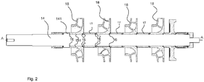
- FIG. 2 it is presented an embodiment of an impeller/ shaft assembly for a multistage centrifugal pump, such as presented in Fig. 1 .
- the impeller / shaft assembly comprises
- the impellers 18 there is provided a bush ring or bush rings 17.
- Bush rings may be used for bearing attachment or just as spacers between impellers.
- the impellers 18 and bush rings 17 form an axial array of tubular elements set on the shaft 14.
- the left end of the shaft 14 comprises a shaft collar 141 that forms an axial direction bracket for the array of impellers 18 and bush rings 17 to be tightened towards. This array is tightened from the right end of the shaft 14 with a tightening element, for example with a nut (not presented in the Fig. 2 ).
- the shaft 14 has a constant diameter at the length wherein the impellers 18 are configured to be assembled.
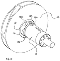
- FIG. 3 it is presented an embodiment of an impeller 18 / shaft 14 assembly for a multistage centrifugal pump.
- the Fig. 3 illustrates that the shaft 14 has a diameter that is smaller than the inner diameter of the hub 181 and adaptor ring 16 would be arranged into the axial opening 180 of the hub 181 to transmit the radial forces between the impeller 18 and the shaft 14.
- the hub 181 is provided with a circumferential cavity 182 or cavities 182 for the adaptor ring(s) 16 to fit in.
- the cavity 182 comprises radially inner surface which is parallel to the outer surface of the shaft 14 and the adaptor ring 16 has rectangular cross section.
- the torque (generated by a pump motor not shown in figures) is configured to be transmitted between the impeller 18 and the shaft 14 by a cotter joint 145.
- the adaptor ring 16 is a continuous ring or the adaptor ring 16 has a cut-out to form a C-shaped adaptor ring 16 to provide a passage for a cotter or key (not shown) between the hub 181 and the shaft 14. It depends for example on the cotter joint design which of the two options is more preferred for the adaptor ring 16 design, continuous ring or with a cut-out.
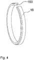
- Fig. 4 it is presented an embodiment of an adaptor ring 16.
- the function of the adaptor ring is to bear radial direction or compression forces between the impeller 18 and the shaft 14.
- the adaptor ring 16 has a cut-out 160 to form a C-shaped adaptor ring 16 to provide a passage for a cotter.
- the adaptor ring is made such material that is suitable for that kind of load, preferably it is made of composite material, steel or other metallic material.
- the adaptor ring 16 has a rectangular cross section so that it does not transfer any axial loads to radial loads or vice versa.
- the axial length of the adaptor ring is in a range 1/5 - 1/20 of the axial length of the hub 181, depending on the required strength dimensioning, material parameters, required load bearing capacity, etc..
Landscapes
- Engineering & Computer Science (AREA)
- Mechanical Engineering (AREA)
- General Engineering & Computer Science (AREA)
- Structures Of Non-Positive Displacement Pumps (AREA)
Priority Applications (6)
| Application Number | Priority Date | Filing Date | Title |
|---|---|---|---|
| EP21154000.0A EP4036420A1 (fr) | 2021-01-28 | 2021-01-28 | Pompe centrifuge à étages multiples de pompage de fluide, ensemble rotor/arbre et procédé d'assemblage d'un rotor/arbre |
| EP22701602.9A EP4285032B1 (fr) | 2021-01-28 | 2022-01-24 | Pompe centrifuge à étages multiples de pompage de fluide, ensemble rotor/arbre et procédé d'assemblage d'un rotor/arbre |
| FIEP22701602.9T FI4285032T3 (fi) | 2021-01-28 | 2022-01-24 | Monivaiheinen keskipakopumppu nesteen pumppaamiseen, juoksupyörä-/ akselikokoonpano ja menetelmä juoksupyörä-/akselikokoonpanon kokoamiseksi |
| US18/272,668 US12480494B2 (en) | 2021-01-28 | 2022-01-24 | Multistage centrifugal pump for pumping fluid, an impeller/ shaft assembly and a method for assembling an impeller/ shaft assembly |
| PCT/EP2022/051463 WO2022161905A1 (fr) | 2021-01-28 | 2022-01-24 | Pompe centrifuge à étages multiples pour pomper un fluide, ensemble roue/arbre et procédé d'assemblage d'un ensemble roue/arbre |
| CN202280010626.3A CN116724175A (zh) | 2021-01-28 | 2022-01-24 | 用于泵送流体的多级离心泵、叶轮/轴组件以及用于组装叶轮/轴组件的方法 |
Applications Claiming Priority (1)
| Application Number | Priority Date | Filing Date | Title |
|---|---|---|---|
| EP21154000.0A EP4036420A1 (fr) | 2021-01-28 | 2021-01-28 | Pompe centrifuge à étages multiples de pompage de fluide, ensemble rotor/arbre et procédé d'assemblage d'un rotor/arbre |
Publications (1)
| Publication Number | Publication Date |
|---|---|
| EP4036420A1 true EP4036420A1 (fr) | 2022-08-03 |
Family
ID=74346961
Family Applications (2)
| Application Number | Title | Priority Date | Filing Date |
|---|---|---|---|
| EP21154000.0A Withdrawn EP4036420A1 (fr) | 2021-01-28 | 2021-01-28 | Pompe centrifuge à étages multiples de pompage de fluide, ensemble rotor/arbre et procédé d'assemblage d'un rotor/arbre |
| EP22701602.9A Active EP4285032B1 (fr) | 2021-01-28 | 2022-01-24 | Pompe centrifuge à étages multiples de pompage de fluide, ensemble rotor/arbre et procédé d'assemblage d'un rotor/arbre |
Family Applications After (1)
| Application Number | Title | Priority Date | Filing Date |
|---|---|---|---|
| EP22701602.9A Active EP4285032B1 (fr) | 2021-01-28 | 2022-01-24 | Pompe centrifuge à étages multiples de pompage de fluide, ensemble rotor/arbre et procédé d'assemblage d'un rotor/arbre |
Country Status (5)
| Country | Link |
|---|---|
| US (1) | US12480494B2 (fr) |
| EP (2) | EP4036420A1 (fr) |
| CN (1) | CN116724175A (fr) |
| FI (1) | FI4285032T3 (fr) |
| WO (1) | WO2022161905A1 (fr) |
Citations (7)
| Publication number | Priority date | Publication date | Assignee | Title |
|---|---|---|---|---|
| US1448925A (en) * | 1922-03-29 | 1923-03-20 | Ingersoll Rand Co | Impeller mounting for centrifugal pumps |
| GB1364117A (en) | 1970-12-21 | 1974-08-21 | Borg Warner | Multistage centrifugal pumps |
| CN203189272U (zh) * | 2013-03-14 | 2013-09-11 | 山东硕博泵业有限公司 | 双壳体多级中开离心泵 |
| CN205331041U (zh) * | 2015-12-22 | 2016-06-22 | 山东长志泵业有限公司 | 易拆装轴向剖分多级离心泵叶轮定位装置 |
| CN206681995U (zh) * | 2017-04-07 | 2017-11-28 | 石家庄强大泵业集团有限责任公司 | 两级双吸中开式离心泵 |
| CN207049061U (zh) * | 2017-04-07 | 2018-02-27 | 兰州兰泵有限公司 | 一种多级离心泵的叶轮连接结构 |
| CN111828372A (zh) * | 2020-06-23 | 2020-10-27 | 北京航天动力研究所 | 一种超高转速液氢涡轮泵柔性转子 |
Family Cites Families (10)
| Publication number | Priority date | Publication date | Assignee | Title |
|---|---|---|---|---|
| US5722812A (en) * | 1996-06-20 | 1998-03-03 | Baker Hughes Incorporated | Abrasion resistant centrifugal pump |
| EP2256347A1 (fr) * | 2009-05-26 | 2010-12-01 | Siemens Aktiengesellschaft | Machine rotative et son procédé d'assemblage |
| US8616863B2 (en) * | 2011-03-29 | 2013-12-31 | Baker Hughes Incorporated | ESP with offset laterally loaded bearings |
| US10267315B2 (en) * | 2013-11-28 | 2019-04-23 | Acd, Llc | Cryogenic submerged pump for LNG, light hydrocarbon and other electrically non-conducting and non-corrosive fluids |
| US9845808B2 (en) * | 2013-12-10 | 2017-12-19 | Baker Hughes, A Ge Company, Llc | Spherical sleeve and bushing bearing for centrifugal pump stage |
| CA2950622C (fr) * | 2015-12-03 | 2020-01-07 | Halliburton Energy Services, Inc. | Systeme de blocage de roulement a ajustement serre, appareil et methode |
| DE102016111406A1 (de) * | 2016-06-22 | 2017-12-28 | Xylem Ip Management Sàrl | Bausatz für eine Pumpvorrichtung |
| WO2018058097A1 (fr) * | 2016-09-26 | 2018-03-29 | Fluid Handling Llc | Hélice à étages multiples produite par fabrication additive |
| CN207750243U (zh) * | 2017-12-08 | 2018-08-21 | 常州市洛锐电器有限公司 | 一种多级离心泵 |
| EP3686436A1 (fr) * | 2019-07-31 | 2020-07-29 | Sulzer Management AG | Pompe à plusieurs étages et agencement de pompage sous-marin |
-
2021
- 2021-01-28 EP EP21154000.0A patent/EP4036420A1/fr not_active Withdrawn
-
2022
- 2022-01-24 US US18/272,668 patent/US12480494B2/en active Active
- 2022-01-24 CN CN202280010626.3A patent/CN116724175A/zh active Pending
- 2022-01-24 WO PCT/EP2022/051463 patent/WO2022161905A1/fr not_active Ceased
- 2022-01-24 EP EP22701602.9A patent/EP4285032B1/fr active Active
- 2022-01-24 FI FIEP22701602.9T patent/FI4285032T3/fi active
Patent Citations (7)
| Publication number | Priority date | Publication date | Assignee | Title |
|---|---|---|---|---|
| US1448925A (en) * | 1922-03-29 | 1923-03-20 | Ingersoll Rand Co | Impeller mounting for centrifugal pumps |
| GB1364117A (en) | 1970-12-21 | 1974-08-21 | Borg Warner | Multistage centrifugal pumps |
| CN203189272U (zh) * | 2013-03-14 | 2013-09-11 | 山东硕博泵业有限公司 | 双壳体多级中开离心泵 |
| CN205331041U (zh) * | 2015-12-22 | 2016-06-22 | 山东长志泵业有限公司 | 易拆装轴向剖分多级离心泵叶轮定位装置 |
| CN206681995U (zh) * | 2017-04-07 | 2017-11-28 | 石家庄强大泵业集团有限责任公司 | 两级双吸中开式离心泵 |
| CN207049061U (zh) * | 2017-04-07 | 2018-02-27 | 兰州兰泵有限公司 | 一种多级离心泵的叶轮连接结构 |
| CN111828372A (zh) * | 2020-06-23 | 2020-10-27 | 北京航天动力研究所 | 一种超高转速液氢涡轮泵柔性转子 |
Also Published As
| Publication number | Publication date |
|---|---|
| EP4285032A1 (fr) | 2023-12-06 |
| FI4285032T3 (fi) | 2025-05-21 |
| US12480494B2 (en) | 2025-11-25 |
| CN116724175A (zh) | 2023-09-08 |
| US20250075702A1 (en) | 2025-03-06 |
| EP4285032B1 (fr) | 2025-03-05 |
| WO2022161905A1 (fr) | 2022-08-04 |
Similar Documents
| Publication | Publication Date | Title |
|---|---|---|
| EP2031251B1 (fr) | Couplage à cannelures avec des élements antirotation | |
| EP3001037B1 (fr) | Pompe électrique à fluide avec rotor amélioré et procédé de construction de celle-ci | |
| EP1980721B2 (fr) | Ensemble d'aube de stator orientable pour moteur de turbine | |
| US10794390B2 (en) | Modular turbo compressor shaft | |
| US5344285A (en) | Centrifugal pump with monolithic diffuser and return vane channel ring member | |
| US3861825A (en) | Multistage pump and manufacturing method | |
| US7086830B2 (en) | Tube-type vortex reducer with retaining ring | |
| EP2872744B1 (fr) | Rotor destiné à un compresseur radial et procédé de construction associé | |
| CA2874009C (fr) | Palier a bague et manchon spherique pour etage de pompe centrifuge | |
| EP3592982B1 (fr) | Agencement de palier pour un arbre de transmission d'une turbomachine, et turbomachine équipée d'un tel agencement de palier | |
| EP3358195B1 (fr) | Compresseur centrifuge | |
| CN105952752A (zh) | 与复合工作构件一起使用的具有光滑轮廓的金属嵌件 | |
| EP4285032B1 (fr) | Pompe centrifuge à étages multiples de pompage de fluide, ensemble rotor/arbre et procédé d'assemblage d'un rotor/arbre | |
| US11346364B2 (en) | Multistage centrifugal fluid machine | |
| US6540474B2 (en) | Side-channel pump | |
| US10494937B2 (en) | Inner ring for an annular guide vane assembly of a turbomachine | |
| EP1106780B1 (fr) | Transmission du couple dans un rotor de turbine | |
| EP1050665A2 (fr) | Dispositif de fixation des tubes de refroidissement dans un rotor d'une turbine à gaz | |
| WO2015163999A1 (fr) | Boîtier universel pour un compresseur de gaz centrifuge | |
| CN101832272B (zh) | 多级离心泵组 | |
| EP3364036A1 (fr) | Logement de palier à fente axiale et machine rotative | |
| WO2018162660A1 (fr) | Agencement d'impulseurs à deux étages pour un turbocompresseur centrifuge à deux étages | |
| EP4038281B1 (fr) | Système de retenue de douille | |
| JP6351915B1 (ja) | 回転子部材及び回転電機 | |
| US11773702B2 (en) | Motor bearing with anti-rotation spring for electrical submersible well pump |
Legal Events
| Date | Code | Title | Description |
|---|---|---|---|
| PUAI | Public reference made under article 153(3) epc to a published international application that has entered the european phase |
Free format text: ORIGINAL CODE: 0009012 |
|
| STAA | Information on the status of an ep patent application or granted ep patent |
Free format text: STATUS: THE APPLICATION HAS BEEN PUBLISHED |
|
| AK | Designated contracting states |
Kind code of ref document: A1 Designated state(s): AL AT BE BG CH CY CZ DE DK EE ES FI FR GB GR HR HU IE IS IT LI LT LU LV MC MK MT NL NO PL PT RO RS SE SI SK SM TR |
|
| STAA | Information on the status of an ep patent application or granted ep patent |
Free format text: STATUS: THE APPLICATION IS DEEMED TO BE WITHDRAWN |
|
| 18D | Application deemed to be withdrawn |
Effective date: 20230204 |