EP4036683A1 - Composant pliable et terminal d'affichage pliable - Google Patents
Composant pliable et terminal d'affichage pliable Download PDFInfo
- Publication number
- EP4036683A1 EP4036683A1 EP20879803.3A EP20879803A EP4036683A1 EP 4036683 A1 EP4036683 A1 EP 4036683A1 EP 20879803 A EP20879803 A EP 20879803A EP 4036683 A1 EP4036683 A1 EP 4036683A1
- Authority
- EP
- European Patent Office
- Prior art keywords
- mechanical part
- protective structure
- flexible display
- rotating shaft
- foldable
- Prior art date
- Legal status (The legal status is an assumption and is not a legal conclusion. Google has not performed a legal analysis and makes no representation as to the accuracy of the status listed.)
- Granted
Links
Images


Classifications
-
- G—PHYSICS
- G09—EDUCATION; CRYPTOGRAPHY; DISPLAY; ADVERTISING; SEALS
- G09F—DISPLAYING; ADVERTISING; SIGNS; LABELS OR NAME-PLATES; SEALS
- G09F9/00—Indicating arrangements for variable information in which the information is built-up on a support by selection or combination of individual elements
- G09F9/30—Indicating arrangements for variable information in which the information is built-up on a support by selection or combination of individual elements in which the desired character or characters are formed by combining individual elements
- G09F9/301—Indicating arrangements for variable information in which the information is built-up on a support by selection or combination of individual elements in which the desired character or characters are formed by combining individual elements flexible foldable or roll-able electronic displays, e.g. thin LCD, OLED
-
- G—PHYSICS
- G06—COMPUTING OR CALCULATING; COUNTING
- G06F—ELECTRIC DIGITAL DATA PROCESSING
- G06F1/00—Details not covered by groups G06F3/00 - G06F13/00 and G06F21/00
- G06F1/16—Constructional details or arrangements
- G06F1/1613—Constructional details or arrangements for portable computers
- G06F1/1615—Constructional details or arrangements for portable computers with several enclosures having relative motions, each enclosure supporting at least one I/O or computing function
- G06F1/1616—Constructional details or arrangements for portable computers with several enclosures having relative motions, each enclosure supporting at least one I/O or computing function with folding flat displays, e.g. laptop computers or notebooks having a clamshell configuration, with body parts pivoting to an open position around an axis parallel to the plane they define in closed position
-
- G—PHYSICS
- G06—COMPUTING OR CALCULATING; COUNTING
- G06F—ELECTRIC DIGITAL DATA PROCESSING
- G06F1/00—Details not covered by groups G06F3/00 - G06F13/00 and G06F21/00
- G06F1/16—Constructional details or arrangements
- G06F1/1613—Constructional details or arrangements for portable computers
- G06F1/1633—Constructional details or arrangements of portable computers not specific to the type of enclosures covered by groups G06F1/1615 - G06F1/1626
- G06F1/1637—Details related to the display arrangement, including those related to the mounting of the display in the housing
- G06F1/1641—Details related to the display arrangement, including those related to the mounting of the display in the housing the display being formed by a plurality of foldable display components
-
- G—PHYSICS
- G06—COMPUTING OR CALCULATING; COUNTING
- G06F—ELECTRIC DIGITAL DATA PROCESSING
- G06F1/00—Details not covered by groups G06F3/00 - G06F13/00 and G06F21/00
- G06F1/16—Constructional details or arrangements
- G06F1/1613—Constructional details or arrangements for portable computers
- G06F1/1633—Constructional details or arrangements of portable computers not specific to the type of enclosures covered by groups G06F1/1615 - G06F1/1626
- G06F1/1637—Details related to the display arrangement, including those related to the mounting of the display in the housing
- G06F1/1652—Details related to the display arrangement, including those related to the mounting of the display in the housing the display being flexible, e.g. mimicking a sheet of paper, or rollable
-
- G—PHYSICS
- G06—COMPUTING OR CALCULATING; COUNTING
- G06F—ELECTRIC DIGITAL DATA PROCESSING
- G06F1/00—Details not covered by groups G06F3/00 - G06F13/00 and G06F21/00
- G06F1/16—Constructional details or arrangements
- G06F1/1613—Constructional details or arrangements for portable computers
- G06F1/1633—Constructional details or arrangements of portable computers not specific to the type of enclosures covered by groups G06F1/1615 - G06F1/1626
- G06F1/1656—Details related to functional adaptations of the enclosure, e.g. to provide protection against EMI, shock, water, or to host detachable peripherals like a mouse or removable expansions units like PCMCIA cards, or to provide access to internal components for maintenance or to removable storage supports like CDs or DVDs, or to mechanically mount accessories
-
- G—PHYSICS
- G06—COMPUTING OR CALCULATING; COUNTING
- G06F—ELECTRIC DIGITAL DATA PROCESSING
- G06F1/00—Details not covered by groups G06F3/00 - G06F13/00 and G06F21/00
- G06F1/16—Constructional details or arrangements
- G06F1/1613—Constructional details or arrangements for portable computers
- G06F1/1633—Constructional details or arrangements of portable computers not specific to the type of enclosures covered by groups G06F1/1615 - G06F1/1626
- G06F1/1675—Miscellaneous details related to the relative movement between the different enclosures or enclosure parts
- G06F1/1681—Details related solely to hinges
-
- H—ELECTRICITY
- H04—ELECTRIC COMMUNICATION TECHNIQUE
- H04M—TELEPHONIC COMMUNICATION
- H04M1/00—Substation equipment, e.g. for use by subscribers
- H04M1/02—Constructional features of telephone sets
- H04M1/0202—Portable telephone sets, e.g. cordless phones, mobile phones or bar type handsets
- H04M1/0206—Portable telephones comprising a plurality of mechanically joined movable body parts, e.g. hinged housings
- H04M1/0208—Portable telephones comprising a plurality of mechanically joined movable body parts, e.g. hinged housings characterized by the relative motions of the body parts
- H04M1/0214—Foldable telephones, i.e. with body parts pivoting to an open position around an axis parallel to the plane they define in closed position
- H04M1/0216—Foldable in one direction, i.e. using a one degree of freedom hinge
-
- H—ELECTRICITY
- H04—ELECTRIC COMMUNICATION TECHNIQUE
- H04M—TELEPHONIC COMMUNICATION
- H04M1/00—Substation equipment, e.g. for use by subscribers
- H04M1/02—Constructional features of telephone sets
- H04M1/0202—Portable telephone sets, e.g. cordless phones, mobile phones or bar type handsets
- H04M1/026—Details of the structure or mounting of specific components
- H04M1/0266—Details of the structure or mounting of specific components for a display module assembly
- H04M1/0268—Details of the structure or mounting of specific components for a display module assembly including a flexible display panel
-
- H—ELECTRICITY
- H04—ELECTRIC COMMUNICATION TECHNIQUE
- H04M—TELEPHONIC COMMUNICATION
- H04M1/00—Substation equipment, e.g. for use by subscribers
- H04M1/02—Constructional features of telephone sets
- H04M1/18—Telephone sets specially adapted for use in ships, mines, or other places exposed to adverse environment
- H04M1/185—Improving the shock resistance of the housing, e.g. by increasing the rigidity
-
- H—ELECTRICITY
- H05—ELECTRIC TECHNIQUES NOT OTHERWISE PROVIDED FOR
- H05K—PRINTED CIRCUITS; CASINGS OR CONSTRUCTIONAL DETAILS OF ELECTRIC APPARATUS; MANUFACTURE OF ASSEMBLAGES OF ELECTRICAL COMPONENTS
- H05K5/00—Casings, cabinets or drawers for electric apparatus
- H05K5/0017—Casings, cabinets or drawers for electric apparatus with operator interface units
-
- H—ELECTRICITY
- H05—ELECTRIC TECHNIQUES NOT OTHERWISE PROVIDED FOR
- H05K—PRINTED CIRCUITS; CASINGS OR CONSTRUCTIONAL DETAILS OF ELECTRIC APPARATUS; MANUFACTURE OF ASSEMBLAGES OF ELECTRICAL COMPONENTS
- H05K5/00—Casings, cabinets or drawers for electric apparatus
- H05K5/02—Details
- H05K5/0217—Mechanical details of casings
-
- H—ELECTRICITY
- H10—SEMICONDUCTOR DEVICES; ELECTRIC SOLID-STATE DEVICES NOT OTHERWISE PROVIDED FOR
- H10K—ORGANIC ELECTRIC SOLID-STATE DEVICES
- H10K50/00—Organic light-emitting devices
- H10K50/80—Constructional details
- H10K50/84—Passivation; Containers; Encapsulations
-
- H—ELECTRICITY
- H10—SEMICONDUCTOR DEVICES; ELECTRIC SOLID-STATE DEVICES NOT OTHERWISE PROVIDED FOR
- H10K—ORGANIC ELECTRIC SOLID-STATE DEVICES
- H10K2102/00—Constructional details relating to the organic devices covered by this subclass
- H10K2102/301—Details of OLEDs
- H10K2102/311—Flexible OLED
-
- H—ELECTRICITY
- H10—SEMICONDUCTOR DEVICES; ELECTRIC SOLID-STATE DEVICES NOT OTHERWISE PROVIDED FOR
- H10K—ORGANIC ELECTRIC SOLID-STATE DEVICES
- H10K59/00—Integrated devices, or assemblies of multiple devices, comprising at least one organic light-emitting element covered by group H10K50/00
- H10K59/10—OLED displays
- H10K59/12—Active-matrix OLED [AMOLED] displays
-
- H—ELECTRICITY
- H10—SEMICONDUCTOR DEVICES; ELECTRIC SOLID-STATE DEVICES NOT OTHERWISE PROVIDED FOR
- H10K—ORGANIC ELECTRIC SOLID-STATE DEVICES
- H10K77/00—Constructional details of devices covered by this subclass and not covered by groups H10K10/80, H10K30/80, H10K50/80 or H10K59/80
- H10K77/10—Substrates, e.g. flexible substrates
- H10K77/111—Flexible substrates
Definitions
- This application relates to the field of display technologies, and in particular, to a foldable assembly and a foldable display terminal.
- a foldable display terminal gradually becomes a development trend of future mobile electronic products.
- a large display area improves a video watching effect.
- a small size makes the terminal convenient for a user to carry.
- the foldable display terminal includes at least a flexible display and a foldable assembly configured to bear the flexible display.
- the flexible display is fragile, and is easy to damage and fail.
- the foldable display terminal inevitably falls, and consequently, the flexible display is damaged.
- a foldable display terminal of an outward-foldable design because a flexible display is exposed outside, there is a more prominent problem that damage is caused by a fall, and consequently, user experience is affected.
- Embodiments of this application provide a foldable assembly and a foldable display terminal, to resolve a problem that a flexible display is damaged due to a fall of the foldable display terminal and user experience is affected.
- a foldable assembly is provided.
- the foldable assembly is configured to bear a flexible display
- the foldable assembly includes: a rotating shaft; a first mechanical part and a second mechanical part, where the first mechanical part and the second mechanical part are rotatably connected by using the rotating shaft; and a first protective structure, where the first protective structure is connected to an end face that is of the rotating shaft and that extends out of a periphery of the flexible display, the flexible display includes a first surface that is away from the rotating shaft, and the first protective structure is higher than or flush with the first surface of the flexible display.
- the first protective structure is disposed, to protect the flexible display, and avoid a case in which the flexible display is damaged due to a fall of a foldable display terminal.
- the flexible display is most easily damaged when the foldable display terminal in a folded state falls at an angle.
- the first protective structure provided in this embodiment of this application is located at a bending angle of the flexible display, and the first protective structure is higher than or flush with a surface that is of the flexible display and that is away from the bent region support, so that when the foldable display terminal falls, the first protective structure is in contact with a point of collision earlier than the flexible display, to enhance protection of the flexible display and further improve anti-collision performance of the foldable display terminal.
- a material of the first protective structure is stainless steel, die steel, or an amorphous alloy. Therefore, strength of the first protective structure is improved, and the anti-collision performance of the foldable display terminal is improved.
- the first protective structure and the rotating shaft are integrally formed. Therefore, a connection manner in which the first protective structure and the rotating shaft are integrally formed provides higher strength, and the anti-collision performance of the foldable display terminal is further improved.
- the foldable assembly further includes a second protective structure and a third protective structure.
- the second protective structure is connected to an end face that is of the first mechanical part and that extends out of the periphery of the flexible display, and the second protective structure is higher than or flush with a surface that is of the flexible display and that is away from the first mechanical part; and the third protective structure is connected to an end face that is of the second mechanical part and that extends out of the periphery of the flexible display, and the third protective structure is higher than or flush with a surface that is of the flexible display and that is away from the second mechanical part. Therefore, the second protective structure and the third protective structure are disposed, to protect the periphery of the flexible display.
- the second protective structure and the third protective structure are higher than or flush with the surface that is of the flexible display and that is away from the second mechanical part.
- the second protective structure and the third protective structure may be in contact with the point of collision earlier than the flexible display, to enhance the protection of the flexible display, and further improve the anti-collision performance of the foldable display terminal.
- the second protective structure and the first mechanical part are integrally formed, and the third protective structure and the second mechanical part are integrally formed. Therefore, a connection manner in which the second protective structure and the first mechanical part are integrally formed provides higher strength, and the anti-collision performance of the foldable display terminal is further improved.
- a material of each of the second protective structure and the third protective structure is an aluminum alloy. Therefore, strength of the first protective structure is improved, and the anti-collision performance of the foldable display terminal is improved.
- a first protrusion is disposed on the first mechanical part, a first groove matching the first protrusion is disposed on the rotating shaft, and the first protrusion is located in the first groove; and a second protrusion is disposed on the second mechanical part, a second groove matching the second protrusion is disposed on the rotating shaft, and the second protrusion is located in the second groove. Therefore, the first groove matches the first protrusion, and the second groove matches the second protrusion, so that when the foldable display terminal falls, displacement and dislocation amounts of the first mechanical part and the second mechanical part relative to the rotating shaft can be greatly reduced, and a case in which the flexible display is damaged by shear force exerted on the flexible display due to a fall of the foldable display terminal is avoided.
- the foldable assembly further includes: a third mechanical part, where the first mechanical part is provided with a first sliding groove, a first end of the third mechanical part is connected to the rotating shaft, and a second end of the third mechanical part is disposed in the first sliding groove; and a fourth mechanical part, where the second mechanical part is provided with a second sliding groove, a first end of the fourth mechanical part is connected to the rotating shaft, and a second end of the fourth mechanical part is disposed in the second sliding groove.
- the third mechanical part is slidably connected to the first mechanical part
- the fourth mechanical part is slidably connected to the second mechanical part, so that when the flexible display is folded or unfolded, the first mechanical part can slide relative to the third mechanical part, and the second mechanical part can slide relative to the fourth mechanical part, to reduce pulling force exerted by the first mechanical part, the second mechanical part, and the rotating shaft on the flexible display, avoid a case in which the flexible display is damaged when being pulled, and improve flatness of the flexible display.
- the foldable display terminal further includes: a bent region support, located on a side that is of a rotating part and that faces the flexible display, and connected to the rotating shaft, the first mechanical part, and the second mechanical part, where the bent region support includes a flexible connection layer and a plurality of spaced rigid support bars disposed along an axis direction of the rotating shaft; the rigid support bar is connected to the flexible connection layer; and the flexible connection layer is connected to a bent region of the flexible display by using an adhesive layer.
- the bent region support may be flexible to an extent because of a flexible material layer, to ensure that a maximum bending angle of the bent region of the flexible display can meet a requirement, and the rigid support bar can provide strong rigidity for the bent region support, so that the bent region support has good support performance, and an impact resistance capability of the bent region of the flexible display in a bending process of the foldable display terminal is improved.
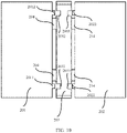
- an elastic component is disposed between an end face of the bent region support and the first protective structure. Therefore, the elastic component is disposed between the bent region support and the first protective structure, to cushion the fall of the foldable display terminal, and protect the bent region support.
- a foldable display terminal including a flexible display and the foregoing foldable assembly.
- a first non-bent region of the flexible display is connected to a first mechanical part in the foldable assembly;
- a second non-bent region of the flexible display is connected to a second mechanical part in the foldable assembly;
- a bent region of the flexible display is connected to a bent region support in the foldable assembly; and the bent region is located between the first non-bent region and the second non-bent region. Therefore, the foldable assembly is used by the foldable display terminal, to improve anti-collision performance of the foldable display terminal.
- first”, “second”, and the like are merely intended for a purpose of description, and shall not be understood as an indication or implication of relative importance or implicit indication of a quantity of indicated technical features. Therefore, a feature limited by “first”, “second”, or the like may explicitly or implicitly include one or more features. In the description of this application, unless otherwise stated, "a plurality of' means two or more than two.
- the foldable display terminal may be a product having a display screen, such as a mobile phone, a display, a tablet computer, or a vehicle-mounted computer.
- a specific form of the foldable display terminal is not particularly limited in this embodiment of this application.
- a foldable display terminal 01 includes a flexible display 10.
- the flexible display 10 may be an active matrix organic light emitting diode (active matrix organic light emitting diode, AMOLED) display.
- the AMOLED display is a self-luminous display, a back light module (back light module, BLM) is not required to be disposed in the AMOLED display. Therefore, when a base substrate of the AMOLED display is made from a flexible resin material, for example, polyethylene terephthalate (polyethylene terephthalate, PET), the AMOLED display may be bendable.
- BLM back light module
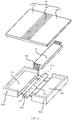
- the foldable display terminal 01 further includes a foldable assembly 20 configured to bear the flexible display 10.
- the foldable assembly 20 includes a first mechanical part 201, a second mechanical part 202, and a rotating shaft 203 located between the first mechanical part 201 and the second mechanical part 202.
- the rotating shaft 203 is connected to the first mechanical part 201 and the second mechanical part 202.
- the first mechanical part 201 and the second mechanical part 202 may separately rotate around the rotating shaft 203.
- the first mechanical part 201 and the second mechanical part 202 may be housings, or may be middle frame structures of an electronic device.
- the first mechanical part 201 and the second mechanical part 202 may be configured to bear the flexible display 10, so that the flexible display 10 remains as flat as possible in a use process, and a non-display surface of the flexible display 10 is protected.
- the adhesive layer may be a thin film layer formed after an adhesive is applied.
- a specific form of the adhesive layer is not limited in this embodiment of this application.
- another electronic element such as a camera, a headset, a receiver, a button, or a battery may be disposed on the first mechanical part 201 and the second mechanical part 202.
- the another electronic element disposed on the first mechanical part 201 and the second mechanical part 202 are not limited in this embodiment of this application.
- the first mechanical part 201 and the second mechanical part 202 may rotate along an axis O-O of the rotating shaft 203, to drive the flexible display 10 to be folded or unfolded.
- the flexible display may be folded or unfolded.
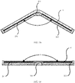
- FIG. 1a shows an unfolding process of unfolding the flexible display from 180° to 0°, or a folding process of folding the flexible display from 0° to 180°.
- an area, of the flexible display 10, that is connected to the first mechanical part 201 by using the adhesive layer cannot be bent.
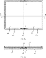
- the area is a first non-bent area 101 shown in FIG. 2 .
- the area is a second non-bent area 102 shown in FIG. 2 .
- a part, of the flexible display 10, that is located between the first non-bent area 101 and the second non-bent area 102 is a bent area 103 that can enable the foldable display terminal 01 to be bent.
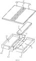
- the foldable assembly 20 further includes a bent region support 30.
- the bent region support 30 is located on a side, facing the flexible display 10, of the rotating shaft 203.
- the bent region support 30 is further connected to the first mechanical part 201 and the second mechanical part 202.
- one end that is of the bent region support 30 and that is close to the first mechanical part 201 may be bonded to the first mechanical part 201 by using an adhesive layer.
- One end that is of the bent region support 30 and that is close to the second mechanical part 202 may be bonded to the second mechanical part 202 by using an adhesive layer.
- the bent region support 30 needs to support the bent area 103, so that in a bending process of the foldable display terminal 01, the bent area 103 of the flexible display 10 has a good impact resistance capability, and a probability that the flexible display 10 is damaged in the bent area 103 is reduced.
- the bent region support 30 further needs to have good flexibility, to ensure that a maximum bending angle of the bent area 103 of the flexible display 10 can meet a requirement.
- a maximum bending angle of the bent area 103 of the flexible display 10 can meet a requirement.
- the bent region support 30 includes a flexible connection layer 301, and a plurality of spaced rigid support bars 302 that are disposed along a direction of the axis O-O of the rotating shaft 203.
- the plurality of rigid support bars 302 are disposed at intervals, and each rigid support bar 302 is connected to the flexible connection layer 301.
- the flexible connection layer 301 wraps the plurality of rigid support bars 302. In this case, a periphery of each rigid support bar 302 is covered by the flexible connection layer 301.
- Rigidity of a material constituting the rigid support bar 302 is greater than rigidity of a material constituting the flexible connection layer 301.
- a material of the rigid support bar 302 may be a metal simple substance, for example, tungsten or molybdenum; or may be a metal compound, for example, alloy steel such as stainless steel or die steel, or an amorphous alloy.
- the material constituting the flexible connection layer 301 may be a silicone material with high flexibility. In this way, the flexible material layer 301 may enable the bent region support 30 to be flexible, to ensure that the maximum bending angle of the bent area 103 of the flexible display 10 can meet the requirement.
- the rigid support bars 302 may provide strong rigidity for the bent region support 30, so that the bent region support 30 has good support performance, to improve the impact resistance capability of the bent area 103 of the flexible display 10 in the bending process of the foldable display terminal 01.
- the flexible display 10 is fragile, and the flexible display 10 is prone to damage when the foldable display terminal falls.
- the flexible display is most easily damaged when the foldable display terminal that is of an outward-foldable design and that is in a folded state falls at an angle.
- the flexible display is located on an outside of the device.
- the flexible display 10 To avoid a case in which the flexible display 10 is damaged when the foldable display terminal falls, the flexible display 10 needs to be provided with a protective structure.
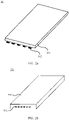
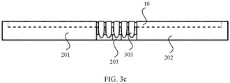
- a protective structure 303 may be disposed on an end face that is of the bent region support 30 and that extends out of a periphery of the flexible display 10.
- the protective structure 303 separately extends from the end face of the bent region support 30 to an end face of the flexible display 10 and an end face of the rotating shaft 203, and the protective structure 303 and the bent region support 30 are arranged in a shape "T".
- the protective structure 303 is disposed, to protect the bent area 103 of the flexible display, and avoid a case in which the flexible display is damaged when the foldable display terminal falls.
- the protective structure 303 provided in this embodiment of this application is located at a bending angle of the flexible display, to protect the bending angle of the flexible display, and in particular, protect, in a case of a fall at an angle, the foldable display terminal that is of the outward-foldable design and that is in the folded state, and improve anti-collision performance of the foldable display terminal.
- the protective structure 303 is higher than or flush with a surface that is of the flexible display 10 and that is away from the bent region support 30, so that when the foldable display terminal falls, the protective structure 303 is in contact with a point of collision earlier than the flexible display, to enhance protection of the flexible display, and further improve anti-collision performance of the foldable display terminal.
- a connection manner of the protective structure 303 and the bent region support 30 is not limited in this embodiment of this application.
- the protective structure 303 and the bent region support 30 are separately formed, and the protective structure 303 and the rigid support bar 302 of the bent region support 30 may be connected through welding.
- the protective structure 303 and the rigid support bar 302 of the bent region support 30 are integrally formed. In this case, strength of a connection point of the protective structure 303 and the bent region support 30 can be increased.
- a material of the protective structure 303 is not limited in this embodiment of this application.
- the material of the protective structure 303 includes but is not limited to alloy steel such as stainless steel or die steel, or an amorphous alloy.
- the protective structure 303 may be injection molded by using a metal injection molding (Metal injection Molding, MIM) process. During molding, metal powder and a plasticized compound of a binder may be mixed first, and then a mixture is granulated and then injected to obtain a desired shape.
- MIM Metal injection Molding
- a quantity of protective structures 303 is the same as a quantity of rigid support bars 302, and one protective structure 303 is connected to an end face of each rigid support bar. There is a complex process.
- a part that is of the rigid support bar 302 and that is subjected to impact of a fall may be strengthened, or the rotating shaft is used to assist in limiting on a rear side of the rigid support bar 302, to share a part of the impact of a fall, or as shown in FIG. 5 , a gap between the flexible display 10 and the protective structure 303 is increased, to leave a large safety margin.
- an embodiment of this application further provides a protective structure of a flexible display.
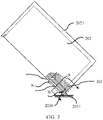
- a difference between the protective structure in this embodiment and the protective structure 303 provided on the end face of the bent region support 30 is that a first protective structure 2031 in this embodiment is disposed on an end face that is of the rotating shaft 203 and that extends from the periphery of the flexible display 10, and the first protective structure 2031 extends from the end of the rotating shaft 203 to the end face of the flexible display 10, so that the first protective structure 2031 and the rotating shaft 203 are arranged in a shape of "L".
- the first protective structure 2031 is disposed, to protect the bent area 103 of the flexible display, and avoid a case in which the flexible display is damaged when the foldable display terminal falls.
- the first protective structure 2031 provided in this embodiment of this application is located at the bending angle of the flexible display, to protect the bending angle of the flexible display, and in particular, protect the foldable display terminal in the folded state in a case of the fall at an angle, and improve anti-collision performance of the foldable display terminal.
- the first protective structure 2031 is higher than or flush with the surface that is of the flexible display 10 and that is away from the bent region support 30, so that when the foldable display terminal falls, the first protective structure 2031 is in contact with a point of collision earlier than the flexible display, to enhance protection of the flexible display, and further improve anti-collision performance of the foldable display terminal.
- a dimension of the first protective structure is not limited in this embodiment of this application. As shown in FIG. 8 , a vertex 2030 of the first protective structure 2031 is first in contact with the ground in a fall, and is subjected to greatest impact. Therefore, an area or a thickness of the vertex 2030 may be properly increased, or a dimension of the entire first protective structure 2031 is adjusted to increase a force receiving area, to improve impact resistance performance of the foldable display terminal.
- a connection manner of the first protective structure 2031 and the rotating shaft 203 is not limited in this embodiment of this application.
- a material of the first protective structure 2031 is the same as a material of the rotating shaft 203.
- the first protective structure 2031 and the rotating shaft 203 may be separately formed first, and then the first protective structure 2031 and the rotating shaft 203 are connected through welding.
- the first protective structure 2031 and the rotating shaft 203 are integrally formed. Therefore, strength of a connection point of the first protective structure 2031 and the rotating shaft 203 can be improved.
- a material of the first protective structure 2031 is not limited in this embodiment of this application.
- the material of the first protective structure 2031 includes but is not limited to alloy steel such as stainless steel or die steel, or an amorphous alloy.
- the first protective structure 2031 may be injection molded by using a metal injection molding (Metal injection Molding, MIM) process. During molding, metal powder and a plasticized compound of a binder may be mixed first, and then a mixture is granulated and then injected to obtain a desired shape.
- MIM Metal injection Molding
- a part that is of the first protective structure 2031 in this embodiment and that is subjected to impact of a fall changes from the protective structure 303 on the rigid support bar 302 to the first protective structure 2031 on the rotating shaft 203.
- a connection location of the protective structure 303 and the rigid support bar 302 is a weakest point of strength of a part that is of the foldable display terminal and that is subjected to impact.
- a connection location of the first protective structure 2031 and the rotating shaft 203 is a weakest point of strength of the part that is of the foldable display terminal and that is subjected to impact.
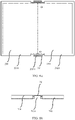
- a dimension of a connection face of the first protective structure 2031 and the rotating shaft 203 is greater than a dimension of a connection face of the protective structure 303 and the rigid support bar 302, to help improve impact resistance performance of the foldable display terminal.
- the dimension of the connection face of the protective structure 303 and the rigid support bar 302 and a cross-sectional dimension of the rigid support bar 302 may be represented as c ⁇ d.
- the dimension of the connection face of the first protective structure 2031 and the rotating shaft 203 and a cross-sectional dimension of the rotating shaft 203 may be represented as a ⁇ b. Because the rotating shaft 203 does not need to be folded following the flexible display, the cross-sectional dimension a ⁇ b of the rotating shaft 203 is larger than the cross-sectional dimension c ⁇ d of the rigid support bar.
- the connection face of the first protective structure 2031 and the rotating shaft 203 is approximately 5 to 6 times of the dimension of the connection face of the protective structure 303 and the rigid support bar 302, and strength of the rotating shaft 203 is approximately 5 to 6 times of strength of the rigid support bar in a case of a same material, to greatly improve anti-collision performance in a fall.
- the first protective structure connected to the rotating shaft 203 is disposed.
- strength of the part that is subjected to impact is increased by 5 to 6 times in the fall at an angle, to avoid a case in which the flexible display is damaged due to a fracture and deformation of the part.
- the end face of the bent region support 30 may be retracted, and an elastic component 40 is disposed between the end face of the bent region support and the frame.
- a material of the elastic component includes but is not limited to silica gel.
- the elastic component is disposed, to cushion a fall.
- the end face of the bent region support 30 is retracted, and the first protective structure 2031 is disposed outside the bent region support.
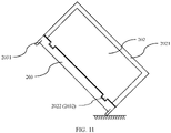
- a second protective structure 2011 may be further disposed on the end face that is of the first mechanical part 201 and that extends from the periphery of the flexible display 10
- a third protective structure 2021 may be disposed on an end face that is of the second mechanical part 202 and that extends from the periphery of the flexible display 10.
- the second protective structure and the third protective structure are disposed, to protect the periphery of the flexible display.
- the second protective structure 2011 is higher than or flush with a surface that is of the flexible display and that is away from the first mechanical part 201.
- the third protective structure 2021 is higher than or flush with a surface that is of the flexible display and that is away from the second mechanical part.
- the second protective structure and the third protective structure may be in contact with a point of collision earlier than the flexible display, to enhance protection of the flexible display, and further improve anti-collision performance of the foldable display terminal.
- connection manner of the second protective structure 2011 and the second mechanical part 202 and a connection manner of the third protective structure 2021 and the second mechanical part 202 are not limited in this embodiment of this application.
- a material of the second protective structure 2011 is the same as a material of the first mechanical part 201.
- the second protective structure 2011 and the first mechanical part 201 may be separately formed first, and then the second protective structure 2011 and the first mechanical part 201 are connected through welding.
- a material of the third protective structure 2021 is the same as the material of the second mechanical part 202.
- the third protective structure 2021 and the second mechanical part 202 may be separately formed first, and then the third protective structure 2021 and the second mechanical part 202 may be connected through welding.
- the second protective structure 2011 and the second mechanical part 202 are integrally formed. Therefore, connection strength of the second protective structure 2011 and the second mechanical part 202 can be improved, and the anti-collision performance of the foldable display terminal is further improved.
- the third protective structure 2021 and the second mechanical part 202 are integrally formed. Therefore, connection strength of the third protective structure 2021 and the second mechanical part 202 can be improved, and anti-collision performance of the foldable display terminal is further improved.
- the material of the second protective structure 2011 and the material of the third protective structure 2021 are not limited in this embodiment of this application.
- the material of the second protective structure 2011 and the material of the third protective structure 2021 include but are not limited to an aluminum alloy.
- the second protective structure 2011 and the third protective structure 2021 may be formed through diecasting or obtained through numerical control machining.
- the foldable assembly further includes a stop block.
- the stop block includes a protrusion and a groove.
- the protrusion is disposed on the first mechanical part 201 and the second mechanical part 202, and the groove is disposed on the rotating shaft.
- first protrusions 2012 are disposed on the first mechanical part 201, and two first grooves 2032 matching the first protrusions 2012 are disposed on the rotating shaft
- the first protrusion 2012 is located in the first groove 2032, to form a limiting structure, to prevent the first mechanical part 201 from being displaced and dislocated relative to the rotating shaft 203.
- two second protrusions 2022 are disposed on the second mechanical part 202, and two second grooves 2033 matching the second protrusions 2022 are disposed on the rotating shaft 203.
- the second protrusions 2022 are located in the second grooves 2033, to form a limiting structure, to prevent the second mechanical part 202 from being displaced and dislocated relative to the rotating shaft 203.
- stop blocks is not limited in this embodiment of this application.
- the stop block may include one or more groups of protrusions and grooves that match each other.
- a person skilled in the art may set a quantity of groups based on a requirement. All of these fall within the protection scope of this application.
- the groove is disposed on the first mechanical part 201 and the second mechanical part 202, and the protrusion is disposed on the rotating shaft. A specific structure is not described herein again.
- the first groove matches the first protrusion
- the second groove matches the second protrusion
- the limiting structure may be used to reduce the displacement and dislocation amount by 70%.
- the foldable assembly 20 further includes a third mechanical part 204 and a fourth mechanical part 214.
- the first mechanical part 201 is provided with a first sliding groove
- the second mechanical part 202 is provided with a second sliding groove.
- the third mechanical part 204 and the fourth mechanical part 214 may be rotating parts of a cylindrical structure.
- Cross sections of the third mechanical part 204 and the fourth mechanical part 214 are, for example, circular or polygonal. Shapes of the cross sections of the third mechanical part and the fourth mechanical part are not limited in this embodiment of this application.
- a first end of the third mechanical part 204 is rotatably connected to the rotating shaft 203, and a second end may extend into the first sliding groove and be slidably connected to the first sliding groove. Therefore, when the first mechanical part 201 rotates around the axis O-O of the rotating shaft 203, relative to the third mechanical part 204, the first mechanical part 201 can slide by a preset distance in a direction close to or away from the rotating shaft 203.
- a first end of the fourth mechanical part 214 is rotatably connected to the rotating shaft 203, and a second end may extend into the second sliding groove and be slidably connected to the second sliding groove. Therefore, when the second mechanical part 202 rotates around the axis O-O of the rotating shaft 203, relative to the fourth mechanical part 214, the second mechanical part 202 can slide in the direction close to or away from the rotating shaft 203.
- connection manner of the third mechanical part 204 and the first sliding groove and a connection manner of the fourth mechanical part 214 and the second sliding groove are not limited, and only a sliding connection needs to be implemented.
- the first mechanical part 201 slides in a direction close to the rotating shaft 203 relative to the third mechanical part 204, and the second mechanical part 202 slides in the direction close to the rotating shaft 203 relative to the fourth mechanical part 214. Therefore, the first mechanical part 201 can slide relative to the third mechanical part 204, and the second mechanical part 214 can slide relative to the fourth mechanical part 214, to release a part of bending force, reduce a pulling force exerted on the flexible display, and avoid too large pulling force exerted on the flexible display in the folding process.
- the first mechanical part 201 slides in a direction away from the rotating shaft 203 relative to the third mechanical part 204, and the second mechanical part 202 slides in the direction away from the rotating shaft 203 relative to the fourth mechanical part 214. Therefore, the first mechanical part 201 can slide relative to the third mechanical part 204, and the second mechanical part 214 can slide relative to the fourth mechanical part 214, to release a part of unfolding force, reduce a pulling force exerted on the flexible display, and avoid too large pulling force exerted on the flexible display in the unfolding process.
- the third mechanical part is slidably connected to the first mechanical part
- the fourth mechanical part is slidably connected to the second mechanical part, to reduce pulling force exerted by the first mechanical part, the second mechanical part, and the rotating shaft on the flexible display, and improve flatness of the flexible display.
Landscapes
- Engineering & Computer Science (AREA)
- Theoretical Computer Science (AREA)
- Computer Hardware Design (AREA)
- Physics & Mathematics (AREA)
- General Physics & Mathematics (AREA)
- General Engineering & Computer Science (AREA)
- Human Computer Interaction (AREA)
- Signal Processing (AREA)
- Microelectronics & Electronic Packaging (AREA)
- Mathematical Physics (AREA)
- Devices For Indicating Variable Information By Combining Individual Elements (AREA)
- Optics & Photonics (AREA)
- Telephone Set Structure (AREA)
Priority Applications (1)
| Application Number | Priority Date | Filing Date | Title |
|---|---|---|---|
| EP25211284.2A EP4712458A2 (fr) | 2019-10-22 | 2020-10-19 | Ensemble pliable et terminal d'affichage pliable |
Applications Claiming Priority (2)
| Application Number | Priority Date | Filing Date | Title |
|---|---|---|---|
| CN201911008611.XA CN110784567B (zh) | 2019-10-22 | 2019-10-22 | 折叠组件、折叠显示终端 |
| PCT/CN2020/121980 WO2021078105A1 (fr) | 2019-10-22 | 2020-10-19 | Composant pliable et terminal d'affichage pliable |
Related Child Applications (2)
| Application Number | Title | Priority Date | Filing Date |
|---|---|---|---|
| EP25211284.2A Division-Into EP4712458A2 (fr) | 2019-10-22 | 2020-10-19 | Ensemble pliable et terminal d'affichage pliable |
| EP25211284.2A Division EP4712458A2 (fr) | 2019-10-22 | 2020-10-19 | Ensemble pliable et terminal d'affichage pliable |
Publications (3)
| Publication Number | Publication Date |
|---|---|
| EP4036683A1 true EP4036683A1 (fr) | 2022-08-03 |
| EP4036683A4 EP4036683A4 (fr) | 2022-12-21 |
| EP4036683B1 EP4036683B1 (fr) | 2025-12-10 |
Family
ID=69386337
Family Applications (2)
| Application Number | Title | Priority Date | Filing Date |
|---|---|---|---|
| EP20879803.3A Active EP4036683B1 (fr) | 2019-10-22 | 2020-10-19 | Composant pliable et terminal d'affichage pliable |
| EP25211284.2A Pending EP4712458A2 (fr) | 2019-10-22 | 2020-10-19 | Ensemble pliable et terminal d'affichage pliable |
Family Applications After (1)
| Application Number | Title | Priority Date | Filing Date |
|---|---|---|---|
| EP25211284.2A Pending EP4712458A2 (fr) | 2019-10-22 | 2020-10-19 | Ensemble pliable et terminal d'affichage pliable |
Country Status (7)
| Country | Link |
|---|---|
| US (1) | US12412488B2 (fr) |
| EP (2) | EP4036683B1 (fr) |
| JP (1) | JP7495490B2 (fr) |
| KR (1) | KR102944781B1 (fr) |
| CN (1) | CN110784567B (fr) |
| ES (1) | ES3059289T3 (fr) |
| WO (1) | WO2021078105A1 (fr) |
Families Citing this family (27)
| Publication number | Priority date | Publication date | Assignee | Title |
|---|---|---|---|---|
| CN110784567B (zh) * | 2019-10-22 | 2021-11-19 | 华为技术有限公司 | 折叠组件、折叠显示终端 |
| CN113470515A (zh) * | 2020-03-31 | 2021-10-01 | 华为技术有限公司 | 折叠组件、折叠显示终端 |
| KR102781192B1 (ko) * | 2020-04-17 | 2025-03-14 | 삼성전자주식회사 | 금속 하우징을 포함하는 전자 장치 |
| CN111583803B (zh) | 2020-05-26 | 2023-01-31 | 京东方科技集团股份有限公司 | 柔性显示屏支撑结构及其制作方法、显示装置 |
| CN111477115B (zh) * | 2020-05-27 | 2022-10-28 | Oppo广东移动通信有限公司 | 柔性显示屏组件及终端设备 |
| CN111787200B (zh) * | 2020-06-23 | 2022-03-01 | 上海源涛信息科技有限公司 | 一种镜头的防摔保护系统、保护方法及影像采集设备 |
| CN113852704B (zh) * | 2020-06-28 | 2022-12-06 | 华为技术有限公司 | 转轴组件及折叠屏设备 |
| KR102843993B1 (ko) | 2020-09-08 | 2025-08-11 | 삼성전자 주식회사 | 탄성 수단을 포함하는 폴더블 전자 장치 |
| CN112002245A (zh) * | 2020-09-28 | 2020-11-27 | 京东方科技集团股份有限公司 | 柔性显示面板及显示装置 |
| CN112509462B (zh) * | 2020-09-29 | 2022-08-19 | 联想(北京)有限公司 | 一种柔性显示屏组件、电子设备 |
| CN112270890B (zh) * | 2020-10-27 | 2022-09-06 | 合肥维信诺科技有限公司 | 一种柔性显示面板及柔性显示装置 |
| CN112509465A (zh) * | 2020-11-23 | 2021-03-16 | 京东方科技集团股份有限公司 | 一种折叠显示装置及电子设备 |
| CN113554943B (zh) * | 2020-11-28 | 2022-09-20 | 华为技术有限公司 | 边缘防护结构及折叠显示终端 |
| CN114694493A (zh) * | 2020-12-30 | 2022-07-01 | 华为技术有限公司 | 折叠显示终端 |
| CN114992224B (zh) * | 2021-09-17 | 2023-04-18 | 荣耀终端有限公司 | 转轴结构件及其制备方法和应用 |
| CN115019640B (zh) * | 2021-12-01 | 2023-08-15 | 荣耀终端有限公司 | 支撑结构及其制作方法以及终端设备 |
| CN114141145B (zh) * | 2021-12-01 | 2022-11-04 | 武汉华星光电半导体显示技术有限公司 | 显示面板及移动终端 |
| CN114244936B (zh) | 2021-12-29 | 2024-07-30 | 维沃移动通信有限公司 | 电子设备 |
| CN114338875B (zh) * | 2021-12-29 | 2024-10-15 | 维沃移动通信有限公司 | 电子设备 |
| CN114244933B (zh) | 2021-12-29 | 2024-07-26 | 维沃移动通信有限公司 | 电子设备 |
| CN121814882A (zh) * | 2022-01-18 | 2026-04-07 | 荣耀终端股份有限公司 | 电子设备 |
| CN115550483B (zh) * | 2022-03-14 | 2023-10-10 | 荣耀终端有限公司 | 折叠式终端 |
| CN116055594B (zh) * | 2022-06-20 | 2023-10-24 | 荣耀终端有限公司 | 一种终端设备、终端设备的折叠角度检测方法及控制方法 |
| CN119042276A (zh) * | 2022-07-01 | 2024-11-29 | 荣耀终端有限公司 | 折叠组件及折叠式显示设备 |
| WO2025018592A1 (fr) * | 2023-07-20 | 2025-01-23 | 삼성전자 주식회사 | Structure charnière et dispositif électronique le comprenant |
| CN118781919A (zh) * | 2024-08-15 | 2024-10-15 | 京东方科技集团股份有限公司 | 折叠显示屏及显示装置 |
| CN121761020A (zh) * | 2024-09-29 | 2026-03-31 | 华为技术有限公司 | 电子设备、防护机构以及转动机构 |
Family Cites Families (30)
| Publication number | Priority date | Publication date | Assignee | Title |
|---|---|---|---|---|
| KR20110029089A (ko) | 2009-09-14 | 2011-03-22 | 유상규 | 표시영역 가변형 디스플레이 장치 |
| KR101072285B1 (ko) | 2009-10-08 | 2011-10-11 | (주) 피엔텔레컴 | 거치 장치를 구비한 터치 펜 |
| KR20130062210A (ko) * | 2011-12-03 | 2013-06-12 | 김종서 | 플렉시블 디스플레이를 구비한 폴더형 휴대 단말기 |
| US8971031B2 (en) | 2012-08-07 | 2015-03-03 | Creator Technology B.V. | Display system with a flexible display |
| US8804349B2 (en) * | 2012-10-19 | 2014-08-12 | Samsung Display Co., Ltd. | Foldable display device |
| KR102210047B1 (ko) | 2014-03-05 | 2021-02-01 | 엘지디스플레이 주식회사 | 접이식 디스플레이 장치 |
| EP3282341B1 (fr) * | 2015-04-09 | 2021-08-11 | Samsung Electronics Co., Ltd. | Dispositif pliable |
| US10440840B2 (en) * | 2015-09-24 | 2019-10-08 | Sharp Kabushiki Kaisha | Flexible device |
| TWM531996U (zh) * | 2016-02-05 | 2016-11-11 | First Dome Corp | 應用於軟性顯示屏幕之可轉聯結裝置 |
| CN205847346U (zh) * | 2016-06-07 | 2016-12-28 | 杭州安费诺飞凤通信部品有限公司 | 一种柔性屏移动终端的铰链、铰链装置及柔性屏移动终端 |
| KR101820470B1 (ko) * | 2016-06-28 | 2018-01-19 | 엘지전자 주식회사 | 이동 단말기 |
| KR102545778B1 (ko) | 2016-10-11 | 2023-06-21 | (주)에이유플렉스 | 폴더블 디스플레이 장치의 힌지구조 |
| KR102595230B1 (ko) * | 2016-10-13 | 2023-10-30 | 삼성전자주식회사 | 플렉서블 디스플레이를 포함하는 폴더블 전자 장치 |
| CN108076171B (zh) | 2016-11-17 | 2020-04-03 | 华为技术有限公司 | 折叠组件及移动终端 |
| KR102701604B1 (ko) | 2017-02-23 | 2024-09-03 | 삼성전자주식회사 | 아웃 폴딩(out-foldable) 가능한 전자 장치 및 아웃 폴딩 가능한 전자 장치의 제어방법 |
| KR101894456B1 (ko) * | 2017-03-24 | 2018-09-05 | 주식회사 세네카 | 케이스 장치 |
| CN107135288B (zh) | 2017-04-25 | 2020-03-24 | 珠海市魅族科技有限公司 | 具有柔性屏的折叠式终端 |
| CN107102692B (zh) * | 2017-04-26 | 2019-08-23 | 京东方科技集团股份有限公司 | 折叠式显示装置 |
| CN107146527B (zh) * | 2017-04-27 | 2020-01-03 | 上海天马微电子有限公司 | 一种柔性显示屏和柔性显示装置 |
| CN109257460B (zh) | 2017-07-12 | 2024-11-29 | 杭州安费诺飞凤通信部品有限公司 | 一种柔性屏移动终端的铰链及柔性屏移动终端 |
| KR101834793B1 (ko) * | 2017-07-28 | 2018-03-06 | 엘지디스플레이 주식회사 | 플렉서블 디스플레이 및 이를 포함하는 전자 장치 |
| US10356922B2 (en) * | 2017-10-26 | 2019-07-16 | Wuhan China Star Optoelectronics Semiconductor Display Technology Co., Ltd. | Middle frame and flexible display device |
| CN108769317B (zh) | 2018-05-31 | 2020-09-11 | 维沃移动通信有限公司 | 一种转轴结构及移动终端 |
| CN112470096A (zh) * | 2018-07-03 | 2021-03-09 | 深圳市柔宇科技股份有限公司 | 柔性显示屏支撑机构及柔性显示装置 |
| CN108874048B (zh) | 2018-08-10 | 2024-09-20 | 昆山玮硕恒基智能科技股份有限公司 | 折叠屏转轴及折叠屏电子设备 |
| CN109600466B (zh) | 2018-12-15 | 2020-07-07 | 惠州Tcl移动通信有限公司 | 电子装置 |
| CN109462674A (zh) * | 2018-12-26 | 2019-03-12 | 维沃移动通信有限公司 | 一种移动终端 |
| CN109788137B (zh) | 2019-01-30 | 2020-10-02 | 维沃移动通信有限公司 | 跌落保护方法及终端设备 |
| CN109830185B (zh) * | 2019-02-22 | 2024-05-17 | 华为技术有限公司 | 一种折叠组件、折叠显示终端 |
| CN110784567B (zh) * | 2019-10-22 | 2021-11-19 | 华为技术有限公司 | 折叠组件、折叠显示终端 |
-
2019
- 2019-10-22 CN CN201911008611.XA patent/CN110784567B/zh active Active
-
2020
- 2020-10-19 ES ES20879803T patent/ES3059289T3/es active Active
- 2020-10-19 WO PCT/CN2020/121980 patent/WO2021078105A1/fr not_active Ceased
- 2020-10-19 EP EP20879803.3A patent/EP4036683B1/fr active Active
- 2020-10-19 KR KR1020227015957A patent/KR102944781B1/ko active Active
- 2020-10-19 EP EP25211284.2A patent/EP4712458A2/fr active Pending
- 2020-10-19 JP JP2022523678A patent/JP7495490B2/ja active Active
-
2022
- 2022-04-22 US US17/727,692 patent/US12412488B2/en active Active
Also Published As
| Publication number | Publication date |
|---|---|
| KR102944781B1 (ko) | 2026-03-26 |
| EP4036683B1 (fr) | 2025-12-10 |
| WO2021078105A1 (fr) | 2021-04-29 |
| JP2022553066A (ja) | 2022-12-21 |
| JP7495490B2 (ja) | 2024-06-04 |
| EP4712458A2 (fr) | 2026-03-18 |
| US20220248548A1 (en) | 2022-08-04 |
| US12412488B2 (en) | 2025-09-09 |
| KR20220079967A (ko) | 2022-06-14 |
| CN110784567B (zh) | 2021-11-19 |
| EP4036683A4 (fr) | 2022-12-21 |
| ES3059289T3 (en) | 2026-03-19 |
| CN110784567A (zh) | 2020-02-11 |
Similar Documents
| Publication | Publication Date | Title |
|---|---|---|
| EP4036683B1 (fr) | Composant pliable et terminal d'affichage pliable | |
| WO2021197172A1 (fr) | Ensemble pliable et terminal d'affichage pliable | |
| EP4064260A1 (fr) | Module d'affichage et dispositif électronique | |
| EP4087221B1 (fr) | Module d'affichage et dispositif électronique | |
| KR102949878B1 (ko) | 디스플레이 모듈 및 전자 디바이스 | |
| EP4250276A1 (fr) | Structure de protection de bord et terminal d'affichage pliable | |
| US10096792B2 (en) | Display device having window member and method of manufacturing window member | |
| EP4024374B1 (fr) | Dispositif électronique pliable et structure de montage d'écran pliable | |
| EP4283145B1 (fr) | Mécanisme de crochet, appareil de support et dispositif électronique | |
| US20260059678A1 (en) | Foldable electronic device and housing apparatus | |
| CN116506538B (zh) | 电子设备 | |
| CN119182845A (zh) | 电子设备 | |
| EP4210033B1 (fr) | Panneau d'affichage flexible, écran d'affichage et dispositif électronique | |
| US20230140591A1 (en) | Window and electronic device including the same | |
| CN120035066A (zh) | 壳体装置以及可折叠的电子设备 | |
| US20240324122A1 (en) | Display device and method of providing the same | |
| CN120343847B (zh) | 电子设备 | |
| CN214380979U (zh) | 一种塑料手机后盖 | |
| WO2025039526A1 (fr) | Élément décoratif, dispositif électronique et procédé d'assemblage de dispositif électronique | |
| WO2024244990A1 (fr) | Dispositif électronique | |
| EP4708830A1 (fr) | Couvercle de charnière, terminal à écran pliable et procédé de fabrication de couvercle de charnière |
Legal Events
| Date | Code | Title | Description |
|---|---|---|---|
| STAA | Information on the status of an ep patent application or granted ep patent |
Free format text: STATUS: THE INTERNATIONAL PUBLICATION HAS BEEN MADE |
|
| PUAI | Public reference made under article 153(3) epc to a published international application that has entered the european phase |
Free format text: ORIGINAL CODE: 0009012 |
|
| STAA | Information on the status of an ep patent application or granted ep patent |
Free format text: STATUS: REQUEST FOR EXAMINATION WAS MADE |
|
| 17P | Request for examination filed |
Effective date: 20220425 |
|
| AK | Designated contracting states |
Kind code of ref document: A1 Designated state(s): AL AT BE BG CH CY CZ DE DK EE ES FI FR GB GR HR HU IE IS IT LI LT LU LV MC MK MT NL NO PL PT RO RS SE SI SK SM TR |
|
| A4 | Supplementary search report drawn up and despatched |
Effective date: 20221117 |
|
| RIC1 | Information provided on ipc code assigned before grant |
Ipc: H04M 1/18 20060101ALI20221111BHEP Ipc: G09F 9/30 20060101ALI20221111BHEP Ipc: H04M 1/02 20060101ALI20221111BHEP Ipc: G06F 1/16 20060101AFI20221111BHEP |
|
| DAV | Request for validation of the european patent (deleted) | ||
| DAX | Request for extension of the european patent (deleted) | ||
| STAA | Information on the status of an ep patent application or granted ep patent |
Free format text: STATUS: EXAMINATION IS IN PROGRESS |
|
| 17Q | First examination report despatched |
Effective date: 20250303 |
|
| GRAP | Despatch of communication of intention to grant a patent |
Free format text: ORIGINAL CODE: EPIDOSNIGR1 |
|
| STAA | Information on the status of an ep patent application or granted ep patent |
Free format text: STATUS: GRANT OF PATENT IS INTENDED |
|
| INTG | Intention to grant announced |
Effective date: 20250723 |
|
| GRAS | Grant fee paid |
Free format text: ORIGINAL CODE: EPIDOSNIGR3 |
|
| GRAA | (expected) grant |
Free format text: ORIGINAL CODE: 0009210 |
|
| STAA | Information on the status of an ep patent application or granted ep patent |
Free format text: STATUS: THE PATENT HAS BEEN GRANTED |
|
| AK | Designated contracting states |
Kind code of ref document: B1 Designated state(s): AL AT BE BG CH CY CZ DE DK EE ES FI FR GB GR HR HU IE IS IT LI LT LU LV MC MK MT NL NO PL PT RO RS SE SI SK SM TR |
|
| REG | Reference to a national code |
Ref country code: CH Ref legal event code: F10 Free format text: ST27 STATUS EVENT CODE: U-0-0-F10-F00 (AS PROVIDED BY THE NATIONAL OFFICE) Effective date: 20251210 Ref country code: GB Ref legal event code: FG4D |
|
| REG | Reference to a national code |
Ref country code: DE Ref legal event code: R096 Ref document number: 602020063824 Country of ref document: DE |
|
| REG | Reference to a national code |
Ref country code: IE Ref legal event code: FG4D |
|
| REG | Reference to a national code |
Ref country code: ES Ref legal event code: FG2A Ref document number: 3059289 Country of ref document: ES Kind code of ref document: T3 Effective date: 20260319 |
|
| REG | Reference to a national code |
Ref country code: LT Ref legal event code: MG9D |
|
| PG25 | Lapsed in a contracting state [announced via postgrant information from national office to epo] |
Ref country code: NO Free format text: LAPSE BECAUSE OF FAILURE TO SUBMIT A TRANSLATION OF THE DESCRIPTION OR TO PAY THE FEE WITHIN THE PRESCRIBED TIME-LIMIT Effective date: 20260310 |
|
| PG25 | Lapsed in a contracting state [announced via postgrant information from national office to epo] |
Ref country code: HR Free format text: LAPSE BECAUSE OF FAILURE TO SUBMIT A TRANSLATION OF THE DESCRIPTION OR TO PAY THE FEE WITHIN THE PRESCRIBED TIME-LIMIT Effective date: 20251210 Ref country code: FI Free format text: LAPSE BECAUSE OF FAILURE TO SUBMIT A TRANSLATION OF THE DESCRIPTION OR TO PAY THE FEE WITHIN THE PRESCRIBED TIME-LIMIT Effective date: 20251210 |
|
| REG | Reference to a national code |
Ref country code: NL Ref legal event code: MP Effective date: 20251210 |
|
| PG25 | Lapsed in a contracting state [announced via postgrant information from national office to epo] |
Ref country code: RS Free format text: LAPSE BECAUSE OF FAILURE TO SUBMIT A TRANSLATION OF THE DESCRIPTION OR TO PAY THE FEE WITHIN THE PRESCRIBED TIME-LIMIT Effective date: 20260310 |
|
| PG25 | Lapsed in a contracting state [announced via postgrant information from national office to epo] |
Ref country code: LV Free format text: LAPSE BECAUSE OF FAILURE TO SUBMIT A TRANSLATION OF THE DESCRIPTION OR TO PAY THE FEE WITHIN THE PRESCRIBED TIME-LIMIT Effective date: 20251210 |