EP4036735B1 - Verfahren, vorrichtung sowie lesbares speichermedium - Google Patents
Verfahren, vorrichtung sowie lesbares speichermedium Download PDFInfo
- Publication number
- EP4036735B1 EP4036735B1 EP21213020.7A EP21213020A EP4036735B1 EP 4036735 B1 EP4036735 B1 EP 4036735B1 EP 21213020 A EP21213020 A EP 21213020A EP 4036735 B1 EP4036735 B1 EP 4036735B1
- Authority
- EP
- European Patent Office
- Prior art keywords
- maintenance
- free
- redundant space
- storage system
- storage medium
- Prior art date
- Legal status (The legal status is an assumption and is not a legal conclusion. Google has not performed a legal analysis and makes no representation as to the accuracy of the status listed.)
- Active
Links
Images


Classifications
-
- G—PHYSICS
- G06—COMPUTING OR CALCULATING; COUNTING
- G06F—ELECTRIC DIGITAL DATA PROCESSING
- G06F11/00—Error detection; Error correction; Monitoring
- G06F11/07—Responding to the occurrence of a fault, e.g. fault tolerance
- G06F11/16—Error detection or correction of the data by redundancy in hardware
- G06F11/20—Error detection or correction of the data by redundancy in hardware using active fault-masking, e.g. by switching out faulty elements or by switching in spare elements
- G06F11/2053—Error detection or correction of the data by redundancy in hardware using active fault-masking, e.g. by switching out faulty elements or by switching in spare elements where persistent mass storage functionality or persistent mass storage control functionality is redundant
- G06F11/2094—Redundant storage or storage space
-
- G—PHYSICS
- G06—COMPUTING OR CALCULATING; COUNTING
- G06F—ELECTRIC DIGITAL DATA PROCESSING
- G06F11/00—Error detection; Error correction; Monitoring
- G06F11/07—Responding to the occurrence of a fault, e.g. fault tolerance
- G06F11/16—Error detection or correction of the data by redundancy in hardware
- G06F11/1608—Error detection by comparing the output signals of redundant hardware
- G06F11/1612—Error detection by comparing the output signals of redundant hardware where the redundant component is persistent storage
-
- G—PHYSICS
- G06—COMPUTING OR CALCULATING; COUNTING
- G06F—ELECTRIC DIGITAL DATA PROCESSING
- G06F11/00—Error detection; Error correction; Monitoring
- G06F11/07—Responding to the occurrence of a fault, e.g. fault tolerance
- G06F11/08—Error detection or correction by redundancy in data representation, e.g. by using checking codes
- G06F11/10—Adding special bits or symbols to the coded information, e.g. parity check, casting out 9's or 11's
- G06F11/1076—Parity data used in redundant arrays of independent storages, e.g. in RAID systems
-
- G—PHYSICS
- G06—COMPUTING OR CALCULATING; COUNTING
- G06F—ELECTRIC DIGITAL DATA PROCESSING
- G06F11/00—Error detection; Error correction; Monitoring
- G06F11/07—Responding to the occurrence of a fault, e.g. fault tolerance
- G06F11/08—Error detection or correction by redundancy in data representation, e.g. by using checking codes
- G06F11/10—Adding special bits or symbols to the coded information, e.g. parity check, casting out 9's or 11's
- G06F11/1076—Parity data used in redundant arrays of independent storages, e.g. in RAID systems
- G06F11/1092—Rebuilding, e.g. when physically replacing a failing disk
-
- G—PHYSICS
- G06—COMPUTING OR CALCULATING; COUNTING
- G06F—ELECTRIC DIGITAL DATA PROCESSING
- G06F11/00—Error detection; Error correction; Monitoring
- G06F11/07—Responding to the occurrence of a fault, e.g. fault tolerance
- G06F11/16—Error detection or correction of the data by redundancy in hardware
-
- G—PHYSICS
- G06—COMPUTING OR CALCULATING; COUNTING
- G06F—ELECTRIC DIGITAL DATA PROCESSING
- G06F11/00—Error detection; Error correction; Monitoring
- G06F11/07—Responding to the occurrence of a fault, e.g. fault tolerance
- G06F11/16—Error detection or correction of the data by redundancy in hardware
- G06F11/1658—Data re-synchronization of a redundant component, or initial sync of replacement, additional or spare unit
- G06F11/1662—Data re-synchronization of a redundant component, or initial sync of replacement, additional or spare unit the resynchronized component or unit being a persistent storage device
-
- G—PHYSICS
- G06—COMPUTING OR CALCULATING; COUNTING
- G06F—ELECTRIC DIGITAL DATA PROCESSING
- G06F2201/00—Indexing scheme relating to error detection, to error correction, and to monitoring
- G06F2201/82—Solving problems relating to consistency
Definitions
- This application relates to the field of data storage technologies, and in particular, to a storage medium management method and apparatus, and a readable storage medium.
- a storage system usually includes a chassis, a power supply, a storage medium, and the like.
- the storage medium as a carrier for storing data, is an indispensable part of the storage system.
- the storage medium may include a hard disk, a compact disc, and the like.
- the hard disk may be a solid state disk (Solid State Disk, SSD), a hard disk drive (Hard Disk Drive, HDDs), or the like.
- some storage media usually have a specific life cycle, and if the storage media fail in the life cycle, the storage media need to be managed and maintained. In a related technology, usually, the storage media need to be managed and maintained manually.
- a hard disk is used as an example.
- the hard disk as a field replaceable unit (Field Replace Unit, FRU), can support on-site removal and replacement. Therefore, when the hard disk fails, the storage system usually generates an alarm prompt. In this case, skilled personnel may remove and replace the damaged hard disk in the storage system, thereby managing the storage medium.
- FRU Field Replace Unit
- WO 2017/054756 A discloses a data processing method comprising: receiving an operation instruction sent by a host, performing an operation on data stored in a flash memory device according to the operation instruction, and determining the volume of the data stored by a user in the flash memory device after the operation; according to the volume of the data stored by the user in the flash memory device after the operation and an interval of a user storage space capacity corresponding to each redundancy level, determining a target redundancy level; according to the target redundancy level and the correlation between each redundancy level and an adjustment parameter, determining a target adjustment parameter; and adjusting the size of the redundancy space capacity of the flash memory device according to the target adjustment parameter.
- This application provides a storage medium management method and apparatus, and a readable storage medium, to resolve a problem of relatively low management efficiency in the prior art.
- the technical solutions are as follows:
- the redundant space used to store data after failure recovery is fixedly preconfigured or is configured based on the maintenance-free rate, the maintenance-free period, the AFR of the storage medium, and the total quantity of components included in the storage medium. Therefore, even if a component in the storage medium fails, data in the failed component may be transferred to the redundant space for storage. In this way, a user does not need to manually replace the component, and maintenance-free management can be implemented on the storage medium by using the redundant space, thereby improving management efficiency.
- Redundant space is mainly used to store data after failure recovery, and may also be referred to as hot backup redundancy in an actual application.
- data stored in the component may be recovered and then transferred to the redundant space, so as to implement data storage by using the redundant space.
- a maintenance-free rate is a probability that redundant space is not all damaged. For example, if a storage medium includes n components, and there are k redundant components, the maintenance-free rate is a probability that k or less than k failures occur in the n components. Generally, in this field, the maintenance-free rate has several requirements such as three nines or five nines. The three nines indicates that a probability that a storage medium needs to be maintained is less than 1 ⁇ . To be specific, less than one device needs to be maintained in five years. The five nines indicates that a probability that a storage medium needs to be maintained is less than 0.001%. For example, if the maintenance-free rate is 99.999128%, it indicates that a requirement of the maintenance-free rate of five nines needs to be met.
- a maintenance-free period is a period in which a storage medium does not need to be maintained. For example, if the maintenance-free period is 3, it indicates that the storage medium does not need to be maintained in three years.
- Mean time between failures is an indicator used to measure reliability of a device, is average working time between two consecutive failures, and is also referred to as mean time between failures or mean time between failures.
- MTBF of a redundant array of independent disks is usually not shorter than 50,000 hours, and typical MTBF of an SSD is 1.5 million hours or 2 million hours.
- An annualized failure rate (Annualized Failure Rate, AFR) is a probability that a device fails in one year.
- the AFR corresponds to the foregoing MTBF. For example, if the MTBF of the SSD is 1.5 million hours or 2 million hours, a corresponding AFR is 0.584% or 0.438% respectively.
- RAID 5 policy and RAID 6 policy are more commonly used.
- an example of configuring a 22+1 RAID 5 policy is used for description. It is assumed that an SSD includes 23 disks. In this case, it is equivalent to that one disk is configured to store check data, and the check data is used to recover data in a failed disk in the SSD.
- the 22+1 RAID 5 policy supports data recovery when only one disk fails. If two or more disks fail, data recovery cannot be performed.
- Over-provisioning (Over-provisioning, OP) space also referred to as over-provisioning space, is space over-provisioned by a storage system for use by the storage system but unavailable to a user.
- the OP space is usually not used to store user data.
- the OP space may be used for system garbage collection and the like.
- this application provides a storage medium management method.
- proper redundant space is obtained by division from a storage medium in a storage system, and the redundant space is used, so that when a component in the storage medium is damaged in a maintenance-free period, manual replacement can be avoided.
- a maintenance-free effect can be achieved in the maintenance-free period.
- not only network deployment costs and operation and maintenance costs are reduced, and user experience is improved, but also management efficiency of the storage medium is improved.
- the storage medium management method provided in this application may be performed by a storage system. Further, the storage system is configured in a host. It should be noted that, in addition to a storage medium, the storage system usually further includes a chassis, a power supply, a fan, a battery backup unit (Battery Backup Unit, BBU), an interface card, a control module, and the like.
- BBU Battery Backup Unit
- the storage medium may be a hard disk unit, a floppy disk, or the like. Further, the hard disk unit may include one or more hard disks. Because the hard disk SSD has high performance and high reliability, the SSD is widely applied in storage systems. Therefore, in the embodiment shown in FIG. 2 , an example in which the storage medium is an SSD is used for detailed description.
- a solid state disk SSD is usually implemented by using an NAND flash (NAND Flash).
- NAND flash is a non-volatile random access storage medium, and a feature of the NAND flash is that data is not lost after a power outage.
- the NAND flash is different from a conventional volatile random access storage medium or a conventional volatile memory, and therefore may be used as an external memory.
- PCB printed circuit Board
- BGA ball grid array
- FIG. 1 is a schematic structural diagram of a computer device according to an embodiment of this application.
- the foregoing storage system may be implemented by using the computer device shown in FIG. 1 .
- the computer device includes at least one processor 101, a communications bus 102, a memory 103, and at least one communications interface 104.
- the processor 101 may be a general-purpose central processing unit (Central Processing Unit, CPU), a microprocessor, an application-specific integrated circuit (application-specific integrated circuit, ASIC), or one or more integrated circuits configured to control execution of a program of the solutions in this application.
- CPU Central Processing Unit
- ASIC application-specific integrated circuit
- the communications bus 102 may include a path used to transmit information between the foregoing components.
- the memory 103 may be a read-only memory (read-only memory, ROM) or another type of static storage device that can store static information and instructions; a random access memory (random access memory, RAM) or another type of dynamic storage device that can store information and instructions; or an electrically erasable programmable read-only memory (Electrically Erasable Programmable Read-Only Memory, EEPROM), a compact disc read-only memory (Compact Disc Read-Only Memory, CD-ROM), or another optical disc storages, optical disc storages (including a compact disc, a laser disc, an optical disc, a digital versatile disc, a Blu-ray disc, and the like), a magnetic disk storage medium or another magnetic storage devices, or any other medium that can be used to carry or store expected program code in a form of an instruction or a data structure and that can be accessed by a computer, but is not limited thereto.
- the memory 103 may exist alone, and is connected to the processor 101 by using the communications bus 102.
- the memory 103
- the communications interface 104 uses any apparatus like a transceiver, and is configured to communicate with another device or communications network, such as the Ethernet, a radio access network (RAN), or a wireless local area network (Wireless Local Area Network, WLAN).
- RAN radio access network
- WLAN Wireless Local Area Network
- the processor 201 may include one or more CPUs, for example, a CPU 0 and a CPU 1 shown in FIG. 1 .
- the computer device may include a plurality of processors, for example, the processor 101 and a processor 105 shown in FIG. 1 .
- processors may be a single-core (single-CPU) processor, or may be a multi-core (multi-CPU) processor.
- the processor herein may be one or more devices, circuits, and/or processing cores used to process data (such as a computer program instruction).
- the computer device may further include an output device 106 and an input device 107.
- the output device 106 communicates with the processor 101 and may display information in a plurality of manners.
- the output device 106 may be a liquid crystal display (liquid crystal display, LCD), a light emitting diode (light emitting diode, LED) display device, a cathode ray tube (cathode ray tube, CRT) display device, or a projector (projector).
- the input device 107 communicates with the processor 101, and may receive user input in a plurality of manners.
- the input device 107 may be a mouse, a keyboard, a touch panel device, or a sensing device.
- the computer device may be a general-purpose computer device or a dedicated computer device.
- the computer device may be a desktop computer, a portable computer, a network server, a personal digital assistant (Personal Digital Assistant, PDA), a mobile phone, a tablet computer, a wireless terminal device, a communications device, or an embedded device.
- PDA Personal Digital Assistant
- a type of the computer device is not limited in this embodiment of this application.
- the memory 103 is configured to store program code used to execute the solutions in this application, and the processor 101 controls the execution.
- the processor 101 is configured to execute program code 108 stored in the memory 103.
- the program code 108 may include one or more software modules.
- the storage system may determine, by using the processor 101 and the one or more software modules in the program code 108 in the memory 103, the data used for application development.
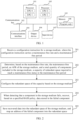
- FIG. 2 shows a storage medium management method according to an example embodiment.
- the storage medium management method is applied to the foregoing storage system.
- the method may include the following several implementation steps.
- Step 201 Receive a configuration instruction for a storage medium, where the configuration instruction carries a maintenance-free rate and a maintenance-free period.
- a core of maintenance-free is to use redundant space to prevent components from being all damaged in a life cycle. Therefore, in an actual implementation, to enable the storage medium to achieve a maintenance-free effect, a user may configure redundant space of a proper capacity in the storage medium based on an actual requirement, to use the redundant space to implement the maintenance-free effect.
- a specific implementation of configuring the redundant space of the proper capacity is described in step 201 to step 203.
- the configuration instruction may be sent by a host to the storage system. Further, the configuration instruction may be sent by the user to the storage system by using the host.
- the user may customize the maintenance-free rate and the maintenance-free period based on the actual requirement, and deliver the maintenance-free rate and the maintenance-free period to the storage system by using the configuration instruction, to configure or change a maintenance-free parameter of the storage system. If no redundant space is configured in the storage system before, delivering the configuration instruction by the user means instructing the storage system to configure the maintenance-free parameter. If redundant space is configured in the storage system before, delivering the configuration instruction by the user means instructing the storage system to change the maintenance-free parameter.
- the maintenance-free rate carried in the configuration instruction may be set to 99.999128%, and the maintenance-free period is set to 3.
- a format of the configuration instruction may be in a command form of a standard small computer system interface (Small Computer System Interface, SCSI)/a non-volatile memory express (Non Volatile Memory express, NVMe) standard, or the like, or may be in a user-defined form.
- SCSI Small Computer System Interface
- NVMe Non Volatile Memory express
- the configuration instruction may be specifically: Dis_Maintain (Control).
- Control may further include parameters such as a maintenance-free switch, the maintenance-free rate, and the maintenance-free period.
- the maintenance-free switch is used to instruct to enable or disable a maintenance-free function.
- a parameter may be set. For example, maintenance-free parameters such as the maintenance-free rate and the maintenance-free period are set.
- the maintenance-free rate and the maintenance-free period may alternatively be obtained by the storage system by querying a user-defined register.
- the maintenance-free rate and the maintenance-free period may be prestored in the register by default. In this case, when receiving the configuration instruction, the storage system queries the register for the maintenance-free rate and the maintenance-free period.
- the configuration instruction further carries a query instruction, and the query instruction is used to instruct to query for at least one of a maximum maintenance-free capability, a maintenance-free status, a maintenance-free configuration parameter, a maintenance-free determining result, an available capacity, maintenance-free time, and MTBF of the storage medium.
- the configuration instruction may be Dis_Maintain(Control, Status), where Status indicates the query instruction. Further, for a maintenance-free storage system that has been configured before, a configured maintenance-free parameter and the like may be queried for by using Status.
- the maximum maintenance-free capability refers to a maximum maintenance-free period and a maximum maintenance-free rate that can be supported by the system.
- the maximum maintenance-free capability DisMaintain_Max is a ten-year maintenance-free period, and a maintenance-free rate of eight nines is supported, before the storage system performs the following steps, it may further be determined whether the maintenance-free period and the maintenance-free rate carried in the configuration instruction exceed the maximum maintenance-free capability. If the maintenance-free period and the maintenance-free rate carried in the configuration instruction exceed the maximum maintenance-free capability, that the configuration cannot be performed is indicated; otherwise, the method proceeds to subsequent step 202.
- the maintenance-free status includes an enabled state and a disabled state. Further, in an actual application, the maintenance-free status may be defined as DisMaintain_Status.
- the maintenance-free configuration parameter refers to the maintenance-free rate and the maintenance-free period that have been set previously. Further, the maintenance-free configuration parameter may be defined as DisMaintain_Para.
- the maintenance-free determining result includes success and failure. For example, if the configuration succeeds, succeed is displayed; or if the configuration fails (for example, when the specified maintenance-free parameters exceed the maximum maintenance-free capability of the system), failed is displayed. Further, the maintenance-free determining result may be defined as DisMaintain_judge.
- the available capacity is a capacity available to the user after the maintenance-free function is enabled. Further, the available capacity may be defined as DisMaintain_Capa.
- the maintenance-free time includes a time point for enabling the maintenance-free function and a remaining maintenance-free time period. Further, the maintenance-free time may be defined as DisMaintain_Time.
- the query instruction is used to instruct to query for at least one of the maximum maintenance-free capability, the maintenance-free status, the maintenance-free configuration parameter, the maintenance-free determining result, the available capacity, the maintenance-free time, and the MTBF of the storage medium is used for description in the foregoing.
- the query instruction may alternatively be used to instruct to query for other information.
- the query instruction may alternatively be used to instruct to query for the AFR.
- the configuration instruction carries the query instruction
- the query instruction may alternatively be carried in a separate command. This is not limited in this embodiment of this application.
- Step 202 Determine, based on the maintenance-free rate, the maintenance-free period, the AFR of the storage medium, and a total quantity of components included in the storage medium, a capacity of the redundant space required to reach the maintenance-free status in the maintenance-free period.
- the storage system may determine, by using the following formula (1) based on the maintenance-free rate, the maintenance-free period, the AFR of the storage medium, and the total quantity of components included in the storage medium, the capacity of the redundant space required to reach the maintenance-free status in the maintenance-free period:
- ⁇ P ⁇ X k ⁇ represents the maintenance-free rate, in other words, represents a probability that k or less than k failures occur in n components
- n represents the total quantity of components included in the storage medium
- k represents the capacity of the redundant space
- the AFR may be obtained by querying.
- a query method of the AFR is described above, and details are not described herein again.
- the AFR may be carried in the foregoing configuration instruction.
- the AFR may alternatively be queried for by the user based on the actually used storage medium, and then entered by using the configuration instruction.
- the capacity of the redundant space required to reach the maintenance-free status in the maintenance-free period may be determined by using the foregoing formula (1).
- the storage medium is an SSD of 25 1-TB units
- a physical raw capacity of the SSD is 25 TB.
- system OP space over-provisioned by the system is 7 TB
- a physical capacity available to the user is 18 TB.
- the maintenance-free status of the SSD is entered (in other words, after the foregoing configuration instruction is received)
- the maintenance-free rate carried in the received configuration instruction is five nines and the maintenance-free period is three years
- the AFR is 0.438%. Therefore, it may be determined, by using the foregoing formula (1), that the redundant space that needs to be configured is 5 TB. In other words, five spaces of the SSD need to be configured.
- the physical capacity available to the user is reduced to 13 TB.
- the components included in the storage medium are each a storage component applied to an independent failure unit in the system.
- the components are independent of each other. If a component is damaged, other components around the component are not affected.
- the redundant space may alternatively be fixedly configured.
- the capacity of the redundant space is already fixedly preset. In this case, the foregoing calculation process does not need to be performed, and a subsequent configuration operation only needs to be performed based on the fixedly preset capacity.
- An increase in component granularity may reduce a redundancy ratio to some extent. If there are more components in the storage medium, the cost for implementing maintenance-free is lower. An example in which the AFR is 0.438% is used.
- a hard disk enclosure includes 24 disks, to achieve a three-year maintenance-free effect, it may be determined, through calculation by using the foregoing formula (1), that five redundant disks are required. If the total quantity of components increases to 240, to achieve the three-year maintenance-free effect, a quantity of redundant disks is correspondingly reduced to 13. If the total quantity of components increases further, the redundancy ratio also decreases further.
- the redundancy ratio is a ratio of a quantity of redundant components to the total quantity of components. Therefore, when designing the system (for example, setting the maintenance-free parameters), the user needs to comprehensively measure an input-to-output ratio of redundancy input, maintenance input, spare part input, and the like.
- Step 203 Configure the redundant space of the capacity based on the storage medium.
- a specific implementation of configuring the redundant space of the capacity based on the storage medium may include: determining a percentage of the capacity of the redundant space in a total capacity of the storage medium; obtaining, by division from each component included in the storage medium, a physical storage unit in a size of the percentage of the component; and determining all obtained physical storage units as the redundant space of the capacity.
- the storage system may determine that the percentage of the capacity of the redundant space in the total capacity of the storage medium is 5/25. Therefore, for each of the 25 disks included in the SSD, the storage system may obtain, by division from each disk, a physical unit in a size of 5/25 of the disk, and then determine all the obtained physical storage units as the redundant space of the capacity. In this way, the 5-TB redundant space is configured from the storage medium.
- the step of configuring the redundant space of the capacity based on the storage medium may alternatively be implemented in another manner.
- 5 TB may be selected from 18 TB available to the user as the redundant space.
- five disks are selected from the 18 disks, and the five disks are used as the redundant space.
- the redundant space may be evenly allocated in the 18 disks. This is not limited in this embodiment of this application.
- a RAID policy needs to be reconfigured based on a remaining storage medium after the redundant space configuration, and the reconfigured RAID policy is determined as the specified RAID policy.
- the RAID policy needs to be reconfigured. For example, a 21+2 erasure code, RAID 6, or 22+1 RAID 5 is configured, so that when a component of the storage medium fails later, data in the failed disk can be recovered based on the reconfigured RAID policy.
- the reconfigured RAID policy may alternatively be consistent with the original RAID policy. This is not limited in this application.
- the redundant space may be used to implement maintenance-free management. For a specific implementation, refer to the following step 204 and step 205.
- Step 204 When detecting that a component in the storage medium fails, recover, based on the specified RAID policy, data stored in the failed component.
- the storage system If it is detected that the component in the storage medium fails, the storage system enables the reconfigured specified RAID policy to recover the data, to prevent data loss. In this case, the damaged component is no longer used.
- whether the configured redundant space is sufficient to store the data in the damaged component may also be queried. If a current remaining capacity of the configured redundant space is sufficient to store the data in the damaged component, the following step 205 is performed. However, if the current remaining capacity of the configured redundant space is insufficient to store the data in the damaged component (for example, a failure rate of the storage medium increases due to some exceptions), a part of space may be borrowed from the storage medium or the OP space of the system to serve as hot backup redundancy, to ensure that the storage medium can still be maintenance-free.
- the over-provisioning OP space of the storage system is OP space that is over-provisioned from space of the storage medium for improving performance and reliability of the storage system and that is to be accessed by the system but cannot be accessed by a user
- the current remaining capacity of the redundant space is larger than or equal to the size of the data stored in the failed component, it indicates that the current remaining capacity of the configured redundant space is sufficient to store the data in the damaged component. In this case, the following step 205 may be performed. If the current remaining capacity of the redundant space is smaller than the size of the data stored in the failed component, it indicates that the current remaining capacity of the configured redundant space is insufficient to store the data in the damaged component. In this case, because the space available to the user cannot be reduced, a part of space needs to be borrowed from the OP space of the storage system to store the recovered data, and an address of the failed component is mapped into the borrowed part of space.
- Step 205 Save the recovered data into the redundant space of the storage medium, and map the address of the failed component into the redundant space, to manage the storage medium.
- the recovered data needs to be stored in the redundant space of the storage medium, so as to use the redundant space to store the data in the failed component.
- the address of the failed component is 0 GB-200 GB space of disk 1.
- the storage system maps, into the redundant space, the address of the failed component, that is, the 0 GB-200 GB space of disk 1. In this way, for a user, data originally planned to be stored in the 0 GB-200 GB space of disk 1 is actually stored in the redundant space instead of the failed component.
- the redundant space is fixedly preconfigured or is configured after the maintenance-free rate, the maintenance-free period, the annualized failure rate AFR of the storage medium, and the total quantity of components included in the storage medium are determined, the maintenance-free rate and the maintenance-free period are carried in the configuration instruction for the storage medium or obtained by querying the user-defined register, and the AFR is obtained by querying or carried in the configuration instruction.
- the storage medium management method may alternatively be applied to an all-flash (for example, a solid-state array (Solid-State Array, SSA) or an all flash array (All Flash Array, AFA)) system, a specific implementation principle is similar, and details are not described herein again.
- an all-flash for example, a solid-state array (Solid-State Array, SSA) or an all flash array (All Flash Array, AFA)
- the redundant space used to store data after failure recovery is fixedly preconfigured or is configured based on the maintenance-free rate, the maintenance-free period, the AFR of the storage medium, and the total quantity of components included in the storage medium. Therefore, even if a component in the storage medium fails, data in the failed component may be transferred to the redundant space for storage. In this way, a user does not need to manually replace the component, and maintenance-free management can be implemented on the storage medium by using the redundant space, thereby improving management efficiency.
- FIG. 3A shows a storage medium management apparatus according to an example embodiment.
- the storage medium management apparatus may be implemented by using software, hardware, or a combination thereof.
- the apparatus includes:
- the apparatus further includes:
- the first configuration module 350 is configured to:
- the apparatus further includes:
- the apparatus further includes:
- the redundant space used to store data after failure recovery is fixedly preconfigured or is configured based on the maintenance-free rate, the maintenance-free period, the AFR of the storage medium, and the total quantity of components included in the storage medium. Therefore, even if a component in the storage medium fails, data in the failed component may be transferred to the redundant space for storage. In this way, a user does not need to manually replace the component, and maintenance-free management can be implemented on the storage medium by using the redundant space, thereby improving management efficiency.
- the storage medium management apparatus provided in the foregoing embodiment implements the storage medium management method
- division of the foregoing function modules is only used as an example for description.
- the functions may be allocated to different function modules for implementation based on a requirement.
- an internal structure of a device is divided into different function modules to complete all or some functions described above.
- the storage medium management apparatus provided in the foregoing embodiment pertains to a same concept as the storage medium management method embodiment. For a specific implementation process of the storage medium management apparatus, refer to the method embodiment. Details are not described herein again.
- All or some of the foregoing embodiments may be implemented by using software, hardware, firmware, or any combination thereof.
- the embodiments may be implemented completely or partially in a form of a computer program product.
- the computer program product includes one or more computer instructions.
- the computer may be a general-purpose computer, a dedicated computer, a computer network, or another programmable apparatus.
- the computer instructions may be stored in a computer-readable storage medium or may be transmitted from a computer-readable storage medium to another computer-readable storage medium.
- the computer instructions may be transmitted from a website, computer, server, or data center to another website, computer, server, or data center in a wired (for example, a coaxial cable, an optical fiber, or a digital subscriber line (Digital Subscriber Line, DSL)) or wireless (for example, infrared, radio, or microwave) manner.
- the computer-readable storage medium may be any usable medium accessible by a computer, or a data storage device, such as a server or a data center, integrating one or more usable media.
- the usable medium may be a magnetic medium (for example, a floppy disk, a hard disk, or a magnetic tape), an optical medium (for example, a digital versatile disc (Digital Versatile Disc, DVD), a semiconductor medium (for example, a solid state drive (Solid State Disk, SSD)), or the like.
- a magnetic medium for example, a floppy disk, a hard disk, or a magnetic tape
- an optical medium for example, a digital versatile disc (Digital Versatile Disc, DVD)
- a semiconductor medium for example, a solid state drive (Solid State Disk, SSD)
- the program may be stored in a computer-readable storage medium.
- the storage medium may be a read-only memory, a magnetic disk, an optical disc, or the like.
Landscapes
- Engineering & Computer Science (AREA)
- Theoretical Computer Science (AREA)
- Quality & Reliability (AREA)
- Physics & Mathematics (AREA)
- General Engineering & Computer Science (AREA)
- General Physics & Mathematics (AREA)
- Information Retrieval, Db Structures And Fs Structures Therefor (AREA)
- Debugging And Monitoring (AREA)
Claims (13)
- Verwaltungsverfahren eines Speichersystems, wobei das Verfahren umfasst:Erhalten, durch das Speichersystem, eines wartungsfreien Parameters, wobei der wartungsfreie Parameter mindestens eines von einer wartungsfreien Rate und einer wartungsfreien Periode umfasst, wobei die wartungsfreie Rate eine Wahrscheinlichkeit ist, dass redundanter Speicherplatz nicht komplett beschädigt ist, und die wartungsfreie Periode eine Periode ist, in der ein Speichermedium des Speichersystems nicht gewartet werden muss;Bestimmen, durch das Speichersystem, einer Kapazität eines redundanten Überprovisionierungsspeicherplatzes gemäß dem wartungsfreien Parameter, wobei redundanter Überprovisionierungsspeicherplatz Speicherplatz ist, der durch ein Speichersystem zur Verwendung durch das Speichersystem überprovisioniert wird, aber für einen Benutzer nicht verfügbar ist;Konfigurieren, durch das Speichersystem, des redundantenÜberprovisionierungsspeicherplatzes des Speichersystems mit der bestimmten Kapazität.
- Verfahren nach Anspruch 1, wobei das Bestimmen des redundanten Überprovisionierungsspeicherplatzes umfasst:
Bestimmen der Kapazität des redundanten Überprovisionierungsspeicherplatzes gemäß dem wartungsfreien Parameter und einem Festplattenparameter. - Verfahren nach Anspruch 2, wobei der Festplattenparameter mindestens eine von einer annualisierten Ausfallrate, AFR, der Speichervorrichtung und einer Anzahl von Festplatten umfasst, die in der Speichervorrichtung enthalten sind.
- Verfahren nach einem der Ansprüche 1 bis 3, wobei das Erhalten des wartungsfreien Parameters umfasst:Empfangen einer Konfigurationsanweisung;Erhalten des wartungsfreien Parameters aus der Konfigurationsanweisung.
- Verfahren nach einem der Ansprüche 1 bis 4, wobei das Konfigurieren des redundanten Überprovisionierungsspeicherplatzes des Speichersystems mit der bestimmten Kapazität umfasst:Bestimmen von Festplatten, die verwendet werden, um den redundanten Überprovisionierungsspeicherplatz gemäß der bestimmten Kapazität zu konfigurieren; Bestimmen einer Kapazität jeder Festplatte, die verwendet wird, um den redundanten Überprovisionierungsspeicherplatz gemäß der bestimmten Kapazität zu konfigurieren;Konfigurieren der Kapazität jeder Festplatte, die verwendet wird, um den redundanten Überprovisionierungsspeicherplatz als den redundanten Speicherplatz zu konfigurieren.
- Verfahren nach Anspruch 2, wobei nach dem Konfigurieren des redundanten Überprovisionierungsspeicherplatzes, das Verfahren ferner umfasst Neukonfigurieren einer RAID-Richtlinie basierend auf verbleibenden Festplatten mit Ausnahme der Festplatten, die verwendet werden, um den redundanten Überprovisionierungsspeicherplatz zu konfigurieren.
- Speichersystem, das umfasst:ein Bestimmungsmodul, das konfiguriert ist, um einen wartungsfreien Parameter zu erhalten und das eine Kapazität eines redundantenÜberprovisionierungsspeicherplatzes des Speichersystems gemäß dem wartungsfreien Parameter bestimmt, wobei der wartungsfreie Parameter mindestens eines von einer wartungsfreien Rate und einer wartungsfreien Periode umfasst, wobei die wartungsfreie Rate eine Wahrscheinlichkeit ist, dass der redundante Speicherplatz nicht komplett beschädigt ist, und die wartungsfreie Periode eine Periode ist, in der ein Speichermedium des Speichersystems nicht gewartet werden muss, und wobei der redundante Überprovisionierungsspeicherplatz Speicherplatz ist, der durch ein Speichersystem zur Verwendung durch das Speichersystem überprovisioniert wird,aber für einen Benutzer nicht verfügbar ist;ein Konfigurationsmodul, das konfiguriert ist, um den redundanten Überprovisionierungsspeicherplatz des Speichersystems mit der bestimmten Kapazität zu konfigurieren.
- Speichersystem nach Anspruch 7, wobei das Bestimmungsmodul ferner konfiguriert ist zum:
Bestimmen der Kapazität des redundanten Überprovisionierungsspeicherplatzes gemäß dem wartungsfreien Parameter und einem Festplattenparameter. - Speichersystem nach Anspruch 8, wobei der Festplattenparameter mindestens eine von einer annualisierten Ausfallrate, AFR, der Speichervorrichtung und einer Anzahl von Festplatten umfasst, die in der Speichervorrichtung enthalten sind.
- Speichersystem nach einem der Ansprüche 7 bis 9, wobei das Bestimmungsmodul ferner konfiguriert ist zum:Empfangen einer Konfigurationsanweisung;Erhalten des wartungsfreien Parameters aus der Konfigurationsanweisung.
- Speichersystem nach einem der Ansprüche 7 bis 10, wobei das Konfigurationsmodul ferner konfiguriert ist zum:
Bestimmen von Festplatten, die verwendet werden, um den redundanten Überprovisionierungsspeicherplatz gemäß der bestimmten Kapazität zu konfigurieren; Bestimmen einer Kapazität jeder Festplatte, die verwendet wird, um den redundanten Überprovisionierungsspeicherplatz gemäß der bestimmten Kapazität zu konfigurieren; Konfigurieren der Kapazität jeder Festplatte, die verwendet wird, um den redundanten Überprovisionierungsspeicherplatz zu konfigurieren. - Speichersystem nach einem der Ansprüche 7 bis 11, wobei nach dem Konfigurieren des redundanten Überprovisionierungsspeicherplatzes, das Konfigurationsmodul ferner konfiguriert ist zum:
Neukonfigurieren einer RAID-Richtlinie basierend auf verbleibenden Festplatten mit Ausnahme der Festplatten, die verwendet werden, um den redundanten Überprovisionierungsspeicherplatz zu konfigurieren. - Computerlesbares Speichermedium, wobei das computerlesbare Speichermedium eine Anweisung speichert und, wenn die Anweisung durch einen Prozessor ausgeführt wird, Schritte des Verfahrens nach einem der Ansprüche 1 bis 6 implementiert werden.
Applications Claiming Priority (3)
| Application Number | Priority Date | Filing Date | Title |
|---|---|---|---|
| CN201710868918.1A CN107766180B (zh) | 2017-09-22 | 2017-09-22 | 存储介质的管理方法、装置及可读存储介质 |
| PCT/CN2018/104288 WO2019056948A1 (zh) | 2017-09-22 | 2018-09-06 | 存储介质的管理方法、装置及可读存储介质 |
| EP18857718.3A EP3667504B1 (de) | 2017-09-22 | 2018-09-06 | Speichermediumverwaltungsverfahren, vorrichtung und lesbares speichermedium |
Related Parent Applications (1)
| Application Number | Title | Priority Date | Filing Date |
|---|---|---|---|
| EP18857718.3A Division EP3667504B1 (de) | 2017-09-22 | 2018-09-06 | Speichermediumverwaltungsverfahren, vorrichtung und lesbares speichermedium |
Publications (2)
| Publication Number | Publication Date |
|---|---|
| EP4036735A1 EP4036735A1 (de) | 2022-08-03 |
| EP4036735B1 true EP4036735B1 (de) | 2024-02-14 |
Family
ID=61267421
Family Applications (2)
| Application Number | Title | Priority Date | Filing Date |
|---|---|---|---|
| EP21213020.7A Active EP4036735B1 (de) | 2017-09-22 | 2018-09-06 | Verfahren, vorrichtung sowie lesbares speichermedium |
| EP18857718.3A Active EP3667504B1 (de) | 2017-09-22 | 2018-09-06 | Speichermediumverwaltungsverfahren, vorrichtung und lesbares speichermedium |
Family Applications After (1)
| Application Number | Title | Priority Date | Filing Date |
|---|---|---|---|
| EP18857718.3A Active EP3667504B1 (de) | 2017-09-22 | 2018-09-06 | Speichermediumverwaltungsverfahren, vorrichtung und lesbares speichermedium |
Country Status (4)
| Country | Link |
|---|---|
| US (2) | US11237929B2 (de) |
| EP (2) | EP4036735B1 (de) |
| CN (2) | CN107766180B (de) |
| WO (1) | WO2019056948A1 (de) |
Families Citing this family (6)
| Publication number | Priority date | Publication date | Assignee | Title |
|---|---|---|---|---|
| CN107766180B (zh) | 2017-09-22 | 2020-08-14 | 成都华为技术有限公司 | 存储介质的管理方法、装置及可读存储介质 |
| CN108595117B (zh) * | 2018-03-29 | 2021-04-23 | 记忆科技(深圳)有限公司 | 一种动态容量调整过程中安全平滑的方法 |
| CN109445681B (zh) * | 2018-08-27 | 2021-05-11 | 华为技术有限公司 | 数据的存储方法、装置和存储系统 |
| CN109144787A (zh) * | 2018-09-03 | 2019-01-04 | 郑州云海信息技术有限公司 | 一种数据恢复方法、装置、设备及可读存储介质 |
| CN111221473B (zh) * | 2019-12-30 | 2023-06-06 | 河南创新科信息技术有限公司 | 一种存储系统介质免维护的方法 |
| CN111428280B (zh) * | 2020-06-09 | 2020-11-17 | 浙江大学 | SoC安全芯片密钥信息完整性存储及错误自修复方法 |
Family Cites Families (40)
| Publication number | Priority date | Publication date | Assignee | Title |
|---|---|---|---|---|
| US5978291A (en) * | 1998-09-30 | 1999-11-02 | International Business Machines Corporation | Sub-block redundancy replacement for a giga-bit scale DRAM |
| DE19947041C2 (de) * | 1999-09-30 | 2001-11-08 | Infineon Technologies Ag | Integrierter dynamischer Halbleiterspeicher mit redundanten Einheiten von Speicherzellen und Verfahren zur Selbstreparatur |
| US7685126B2 (en) * | 2001-08-03 | 2010-03-23 | Isilon Systems, Inc. | System and methods for providing a distributed file system utilizing metadata to track information about data stored throughout the system |
| US7263583B2 (en) * | 2004-10-05 | 2007-08-28 | International Business Machines Corporation | On demand, non-capacity based process, apparatus and computer program to determine maintenance fees for disk data storage system |
| US7603530B1 (en) * | 2005-05-05 | 2009-10-13 | Seagate Technology Llc | Methods and structure for dynamic multiple indirections in a dynamically mapped mass storage device |
| US20070067665A1 (en) * | 2005-09-19 | 2007-03-22 | Ebrahim Hashemi | Apparatus and method for providing redundant arrays storage devices |
| US7617361B2 (en) * | 2006-03-29 | 2009-11-10 | International Business Machines Corporation | Configureable redundant array of independent disks |
| US7603605B2 (en) * | 2007-01-08 | 2009-10-13 | Arm Limited | Performance control of an integrated circuit |
| JP2009043030A (ja) * | 2007-08-09 | 2009-02-26 | Hitachi Ltd | ストレージシステム |
| US8473779B2 (en) * | 2008-02-29 | 2013-06-25 | Assurance Software And Hardware Solutions, Llc | Systems and methods for error correction and detection, isolation, and recovery of faults in a fail-in-place storage array |
| CN101609420A (zh) * | 2009-07-17 | 2009-12-23 | 杭州华三通信技术有限公司 | 实现磁盘冗余阵列重建的方法和磁盘冗余阵列及其控制器 |
| US8572311B1 (en) * | 2010-01-11 | 2013-10-29 | Apple Inc. | Redundant data storage in multi-die memory systems |
| US8880843B2 (en) * | 2010-02-10 | 2014-11-04 | International Business Machines Corporation | Providing redundancy in a virtualized storage system for a computer system |
| US9727414B2 (en) * | 2010-12-01 | 2017-08-08 | Seagate Technology Llc | Fractional redundant array of silicon independent elements |
| US8601311B2 (en) * | 2010-12-14 | 2013-12-03 | Western Digital Technologies, Inc. | System and method for using over-provisioned data capacity to maintain a data redundancy scheme in a solid state memory |
| CN102097133B (zh) * | 2010-12-31 | 2012-11-21 | 中国人民解放军装备指挥技术学院 | 一种海量存储系统的可靠性测试系统及测试方法 |
| US8954787B2 (en) * | 2011-05-09 | 2015-02-10 | Cleversafe, Inc. | Establishing trust in a maintenance free storage container |
| US9021053B2 (en) * | 2011-09-02 | 2015-04-28 | Compuverde Ab | Method and device for writing data to a data storage system comprising a plurality of data storage nodes |
| CN105843557B (zh) * | 2016-03-24 | 2019-03-08 | 天津书生云科技有限公司 | 冗余存储系统、冗余存储方法和冗余存储装置 |
| US8959389B2 (en) * | 2011-11-23 | 2015-02-17 | International Business Machines Corporation | Use of a virtual drive as a hot spare for a raid group |
| JP2013125513A (ja) * | 2011-12-16 | 2013-06-24 | Samsung Electronics Co Ltd | 不揮発性半導体記憶装置及びその管理方法 |
| US8799705B2 (en) * | 2012-01-04 | 2014-08-05 | Emc Corporation | Data protection in a random access disk array |
| CN102708019B (zh) * | 2012-04-28 | 2014-12-03 | 华为技术有限公司 | 一种硬盘数据恢复方法、装置及系统 |
| CN102902602B (zh) * | 2012-09-19 | 2015-08-19 | 华为技术有限公司 | 数据热备份的方法、装置及存储系统 |
| KR102025080B1 (ko) * | 2013-01-02 | 2019-09-25 | 삼성전자 주식회사 | 스토리지 시스템 및 스토리지 시스템의 여분 공간 조절 방법 |
| US9176818B2 (en) * | 2013-03-14 | 2015-11-03 | Microsoft Technology Licensing, Llc | N-way parity for virtual disk resiliency |
| US9081753B2 (en) * | 2013-03-14 | 2015-07-14 | Microsoft Technology Licensing, Llc | Virtual disk recovery and redistribution |
| JP6318173B2 (ja) | 2013-09-24 | 2018-04-25 | 華為技術有限公司Huawei Technologies Co.,Ltd. | データマイグレーション方法、データマイグレーション装置及びストレージデバイス |
| CN103488547A (zh) * | 2013-09-24 | 2014-01-01 | 浪潮电子信息产业股份有限公司 | 一种raid组故障硬盘快速重建的方法 |
| CN106503024A (zh) * | 2015-09-08 | 2017-03-15 | 北京国双科技有限公司 | 日志信息处理方法和装置 |
| CN109358804B (zh) * | 2015-09-29 | 2022-03-29 | 华为技术有限公司 | 一种数据处理方法、装置及闪存设备 |
| US10048877B2 (en) * | 2015-12-21 | 2018-08-14 | Intel Corporation | Predictive memory maintenance |
| US9875052B2 (en) * | 2016-03-15 | 2018-01-23 | International Business Machines Corporation | Storage capacity allocation using distributed spare space |
| EP3296996B1 (de) * | 2016-06-24 | 2019-08-28 | Huawei Technologies Co., Ltd. | Verfahren zur datenverarbeitung, speichervorrichtung, festspeicher-laufwerk und speichersystem |
| TWI607303B (zh) * | 2016-10-14 | 2017-12-01 | 喬鼎資訊股份有限公司 | 具有虛擬區塊及磁碟陣列架構之資料儲存系統及其管理方法 |
| US10241877B2 (en) * | 2016-12-12 | 2019-03-26 | International Business Machines Corporation | Data storage system employing a hot spare to proactively store array data in absence of a failure or pre-failure event |
| CN106681865B (zh) * | 2017-01-16 | 2020-07-07 | 北京腾凌科技有限公司 | 业务恢复方法及装置 |
| US10915405B2 (en) * | 2017-05-26 | 2021-02-09 | Netapp, Inc. | Methods for handling storage element failures to reduce storage device failure rates and devices thereof |
| CN107766180B (zh) * | 2017-09-22 | 2020-08-14 | 成都华为技术有限公司 | 存储介质的管理方法、装置及可读存储介质 |
| CN109558333B (zh) * | 2017-09-27 | 2024-04-05 | 北京忆恒创源科技股份有限公司 | 具有可变额外存储空间的固态存储设备命名空间 |
-
2017
- 2017-09-22 CN CN201710868918.1A patent/CN107766180B/zh active Active
- 2017-09-22 CN CN202010631608.XA patent/CN111966540B/zh active Active
-
2018
- 2018-09-06 EP EP21213020.7A patent/EP4036735B1/de active Active
- 2018-09-06 EP EP18857718.3A patent/EP3667504B1/de active Active
- 2018-09-06 WO PCT/CN2018/104288 patent/WO2019056948A1/zh not_active Ceased
-
2020
- 2020-03-19 US US16/824,259 patent/US11237929B2/en active Active
-
2021
- 2021-12-08 US US17/545,203 patent/US11714733B2/en active Active
Also Published As
| Publication number | Publication date |
|---|---|
| EP3667504B1 (de) | 2021-12-22 |
| EP3667504A4 (de) | 2020-10-14 |
| CN107766180B (zh) | 2020-08-14 |
| CN111966540B (zh) | 2024-03-01 |
| CN107766180A (zh) | 2018-03-06 |
| EP4036735A1 (de) | 2022-08-03 |
| US20200218621A1 (en) | 2020-07-09 |
| EP3667504A1 (de) | 2020-06-17 |
| CN111966540A (zh) | 2020-11-20 |
| US11237929B2 (en) | 2022-02-01 |
| US20220100623A1 (en) | 2022-03-31 |
| US11714733B2 (en) | 2023-08-01 |
| WO2019056948A1 (zh) | 2019-03-28 |
Similar Documents
| Publication | Publication Date | Title |
|---|---|---|
| EP4036735B1 (de) | Verfahren, vorrichtung sowie lesbares speichermedium | |
| US10331370B2 (en) | Tuning a storage system in dependence upon workload access patterns | |
| US8838892B2 (en) | Data storage method and storage device | |
| US9262278B2 (en) | Allocation of replica-sets in a storage cluster | |
| CN114746843A (zh) | 针对已分化数据恢复配置的存储器健康跟踪 | |
| US11971771B2 (en) | Peer storage device messaging for power management | |
| US10536538B2 (en) | Secure data erasure verification in hyperscale computing systems | |
| US20220269603A1 (en) | Data storage device performance prediction based on valid fragment count | |
| US11921588B2 (en) | System and method for data protection during power loss of a storage system | |
| US11126486B2 (en) | Prediction of power shutdown and outage incidents | |
| US11137918B1 (en) | Administration of control information in a storage system | |
| US20230153206A1 (en) | Selective rebuild of interrupted devices in data storage device arrays | |
| WO2022252063A1 (zh) | 数据存取方法、存储控制器和存储设备 | |
| US11467942B2 (en) | Predictive performance indicator for storage devices | |
| US10394673B2 (en) | Method and system for hardware accelerated copyback | |
| US20240303114A1 (en) | Dynamic allocation of capacity to namespaces in a data storage device | |
| US20170123657A1 (en) | Systems and methods for back up in scale-out storage area network | |
| US20210255983A1 (en) | System and method for dynamically configuring storage mapping | |
| US20230342088A1 (en) | Hybrid solid-state drive | |
| CN113934360A (zh) | 多存储设备生命周期管理系统 | |
| US10656843B2 (en) | Systems and methods for wear levelling in a storage array | |
| EP4528515A1 (de) | Verfahren und system zur medienfehlerbehebung | |
| US20250390426A1 (en) | Delayed Parity Write for Redundant Storage Across Namespaces in Data Storage Devices | |
| US20230004301A1 (en) | Space-efficient storage of system-monitoring data | |
| CN121560238A (zh) | 一种存储单元逻辑阵列配置方法、电子设备及系统 |
Legal Events
| Date | Code | Title | Description |
|---|---|---|---|
| PUAI | Public reference made under article 153(3) epc to a published international application that has entered the european phase |
Free format text: ORIGINAL CODE: 0009012 |
|
| STAA | Information on the status of an ep patent application or granted ep patent |
Free format text: STATUS: REQUEST FOR EXAMINATION WAS MADE |
|
| 17P | Request for examination filed |
Effective date: 20211208 |
|
| AC | Divisional application: reference to earlier application |
Ref document number: 3667504 Country of ref document: EP Kind code of ref document: P |
|
| AK | Designated contracting states |
Kind code of ref document: A1 Designated state(s): AL AT BE BG CH CY CZ DE DK EE ES FI FR GB GR HR HU IE IS IT LI LT LU LV MC MK MT NL NO PL PT RO RS SE SI SK SM TR |
|
| RIN1 | Information on inventor provided before grant (corrected) |
Inventor name: ZHOU, MENG Inventor name: ZHOU, JIANHUA |
|
| GRAP | Despatch of communication of intention to grant a patent |
Free format text: ORIGINAL CODE: EPIDOSNIGR1 |
|
| STAA | Information on the status of an ep patent application or granted ep patent |
Free format text: STATUS: GRANT OF PATENT IS INTENDED |
|
| INTG | Intention to grant announced |
Effective date: 20231017 |
|
| GRAS | Grant fee paid |
Free format text: ORIGINAL CODE: EPIDOSNIGR3 |
|
| GRAA | (expected) grant |
Free format text: ORIGINAL CODE: 0009210 |
|
| STAA | Information on the status of an ep patent application or granted ep patent |
Free format text: STATUS: THE PATENT HAS BEEN GRANTED |
|
| AC | Divisional application: reference to earlier application |
Ref document number: 3667504 Country of ref document: EP Kind code of ref document: P |
|
| AK | Designated contracting states |
Kind code of ref document: B1 Designated state(s): AL AT BE BG CH CY CZ DE DK EE ES FI FR GB GR HR HU IE IS IT LI LT LU LV MC MK MT NL NO PL PT RO RS SE SI SK SM TR |
|
| REG | Reference to a national code |
Ref country code: GB Ref legal event code: FG4D |
|
| REG | Reference to a national code |
Ref country code: CH Ref legal event code: EP |
|
| REG | Reference to a national code |
Ref country code: DE Ref legal event code: R096 Ref document number: 602018065425 Country of ref document: DE |
|
| REG | Reference to a national code |
Ref country code: IE Ref legal event code: FG4D |
|
| REG | Reference to a national code |
Ref country code: LT Ref legal event code: MG9D |
|
| REG | Reference to a national code |
Ref country code: NL Ref legal event code: MP Effective date: 20240214 |
|
| PG25 | Lapsed in a contracting state [announced via postgrant information from national office to epo] |
Ref country code: IS Free format text: LAPSE BECAUSE OF FAILURE TO SUBMIT A TRANSLATION OF THE DESCRIPTION OR TO PAY THE FEE WITHIN THE PRESCRIBED TIME-LIMIT Effective date: 20240614 |
|
| PG25 | Lapsed in a contracting state [announced via postgrant information from national office to epo] |
Ref country code: LT Free format text: LAPSE BECAUSE OF FAILURE TO SUBMIT A TRANSLATION OF THE DESCRIPTION OR TO PAY THE FEE WITHIN THE PRESCRIBED TIME-LIMIT Effective date: 20240214 |
|
| PG25 | Lapsed in a contracting state [announced via postgrant information from national office to epo] |
Ref country code: GR Free format text: LAPSE BECAUSE OF FAILURE TO SUBMIT A TRANSLATION OF THE DESCRIPTION OR TO PAY THE FEE WITHIN THE PRESCRIBED TIME-LIMIT Effective date: 20240515 |
|
| REG | Reference to a national code |
Ref country code: AT Ref legal event code: MK05 Ref document number: 1657628 Country of ref document: AT Kind code of ref document: T Effective date: 20240214 |
|
| PG25 | Lapsed in a contracting state [announced via postgrant information from national office to epo] |
Ref country code: HR Free format text: LAPSE BECAUSE OF FAILURE TO SUBMIT A TRANSLATION OF THE DESCRIPTION OR TO PAY THE FEE WITHIN THE PRESCRIBED TIME-LIMIT Effective date: 20240214 Ref country code: RS Free format text: LAPSE BECAUSE OF FAILURE TO SUBMIT A TRANSLATION OF THE DESCRIPTION OR TO PAY THE FEE WITHIN THE PRESCRIBED TIME-LIMIT Effective date: 20240514 Ref country code: NL Free format text: LAPSE BECAUSE OF FAILURE TO SUBMIT A TRANSLATION OF THE DESCRIPTION OR TO PAY THE FEE WITHIN THE PRESCRIBED TIME-LIMIT Effective date: 20240214 |
|
| PG25 | Lapsed in a contracting state [announced via postgrant information from national office to epo] |
Ref country code: ES Free format text: LAPSE BECAUSE OF FAILURE TO SUBMIT A TRANSLATION OF THE DESCRIPTION OR TO PAY THE FEE WITHIN THE PRESCRIBED TIME-LIMIT Effective date: 20240214 |
|
| PG25 | Lapsed in a contracting state [announced via postgrant information from national office to epo] |
Ref country code: AT Free format text: LAPSE BECAUSE OF FAILURE TO SUBMIT A TRANSLATION OF THE DESCRIPTION OR TO PAY THE FEE WITHIN THE PRESCRIBED TIME-LIMIT Effective date: 20240214 |
|
| PG25 | Lapsed in a contracting state [announced via postgrant information from national office to epo] |
Ref country code: RS Free format text: LAPSE BECAUSE OF FAILURE TO SUBMIT A TRANSLATION OF THE DESCRIPTION OR TO PAY THE FEE WITHIN THE PRESCRIBED TIME-LIMIT Effective date: 20240514 Ref country code: NO Free format text: LAPSE BECAUSE OF FAILURE TO SUBMIT A TRANSLATION OF THE DESCRIPTION OR TO PAY THE FEE WITHIN THE PRESCRIBED TIME-LIMIT Effective date: 20240514 Ref country code: NL Free format text: LAPSE BECAUSE OF FAILURE TO SUBMIT A TRANSLATION OF THE DESCRIPTION OR TO PAY THE FEE WITHIN THE PRESCRIBED TIME-LIMIT Effective date: 20240214 Ref country code: LT Free format text: LAPSE BECAUSE OF FAILURE TO SUBMIT A TRANSLATION OF THE DESCRIPTION OR TO PAY THE FEE WITHIN THE PRESCRIBED TIME-LIMIT Effective date: 20240214 Ref country code: IS Free format text: LAPSE BECAUSE OF FAILURE TO SUBMIT A TRANSLATION OF THE DESCRIPTION OR TO PAY THE FEE WITHIN THE PRESCRIBED TIME-LIMIT Effective date: 20240614 Ref country code: HR Free format text: LAPSE BECAUSE OF FAILURE TO SUBMIT A TRANSLATION OF THE DESCRIPTION OR TO PAY THE FEE WITHIN THE PRESCRIBED TIME-LIMIT Effective date: 20240214 Ref country code: GR Free format text: LAPSE BECAUSE OF FAILURE TO SUBMIT A TRANSLATION OF THE DESCRIPTION OR TO PAY THE FEE WITHIN THE PRESCRIBED TIME-LIMIT Effective date: 20240515 Ref country code: FI Free format text: LAPSE BECAUSE OF FAILURE TO SUBMIT A TRANSLATION OF THE DESCRIPTION OR TO PAY THE FEE WITHIN THE PRESCRIBED TIME-LIMIT Effective date: 20240214 Ref country code: ES Free format text: LAPSE BECAUSE OF FAILURE TO SUBMIT A TRANSLATION OF THE DESCRIPTION OR TO PAY THE FEE WITHIN THE PRESCRIBED TIME-LIMIT Effective date: 20240214 Ref country code: BG Free format text: LAPSE BECAUSE OF FAILURE TO SUBMIT A TRANSLATION OF THE DESCRIPTION OR TO PAY THE FEE WITHIN THE PRESCRIBED TIME-LIMIT Effective date: 20240214 Ref country code: AT Free format text: LAPSE BECAUSE OF FAILURE TO SUBMIT A TRANSLATION OF THE DESCRIPTION OR TO PAY THE FEE WITHIN THE PRESCRIBED TIME-LIMIT Effective date: 20240214 |
|
| PG25 | Lapsed in a contracting state [announced via postgrant information from national office to epo] |
Ref country code: PL Free format text: LAPSE BECAUSE OF FAILURE TO SUBMIT A TRANSLATION OF THE DESCRIPTION OR TO PAY THE FEE WITHIN THE PRESCRIBED TIME-LIMIT Effective date: 20240214 Ref country code: PT Free format text: LAPSE BECAUSE OF FAILURE TO SUBMIT A TRANSLATION OF THE DESCRIPTION OR TO PAY THE FEE WITHIN THE PRESCRIBED TIME-LIMIT Effective date: 20240614 |
|
| PG25 | Lapsed in a contracting state [announced via postgrant information from national office to epo] |
Ref country code: SE Free format text: LAPSE BECAUSE OF FAILURE TO SUBMIT A TRANSLATION OF THE DESCRIPTION OR TO PAY THE FEE WITHIN THE PRESCRIBED TIME-LIMIT Effective date: 20240214 Ref country code: PT Free format text: LAPSE BECAUSE OF FAILURE TO SUBMIT A TRANSLATION OF THE DESCRIPTION OR TO PAY THE FEE WITHIN THE PRESCRIBED TIME-LIMIT Effective date: 20240614 Ref country code: PL Free format text: LAPSE BECAUSE OF FAILURE TO SUBMIT A TRANSLATION OF THE DESCRIPTION OR TO PAY THE FEE WITHIN THE PRESCRIBED TIME-LIMIT Effective date: 20240214 Ref country code: LV Free format text: LAPSE BECAUSE OF FAILURE TO SUBMIT A TRANSLATION OF THE DESCRIPTION OR TO PAY THE FEE WITHIN THE PRESCRIBED TIME-LIMIT Effective date: 20240214 |
|
| PG25 | Lapsed in a contracting state [announced via postgrant information from national office to epo] |
Ref country code: DK Free format text: LAPSE BECAUSE OF FAILURE TO SUBMIT A TRANSLATION OF THE DESCRIPTION OR TO PAY THE FEE WITHIN THE PRESCRIBED TIME-LIMIT Effective date: 20240214 |
|
| PG25 | Lapsed in a contracting state [announced via postgrant information from national office to epo] |
Ref country code: SM Free format text: LAPSE BECAUSE OF FAILURE TO SUBMIT A TRANSLATION OF THE DESCRIPTION OR TO PAY THE FEE WITHIN THE PRESCRIBED TIME-LIMIT Effective date: 20240214 |
|
| PG25 | Lapsed in a contracting state [announced via postgrant information from national office to epo] |
Ref country code: CZ Free format text: LAPSE BECAUSE OF FAILURE TO SUBMIT A TRANSLATION OF THE DESCRIPTION OR TO PAY THE FEE WITHIN THE PRESCRIBED TIME-LIMIT Effective date: 20240214 Ref country code: EE Free format text: LAPSE BECAUSE OF FAILURE TO SUBMIT A TRANSLATION OF THE DESCRIPTION OR TO PAY THE FEE WITHIN THE PRESCRIBED TIME-LIMIT Effective date: 20240214 |
|
| PG25 | Lapsed in a contracting state [announced via postgrant information from national office to epo] |
Ref country code: SK Free format text: LAPSE BECAUSE OF FAILURE TO SUBMIT A TRANSLATION OF THE DESCRIPTION OR TO PAY THE FEE WITHIN THE PRESCRIBED TIME-LIMIT Effective date: 20240214 |
|
| PG25 | Lapsed in a contracting state [announced via postgrant information from national office to epo] |
Ref country code: SM Free format text: LAPSE BECAUSE OF FAILURE TO SUBMIT A TRANSLATION OF THE DESCRIPTION OR TO PAY THE FEE WITHIN THE PRESCRIBED TIME-LIMIT Effective date: 20240214 Ref country code: SK Free format text: LAPSE BECAUSE OF FAILURE TO SUBMIT A TRANSLATION OF THE DESCRIPTION OR TO PAY THE FEE WITHIN THE PRESCRIBED TIME-LIMIT Effective date: 20240214 Ref country code: RO Free format text: LAPSE BECAUSE OF FAILURE TO SUBMIT A TRANSLATION OF THE DESCRIPTION OR TO PAY THE FEE WITHIN THE PRESCRIBED TIME-LIMIT Effective date: 20240214 Ref country code: EE Free format text: LAPSE BECAUSE OF FAILURE TO SUBMIT A TRANSLATION OF THE DESCRIPTION OR TO PAY THE FEE WITHIN THE PRESCRIBED TIME-LIMIT Effective date: 20240214 Ref country code: DK Free format text: LAPSE BECAUSE OF FAILURE TO SUBMIT A TRANSLATION OF THE DESCRIPTION OR TO PAY THE FEE WITHIN THE PRESCRIBED TIME-LIMIT Effective date: 20240214 Ref country code: CZ Free format text: LAPSE BECAUSE OF FAILURE TO SUBMIT A TRANSLATION OF THE DESCRIPTION OR TO PAY THE FEE WITHIN THE PRESCRIBED TIME-LIMIT Effective date: 20240214 |
|
| REG | Reference to a national code |
Ref country code: DE Ref legal event code: R097 Ref document number: 602018065425 Country of ref document: DE |
|
| PG25 | Lapsed in a contracting state [announced via postgrant information from national office to epo] |
Ref country code: IT Free format text: LAPSE BECAUSE OF FAILURE TO SUBMIT A TRANSLATION OF THE DESCRIPTION OR TO PAY THE FEE WITHIN THE PRESCRIBED TIME-LIMIT Effective date: 20240214 |
|
| PLBE | No opposition filed within time limit |
Free format text: ORIGINAL CODE: 0009261 |
|
| STAA | Information on the status of an ep patent application or granted ep patent |
Free format text: STATUS: NO OPPOSITION FILED WITHIN TIME LIMIT |
|
| PG25 | Lapsed in a contracting state [announced via postgrant information from national office to epo] |
Ref country code: IT Free format text: LAPSE BECAUSE OF FAILURE TO SUBMIT A TRANSLATION OF THE DESCRIPTION OR TO PAY THE FEE WITHIN THE PRESCRIBED TIME-LIMIT Effective date: 20240214 |
|
| 26N | No opposition filed |
Effective date: 20241115 |
|
| PG25 | Lapsed in a contracting state [announced via postgrant information from national office to epo] |
Ref country code: MC Free format text: LAPSE BECAUSE OF FAILURE TO SUBMIT A TRANSLATION OF THE DESCRIPTION OR TO PAY THE FEE WITHIN THE PRESCRIBED TIME-LIMIT Effective date: 20240214 Ref country code: SI Free format text: LAPSE BECAUSE OF FAILURE TO SUBMIT A TRANSLATION OF THE DESCRIPTION OR TO PAY THE FEE WITHIN THE PRESCRIBED TIME-LIMIT Effective date: 20240214 |
|
| REG | Reference to a national code |
Ref country code: CH Ref legal event code: PL |
|
| PG25 | Lapsed in a contracting state [announced via postgrant information from national office to epo] |
Ref country code: LU Free format text: LAPSE BECAUSE OF NON-PAYMENT OF DUE FEES Effective date: 20240906 |
|
| GBPC | Gb: european patent ceased through non-payment of renewal fee |
Effective date: 20240906 |
|
| PG25 | Lapsed in a contracting state [announced via postgrant information from national office to epo] |
Ref country code: GB Free format text: LAPSE BECAUSE OF NON-PAYMENT OF DUE FEES Effective date: 20240906 |
|
| REG | Reference to a national code |
Ref country code: BE Ref legal event code: MM Effective date: 20240930 |
|
| PG25 | Lapsed in a contracting state [announced via postgrant information from national office to epo] |
Ref country code: BE Free format text: LAPSE BECAUSE OF NON-PAYMENT OF DUE FEES Effective date: 20240930 |
|
| PG25 | Lapsed in a contracting state [announced via postgrant information from national office to epo] |
Ref country code: FR Free format text: LAPSE BECAUSE OF NON-PAYMENT OF DUE FEES Effective date: 20240930 |
|
| PG25 | Lapsed in a contracting state [announced via postgrant information from national office to epo] |
Ref country code: CH Free format text: LAPSE BECAUSE OF NON-PAYMENT OF DUE FEES Effective date: 20240930 |
|
| PG25 | Lapsed in a contracting state [announced via postgrant information from national office to epo] |
Ref country code: IE Free format text: LAPSE BECAUSE OF NON-PAYMENT OF DUE FEES Effective date: 20240906 |
|
| PGFP | Annual fee paid to national office [announced via postgrant information from national office to epo] |
Ref country code: DE Payment date: 20250730 Year of fee payment: 8 |
|
| PG25 | Lapsed in a contracting state [announced via postgrant information from national office to epo] |
Ref country code: CY Free format text: LAPSE BECAUSE OF FAILURE TO SUBMIT A TRANSLATION OF THE DESCRIPTION OR TO PAY THE FEE WITHIN THE PRESCRIBED TIME-LIMIT; INVALID AB INITIO Effective date: 20180906 |
|
| PG25 | Lapsed in a contracting state [announced via postgrant information from national office to epo] |
Ref country code: HU Free format text: LAPSE BECAUSE OF FAILURE TO SUBMIT A TRANSLATION OF THE DESCRIPTION OR TO PAY THE FEE WITHIN THE PRESCRIBED TIME-LIMIT; INVALID AB INITIO Effective date: 20180906 |