EP4036873B1 - Dispositif de commande d'enregistrement, procédé de commande d'enregistrement et programme de commande d'enregistrement - Google Patents
Dispositif de commande d'enregistrement, procédé de commande d'enregistrement et programme de commande d'enregistrement Download PDFInfo
- Publication number
- EP4036873B1 EP4036873B1 EP20870198.7A EP20870198A EP4036873B1 EP 4036873 B1 EP4036873 B1 EP 4036873B1 EP 20870198 A EP20870198 A EP 20870198A EP 4036873 B1 EP4036873 B1 EP 4036873B1
- Authority
- EP
- European Patent Office
- Prior art keywords
- event
- marking
- detection
- time
- video data
- Prior art date
- Legal status (The legal status is an assumption and is not a legal conclusion. Google has not performed a legal analysis and makes no representation as to the accuracy of the status listed.)
- Active
Links
Images

Classifications
-
- H—ELECTRICITY
- H04—ELECTRIC COMMUNICATION TECHNIQUE
- H04N—PICTORIAL COMMUNICATION, e.g. TELEVISION
- H04N5/00—Details of television systems
- H04N5/76—Television signal recording
- H04N5/765—Interface circuits between an apparatus for recording and another apparatus
-
- G—PHYSICS
- G06—COMPUTING OR CALCULATING; COUNTING
- G06V—IMAGE OR VIDEO RECOGNITION OR UNDERSTANDING
- G06V20/00—Scenes; Scene-specific elements
- G06V20/40—Scenes; Scene-specific elements in video content
- G06V20/44—Event detection
-
- G—PHYSICS
- G07—CHECKING-DEVICES
- G07C—TIME OR ATTENDANCE REGISTERS; REGISTERING OR INDICATING THE WORKING OF MACHINES; GENERATING RANDOM NUMBERS; VOTING OR LOTTERY APPARATUS; ARRANGEMENTS, SYSTEMS OR APPARATUS FOR CHECKING NOT PROVIDED FOR ELSEWHERE
- G07C5/00—Registering or indicating the working of vehicles
- G07C5/08—Registering or indicating performance data other than driving, working, idle, or waiting time, with or without registering driving, working, idle or waiting time
- G07C5/0841—Registering performance data
- G07C5/085—Registering performance data using electronic data carriers
- G07C5/0866—Registering performance data using electronic data carriers the electronic data carrier being a digital video recorder in combination with video camera
-
- G—PHYSICS
- G08—SIGNALLING
- G08G—TRAFFIC CONTROL SYSTEMS
- G08G1/00—Traffic control systems for road vehicles
- G08G1/01—Detecting movement of traffic to be counted or controlled
- G08G1/0104—Measuring and analyzing of parameters relative to traffic conditions
-
- G—PHYSICS
- G08—SIGNALLING
- G08G—TRAFFIC CONTROL SYSTEMS
- G08G1/00—Traffic control systems for road vehicles
- G08G1/20—Monitoring the location of vehicles belonging to a group, e.g. fleet of vehicles, countable or determined number of vehicles
- G08G1/205—Indicating the location of the monitored vehicles as destination, e.g. accidents, stolen, rental
-
- H—ELECTRICITY
- H04—ELECTRIC COMMUNICATION TECHNIQUE
- H04N—PICTORIAL COMMUNICATION, e.g. TELEVISION
- H04N5/00—Details of television systems
- H04N5/76—Television signal recording
-
- H—ELECTRICITY
- H04—ELECTRIC COMMUNICATION TECHNIQUE
- H04N—PICTORIAL COMMUNICATION, e.g. TELEVISION
- H04N5/00—Details of television systems
- H04N5/76—Television signal recording
- H04N5/765—Interface circuits between an apparatus for recording and another apparatus
- H04N5/77—Interface circuits between an apparatus for recording and another apparatus between a recording apparatus and a television camera
-
- H—ELECTRICITY
- H04—ELECTRIC COMMUNICATION TECHNIQUE
- H04N—PICTORIAL COMMUNICATION, e.g. TELEVISION
- H04N5/00—Details of television systems
- H04N5/76—Television signal recording
- H04N5/91—Television signal processing therefor
- H04N5/92—Transformation of the television signal for recording, e.g. modulation, frequency changing; Inverse transformation for playback
-
- H—ELECTRICITY
- H04—ELECTRIC COMMUNICATION TECHNIQUE
- H04N—PICTORIAL COMMUNICATION, e.g. TELEVISION
- H04N7/00—Television systems
- H04N7/18—Closed-circuit television [CCTV] systems, i.e. systems in which the video signal is not broadcast
-
- H—ELECTRICITY
- H04—ELECTRIC COMMUNICATION TECHNIQUE
- H04N—PICTORIAL COMMUNICATION, e.g. TELEVISION
- H04N7/00—Television systems
- H04N7/18—Closed-circuit television [CCTV] systems, i.e. systems in which the video signal is not broadcast
- H04N7/183—Closed-circuit television [CCTV] systems, i.e. systems in which the video signal is not broadcast for receiving images from a single remote source
-
- H—ELECTRICITY
- H04—ELECTRIC COMMUNICATION TECHNIQUE
- H04N—PICTORIAL COMMUNICATION, e.g. TELEVISION
- H04N9/00—Details of colour television systems
- H04N9/79—Processing of colour television signals in connection with recording
- H04N9/80—Transformation of the television signal for recording, e.g. modulation, frequency changing; Inverse transformation for playback
- H04N9/82—Transformation of the television signal for recording, e.g. modulation, frequency changing; Inverse transformation for playback the individual colour picture signal components being recorded simultaneously only
- H04N9/8205—Transformation of the television signal for recording, e.g. modulation, frequency changing; Inverse transformation for playback the individual colour picture signal components being recorded simultaneously only involving the multiplexing of an additional signal and the colour video signal
-
- G—PHYSICS
- G07—CHECKING-DEVICES
- G07C—TIME OR ATTENDANCE REGISTERS; REGISTERING OR INDICATING THE WORKING OF MACHINES; GENERATING RANDOM NUMBERS; VOTING OR LOTTERY APPARATUS; ARRANGEMENTS, SYSTEMS OR APPARATUS FOR CHECKING NOT PROVIDED FOR ELSEWHERE
- G07C5/00—Registering or indicating the working of vehicles
- G07C5/02—Registering or indicating driving, working, idle, or waiting time only
Definitions
- the present invention relates to a recording control apparatus, a recording control method, and a recording control program configured to record information such as a video capturing a scene around a vehicle.
- JP 201 9117518 A discloses a recording control device which includes: a video data acquisition part for acquiring video data obtained by photographing the surroundings of a vehicle; an event detection part for detecting the occurrence of a predetermined event for the vehicle; a change point determination part for determining whether or not the vehicle has passed a change point of a traveling path on the basis of current position information of the vehicle; and a recording control part for recording, as an event recording file, video data including a first period from the passing time of the change point that passed more than a first time before a detection time of an event to the detection time of the event when the event detection part detects the occurrence of the event.
- US 2018 357484 A discloses a video processing device and video processing method.
- US 2018 007323 A discloses an apparatus and method for recording data associated with a vehicle.
- a recording control apparatus according to claim 1, a recording control method according to claim 3, and a recording control program according to claim 4 is provided.
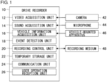
- Fig. 1 is a block diagram schematically showing functional features of a drive recorder 10.
- the functional blocks depicted are implemented in hardware such as devices or mechanical components such as a CPU or a memory of a computer, and in software such as a computer program.
- Fig. 1 depicts functional blocks implemented by the cooperation of these elements. Therefore, it will be understood by those skilled in the art that these functional blocks may be implemented in a variety of manners by a combination of hardware and software.
- the drive recorder 10 includes a video acquisition unit 12, a sound acquisition unit 14, a vehicle information acquisition unit 16, an event detection unit 18, a recording control unit 20, a temporary storage unit 22, a communication unit 24, and a user operation reception unit 26.
- the video acquisition unit 12 may be configured as a part of the vehicle information acquisition unit 16, or the video acquisition unit 12 may be included in the vehicle information acquisition unit 16.
- the drive recorder 10 is mounted on a vehicle.
- the communication unit 24 exchanges information with an external device by communicating therewith by wireless connection.
- the user operation reception unit 26 receives a user operation input from a user.
- the drive recorder 10 may further include a monitor unit that displays a video taken and a speaker unit that outputs recorded sound.
- the video acquisition unit 12 acquires video data taken by a camera 42 provided in the vehicle.
- the camera 42 is configured to image a scene around the vehicle.
- the camera 42 is configured to image a scene in front of the vehicle.
- the camera 42 may be configured to image only a scene outside the vehicle or image scenes both outside and inside the vehicle.
- a plurality of cameras may be mounted in a vehicle.
- the plurality of cameras may image scenes in front of, behind, to the side of, and inside the vehicle, respectively.
- the camera 42 may be configured as a full-circumference camera capable of capturing a scene 360° around or a plurality of cameras capturing scenes in front and behind.
- the camera 42 may be built in the drive recorder 10 or separate from the drive recorder 10.
- the video acquisition unit 12 may acquire, as vehicle information related to the driving of the vehicle, an image taken by the camera 42.
- the video acquisition unit 12 may be regarded as a part of the vehicle information acquisition unit 16.
- the sound acquisition unit 14 acquires sound data acquired by a microphone 44 provided in the vehicle.
- the microphone 44 is configured to collect sound from inside and outside the vehicle.
- the microphone 44 may be built in the drive recorder 10, separate from the drive recorder 10, or integrated with the camera 42.
- the sound acquisition unit 14 may acquire, as vehicle information related to the driving of the vehicle, sound by using the microphone 44.
- the sound acquisition unit 14 may be regarded as a part of the vehicle information acquisition unit 16.
- the vehicle information acquisition unit 16 acquires vehicle information related to the driving of the vehicle from a vehicle-mounted apparatus 46 provided in the vehicle.
- vehicle-mounted apparatus 46 include, but are not limited to, a vehicle speed sensor, steering angle sensor, accelerator position sensor, brake position sensor, acceleration sensor, gyro sensor, radar sensor, Light Detection and Ranging (LiDAR), position information sensor (e.g., GNSS; Global Navigation Satellite System), passenger seat sensor, etc.
- the vehicle information acquisition unit 16 may acquire vehicle information via various electronic control units (ECU) or may acquire vehicle information via a navigation apparatus.
- the vehicle information acquisition unit 16 may acquire information detected various sensors such as an acceleration sensor, gyro sensor, and position information sensor built in the terminal of a user such as a cell phone.
- the vehicle information acquisition unit 16 may acquire information related to the driving of the vehicle from a sensor built in the drive recorder 10. For example, sensors like an acceleration sensor, a position information sensor, etc. may be built in the drive recorder 10.
- the camera 42 or the microphone 44 may be regarded as one of vehicle-mounted apparatuses, and the vehicle information acquisition unit 16 may be configured to include the video acquisition unit 12 or the sound acquisition unit 14.
- the vehicle information acquisition unit 16 acquires information related to the condition of the vehicle, information related to the manipulation of the vehicle, information related to the speed of the vehicle, information related to the position of the vehicle, information related to an obstacle around the vehicle, information related to the operating condition of the driving assistance function of the vehicle etc. from the vehicle-mounted apparatus 46.
- the vehicle information acquisition unit 16 may acquire, as information related to the condition of the vehicle, information indicating whether the door or the window is open or closed.
- the vehicle information acquisition unit 16 may acquire, as information related to the manipulation of the vehicle, information indicating whether a user manipulation to request the door or the window to be opened or closed.
- the vehicle information acquisition unit 16 may acquire, as information related to an obstacle around the vehicle, information indicating whether a further vehicle is located within a certain range around the vehicle or whether a pedestrian, a bicycle, an obstacle such as a fallen object or a building is located on the traffic lane on which the vehicle is traveling.
- the vehicle information acquisition unit 16 may acquire information indicating whether a passenger is in the vehicle.
- the vehicle information acquisition unit 16 may acquire, as information related to the operating condition of the driving assistance function of the vehicle, information related to on/off of the automatic driving function or remote control function or information related to whether a particular driving assistance function is in operation.
- the driving assistance function is exemplified by, but is not limited to, adaptive cruise control (ACC) or lane keeping assistance system (LKAS).
- the event detection unit 18 detects occurrence of various predefined events, based on video data acquired by the video acquisition unit 12, sound data acquired by the sound acquisition unit 14, and vehicle information acquired by the vehicle information acquisition unit 16.
- a trigger event and a marking event are predefined as events that the event detection unit 18 is capable of detecting.
- a trigger event is a save-triggering event that triggers saving of video data as overwrite-disabled data in the event of its occurrence or detection.
- the event detection unit 18 detects, as a trigger event, occurrence of an accident such as collision, contact, overturn, and fall of a vehicle or of a trouble such as rude conduct and dangerous driving by the driver of a vehicle around.
- the event detection unit 18 may refer to video data acquired by the camera 42 or sound data acquired by the microphone 44 to detect occurrence of an accident or a trouble by image recognition or sound recognition based on a predetermined recognition pattern.
- the event detection unit 18 may refer to information such as traveling speed and acceleration of the vehicle and information related to manipulation of accelerator, brake, steering, etc.
- the event detection unit 18 may detect the occurrence of a trigger event by recognizing an abrupt change in vehicle behavior based on a predetermined threshold value or a predetermined recognition pattern for recognizing a condition in which the likelihood of an accident or a trouble is high.
- the event detection unit 18 may refer to video data of the camera 42, information from a radar sensor of the vehicle, etc. to detect the occurrence of a trigger event by recognizing approach to the vehicle in front, approach to an object around the vehicle, deviation from a lane being traveled, etc., based on a predetermined recognition pattern.
- the event detection unit 18 may also detect the occurrence of a trigger event when the user operation reception unit 26 receives pressing of a save start button provided in the drive recorder 10 or an audio command designating start of saving.
- a marking event is an event not triggering saving that could have certain ex-post relevance to a serious incident such as an accident and a trouble that may occur subsequent to the marking event.
- a marking event does not trigger saving on its own but is an event for which it is defined that the timing of detection thereof should be recorded.
- Individual standby periods are defined for respective types of the marking event.
- the standby periods defined for each marking event include a variable first standby period adjusted to suit the overall capacity or available capacity of a recording medium 48 and a fixed second standby period defined separately from the first standby period.
- the first standby period is a variable period for which the upper limit is the duration of the second standby period. Details of the standby period will be described later.
- a marking event is an event that can be said to be normally irrelevant to an accident or a trouble.
- a marking event may be an event such as abnormal noise, opening or closing of a door or a window, flickering of light, change in a passenger, driver's action other than steering, up and down movement of a vehicle, behavior of a vehicle around, and weather change.
- "Abnormal noise” as a marking event is sound inside and outside the vehicle acquired by the microphone 44 and recognized based on a predetermined recognition pattern.
- "abnormal noise” may be sound exceeding a predetermined sound level, sound for which a rate of increase of sound volume exceeds a predetermined value, sound within a predetermined frequency range, or sound of a cell phone.
- "Opening or closing of a door or a window” as a marking event is detected based on information that the vehicle information acquisition unit 16 acquires from the vehicle-mounted apparatus 46 as indicating the open or closed condition of a door or a window or information indicating that a user operation requesting opening or closing of a door or a window is provided.
- “Flickering of light” as a marking event is detected from, for example, image data, based on a predetermined recognition pattern.
- "Change in a passenger" as a marking event is a large change in the line of sight or posture of the driver or a passenger and is detected from the image data, based on a predetermined recognition pattern.
- change in the line of sight is a change in which the driver or a passenger witnesses an accident or sudden pedestrian crossing occurring outside the vehicle and suddenly moves the line of sight in the direction of occurrence.
- Change in posture is an action different from an ordinary driving action such as an action of picking up an article dropped on the floor.
- Driver's action other than steering as a marking event may be a driving action other than steering such as manipulation of a direction indicator, a shift lever, and a hand brake or may be an action other than a driving action such as manipulation of an apparatus such as a navigation apparatus, audio apparatus, and cell phone, These actions may be detected by referring to information acquired from the vehicle-mounted apparatus 46 and related to an action to control the vehicle or may be detected from the video data capturing the interior of the vehicle, based on a predetermined recognition pattern. "Up and down movement of a vehicle” may be up and down movement caused by a step encountered when the vehicle enters or leaves a parking lot and may be detected based on vehicle information from an acceleration sensor or from image data, based on a predetermined threshold value or recognition pattern.
- a marking event detected is an event that lasts a relatively short period of time
- the point of time when the marking event was first detected may be defined as the "point of time of detection”.
- the end of the period during which the marking event is detected may be defined as the "point of time of detection”.
- the recording control unit 20 records the video data taken by the camera 42 on a continuous basis and acquired by the video acquisition unit 12, the sound data collected by the microphone 44 on a continuous basis and acquired by the sound acquisition unit 14, and the vehicle information acquired by the vehicle information acquisition unit 16 in a predetermined area.
- the "predetermined area" is the temporary storage unit 22 and the recording medium 48.
- the recording control unit 20 temporarily stores the video data, sound data, vehicle information in the temporary storage unit 22.
- the recording control unit 20 records the video data and sound data stored in the temporary storage unit 22 in the recording medium 48 using the ring buffer scheme.
- the temporary storage unit 22 may be a buffer memory comprised of a non-volatile memory such as a flash memory and a solid state drive (SSD) or a volatile memory such as DRAM.
- the recording medium 48 is a memory card such as an SD card (registered trademark) and is used by being inserted into a slot provided in the drive recorder 10 and configured to be removable from the drive recorder 10.
- the recording medium 48 may be comprised of an auxiliary storage device such as a solid state drive and a hard disk drive.
- the sound data stored in the temporary storage unit 22 and the sound data recorded in the recording medium 48 are stored or recorded in a format of moving image data synthesized with the video data. However, moving image data may be stored or recorded as soundless video data that does not contain sound data, depending on the mode selected by the user. Therefore, the "video data" as contemplated in the following description may or not may not contain sound data, although an explanation is omitted.
- the video data stored in the temporary storage unit 22 may be stored as moving image data in a streaming format such as MPEG2-TS segmented at predetermined time intervals.
- the video data recorded in the recording medium 48 may have the same format as the video data stored in the temporary storage unit 22 or a different format such as an MP4 format having a higher compression rate.
- the recording control unit 20 records video data in the temporary storage unit 22 and the recording medium 48 using the ring buffer scheme. When the data recorded in the temporary storage unit 22 and the recording medium 48 fills the capacity, therefore, the oldest data is overwritten.
- the recording control unit 20 temporarily records video data in the temporary storage unit 22 and the recording medium 48, assigning an overwrite-enabled attribute to the video data.
- the recording control unit 20 records the point of time of detection of the marking event in the recording medium 48.
- the point of time of detection may also be recorded by being assigned the overwrite-enabled attribute.
- the point of time of detection may be recorded by recording information on the date and time indicating the point of time of detection or information on the temporal position in the video data.
- the recording control unit 20 may record vehicle information such as vehicle speed or vehicle position acquired from a vehicle speed sensor or a position information sensor at the point of time of detection, as well as the information indicating the point of time of detection itself.
- the recording control unit 20 sets an overwrite disabled save format in, of the video data recorded in the recording medium 48, the video data in a time period at least including the point of time of detection of the trigger event.
- an overwrite-disabled save format By setting an overwrite-disabled save format, the recording control unit 20 disables overwriting of at least a portion of the video data.
- An overwrite-enabled or overwrite-disabled attribute may be set by, for example, writing the attribute in a predetermined flag, etc. included in the video data. Alternatively, the attribute may be set by writing an overwrite-enabled or disabled attribute in a management file such as an index independent of the video data.
- overwrite-enabled portion When an overwrite enabled or disabled attribute is written in the original video data itself, information, indicating a start position and an end position of period in the original video data saved with an overwrite-disabled option, may be written. In this case, the portion other than the saved portion, i.e., the overwrite-enabled portion is subsequently overwritten by further data such that the saved portion is consequently clipped from the start position to the end position so as to remain.
- overwrite-enabled and overwrite-disabled may be made by separately saving the saved portion in the form of an independent file created by clipping it from the original video data.
- a file concatenating portions clipped from the respective items of video data may be saved.
- the saved portion is separately saved in the form of an independent file, distinction between overwrite-enabled an overwrite-disabled may be made by recording it in a special area (e.g., in a special folder) different from the area in which the overwrite-enabled data is recorded.
- the data for which an overwrite-disabled attribute is set maintains a condition of overwrite-disabled until the data is deleted or changed to an overwrite-enabled attribute by an explicit user operation.
- a main feature of this embodiment is that video data is saved according to the second or third determination method in addition to the first determination method representing the related-art procedure.
- the first determination method is a determination method that defines, when a trigger event is detected, that video data for a predetermined period of time including the point of time of detection should be saved.
- the recording control unit 20 defines that video data from a point of time going back a predetermined period of time (e.g., 5 seconds) from the point of time of detection of the trigger event to a point of time when a predetermined period of time (e.g. 10 seconds) has elapsed since the point of time of detection of the trigger event should be saved.
- the 15-second period before and after the point of time of detection of the trigger event that should be saved is a fixed period of time.
- the first determination method is a method that defines a point of time going back a predetermined period of time as the point of time to start saving, regardless of whether a scene of a serious incident such as an accident or a trouble or a cause thereof is actually included in the video saved.
- an event that causes an accident or a trouble may not be included in the video saved.
- saving a video purposelessly for a long period of time may likely burden the storage area of a memory card, etc. wastefully.
- the second determination method is a determination method executed when a trigger event is detected within a first standby period since the detection of a marking event, the first standby time being defined in association with the marking event.
- the recording control unit 20 records the point of time of detection of the marking event in a predetermined area. "Predetermined area" may be, for example, the recording medium 48.
- the first standby period is a period for which the occurrence of a trigger event is waited for in order to identify ex-post, in the case a trigger event occurs after the marking event, the occurrence of the marking event as the point of start of the video capturing an accident or a trouble.
- the recording control unit 20 sets, as the first standby period, the same period of time as the second standby period described later. Under a certain condition, however, a period of time shorter than the second standby period is set. For example, a period of time shorter than the second standby period is set when the recording control unit 20 detects that the maximum capacity of the recording medium 48 is smaller than a predetermined value according to the specification of the memory card, or when the recording control unit 20 detects that the remaining capacity of the memory card that is overwrite-enabled is smaller than a predetermined value. In one variation, a period of time shorter than the second standby period may equally be set when the recording control unit 20 detects that the maximum number of files, the maximum file size, etc. according to the specification is smaller than predetermined values.
- the recording control unit 20 defines that continuous video data for a period of time that includes both the point of time of detection of the marking event and the point of time of detection of the trigger event should be saved.
- the recording control unit 20 may record marking information indicating the point of time of detection of the marking event in a portion of the video data recorded in the recording medium 48 with an overwrite-enabled attribute or may record marking information as separate data associated with the video data.
- "predetermined area" in which the marking event is recorded may be the temporary storage unit 22. In other words, the recording control unit 20 may store the point of time of detection of the marking event in the temporary storage unit 22 instead of recording it in the recording medium 48.
- the period of time tracked back to find a point of start of the video data that should be saved can be a variable period instead of a fixed period. Further, the period of time tracked back to find a point of start of the video data that should be saved can be extended in accordance with the actual duration of the period from the marking event to the trigger event so as to avoid saving video for a long period of time purposelessly. Further, depletion of the available capacity of the memory card is avoided by setting the first standby period to have the most appropriate duration to suit the overall capacity of the memory card or the situation of the available capacity.
- the upper limit (longest duration) of the first standby period may be equal to the second standby period. Meanwhile, the lower limit value may be set to individual time values for the respective marking events.
- the specification may be such that, by setting the lower limit value to be 0 seconds, the step of going back in time to find saved portion according to the second determination method is virtually skipped in a situation in which the memory card is running out of available capacity.
- the size of video data may be reduced relatively by setting the frame rate for a period going back from the trigger event to the marking event to be lower than the frame rate before and after the trigger event.
- the third determination method is a determination method executed when a trigger event is detected within the second standby period after the detection of a marking event, the second standby period being associated with the marking event.
- the second standby period is a fixed period corresponding to the upper limit value of the first standby period, which is a variable period. When the first standby period is shortened depending on the situation, the second standby period will be longer than the first standby period consequently. Given this, the third determination method could be executed when the first standby period is shortened and when a trigger event is not detected within the first standby period.
- the second standby period is a period of time in which the occurrence of a trigger event is waited for to define ex-post that a video should be saved, on an assumption that, even if a trigger event does not occur within the first standby period, the video may have relevance to an accident or a trouble if a trigger event occurs after the first stand by period.
- the second standby period is the longest period of time assumed as the period of time in which the occurrence of a trigger event is waited for.
- the recording control unit 20 defines that the video data including a video at a point of time of detection of a marking event and the video data including a video at a point of time of detection of a trigger event should be saved, associating the items of data with each other.
- the third determination method saves the videos at the respective points of time of detection separately.
- the recording control unit 20 may associate the plurality of items of video data with each other by assigning the same identification information to the video data or mutually linking the file names to the respective video data.
- the remaining capacity of the memory card is sufficient, the first standby period is not shortened, with the result data may be saved over a period of time corresponding to the second standby period or longer.
- the second and third determination methods are available in embodiment 1 so that the data that should be saved is defined according to the first determination method only when a trigger event is detected before a marking event is detected or when a trigger event is detected after an elapse of the second standby period since the detection of a marking event.
- the third determination method makes it possible to define ex-post that a video of an event that may have certain relevance to an accident or a trouble should be saved even when a trigger event occurs after an elapse of a time exceeding the first standby period since the detection of a marking event. It also makes it possible to avoid wastefully saving a video extending over a long period of time and irrelevant to an accident or a trouble that could be located between the marking event and the trigger event. Consequently, it allows ex-post inclusion, in the data that should be saved, of a video of an extensive range of minor events for which it is not clear whether the event is relevant to an accident or a trouble at the time of detection. It also allows efficiently saving of an extensive range of events that should be saved, without burdening the memory card.
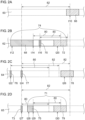
- Fig. 2 is a time chart showing steps in the first through third determination methods.
- Fig. 2A shows a step whereby a portion of band-shaped first video data 60 depicted in broken lines is saved according to the first determination method.
- the recording control unit 20 defines that the video data extending over a first save period 66 should be saved in response to the detection of a trigger event such as an accident at a point of time t10.
- the first determination method is executed on the condition that a marking event does not occur in a period of time going back at least a second standby period 82 from t10.
- the first determination method is executed on the condition that the trigger event is detected after an elapse of the standby periods for all previously detected marking events (i.e., the longest of the standby periods defined for the respective marking events).
- the recording control unit 20 defines that the video data for the first save period 66, i.e., the 15-second video data between t10-5 seconds and t10+10 seconds, should be saved.
- Fig. 2B shows a step whereby a portion of band-shaped second video data 62 depicted in broken lines is saved according to the second determination method.
- a first marking event 68 is an event of a type in which a predetermined period of time (e.g., 3 seconds) lasts for detection thereof or an event of a type detected continuously at an interval less than a predetermined period (e.g., 2 seconds).
- a period from a point of time preceding t12 by a short period of time to a point of time of t14 is regarded as a single event.
- the recording control unit 20 records t14, when the first marking event 68 ends, as the point of time of detection of the first marking event 68 in the recording medium 48.
- t12 when the first marking event is detected, may be recorded in the recording medium 48.
- the recording control unit 20 defines that video data should be saved in response to the detection of a trigger event such as an accident at t20, which is included in a period during which a first standby period 80 (e.g., 30 seconds) elapses since the point of time t14.
- the recording control unit 20 defines that data going back by a predetermined period of time (e.g., 1 second) from t12, when the first marking event 68 is detected, should be saved instead of only defining the 15-second video portion (illustrated as "virtual save period 72") between t20-5 seconds and t20+10 seconds should be saved.
- a second save period 74 between t12-1 second to t20+10 seconds should be saved in the form of one continuous item of video data.
- the second marking event 70 is, for example, an event such as manipulation of the direction indicator that is completed instantaneously, i.e., an event of a type for which detection thereof does not last for a predetermined period of time (e.g., 3 seconds) or longer.
- the recording control unit 20 records t16, when the second marking event 70 is detected, as the point of time of detection of the second marking event 70 in the recording medium 48.
- the recording control unit 20 defines the video portion for the second save period 74, including the video portion of the second marking event 70, in the form of one continuous item of video data.
- the recording control unit 20 would define that the video data going back 1 second from t16 should be saved, in response to the detection of a trigger event at t20 until the first standby period 80 elapses since t16. In this case, the recording control unit 20 defines that a period between t16-1 second and t20+10 seconds should be saved in the form of one continuous item of video data.
- Fig. 2C shows a step whereby a portion of band-shaped third video data 64 depicted in broken lines is saved according to the third determination method.
- the fourth marking event 77 is an event of a type for which detection thereof does not last for a predetermined period of time (e.g., 3 seconds) or longer.
- the recording control unit 20 records t24, when the fourth marking event 77 is detected, as the point of time of detection of the fourth marking event 77 in the recording medium 48.
- a trigger event such as an accident is not detected before the first standby period 80 elapses since the point of time t24 so that the second determination method is not executed.
- the third detection method is executed in response to the detection of a trigger event such as an accident at t26, which is included in a period in which the second standby period 82 elapses since the point of time t24.
- a trigger event such as an accident at t26
- the video data including t24 and the video data including t26 should be saved such that they are associated with each other.
- the video data for 2 seconds between t24-1 second and t24+1 second should be saved as video data for the fourth marking event 77, and it is defined that the video data for 15 seconds between t26-5 seconds and t26+10 seconds should be saved as video data for the third save period 78.
- Information that associates the video data with each other may be written in the video data or written in a management file separate from the video data.
- a third marking event 76 is detected at t22 that precedes t24, and the point of time of detection thereof is recorded in the recording medium 48.
- t26 is not included or a trigger event such as another accident is not detected in a period in which the second standby period 82 elapses since the point of time t22. Therefore, the third marking event 76 is not associated with the trigger event at t26, and it is not defined that the video data for the third marking event 76 should be saved.
- FIG. 2D shows a step whereby a portion of band-shaped fourth video data 65 depicted in broken lines is saved according to a combination of the second and third determination methods.
- a sixth marking event 75 is, like the first marking event 68 of (b), is an event of a type in which detection thereof lasts for a predetermined period of time or longer or an event of a type detected continuously at an interval less than a predetermined period. A period from a point of time slightly preceding t28 to t29 is regarded as a single event.
- the recording control unit 20 records t29, when the sixth marking event 75 ends, as the point of time of detection of the sixth marking event 75 in the recording medium 48.
- the recording control unit 20 defines that video data should be saved in response to the detection of a trigger event such as an accident at t30, which is included in a period during which the first standby period 80 (e.g., 30 seconds) elapses since the point of time t29.
- the recording control unit 20 defines that the data going back by a predetermined period of time (e.g., 1 second) from t28, when the sixth marking event 75 is detected, should be saved instead of defining that only the 15-second (illustrated as "virtual save period 79") video portion between t30-5 seconds and t30+10 seconds should be saved.
- a trigger event such as an accident at t30
- the recording control unit 20 defines that the data going back by a predetermined period of time (e.g., 1 second) from t28, when the sixth marking event 75 is detected, should be saved instead of defining that only the 15-second (illustrated as "virtual save period 79") video portion between t30-5 seconds and t
- a fifth marking event 73 is also detected before the sixth marking event 75.
- the recording control unit 20 records t27, when the fifth marking event 73 is detected, as the point of time of detection of the fifth marking event 73 in the recording medium 48.
- a trigger event is not detected until the first standby period 80 elapses since t27, but a trigger event is detected at t30 during the second standby period 82, in response to which the third detection method is executed.
- the sixth marking event 75 is detected (t28) during the first standby period 80 since t27, which is the point of time of detection of the fifth marking event 73.
- a trigger event is detected during the first standby period 80 from the point of time of detection (t28 or t29).
- the specification may require that, when a trigger event is detected after a succession of marking events during the first standby period defined for the respective marking events, one continuous item of video data going back to the first marking event in succession be saved. In other words, when marking events occur in succession without an interval equal to or longer than the standby period, continuous video data for a long period of time going back to the first marking event may be saved.
- the specification may require that a standby time is defined for the trigger event as well.
- a standby period may be defined for a particular trigger event of a plurality of types of trigger events. Individual standby periods may be defined for respective trigger events.
- one item of continuous video data including the plurality of trigger events should be saved.
- a video of a long period of time for a succession of trigger events is saved. For example, a video can be saved over a long period of time when the user is afflicted by aggressive driving for a distance as long as several km or for a long period of time.
- the first standby period 80 lasts 30 seconds and the second standby period 82 last 60 seconds commonly for the marking events, in order to facilitate the comparison between (a)-(c).
- the first standby period 80 is defined to have an individual duration for each marking event
- the second standby period 82 is also defined to have an individual duration for each marking event.
- an optimum duration is defined for the first standby period 80 to suit the situation of the memory card.
- the first standby period 80 may be a fixed period of time shorter than the second standby period 82, or the second standby period 82 may be a variable period of time.
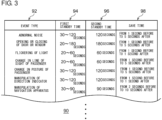
- Fig. 3 shows a table showing an exemplary correspondence between standby period and save time for each marking event.
- the recording control unit 20 refers to a marking event table 90 as illustrated and defines, for each marking event, the first standby period, the second standby period, and save time (duration), the save time being set when it is defined that the marking event should be saved.
- types of marking events such as "abnormal noise", “opening or closing of door or window”, “flickering of light”, “change in line of sight of passenger”, “change in posture of passenger”, “manipulation of direction indicator", and "manipulation of navigation apparatus".
- the first standby period, the second standby period, and the save time are defined for each marking event in the fields for the first standby period 94, the second standby period 96, and the save time 98.
- the first standby period is defined to have a lower limit of 30 seconds and an upper limit of 120 seconds, and the second standby period is defined to be 120 seconds.
- the first standby period is defined to be 20-180 seconds, and the second standby period is defined to be 180 seconds.
- the first standby period is defined to be 20-60 seconds
- the second standby period is defined to be 60 seconds.
- the first standby period is defined to be 20-60 seconds
- the second standby period is defined to be 60 seconds.
- the first standby period is defined to be 30-120 seconds, and the second standby period is defined to be 120 seconds.
- the first standby period is defined to be 30-120 seconds, and the second standby period is defined to be 120 seconds.
- the first standby period is defined to be 30-90 seconds
- the second standby period is defined to be 90 seconds.
- a variable value of the first standby period for which the lower limit and the upper limit are defined, is illustrated by way of example, and the upper limit having a value equal to the second standby period is illustrated by way of example.
- the lower limit may be 0 second, and the upper limit may be shorter than the second standby period.
- the first standby period may have a fixed value.
- the second standby period may have a variable value defined in accordance with the situation of the available capacity of the memory card. A period of time longer than the second standby period is not defined as the first standby period even if the second standby period is defined to be variable.
- Fig. 4 is a flowchart showing a step of saving a video according to the invention.
- the recording control unit 20 records a point of time of detection thereof in the recording medium 48 (S32).
- N in S30 When a new marking event is not detected (N in S30), and when a new trigger event is not detected, either (N in S34), control returns to the start of the flow, and the point of time of detection of a marking event is recorded every time it is detected (Y in S30, S32).
- the video data for a period before or after the marking event and the video data of S38 are associated with each other and saved (S40).
- the combination of S38 and S40 is a combination of the second and third determination methods shown in Fig. 2D .
- S40 is skipped. This represents the second determination method.
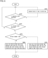
- This embodiment differs from the invention, in which two standby periods including the first standby period and the second standby period are defined for each marking event, in that one standby period is defined for each marking event.
- two standby periods including the first standby period and the second standby period are defined for each marking event, in that one standby period is defined for each marking event.
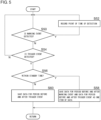
- Fig. 5 is a flowchart showing a step of saving a video according to embodiment 2.
- the recording control unit 20 records a point of time of detection thereof in the recording medium 48 (S52).
- N in S50 When a new marking event is not detected (N in S50), and when a new trigger event is not detected, either (N in S54), control returns to the start of the flow, and the point of time of detection of a marking event is recorded every time it is detected (Y in S50, S52).
- This embodiment is similar to embodiment 2 in that one standby period is defined for each marking event but differs from embodiment 2 in terms of the determination method executed when a trigger event is detected after an elapse of the standby period.
- This embodiment also differs from invention in which two standby periods including the first standby period and the second standby period are defined for each marking event.
- two standby periods including the first standby period and the second standby period are defined for each marking event.
- Fig. 6 is a flowchart showing a step of saving a video according to embodiment 3.
- the recording control unit 20 records a point of time of detection thereof in the recording medium 48 (S72).
- N in S70 When a new marking event is not detected (N in S70), and when a new trigger event is not detected, either (N in S74), control returns to the start of the flow, and the point of time of detection of a marking event is recorded every time it is detected (Y in S70, S72).
- the period of time tracked back to find a point of start of video data that should be saved can be extended in accordance with the actual duration of the period of time from the marking event to the trigger event so as to avoid saving video for a long period of time purposelessly.
- the standby period can be set to the most appropriate time to suit the overall capacity of the memory card or the situation of the available capacity so that depletion of the available capacity of the memory card is avoided.
- it can be defined that the video of an event that may have certain relevance to an accident or a trouble should be saved when a trigger event occurs after an elapse of a period of time longer than the first standby period since the detection of the marking event.
Landscapes
- Engineering & Computer Science (AREA)
- Multimedia (AREA)
- Signal Processing (AREA)
- Physics & Mathematics (AREA)
- General Physics & Mathematics (AREA)
- Theoretical Computer Science (AREA)
- Chemical & Material Sciences (AREA)
- Analytical Chemistry (AREA)
- Traffic Control Systems (AREA)
- Closed-Circuit Television Systems (AREA)
- Time Recorders, Dirve Recorders, Access Control (AREA)
- Television Signal Processing For Recording (AREA)
Claims (4)
- Appareil de commande d'enregistrement (10) comprenant :une unité d'acquisition vidéo (12) configurée pour acquérir des données vidéo capturant une scène autour d'un véhicule ;une unité de commande d'enregistrement (20) configurée pour enregistrer les données vidéo dans une zone prédéterminée et définir qu'au moins une partie des données vidéo doit être sauvegardée ; etune unité de détection d'événement (18) configurée pour détecter l'occurrence d'événements prédéfinis, dans lequell'unité de détection d'événement (18) est configurée pour détecter un événement de déclenchement, qui est un événement de déclenchement de sauvegarde qui déclenche la sauvegarde des données vidéo, ou un événement de marquage, qui est un événement ne déclenchant pas la sauvegarde, qui est différent de l'événement de déclenchement et pour lequel il est défini qu'un moment de détection de celui-ci doit être enregistré,l'unité de commande d'enregistrement (20) est en outre configurée pourenregistrer, lorsque l'unité de détection d'événement (18) détecte l'événement de marquage, le moment de détection de l'événement de marquage, etdéfinir, lorsque l'unité de détection d'événement (18) détecte l'événement de déclenchement dans une première période d'attente définie en association avec l'événement de marquage après la détection de l'événement de marquage, que des données vidéo continues pendant une période de temps incluant à la fois le moment de détection de l'événement de marquage et le moment de détection de l'événement de déclenchement doivent être sauvegardées comme étant invalides d'écrasement,définir, lorsque l'unité de détection d'événement (18) détecte l'événement de déclenchement en dehors de la première période d'attente mais dans une seconde période d'attente, définie en association avec l'événement de marquage et plus longue que la première période d'attente, après la détection de l'événement de marquage, que des données vidéo incluant une vidéo au moment de détection de l'événement de marquage et des données vidéo incluant une vidéo au moment de détection de l'événement de déclenchement doivent être associées les unes aux autres et sauvegardées séparément,l'unité de détection d'événement (18) est configurée pour détecter l'occurrence d'une pluralité de types d'événements en tant qu'événements de marquage, etdes périodes d'attente individuelles sont définies pour des types respectifs d'événements de marquage.
- Appareil de commande d'enregistrement (10) selon la revendication 1, dans lequel l'unité de commande d'enregistrement (20) est en outre configurée pour :
définir, lorsque l'événement de déclenchement est détecté après une succession d'événements de marquage pendant la première période d'attente définie pour les événements de marquage respectifs, qu'un élément continu de données vidéo revenant au premier événement de marquage en succession doit être sauvegardé. - Procédé de commande d'enregistrement comprenant :acquérir des données vidéo capturant une scène autour d'un véhicule ;enregistrer les données vidéo dans une zone prédéterminée ;lorsque l'occurrence d'un événement de déclenchement prédéfini pour déclencher la sauvegarde des données vidéo est détectée, définir que des données vidéo incluant un moment de détection de l'événement de déclenchement doivent être sauvegardées ; etdéfinir, lorsque l'occurrence d'un événement de marquage, qui est différent de l'événement de déclenchement et pour lequel il est défini qu'un moment de détection de celui-ci doit être enregistré, a été détectée avant l'événement de déclenchement et lorsque l'événement de déclenchement est détecté dans une première période d'attente définie en association avec l'événement de marquage après la détection de l'événement de marquage, que des données vidéo continues pendant une période incluant le moment de détection de l'événement de marquage et le moment de détection de l'événement de déclenchement doivent être sauvegardées comme étant invalides d'écrasement,définir, lorsque l'événement de déclenchement est détecté en dehors de la première période d'attente mais dans une seconde période d'attente qui est plus longue que la première période d'attente définie en association avec l'événement de marquage après la détection de l'événement de marquage, que des données vidéo incluant une vidéo au moment de détection de l'événement de marquage et des données vidéo incluant une vidéo au moment de détection de l'événement de déclenchement doivent être associées les unes aux autres et sauvegardées séparément, dans lequell'événement de marquage a une pluralité de types d'événements, et des périodes d'attente individuelles sont définies pour des types respectifs d'événements de marquage.
- Ordinateur de commande d'enregistrement comprenant des instructions pour amener l'appareil de commande d'enregistrement selon la revendication 1 à exécuter les étapes du procédé de commande d'enregistrement selon la revendication 3.
Applications Claiming Priority (2)
| Application Number | Priority Date | Filing Date | Title |
|---|---|---|---|
| JP2019175085A JP7327042B2 (ja) | 2019-09-26 | 2019-09-26 | 記録制御装置、記録制御方法、および記録制御プログラム |
| PCT/JP2020/033575 WO2021059924A1 (fr) | 2019-09-26 | 2020-09-04 | Dispositif de commande d'enregistrement, procédé de commande d'enregistrement et programme de commande d'enregistrement |
Publications (3)
| Publication Number | Publication Date |
|---|---|
| EP4036873A1 EP4036873A1 (fr) | 2022-08-03 |
| EP4036873A4 EP4036873A4 (fr) | 2022-11-16 |
| EP4036873B1 true EP4036873B1 (fr) | 2024-11-27 |
Family
ID=75158261
Family Applications (1)
| Application Number | Title | Priority Date | Filing Date |
|---|---|---|---|
| EP20870198.7A Active EP4036873B1 (fr) | 2019-09-26 | 2020-09-04 | Dispositif de commande d'enregistrement, procédé de commande d'enregistrement et programme de commande d'enregistrement |
Country Status (5)
| Country | Link |
|---|---|
| US (1) | US11895432B2 (fr) |
| EP (1) | EP4036873B1 (fr) |
| JP (1) | JP7327042B2 (fr) |
| CN (1) | CN114402371B (fr) |
| WO (1) | WO2021059924A1 (fr) |
Families Citing this family (11)
| Publication number | Priority date | Publication date | Assignee | Title |
|---|---|---|---|---|
| JP6828772B2 (ja) * | 2019-06-27 | 2021-02-10 | 株式会社Jvcケンウッド | 記録制御装置、記録装置、記録制御方法、及び記録制御プログラム |
| DE112020005125T5 (de) * | 2019-11-22 | 2022-07-21 | Hyundai Motor Company | System zum aufzeichnen von ereignisdaten eines autonomen fahrzeugs |
| CN114788255B (zh) * | 2020-01-31 | 2024-05-10 | Jvc建伍株式会社 | 记录控制装置、记录控制方法和存储介质 |
| GB202112053D0 (en) * | 2021-08-23 | 2021-10-06 | Safehinge Ltd | Methods and systems for monitoring mental health environment |
| WO2023074162A1 (fr) | 2021-10-29 | 2023-05-04 | 株式会社Jvcケンウッド | Dispositif de commande d'enregistrement et procédé de commande d'enregistrement de véhicule |
| JP2023151512A (ja) * | 2022-03-31 | 2023-10-16 | 株式会社ユピテル | システムおよびプログラム等 |
| CN115063904A (zh) * | 2022-05-18 | 2022-09-16 | 合众新能源汽车有限公司 | 一种车机端事件相关行车记录方法及系统 |
| FR3140826A1 (fr) * | 2022-10-16 | 2024-04-19 | Anthony SIRE | Dispositif de caméra embarquée pour véhicule |
| JP7828875B2 (ja) * | 2022-11-14 | 2026-03-12 | Astemo株式会社 | 車両データ収集装置及び車両データ収集システム |
| JP7588357B2 (ja) * | 2023-01-30 | 2024-11-22 | パナソニックIpマネジメント株式会社 | 映像管理装置、映像管理方法、及び、映像管理プログラム |
| WO2025115217A1 (fr) | 2023-12-01 | 2025-06-05 | Astemo株式会社 | Dispositif de collecte vidéo et système de collecte vidéo |
Family Cites Families (12)
| Publication number | Priority date | Publication date | Assignee | Title |
|---|---|---|---|---|
| JP5344339B2 (ja) * | 2008-09-29 | 2013-11-20 | 国立大学法人東京農工大学 | ドライブレコーダ |
| JP5618627B2 (ja) * | 2010-05-27 | 2014-11-05 | 矢崎エナジーシステム株式会社 | 車両用ドライブレコーダおよび記録情報管理方法 |
| JP5650444B2 (ja) * | 2010-06-18 | 2015-01-07 | 矢崎エナジーシステム株式会社 | 車両用ドライブレコーダおよび記録情報管理方法 |
| JP5896263B2 (ja) * | 2011-01-31 | 2016-03-30 | 矢崎エナジーシステム株式会社 | 画像記録制御方法および車載画像記録装置 |
| JP2018032885A (ja) * | 2014-05-15 | 2018-03-01 | パナソニック インテレクチュアル プロパティ コーポレーション オブ アメリカPanasonic Intellectual Property Corporation of America | 情報処理プログラム、受信プログラムおよび情報処理装置 |
| EP3073449A1 (fr) * | 2015-03-23 | 2016-09-28 | Continental Automotive GmbH | Appareil et procédé d'enregistrement de données associées à un véhicule |
| KR20160146343A (ko) * | 2015-06-12 | 2016-12-21 | 엘지전자 주식회사 | 위치 정보를 기반으로 하는 블랙박스 영상 공유 방법 및 이를 이용한 단말기 |
| JP6432490B2 (ja) * | 2015-11-20 | 2018-12-05 | トヨタ自動車株式会社 | 車載制御装置、及び、車載記録システム |
| JP2017138694A (ja) * | 2016-02-02 | 2017-08-10 | ソニー株式会社 | 映像処理装置及び映像処理方法 |
| CN107102936B (zh) * | 2017-05-27 | 2021-06-15 | 腾讯科技(深圳)有限公司 | 一种流畅度的评估方法和移动终端以及存储介质 |
| JP6866982B2 (ja) * | 2017-08-24 | 2021-04-28 | 株式会社デンソーテン | 車両データ記録装置及び車両データ記録システム |
| JP6593431B2 (ja) * | 2017-12-27 | 2019-10-23 | 株式会社Jvcケンウッド | 記録制御装置、記録装置、記録制御方法及び記録制御プログラム |
-
2019
- 2019-09-26 JP JP2019175085A patent/JP7327042B2/ja active Active
-
2020
- 2020-09-04 EP EP20870198.7A patent/EP4036873B1/fr active Active
- 2020-09-04 WO PCT/JP2020/033575 patent/WO2021059924A1/fr not_active Ceased
- 2020-09-04 CN CN202080064388.5A patent/CN114402371B/zh active Active
-
2022
- 2022-03-18 US US17/698,328 patent/US11895432B2/en active Active
Also Published As
| Publication number | Publication date |
|---|---|
| JP2021051628A (ja) | 2021-04-01 |
| EP4036873A1 (fr) | 2022-08-03 |
| US20220217298A1 (en) | 2022-07-07 |
| JP7327042B2 (ja) | 2023-08-16 |
| CN114402371A (zh) | 2022-04-26 |
| CN114402371B (zh) | 2023-12-05 |
| EP4036873A4 (fr) | 2022-11-16 |
| US11895432B2 (en) | 2024-02-06 |
| WO2021059924A1 (fr) | 2021-04-01 |
Similar Documents
| Publication | Publication Date | Title |
|---|---|---|
| EP4036873B1 (fr) | Dispositif de commande d'enregistrement, procédé de commande d'enregistrement et programme de commande d'enregistrement | |
| EP3509038B1 (fr) | Enregistreur de conduite | |
| JP6817531B2 (ja) | 運転状況記録装置 | |
| US11265508B2 (en) | Recording control device, recording control system, recording control method, and recording control program | |
| JP7247790B2 (ja) | 走行環境監視装置、走行環境監視システム、及び走行環境監視プログラム | |
| US10964348B2 (en) | Recording control apparatus, recording apparatus, recording control method, and recording control program | |
| WO2018207405A1 (fr) | Dispositif de commande d'enregistrement, dispositif d'enregistrement, procédé de commande d'enregistrement et programme de commande d'enregistrement | |
| CN108399777A (zh) | 一种辅助驾驶方法、装置及电子设备 | |
| JP6345572B2 (ja) | 走行映像記録システムおよびこれに用いるドライブレコーダ、並びに記録走行映像のアップロード方法 | |
| EP3614358A1 (fr) | Dispositif de commande d'enregistrement, appareil d'enregistrement, appareil de navigation, procédé d'enregistrement et programme | |
| US11750771B2 (en) | Recording control apparatus, recording control method, and recording control program | |
| US11539913B2 (en) | Recording control device, recording control system, recording control method, and computer program | |
| EP3511911B1 (fr) | Système de sortie vidéo | |
| JP6367531B2 (ja) | 車載器 | |
| JP6244129B2 (ja) | 車載器 | |
| KR101438563B1 (ko) | 차량용 블랙박스의 연속 영상촬영 장치 | |
| JP2019008588A (ja) | 記録制御装置、記録装置、記録制御方法及び記録制御プログラム | |
| JP2021150901A (ja) | 運転情報記録装置、運転情報再生システム、及び運転情報記録方法 | |
| JP7447455B2 (ja) | 車両用記録制御装置および車両用記録制御方法 | |
| JP2022136534A (ja) | 画像記録装置 | |
| KR20080091587A (ko) | 차량용 복합 장치 및 이의 제어 방법 | |
| JP7310962B2 (ja) | ドライブレコーダ | |
| JP2021040302A (ja) | 記録制御装置、記録制御方法、およびプログラム | |
| JP2021051602A (ja) | 車両用記録制御装置、車両用記録装置、車両用記録制御方法およびプログラム | |
| JP2021051558A (ja) | 記録制御装置、記録制御方法、およびプログラム |
Legal Events
| Date | Code | Title | Description |
|---|---|---|---|
| STAA | Information on the status of an ep patent application or granted ep patent |
Free format text: STATUS: THE INTERNATIONAL PUBLICATION HAS BEEN MADE |
|
| PUAI | Public reference made under article 153(3) epc to a published international application that has entered the european phase |
Free format text: ORIGINAL CODE: 0009012 |
|
| STAA | Information on the status of an ep patent application or granted ep patent |
Free format text: STATUS: REQUEST FOR EXAMINATION WAS MADE |
|
| 17P | Request for examination filed |
Effective date: 20220318 |
|
| AK | Designated contracting states |
Kind code of ref document: A1 Designated state(s): AL AT BE BG CH CY CZ DE DK EE ES FI FR GB GR HR HU IE IS IT LI LT LU LV MC MK MT NL NO PL PT RO RS SE SI SK SM TR |
|
| A4 | Supplementary search report drawn up and despatched |
Effective date: 20221018 |
|
| RIC1 | Information provided on ipc code assigned before grant |
Ipc: H04N 7/18 20060101ALI20221012BHEP Ipc: H04N 5/92 20060101ALI20221012BHEP Ipc: H04N 5/77 20060101ALI20221012BHEP Ipc: G07C 5/00 20060101AFI20221012BHEP |
|
| DAV | Request for validation of the european patent (deleted) | ||
| DAX | Request for extension of the european patent (deleted) | ||
| STAA | Information on the status of an ep patent application or granted ep patent |
Free format text: STATUS: EXAMINATION IS IN PROGRESS |
|
| 17Q | First examination report despatched |
Effective date: 20230719 |
|
| GRAP | Despatch of communication of intention to grant a patent |
Free format text: ORIGINAL CODE: EPIDOSNIGR1 |
|
| STAA | Information on the status of an ep patent application or granted ep patent |
Free format text: STATUS: GRANT OF PATENT IS INTENDED |
|
| INTG | Intention to grant announced |
Effective date: 20240704 |
|
| GRAS | Grant fee paid |
Free format text: ORIGINAL CODE: EPIDOSNIGR3 |
|
| GRAA | (expected) grant |
Free format text: ORIGINAL CODE: 0009210 |
|
| STAA | Information on the status of an ep patent application or granted ep patent |
Free format text: STATUS: THE PATENT HAS BEEN GRANTED |
|
| AK | Designated contracting states |
Kind code of ref document: B1 Designated state(s): AL AT BE BG CH CY CZ DE DK EE ES FI FR GB GR HR HU IE IS IT LI LT LU LV MC MK MT NL NO PL PT RO RS SE SI SK SM TR |
|
| REG | Reference to a national code |
Ref country code: GB Ref legal event code: FG4D |
|
| REG | Reference to a national code |
Ref country code: CH Ref legal event code: EP |
|
| REG | Reference to a national code |
Ref country code: DE Ref legal event code: R096 Ref document number: 602020042253 Country of ref document: DE |
|
| REG | Reference to a national code |
Ref country code: IE Ref legal event code: FG4D |
|
| REG | Reference to a national code |
Ref country code: LT Ref legal event code: MG9D |
|
| REG | Reference to a national code |
Ref country code: NL Ref legal event code: MP Effective date: 20241127 |
|
| PG25 | Lapsed in a contracting state [announced via postgrant information from national office to epo] |
Ref country code: PT Free format text: LAPSE BECAUSE OF FAILURE TO SUBMIT A TRANSLATION OF THE DESCRIPTION OR TO PAY THE FEE WITHIN THE PRESCRIBED TIME-LIMIT Effective date: 20250327 Ref country code: IS Free format text: LAPSE BECAUSE OF FAILURE TO SUBMIT A TRANSLATION OF THE DESCRIPTION OR TO PAY THE FEE WITHIN THE PRESCRIBED TIME-LIMIT Effective date: 20250327 Ref country code: HR Free format text: LAPSE BECAUSE OF FAILURE TO SUBMIT A TRANSLATION OF THE DESCRIPTION OR TO PAY THE FEE WITHIN THE PRESCRIBED TIME-LIMIT Effective date: 20241127 |
|
| PG25 | Lapsed in a contracting state [announced via postgrant information from national office to epo] |
Ref country code: FI Free format text: LAPSE BECAUSE OF FAILURE TO SUBMIT A TRANSLATION OF THE DESCRIPTION OR TO PAY THE FEE WITHIN THE PRESCRIBED TIME-LIMIT Effective date: 20241127 Ref country code: NL Free format text: LAPSE BECAUSE OF FAILURE TO SUBMIT A TRANSLATION OF THE DESCRIPTION OR TO PAY THE FEE WITHIN THE PRESCRIBED TIME-LIMIT Effective date: 20241127 |
|
| REG | Reference to a national code |
Ref country code: AT Ref legal event code: MK05 Ref document number: 1746479 Country of ref document: AT Kind code of ref document: T Effective date: 20241127 |
|
| PG25 | Lapsed in a contracting state [announced via postgrant information from national office to epo] |
Ref country code: BG Free format text: LAPSE BECAUSE OF FAILURE TO SUBMIT A TRANSLATION OF THE DESCRIPTION OR TO PAY THE FEE WITHIN THE PRESCRIBED TIME-LIMIT Effective date: 20241127 |
|
| PG25 | Lapsed in a contracting state [announced via postgrant information from national office to epo] |
Ref country code: ES Free format text: LAPSE BECAUSE OF FAILURE TO SUBMIT A TRANSLATION OF THE DESCRIPTION OR TO PAY THE FEE WITHIN THE PRESCRIBED TIME-LIMIT Effective date: 20241127 |
|
| PG25 | Lapsed in a contracting state [announced via postgrant information from national office to epo] |
Ref country code: NO Free format text: LAPSE BECAUSE OF FAILURE TO SUBMIT A TRANSLATION OF THE DESCRIPTION OR TO PAY THE FEE WITHIN THE PRESCRIBED TIME-LIMIT Effective date: 20250227 |
|
| PG25 | Lapsed in a contracting state [announced via postgrant information from national office to epo] |
Ref country code: LV Free format text: LAPSE BECAUSE OF FAILURE TO SUBMIT A TRANSLATION OF THE DESCRIPTION OR TO PAY THE FEE WITHIN THE PRESCRIBED TIME-LIMIT Effective date: 20241127 Ref country code: GR Free format text: LAPSE BECAUSE OF FAILURE TO SUBMIT A TRANSLATION OF THE DESCRIPTION OR TO PAY THE FEE WITHIN THE PRESCRIBED TIME-LIMIT Effective date: 20250228 Ref country code: AT Free format text: LAPSE BECAUSE OF FAILURE TO SUBMIT A TRANSLATION OF THE DESCRIPTION OR TO PAY THE FEE WITHIN THE PRESCRIBED TIME-LIMIT Effective date: 20241127 |
|
| PG25 | Lapsed in a contracting state [announced via postgrant information from national office to epo] |
Ref country code: PL Free format text: LAPSE BECAUSE OF FAILURE TO SUBMIT A TRANSLATION OF THE DESCRIPTION OR TO PAY THE FEE WITHIN THE PRESCRIBED TIME-LIMIT Effective date: 20241127 |
|
| PG25 | Lapsed in a contracting state [announced via postgrant information from national office to epo] |
Ref country code: RS Free format text: LAPSE BECAUSE OF FAILURE TO SUBMIT A TRANSLATION OF THE DESCRIPTION OR TO PAY THE FEE WITHIN THE PRESCRIBED TIME-LIMIT Effective date: 20250227 |
|
| PG25 | Lapsed in a contracting state [announced via postgrant information from national office to epo] |
Ref country code: SM Free format text: LAPSE BECAUSE OF FAILURE TO SUBMIT A TRANSLATION OF THE DESCRIPTION OR TO PAY THE FEE WITHIN THE PRESCRIBED TIME-LIMIT Effective date: 20241127 |
|
| PG25 | Lapsed in a contracting state [announced via postgrant information from national office to epo] |
Ref country code: DK Free format text: LAPSE BECAUSE OF FAILURE TO SUBMIT A TRANSLATION OF THE DESCRIPTION OR TO PAY THE FEE WITHIN THE PRESCRIBED TIME-LIMIT Effective date: 20241127 |
|
| PG25 | Lapsed in a contracting state [announced via postgrant information from national office to epo] |
Ref country code: EE Free format text: LAPSE BECAUSE OF FAILURE TO SUBMIT A TRANSLATION OF THE DESCRIPTION OR TO PAY THE FEE WITHIN THE PRESCRIBED TIME-LIMIT Effective date: 20241127 |
|
| PG25 | Lapsed in a contracting state [announced via postgrant information from national office to epo] |
Ref country code: RO Free format text: LAPSE BECAUSE OF FAILURE TO SUBMIT A TRANSLATION OF THE DESCRIPTION OR TO PAY THE FEE WITHIN THE PRESCRIBED TIME-LIMIT Effective date: 20241127 |
|
| PG25 | Lapsed in a contracting state [announced via postgrant information from national office to epo] |
Ref country code: SK Free format text: LAPSE BECAUSE OF FAILURE TO SUBMIT A TRANSLATION OF THE DESCRIPTION OR TO PAY THE FEE WITHIN THE PRESCRIBED TIME-LIMIT Effective date: 20241127 |
|
| PG25 | Lapsed in a contracting state [announced via postgrant information from national office to epo] |
Ref country code: CZ Free format text: LAPSE BECAUSE OF FAILURE TO SUBMIT A TRANSLATION OF THE DESCRIPTION OR TO PAY THE FEE WITHIN THE PRESCRIBED TIME-LIMIT Effective date: 20241127 |
|
| PG25 | Lapsed in a contracting state [announced via postgrant information from national office to epo] |
Ref country code: IT Free format text: LAPSE BECAUSE OF FAILURE TO SUBMIT A TRANSLATION OF THE DESCRIPTION OR TO PAY THE FEE WITHIN THE PRESCRIBED TIME-LIMIT Effective date: 20241127 |
|
| REG | Reference to a national code |
Ref country code: DE Ref legal event code: R097 Ref document number: 602020042253 Country of ref document: DE |
|
| PG25 | Lapsed in a contracting state [announced via postgrant information from national office to epo] |
Ref country code: SE Free format text: LAPSE BECAUSE OF FAILURE TO SUBMIT A TRANSLATION OF THE DESCRIPTION OR TO PAY THE FEE WITHIN THE PRESCRIBED TIME-LIMIT Effective date: 20241127 |
|
| PLBE | No opposition filed within time limit |
Free format text: ORIGINAL CODE: 0009261 |
|
| STAA | Information on the status of an ep patent application or granted ep patent |
Free format text: STATUS: NO OPPOSITION FILED WITHIN TIME LIMIT |
|
| PGFP | Annual fee paid to national office [announced via postgrant information from national office to epo] |
Ref country code: DE Payment date: 20250730 Year of fee payment: 6 |
|
| 26N | No opposition filed |
Effective date: 20250828 |