EP4037085A1 - Batteriepack, das eine struktur mit erhöhter beweglichkeit und einfachem zusammensetzen und eine struktur mit verbesserter sicherheit aufweist, sowie ess damit - Google Patents
Batteriepack, das eine struktur mit erhöhter beweglichkeit und einfachem zusammensetzen und eine struktur mit verbesserter sicherheit aufweist, sowie ess damit Download PDFInfo
- Publication number
- EP4037085A1 EP4037085A1 EP21772158.8A EP21772158A EP4037085A1 EP 4037085 A1 EP4037085 A1 EP 4037085A1 EP 21772158 A EP21772158 A EP 21772158A EP 4037085 A1 EP4037085 A1 EP 4037085A1
- Authority
- EP
- European Patent Office
- Prior art keywords
- cover
- battery pack
- battery
- bms
- pack according
- Prior art date
- Legal status (The legal status is an assumption and is not a legal conclusion. Google has not performed a legal analysis and makes no representation as to the accuracy of the status listed.)
- Pending
Links
Images






Classifications
-
- H—ELECTRICITY
- H01—ELECTRIC ELEMENTS
- H01M—PROCESSES OR MEANS, e.g. BATTERIES, FOR THE DIRECT CONVERSION OF CHEMICAL ENERGY INTO ELECTRICAL ENERGY
- H01M10/00—Secondary cells; Manufacture thereof
- H01M10/42—Methods or arrangements for servicing or maintenance of secondary cells or secondary half-cells
- H01M10/425—Structural combination with electronic components, e.g. electronic circuits integrated to the outside of the casing
-
- H—ELECTRICITY
- H01—ELECTRIC ELEMENTS
- H01M—PROCESSES OR MEANS, e.g. BATTERIES, FOR THE DIRECT CONVERSION OF CHEMICAL ENERGY INTO ELECTRICAL ENERGY
- H01M50/00—Constructional details or processes of manufacture of the non-active parts of electrochemical cells other than fuel cells, e.g. hybrid cells
- H01M50/30—Arrangements for facilitating escape of gases
- H01M50/35—Gas exhaust passages comprising elongated, tortuous or labyrinth-shaped exhaust passages
-
- H—ELECTRICITY
- H01—ELECTRIC ELEMENTS
- H01M—PROCESSES OR MEANS, e.g. BATTERIES, FOR THE DIRECT CONVERSION OF CHEMICAL ENERGY INTO ELECTRICAL ENERGY
- H01M10/00—Secondary cells; Manufacture thereof
- H01M10/42—Methods or arrangements for servicing or maintenance of secondary cells or secondary half-cells
-
- H—ELECTRICITY
- H01—ELECTRIC ELEMENTS
- H01M—PROCESSES OR MEANS, e.g. BATTERIES, FOR THE DIRECT CONVERSION OF CHEMICAL ENERGY INTO ELECTRICAL ENERGY
- H01M50/00—Constructional details or processes of manufacture of the non-active parts of electrochemical cells other than fuel cells, e.g. hybrid cells
- H01M50/20—Mountings; Secondary casings or frames; Racks, modules or packs; Suspension devices; Shock absorbers; Transport or carrying devices; Holders
-
- H—ELECTRICITY
- H01—ELECTRIC ELEMENTS
- H01M—PROCESSES OR MEANS, e.g. BATTERIES, FOR THE DIRECT CONVERSION OF CHEMICAL ENERGY INTO ELECTRICAL ENERGY
- H01M50/00—Constructional details or processes of manufacture of the non-active parts of electrochemical cells other than fuel cells, e.g. hybrid cells
- H01M50/20—Mountings; Secondary casings or frames; Racks, modules or packs; Suspension devices; Shock absorbers; Transport or carrying devices; Holders
- H01M50/204—Racks, modules or packs for multiple batteries or multiple cells
-
- H—ELECTRICITY
- H01—ELECTRIC ELEMENTS
- H01M—PROCESSES OR MEANS, e.g. BATTERIES, FOR THE DIRECT CONVERSION OF CHEMICAL ENERGY INTO ELECTRICAL ENERGY
- H01M50/00—Constructional details or processes of manufacture of the non-active parts of electrochemical cells other than fuel cells, e.g. hybrid cells
- H01M50/20—Mountings; Secondary casings or frames; Racks, modules or packs; Suspension devices; Shock absorbers; Transport or carrying devices; Holders
- H01M50/204—Racks, modules or packs for multiple batteries or multiple cells
- H01M50/207—Racks, modules or packs for multiple batteries or multiple cells characterised by their shape
- H01M50/211—Racks, modules or packs for multiple batteries or multiple cells characterised by their shape adapted for pouch cells
-
- H—ELECTRICITY
- H01—ELECTRIC ELEMENTS
- H01M—PROCESSES OR MEANS, e.g. BATTERIES, FOR THE DIRECT CONVERSION OF CHEMICAL ENERGY INTO ELECTRICAL ENERGY
- H01M50/00—Constructional details or processes of manufacture of the non-active parts of electrochemical cells other than fuel cells, e.g. hybrid cells
- H01M50/20—Mountings; Secondary casings or frames; Racks, modules or packs; Suspension devices; Shock absorbers; Transport or carrying devices; Holders
- H01M50/271—Lids or covers for the racks or secondary casings
-
- H—ELECTRICITY
- H01—ELECTRIC ELEMENTS
- H01M—PROCESSES OR MEANS, e.g. BATTERIES, FOR THE DIRECT CONVERSION OF CHEMICAL ENERGY INTO ELECTRICAL ENERGY
- H01M50/00—Constructional details or processes of manufacture of the non-active parts of electrochemical cells other than fuel cells, e.g. hybrid cells
- H01M50/20—Mountings; Secondary casings or frames; Racks, modules or packs; Suspension devices; Shock absorbers; Transport or carrying devices; Holders
- H01M50/289—Mountings; Secondary casings or frames; Racks, modules or packs; Suspension devices; Shock absorbers; Transport or carrying devices; Holders characterised by spacing elements or positioning means within frames, racks or packs
- H01M50/291—Mountings; Secondary casings or frames; Racks, modules or packs; Suspension devices; Shock absorbers; Transport or carrying devices; Holders characterised by spacing elements or positioning means within frames, racks or packs characterised by their shape
-
- H—ELECTRICITY
- H01—ELECTRIC ELEMENTS
- H01M—PROCESSES OR MEANS, e.g. BATTERIES, FOR THE DIRECT CONVERSION OF CHEMICAL ENERGY INTO ELECTRICAL ENERGY
- H01M50/00—Constructional details or processes of manufacture of the non-active parts of electrochemical cells other than fuel cells, e.g. hybrid cells
- H01M50/30—Arrangements for facilitating escape of gases
-
- H—ELECTRICITY
- H01—ELECTRIC ELEMENTS
- H01M—PROCESSES OR MEANS, e.g. BATTERIES, FOR THE DIRECT CONVERSION OF CHEMICAL ENERGY INTO ELECTRICAL ENERGY
- H01M50/00—Constructional details or processes of manufacture of the non-active parts of electrochemical cells other than fuel cells, e.g. hybrid cells
- H01M50/30—Arrangements for facilitating escape of gases
- H01M50/35—Gas exhaust passages comprising elongated, tortuous or labyrinth-shaped exhaust passages
- H01M50/367—Internal gas exhaust passages forming part of the battery cover or case; Double cover vent systems
-
- H—ELECTRICITY
- H01—ELECTRIC ELEMENTS
- H01M—PROCESSES OR MEANS, e.g. BATTERIES, FOR THE DIRECT CONVERSION OF CHEMICAL ENERGY INTO ELECTRICAL ENERGY
- H01M50/00—Constructional details or processes of manufacture of the non-active parts of electrochemical cells other than fuel cells, e.g. hybrid cells
- H01M50/50—Current conducting connections for cells or batteries
- H01M50/572—Means for preventing undesired use or discharge
-
- H—ELECTRICITY
- H01—ELECTRIC ELEMENTS
- H01M—PROCESSES OR MEANS, e.g. BATTERIES, FOR THE DIRECT CONVERSION OF CHEMICAL ENERGY INTO ELECTRICAL ENERGY
- H01M50/00—Constructional details or processes of manufacture of the non-active parts of electrochemical cells other than fuel cells, e.g. hybrid cells
- H01M50/50—Current conducting connections for cells or batteries
- H01M50/572—Means for preventing undesired use or discharge
- H01M50/574—Devices or arrangements for the interruption of current
- H01M50/581—Devices or arrangements for the interruption of current in response to temperature
-
- H—ELECTRICITY
- H01—ELECTRIC ELEMENTS
- H01M—PROCESSES OR MEANS, e.g. BATTERIES, FOR THE DIRECT CONVERSION OF CHEMICAL ENERGY INTO ELECTRICAL ENERGY
- H01M50/00—Constructional details or processes of manufacture of the non-active parts of electrochemical cells other than fuel cells, e.g. hybrid cells
- H01M50/50—Current conducting connections for cells or batteries
- H01M50/572—Means for preventing undesired use or discharge
- H01M50/574—Devices or arrangements for the interruption of current
- H01M50/583—Devices or arrangements for the interruption of current in response to current, e.g. fuses
-
- H—ELECTRICITY
- H01—ELECTRIC ELEMENTS
- H01M—PROCESSES OR MEANS, e.g. BATTERIES, FOR THE DIRECT CONVERSION OF CHEMICAL ENERGY INTO ELECTRICAL ENERGY
- H01M10/00—Secondary cells; Manufacture thereof
- H01M10/42—Methods or arrangements for servicing or maintenance of secondary cells or secondary half-cells
- H01M10/425—Structural combination with electronic components, e.g. electronic circuits integrated to the outside of the casing
- H01M2010/4271—Battery management systems including electronic circuits, e.g. control of current or voltage to keep battery in healthy state, cell balancing
-
- H—ELECTRICITY
- H01—ELECTRIC ELEMENTS
- H01M—PROCESSES OR MEANS, e.g. BATTERIES, FOR THE DIRECT CONVERSION OF CHEMICAL ENERGY INTO ELECTRICAL ENERGY
- H01M2200/00—Safety devices for primary or secondary batteries
- H01M2200/10—Temperature sensitive devices
- H01M2200/103—Fuse
-
- H—ELECTRICITY
- H01—ELECTRIC ELEMENTS
- H01M—PROCESSES OR MEANS, e.g. BATTERIES, FOR THE DIRECT CONVERSION OF CHEMICAL ENERGY INTO ELECTRICAL ENERGY
- H01M2220/00—Batteries for particular applications
- H01M2220/10—Batteries in stationary systems, e.g. emergency power source in plant
-
- Y—GENERAL TAGGING OF NEW TECHNOLOGICAL DEVELOPMENTS; GENERAL TAGGING OF CROSS-SECTIONAL TECHNOLOGIES SPANNING OVER SEVERAL SECTIONS OF THE IPC; TECHNICAL SUBJECTS COVERED BY FORMER USPC CROSS-REFERENCE ART COLLECTIONS [XRACs] AND DIGESTS
- Y02—TECHNOLOGIES OR APPLICATIONS FOR MITIGATION OR ADAPTATION AGAINST CLIMATE CHANGE
- Y02E—REDUCTION OF GREENHOUSE GAS [GHG] EMISSIONS, RELATED TO ENERGY GENERATION, TRANSMISSION OR DISTRIBUTION
- Y02E60/00—Enabling technologies; Technologies with a potential or indirect contribution to GHG emissions mitigation
- Y02E60/10—Energy storage using batteries
Definitions
- the present disclosure relates to a battery pack having a structure with improved convenience for carrying and assembling and improved safety, and an ESS including the battery pack, and more particularly, to a battery pack having a structure for fastening a plurality of battery modules by using a module fastening plate and a BMS assembly and a structure for preventing a flame generated at a battery cell provided therein from being leaked out of the battery pack, and an ESS including the battery pack.
- a battery pack used as an energy storage system is a kind of energy storage system configured to remove the risk caused by external physical factors during use and to function properly in consideration of the installation environment and use conditions.
- the battery pack used as an energy storage system may have a form in which a plurality of battery modules and a BMS assembly electrically connected to the battery modules are coupled.
- a battery pack for home use is often necessary to move through narrow stairs and/or passages.
- the battery pack used as an energy storage system has a relatively large volume and a relatively heavy weight in many cases, so the battery pack should be made in consideration of the convenience for carrying and installation.
- the battery pack used as an energy storage system includes a plurality of battery cells to ensure sufficient capacity and output, the battery pack needs to be designed to secure user safety in case an abnormal situation occurs during use.
- the present disclosure is designed to solve the problems of the related art, and therefore the present disclosure is directed to providing a battery pack having a structure with improved convenience for carrying and installation and improved safety during use.
- a battery pack comprising: a pair of battery modules having a plurality of first partition walls formed to extend downward from a lower surface thereof; a supporting plate having a plurality of second partition walls formed to extend upward from an upper surface thereof and a gas discharge hole formed at a longitudinal center thereof, the supporting plate being coupled to a bottom of the pair of battery modules such that the plurality of first partition walls and the plurality of second partition walls are adjacent and overlap each other in one-to-one pairs; and a BMS assembly coupled to an upper portion of the pair of battery modules in a plug-in type.
- the plurality of first partition walls may be spaced apart from the supporting plate, and the plurality of second partition walls may be spaced apart from the battery module.
- the plurality of first partition walls may be spaced apart from the supporting plate, and at least a part of the plurality of second partition walls may have a partition wall hole formed in a region that is in contact with the lower surface of the battery module and faces the first partition wall.
- the battery module may include a cell stack having a plurality of battery cells; a module housing configured to accommodate the cell stack; a lower cover configured to cover a bottom opening of the module housing; and an upper cover assembly configured to cover a top opening of the module housing.
- a gas channel may be formed between the cell stack and the module housing.
- the lower cover may have lower cover holes formed at both longitudinal sides thereof to communicate with the gas channel, respectively.
- a mesh filter may be inserted into at least one of the gas discharge hole and the lower cover hole.
- the upper cover assembly may include an upper cover configured to cover the top opening of the module housing, the upper cover having a connector formed at one longitudinal side thereof and an upper cover groove formed at a center thereof to be concave downward; a fuse fixed in the upper cover groove and electrically connected to the battery cell; a fuse cover configured to cover the fuse inside the upper cover groove; and a cover plate configured to cover a top of the upper cover groove and coupled to the upper cover.
- the cover plate may have at least one pair of cover plate holes and be spaced apart from the fuse cover so that a first grip groove is formed between the cover plate and the fuse cover.
- the BMS assembly may include a BMS body coupled to the pair of battery modules; and a BMS cover coupled to an upper portion of the BMS body.
- the battery pack may have second grip grooves formed between one longitudinal side and the other longitudinal side of the BMS cover and the BMS body, respectively.
- the BMS body may include a guide protrusion formed at a lower surface thereof and inserted into the first grip groove through the cover plate to guide coupling between the BMS assembly and the battery module.
- the battery pack may further comprise a gasket interposed between the guide protrusion and an inner surface of the cover plate hole.
- the supporting plate may be fixed to the ground.
- an ESS comprising at least one battery pack according to an embodiment of the present disclosure.
- a battery pack having a structure with improved convenience for carrying and installation and improved safety during use.
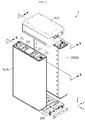
- FIGS. 1 and 2 a schematic structure of a battery pack 1 according to an embodiment of the present disclosure and a coupling relationship between respective components thereof will be described with reference to FIGS. 1 and 2 .
- the battery pack 1 includes a plurality of battery modules 100, a supporting plate 200, and a BMS assembly 300.
- the battery pack 1 may be, for example, an energy storage system (ESS) battery pack for energy storage.
- ESS energy storage system
- a bottom of the battery module 100 is inserted/fixed to the supporting plate 200, and the BMS assembly 300 is coupled to a top of the battery module 100.
- the supporting plate 200 may be fixed to the ground, thereby functioning as a bracket for fixing the plurality of battery modules 100.
- the ground means a floor surface of the place where the battery pack 1 is used for energy storage. That is, the ground may refer to a floor surface of a container or a floor surface of an indoor space of a building.
- the BMS assembly 300 includes at least one BMS (Battery Management System), and the BMS assembly 300 may be coupled to the top of the plurality of battery modules 100 in a plug-in type to mechanically fasten the plurality of battery modules 100 to each other and control charging and discharging for the plurality of battery modules 100.
- the BMS assembly 300 may enable electrical connection among the plurality of battery modules 100.
- the battery module 100 and the BMS assembly 300 may be coupled by combining a first connector C1 provided at an upper surface of the battery module 100 and a second connector C2 (see FIG. 7 ) provided at a lower surface of the BMS assembly 300.
- a plurality of first grip grooves G1 may be formed in the upper surface of the battery module 100
- a plurality of guide protrusions 311 provided in a shape and number corresponding to the plurality of first grip grooves G1 and inserted into the first grip grooves G1 may be formed at the lower surface of the BMS assembly 300 to guide the coupling between the battery module 100 and the BMS assembly 300.
- the battery module 100 includes a cell stack 110, a module housing 120, a lower cover 130, and an upper cover assembly 140.
- the cell stack 110 may include a plurality of battery cells electrically connected to each other, and may include additional components for mechanically coupling and/or electrically coupling the plurality of battery cells.
- a pouch-type battery cell may be applied as the battery cell used to configure the cell stack 110.
- the module housing 120 has an approximately rectangular parallelepiped shape with openings formed at the top and bottom thereof, respectively, and accommodates the cell stack 110 in the inner space thereof.
- the module housing 120 may have a form in which a front plate 121 and a rear plate 122 are combined.
- the structure of the module housing 120 is not limited thereto, and the module housing 120 may have an integrated structure, rather than a structure in which a plurality of pieces are combined, and alternatively, may have a form in which three or more pieces are combined.
- the lower cover 130 covers the bottom opening of the module housing 120 and supports the cell stack 110.
- the lower cover 130 has a special structure to induce gas to be discharged downward when internal gas and flame are generated due to abnormality of the battery pack 1 and also to minimize the external emission of the flame. This structure will be described later in detail with reference to FIGS. 10 and 11 , along with the specific structure of the supporting plate 200.
- the upper cover assembly 140 covers the top opening of the module housing 120, and secures the airtightness of the top opening of the module housing 120 so that the gas and flame generated due to abnormality of the battery pack 1 are not discharged upward.
- the upper cover assembly 140 may include an upper cover 141, a fuse 142, a fuse holder 143, a fuse cover 144, and a cover plate 145.
- the upper cover 141 covers the top opening of the module housing 120 and has a first connector C1 formed at one side thereof in a longitudinal direction (a direction parallel to the X axis in FIG. 3 ).
- the upper cover 141 has an upper cover groove 141a formed at the center thereof to be concave downward.
- the upper cover groove 141a communicates with the accommodating space in the module housing 120 for accommodating the cell stack 110 through a hole formed in the upper cover 141. This is for electrical connection between the cell stack 110 accommodated in the module housing 120 and the fuse 142 installed in the cover groove 141a.
- the fuse holder 143 is fixed in the upper cover groove 141a and fixes the fuse 142.
- the fuse holder 143 may be excluded, and in this case, the fuse 142 may be directly fixed to an inner surface of the upper cover groove 141a by using an adhesive member or be fixed using a fixing structure integrally formed with the upper cover 141 inside the upper cover groove 141a.
- the fuse cover 144 has a length and width corresponding to the upper cover groove 141a, and covers the fuse 142 and the fuse holder 143 inside the upper cover groove 141a.
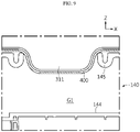
- the cover plate 145 covers the top of the upper cover groove 141a, and is coupled to the upper cover 141.
- the cover plate 145 has at least one pair of cover plate holes 145a, and is installed to be spaced apart from the fuse cover 144 so that a first grip groove G1 is formed between the cover plate 145 and the fuse cover 144.
- the cover plate hole 145a and the first grip groove G1 provide a space for a worker to grip the battery module 100 by inserting a finger or a gripping device when transporting the battery module 100, thereby giving convenience in transporting the battery module 100.
- the cover plate hole 145a and the first grip groove G1 provide an insertion space for the guide protrusion 311 (see FIG. 8 ) provided on the BMS assembly 300 as described above in addition to the above function, thereby guiding the coupling between the BMS assembly 300 and the battery module 100.
- the guide protrusion 311 has a size and shape corresponding to the cover plate hole 145a, thereby preventing the gas and/or flame generated from the cell stack 110 located at a lower portion of the upper cover assembly 140 from being leaked toward the BMS assembly 300 through the upper portion of the battery module 100.
- a gasket 400 may be interposed between the guide protrusion 311 and the inner surface of the cover plate hole 145a. This is to further increase airtightness in order to more reliably prevent the gas and/or flame generated from the cell stack 110 from being leaked toward the BMS assembly 300 through the upper portion of the battery module 100.
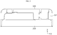
- the BMS assembly 300 includes a BMS body 310 and a BMS cover 320.
- the BMS body 310 includes at least one BMS, and has at least two second connectors C2 provided at a lower surface thereof and electrically connected to the BMS.
- Each second connector C2 is coupled with the first connector C1 provided on the top of the plurality of battery modules 100 in one-to-one relationship, and thus each battery module 100 is electrically connected to the BMS.
- the battery modules 100 may be electrically connected to each other in series and/or in parallel.
- the BMS cover 320 is coupled to the upper portion of the BMS body 310.
- the BMS cover 320 may function as a handle of the BMS assembly 300. That is, one side and the other side of the BMS cover 320 in the longitudinal direction (a direction parallel to the X axis in FIG. 5 ) and the upper surface of the BMS body 310 are spaced apart from each other by a predetermined distance, and accordingly, second grip grooves G2 are formed at both longitudinal sides of the BMS cover 320, respectively.
- the second grip groove G2 gives a space for a worker to insert a finger or a gripping device to move the BMS assembly 300 and/or transport the battery pack 1.
- a structure capable of smoothly discharging the gas generated from the cell stack 110 to the outside and preventing the flame from being discharged to the outside is formed at the bottom of the battery module 100.
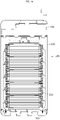
- the lower cover 130 includes a pair of lower cover holes 130a formed at both sides thereof in the longitudinal direction (a direction parallel to the X axis in FIG. 11 ) and a plurality of first partition walls 131.
- the lower cover 130 may further include a pair of mesh filters M.
- the lower cover hole 130a communicates with a gas channel P formed between the cell stack 110 and the module housing 120. Accordingly, the gas and/or flame generated from the cell stack 110 may be discharged downward (in a direction parallel to the Z axis of FIG. 11 ) through the lower cover hole 130a.
- the mesh filter M is inserted/fixed in the lower cover hole 130a.
- the mesh filter M allows the gas generated in the battery module 100 to pass as it is, but reduces the amount of flame discharged downward through the lower cover hole 130a and the speed of flame ejection.
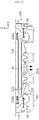
- the first partition wall 131 has a shape extending downward from the lower surface of the lower cover 130 and is spaced apart from the upper surface of the supporting plate 200 so that gas may move along the arrow.
- the first partition wall 131 increases a movement path of the flame together with a second partition wall 210, explained later, so that the flame may be extinguished inside the battery pack 1 without being leaked to the outside.
- the supporting plate 200 is positioned under the plurality of battery modules 100 and provides a space into which the plurality of battery modules 100 may be inserted.
- the supporting plate 200 includes a plurality of second partition walls 210 formed to extend upward (in a direction parallel to the Z axis in FIG. 11 ) and a gas discharge hole 200a formed at a center thereof in a longitudinal direction (a direction parallel to the X axis in FIG. 11 ).
- the plurality of second partition walls 210 are spaced apart from a lower surface of the battery module 100, namely a lower surface of the lower cover 130, so that gas may move along the arrow.
- the first partition wall 131 and the second partition wall 210 formed at positions corresponding to each other are overlap each other. That is, the supporting plate 200 is coupled to a bottom of the pair of battery module 100 so that the plurality of first partition walls 131 and the plurality of second partition walls 210 are adjacent and overlap each other in one-to-one pairs. Therefore, the flame introduced into the space between the lower cover 130 and the supporting plate 200 through the mesh filter M increases its movement path when it moves toward the gas discharge hole 200a, and accordingly, the flame may be extinguished without being discharged to the outside through the gas discharge hole 200a. That is, the supporting plate 200 serves as a component for fixing the battery module 100 and a component for giving a structure for extinguishing the flame simultaneously.
- a mesh filter M may be inserted into the gas discharge hole 200a. That is, the mesh filter M may be installed in at least one of the lower cover hole 130a of the lower cover 130 and the gas discharge hole 200a of the supporting plate 200. If the mesh filter (M) is mounted in both places, it is possible to further reduce the risk of the flame leaking out of the battery pack 1.
- At least a part of the plurality of second partition walls 210 may be in contact with the lower surface of the battery module 100, namely the lower surface of the lower cover 130.
- a partition wall hole 210a is formed in the second partition wall 210 in contact with the lower surface of the lower cover 130 to allow gas to move along the arrow. If at least a part of the plurality of second partition walls 210 is in contact with the lower surface of the lower cover 130 as above, the contact area between the lower cover 130 and the supporting plate 200 is increased, thereby improving structural rigidity.
- an ESS includes at least one battery pack 1 according to the present disclosure as described above.
Landscapes
- Chemical & Material Sciences (AREA)
- Chemical Kinetics & Catalysis (AREA)
- Electrochemistry (AREA)
- General Chemical & Material Sciences (AREA)
- Engineering & Computer Science (AREA)
- Manufacturing & Machinery (AREA)
- Microelectronics & Electronic Packaging (AREA)
- Battery Mounting, Suspending (AREA)
- Connection Of Batteries Or Terminals (AREA)
- Gas Exhaust Devices For Batteries (AREA)
Applications Claiming Priority (2)
| Application Number | Priority Date | Filing Date | Title |
|---|---|---|---|
| KR1020200034081A KR102829076B1 (ko) | 2020-03-19 | 2020-03-19 | 이동 및 조립의 편의성이 증대된 구조 및 안전성이 향상된 구조를 갖는 배터리 팩, 및 이를 포함하는 ess |
| PCT/KR2021/003047 WO2021187806A1 (ko) | 2020-03-19 | 2021-03-11 | 이동 및 조립의 편의성이 증대된 구조 및 안전성이 향상된 구조를 갖는 배터리 팩, 및 이를 포함하는 ess |
Publications (2)
| Publication Number | Publication Date |
|---|---|
| EP4037085A1 true EP4037085A1 (de) | 2022-08-03 |
| EP4037085A4 EP4037085A4 (de) | 2024-01-24 |
Family
ID=77771338
Family Applications (1)
| Application Number | Title | Priority Date | Filing Date |
|---|---|---|---|
| EP21772158.8A Pending EP4037085A4 (de) | 2020-03-19 | 2021-03-11 | Batteriepack, das eine struktur mit erhöhter beweglichkeit und einfachem zusammensetzen und eine struktur mit verbesserter sicherheit aufweist, sowie ess damit |
Country Status (6)
| Country | Link |
|---|---|
| US (1) | US12476323B2 (de) |
| EP (1) | EP4037085A4 (de) |
| JP (1) | JP7345574B2 (de) |
| KR (1) | KR102829076B1 (de) |
| CN (1) | CN114342163B (de) |
| WO (1) | WO2021187806A1 (de) |
Families Citing this family (11)
| Publication number | Priority date | Publication date | Assignee | Title |
|---|---|---|---|---|
| KR102812829B1 (ko) * | 2020-03-05 | 2025-05-23 | 주식회사 엘지에너지솔루션 | 이동 및 조립이 편의성이 증대된 구조 및 안전성이 향상된 구조를 갖는 배터리 팩 |
| USD1033334S1 (en) * | 2021-01-04 | 2024-07-02 | Lg Energy Solution, Ltd. | Battery pack |
| DE102021125191A1 (de) | 2021-09-29 | 2023-03-30 | Audi Aktiengesellschaft | Batterieanordnung mit einem Zellentgasungskanal, Kraftfahrzeug und Verfahren zum Abführen von Gasen aus einer Batterie |
| WO2023069415A1 (en) * | 2021-10-19 | 2023-04-27 | Cadenza Innovation, Inc. | Battery systems with pouch cells |
| KR20230100621A (ko) * | 2021-12-28 | 2023-07-05 | 주식회사 엘지에너지솔루션 | 소화수 저장 탱크를 구비한 배터리 팩 |
| CN216720171U (zh) * | 2022-01-14 | 2022-06-10 | 宁德时代新能源科技股份有限公司 | 储能集装箱 |
| KR102732262B1 (ko) * | 2022-01-20 | 2024-11-20 | 에스케이온 주식회사 | 배터리 모듈 및 이를 구비하는 배터리 팩 |
| EP4383428A4 (de) * | 2022-07-20 | 2025-06-18 | LG Energy Solution, Ltd. | Batterieanordnung sowie batteriepack und fahrzeug damit |
| EP4550555A4 (de) * | 2022-12-23 | 2025-08-13 | Lg Energy Solution Ltd | Batteriepack |
| KR20250147782A (ko) * | 2024-03-28 | 2025-10-14 | 주식회사 엘지에너지솔루션 | 배터리 팩 |
| CN222168611U (zh) * | 2024-04-03 | 2024-12-13 | 惠州亿纬锂能股份有限公司 | 一种电池模组 |
Family Cites Families (25)
| Publication number | Priority date | Publication date | Assignee | Title |
|---|---|---|---|---|
| JP2007027011A (ja) * | 2005-07-20 | 2007-02-01 | Sanyo Electric Co Ltd | 電源装置 |
| US7964300B2 (en) * | 2005-09-30 | 2011-06-21 | Tdk-Lambda Corporation | Battery pack |
| WO2012073454A1 (ja) | 2010-11-30 | 2012-06-07 | パナソニック株式会社 | 電池パック |
| JP5726605B2 (ja) * | 2011-04-12 | 2015-06-03 | 日立オートモティブシステムズ株式会社 | 組電池を内蔵した電池ブロックおよび蓄電装置 |
| US9472797B2 (en) | 2011-05-25 | 2016-10-18 | Samsung Sdi Co., Ltd. | Battery pack |
| JP5974520B2 (ja) * | 2012-02-08 | 2016-08-23 | 株式会社Gsユアサ | 蓄電デバイス及び蓄電モジュール |
| JP2013181735A (ja) | 2012-03-05 | 2013-09-12 | Yazaki Energy System Corp | 集熱器 |
| JP2015118811A (ja) | 2013-12-18 | 2015-06-25 | 日産自動車株式会社 | 二次電池 |
| JP6355347B2 (ja) | 2014-01-30 | 2018-07-11 | 日立建機株式会社 | ハイブリッド式建設機械 |
| JPWO2016199558A1 (ja) | 2015-06-12 | 2018-03-29 | 株式会社Gsユアサ | 蓄電装置 |
| KR101935013B1 (ko) * | 2015-09-25 | 2019-01-03 | 주식회사 엘지화학 | 배터리 모듈, 이러한 배터리 모듈을 포함하는 배터리 팩 및 이러한 배터리 팩을 포함하는 자동차 |
| KR102030726B1 (ko) | 2015-10-15 | 2019-10-10 | 주식회사 엘지화학 | 배터리 팩 |
| KR102065096B1 (ko) * | 2016-02-12 | 2020-01-10 | 주식회사 엘지화학 | 배터리 팩 |
| KR102292303B1 (ko) * | 2016-06-17 | 2021-08-20 | 에스케이이노베이션 주식회사 | 이차 전지 팩 |
| KR20180006150A (ko) * | 2016-07-08 | 2018-01-17 | 주식회사 엘지화학 | 안전성이 개선된 셀 모듈 어셈블리 및 이를 위한 팩 구조물 |
| CN106374070B (zh) * | 2016-09-28 | 2019-04-23 | 广东晓兰客车有限公司 | 一种新能源汽车用锂电池自动调节缓冲通风装置 |
| KR102133554B1 (ko) * | 2016-10-21 | 2020-07-13 | 주식회사 엘지화학 | 배터리 팩 |
| KR102256596B1 (ko) | 2017-04-07 | 2021-06-02 | 주식회사 엘지에너지솔루션 | 배터리 팩 및 이러한 배터리 팩을 포함하는 자동차 |
| JP2018195745A (ja) | 2017-05-19 | 2018-12-06 | 株式会社フジクラ | 蓄電モジュール |
| KR102033101B1 (ko) * | 2017-09-27 | 2019-10-16 | 주식회사 엘지화학 | 배터리 모듈, 이를 포함하는 배터리 팩 및 자동차 |
| WO2020039722A1 (ja) * | 2018-08-23 | 2020-02-27 | パナソニックIpマネジメント株式会社 | 電池モジュール |
| KR102659731B1 (ko) | 2018-09-20 | 2024-04-23 | 삼성디스플레이 주식회사 | 표시장치 |
| CN209607808U (zh) | 2019-04-28 | 2019-11-08 | 苏州宏亮电子有限公司 | 一种电池用带有屏蔽功能的壳体 |
| CN210040454U (zh) | 2019-06-06 | 2020-02-07 | 苏州德博新能源有限公司 | 一种户用储能锂电池装置 |
| KR102812829B1 (ko) * | 2020-03-05 | 2025-05-23 | 주식회사 엘지에너지솔루션 | 이동 및 조립이 편의성이 증대된 구조 및 안전성이 향상된 구조를 갖는 배터리 팩 |
-
2020
- 2020-03-19 KR KR1020200034081A patent/KR102829076B1/ko active Active
-
2021
- 2021-03-11 US US17/796,775 patent/US12476323B2/en active Active
- 2021-03-11 EP EP21772158.8A patent/EP4037085A4/de active Pending
- 2021-03-11 JP JP2021576693A patent/JP7345574B2/ja active Active
- 2021-03-11 WO PCT/KR2021/003047 patent/WO2021187806A1/ko not_active Ceased
- 2021-03-11 CN CN202180005186.8A patent/CN114342163B/zh active Active
Also Published As
| Publication number | Publication date |
|---|---|
| CN114342163B (zh) | 2025-03-14 |
| CN114342163A (zh) | 2022-04-12 |
| US12476323B2 (en) | 2025-11-18 |
| JP2022539718A (ja) | 2022-09-13 |
| WO2021187806A1 (ko) | 2021-09-23 |
| KR102829076B1 (ko) | 2025-07-02 |
| EP4037085A4 (de) | 2024-01-24 |
| JP7345574B2 (ja) | 2023-09-15 |
| KR20210117632A (ko) | 2021-09-29 |
| US20230083113A1 (en) | 2023-03-16 |
Similar Documents
| Publication | Publication Date | Title |
|---|---|---|
| US12476323B2 (en) | Battery pack having structure with increased movement and ease of assembly and structure with improved safety, and ESS comprising same | |
| US12463261B2 (en) | Battery pack having structure with increased ease of movement and assembly, and structure with improved safety | |
| EP4142029A1 (de) | Batteriemodul mit struktur zur absorption von zellquellung sowie batteriepack und fahrzeug damit | |
| KR102851944B1 (ko) | 화염 배출 방지 구조를 갖는 배터리 모듈 및 이를 포함하는 배터리 팩, 그리고 이를 포함하는 자동차 및 ess | |
| KR102885905B1 (ko) | 화염 배출 방지 구조를 갖는 배터리 모듈, 그리고 이를 포함하는 배터리 팩 및 ess | |
| JP2025521234A (ja) | ガスベントパスを備えるバッテリーパック | |
| KR102943826B1 (ko) | 배터리 팩, 이를 포함하는 에너지 저장 장치 및 자동차 | |
| KR20240102774A (ko) | 배터리 모듈 및 이를 포함하는 배터리 팩 및 차량 | |
| KR101893961B1 (ko) | 배터리팩 | |
| EP4418434B1 (de) | Batteriemodul und batteriepack sowie fahrzeug damit | |
| EP4462558B1 (de) | Batteriepack | |
| KR20240030988A (ko) | 배터리 팩 및 이를 포함하는 차량 | |
| EP4657636A1 (de) | Batteriepack und fahrzeug damit | |
| EP4475308A1 (de) | Batteriepack und fahrzeug damit | |
| EP4668454A1 (de) | Batteriepack und fahrzeug damit | |
| EP4654365A1 (de) | Batteriepack und fahrzeug damit | |
| KR102960544B1 (ko) | 배터리 팩, 이를 포함하는 에너지 저장 장치 및 자동차 | |
| EP4738590A1 (de) | Batteriemodul und batteriepack sowie fahrzeug damit | |
| EP4651286A1 (de) | Batteriemodul und batteriepack sowie fahrzeug damit | |
| CN118648175A (zh) | 电池模块以及包括该电池模块的电池组和车辆 | |
| KR20230168123A (ko) | 배터리 팩 | |
| KR20260029232A (ko) | 배터리 유닛 | |
| EP4708511A1 (de) | Batteriepack und fahrzeug damit | |
| EP4708533A1 (de) | Batteriemodul und batteriepack sowie fahrzeug damit |
Legal Events
| Date | Code | Title | Description |
|---|---|---|---|
| STAA | Information on the status of an ep patent application or granted ep patent |
Free format text: STATUS: THE INTERNATIONAL PUBLICATION HAS BEEN MADE |
|
| PUAI | Public reference made under article 153(3) epc to a published international application that has entered the european phase |
Free format text: ORIGINAL CODE: 0009012 |
|
| STAA | Information on the status of an ep patent application or granted ep patent |
Free format text: STATUS: REQUEST FOR EXAMINATION WAS MADE |
|
| 17P | Request for examination filed |
Effective date: 20220429 |
|
| AK | Designated contracting states |
Kind code of ref document: A1 Designated state(s): AL AT BE BG CH CY CZ DE DK EE ES FI FR GB GR HR HU IE IS IT LI LT LU LV MC MK MT NL NO PL PT RO RS SE SI SK SM TR |
|
| DAV | Request for validation of the european patent (deleted) | ||
| DAX | Request for extension of the european patent (deleted) | ||
| RAP1 | Party data changed (applicant data changed or rights of an application transferred) |
Owner name: OMRON CORPORATION Owner name: LG ENERGY SOLUTION, LTD. |
|
| A4 | Supplementary search report drawn up and despatched |
Effective date: 20240102 |
|
| RIC1 | Information provided on ipc code assigned before grant |
Ipc: H01M 50/583 20210101ALI20231219BHEP Ipc: H01M 50/367 20210101ALI20231219BHEP Ipc: H01M 50/291 20210101ALI20231219BHEP Ipc: H01M 50/271 20210101ALI20231219BHEP Ipc: H01M 50/211 20210101ALI20231219BHEP Ipc: H01M 10/42 20060101ALI20231219BHEP Ipc: H01M 50/581 20210101ALI20231219BHEP Ipc: H01M 50/20 20210101ALI20231219BHEP Ipc: H01M 50/35 20210101AFI20231219BHEP |