EP4037151A1 - Statorstanzteil, statorkern und motor - Google Patents
Statorstanzteil, statorkern und motor Download PDFInfo
- Publication number
- EP4037151A1 EP4037151A1 EP22151331.0A EP22151331A EP4037151A1 EP 4037151 A1 EP4037151 A1 EP 4037151A1 EP 22151331 A EP22151331 A EP 22151331A EP 4037151 A1 EP4037151 A1 EP 4037151A1
- Authority
- EP
- European Patent Office
- Prior art keywords
- stator punching
- motor
- stator
- punching piece
- stator core
- Prior art date
- Legal status (The legal status is an assumption and is not a legal conclusion. Google has not performed a legal analysis and makes no representation as to the accuracy of the status listed.)
- Withdrawn
Links
- 238000004080 punching Methods 0.000 title claims abstract description 52
- 239000002826 coolant Substances 0.000 claims abstract description 19
- 230000017525 heat dissipation Effects 0.000 claims abstract description 7
- XLYOFNOQVPJJNP-UHFFFAOYSA-N water Substances O XLYOFNOQVPJJNP-UHFFFAOYSA-N 0.000 claims description 5
- 238000010030 laminating Methods 0.000 claims description 3
- 239000000203 mixture Substances 0.000 claims description 3
- 230000000694 effects Effects 0.000 abstract description 6
- 238000004519 manufacturing process Methods 0.000 abstract description 3
- 238000001816 cooling Methods 0.000 description 13
- 238000013461 design Methods 0.000 description 12
- 238000010586 diagram Methods 0.000 description 6
- 238000000034 method Methods 0.000 description 6
- 230000008901 benefit Effects 0.000 description 4
- 230000006872 improvement Effects 0.000 description 3
- 230000008569 process Effects 0.000 description 3
- 238000011161 development Methods 0.000 description 2
- 230000009286 beneficial effect Effects 0.000 description 1
- 230000009194 climbing Effects 0.000 description 1
- 238000004891 communication Methods 0.000 description 1
- 238000009434 installation Methods 0.000 description 1
- 230000003993 interaction Effects 0.000 description 1
- 230000001788 irregular Effects 0.000 description 1
- 238000003475 lamination Methods 0.000 description 1
- 230000007774 longterm Effects 0.000 description 1
- 238000012986 modification Methods 0.000 description 1
- 230000004048 modification Effects 0.000 description 1
- 238000004088 simulation Methods 0.000 description 1
- 238000012795 verification Methods 0.000 description 1
Images

Classifications
-
- H—ELECTRICITY
- H02—GENERATION; CONVERSION OR DISTRIBUTION OF ELECTRIC POWER
- H02K—DYNAMO-ELECTRIC MACHINES
- H02K1/00—Details of the magnetic circuit
- H02K1/06—Details of the magnetic circuit characterised by the shape, form or construction
- H02K1/12—Stationary parts of the magnetic circuit
-
- H—ELECTRICITY
- H02—GENERATION; CONVERSION OR DISTRIBUTION OF ELECTRIC POWER
- H02K—DYNAMO-ELECTRIC MACHINES
- H02K1/00—Details of the magnetic circuit
- H02K1/06—Details of the magnetic circuit characterised by the shape, form or construction
- H02K1/12—Stationary parts of the magnetic circuit
- H02K1/20—Stationary parts of the magnetic circuit with channels or ducts for flow of cooling medium
-
- H—ELECTRICITY
- H02—GENERATION; CONVERSION OR DISTRIBUTION OF ELECTRIC POWER
- H02K—DYNAMO-ELECTRIC MACHINES
- H02K2213/00—Specific aspects, not otherwise provided for and not covered by codes H02K2201/00 - H02K2211/00
- H02K2213/03—Machines characterised by numerical values, ranges, mathematical expressions or similar information
-
- H—ELECTRICITY
- H02—GENERATION; CONVERSION OR DISTRIBUTION OF ELECTRIC POWER
- H02K—DYNAMO-ELECTRIC MACHINES
- H02K9/00—Arrangements for cooling or ventilating
- H02K9/19—Arrangements for cooling or ventilating for machines with closed casing and closed-circuit cooling using a liquid cooling medium, e.g. oil
Definitions
- the present disclosure belongs to the technical field of motor manufacturing, and particularly relates to a stator punching piece, stator core and motor.
- the rated power and rated torque of the motor are completely determined by the motor cooling design scheme.
- the motor manufacturers generally increase the rated power and rated torque of the motor through the cooling design scheme such as oil cooling design, water cooling design or mixed cooling design and cooling medium circulation path design.
- the conventional way to increase the rated power and rated torque of the motor is the design of the cooling medium and the design of the cooling medium circulation path.
- the room for increasing the rated power and rated torque of the motor is close to the limit.
- the present disclosure improves the structure of the stator core, and discloses a stator punching piece, stator core and motor that can improve the cooling efficiency of the motor, so as to overcome the above problems or at least partially solve the above problems.
- a stator punching piece formed by die stamping, wherein an outer circumference of the stator punching piece is provided with a continuous concave-convex structure extending in an axial direction of the stator punching piece for a cooling medium to flow therethrough, so as to increase an heat dissipation area of an outer circumference of a stator core composed of the stator punching pieces and improve a flow state of the cooling medium on the outer circumferential surface of the stator core, thereby increasing a rated power and rated torque of a motor.
- the concave-convex structure is a wave-shaped structure.
- the wave-shaped structure is a sine-shaped structure, a continuous rectangular structure, or a sine-rectangular hybrid structure.
- a vertical distance between a lowest point of the concave and a highest point of the convex is 0.1-5 mm.
- a vertical distance between a lowest point of the concave and a highest point of the convex is 2-4 mm.
- a number of lugs are provided on the outer circumference of the stator punching piece, and the lugs are provided or not provided with the concave-convex structure.
- stator core which is formed by laminating a number of the stator punching pieces described in any one of the above.
- the concave-convex structures of the stator punching pieces have a same structure, and their positions when laminated are same or different.
- Another aspect of the present disclosure provides a motor, the motor adopts the stator core according to claim 7 or 8, and the stator core can increase the rated power and rated torque of the motor by 5-10%.
- the cooling medium of the motor is oil or a mixture of oil and water.
- stator punching piece is formed by die stamping, changing the shape of the outer edge of the stator punching piece has no effect on the manufacturing cost of the motor. Without increasing the cost, the rated power and rated torque of the motor are increased by 5-10%, thereby obtaining unexpected increase in the rated power and rated torque of the motor.
- orientation or positional relationship indicated by the terms “upper”, “lower”, “front”, “rear”, “left”, “right”, “top”, “bottom”, “inner”, “outer”, etc. are orientation or positional relationship based on the drawings, which are merely for convenience of describing the present disclosure and simplifying the description, rather than indicating or implying that the device or component referred to must have a specific orientation, or must be constructed and operated with a specific orientation, they should not be construed as limiting the present disclosure.
- the terms “installation”, “connected”, “connection” , “fixed” and the like should be broadly understood, for example, it may be fixedly connected, or detachably connected, or integrally connected; it may also be mechanically connected, or electrically connected; it may also be directly connected, or indirectly connected through an intermediate element; it may also be the internal communication of two components or the interaction relationship between two components.
- installation e.g., it may be fixedly connected, or detachably connected, or integrally connected; it may also be mechanically connected, or electrically connected; it may also be directly connected, or indirectly connected through an intermediate element; it may also be the internal communication of two components or the interaction relationship between two components.
- FIG. 1 is a schematic diagram of a partial structure of a stator punching piece in the prior art.
- the conventional motor stator punching piece is generally formed by die stamping, and its outer circumference is a standard circle or a standard circle with on one or more lugs for installing the stator.
- the conventional motor stator punching piece do not use the entire area of the outer circumference of the stator punching piece for heat dissipation or cooling.
- an embodiment of the present disclosure proposes a new technical solution for cooling and heat dissipation of the stator core.
- the stator punching piece is also formed by die stamping. Its main technical concept is as follows. An outer circumference of the stator punching piece is provided with a continuous concave-convex structure for a cooling medium to flow therethrough. Especially, the cooling medium flows through the concaves, so that even if the cooling medium is air, the heat dissipation effect of the stator punching piece can be improved.
- the specific shape, structure, and quantity of the above concaves and convexes may not be specifically limited.
- the thickness and outer edge of the stator punching piece can be of any size, which may be specifically adjusted according to the overall design of the motor.
- the above concave-convex structure extends in the axial direction of the stator punching piece for the cooling medium to flow therethrough, so as to increase an heat dissipation area of an outer circumference of a stator core composed of the stator punching pieces, and at the same time, improve a flow state of the cooling medium on the outer circumferential surface of the stator core.
- the improved cooling performance can increase the rated power and rated torque of the motor.
- the above design can make the rated power and rated torque of the motor increase unexpectedly, and the increase is within the range of 5%-10%.
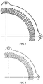
- the concave-convex structure is a wave-shaped structure.
- the wave-shaped structure is a sine-shaped structure, a continuous rectangular structure, or a sine-rectangular hybrid structure.
- the wave-shaped structure in FIG. 3 is of a hybrid type of sinusoidal wave and rectangular wave. Of course, it may also be any other regular or irregular shape.
- the quantity of sine wave peaks or valleys is more than five, so as to cover the entire area of the outer circumference of the stator punching piece.
- the range of the vertical distance H between the lowest point of the concave and the highest point of the convex is 0.1-5 mm.
- the sizes of the concaves and convexes are not limited by the above numerical range, and may be adjusted according to the overall design requirements of the motor.
- FIG.4 shows a schematic diagram of the vertical distance H between the peak and peak of the sinusoidal stator punching piece. The value of the vertical distance H in FIG. 4 is preferably 3 mm.
- the range of the vertical distance H between the lowest point of the concave and the highest point of the convex is 2-4 mm. This numerical range is a preferred range for improving the cooling efficiency of the motor, and technical effects better than normal are obtained.
- a number of lugs are provided on the outer circumference of the stator punching piece.
- the lugs may be used to fix the stator punching piece and the stator core composed of the stator punching pieces on the motor housing.
- the lugs may be provided or not provided with the concave-convex structure.
- a stator core is provided, which is formed by laminating a number of the above stator punching pieces.
- the concave-convex structures of the stator punching pieces of the same stator core have the same or similar structure, and their concave or convex positions during lamination are the same, so that the concaves on the stator core form a straight flow channel in the axial direction.
- the concave or convex positions on the stator punching pieces are slightly misaligned, thereby forming a curved or spiral cooling medium flow channel on the stator core.
- a motor is further provided, which uses any one of the above stator cores. Therefore, the application of the stator core can increase the rated power and rated torque of the motor by 5-10%, and thus unexpected technical effects are obtained through the above improvement on the structure of the stator punching piece.
- the cooling medium of the motor is oil or a mixture of oil and water, instead of a single form of water cooling.
Landscapes
- Engineering & Computer Science (AREA)
- Power Engineering (AREA)
- Iron Core Of Rotating Electric Machines (AREA)
- Motor Or Generator Cooling System (AREA)
Applications Claiming Priority (1)
| Application Number | Priority Date | Filing Date | Title |
|---|---|---|---|
| CN202110061453.5A CN112769256A (zh) | 2021-01-18 | 2021-01-18 | 一种定子冲片、定子铁芯和电机 |
Publications (1)
| Publication Number | Publication Date |
|---|---|
| EP4037151A1 true EP4037151A1 (de) | 2022-08-03 |
Family
ID=75702471
Family Applications (1)
| Application Number | Title | Priority Date | Filing Date |
|---|---|---|---|
| EP22151331.0A Withdrawn EP4037151A1 (de) | 2021-01-18 | 2022-01-13 | Statorstanzteil, statorkern und motor |
Country Status (4)
| Country | Link |
|---|---|
| US (1) | US20220231552A1 (de) |
| EP (1) | EP4037151A1 (de) |
| JP (1) | JP2022111092A (de) |
| CN (1) | CN112769256A (de) |
Citations (8)
| Publication number | Priority date | Publication date | Assignee | Title |
|---|---|---|---|---|
| FR22894E (fr) * | 1920-03-25 | 1921-09-05 | Georges Dromel | Ventilation et refroidissement rationnel des machines à courant alternatif |
| US4102040A (en) * | 1975-07-03 | 1978-07-25 | Societe Anonyme Pour L'equipement Electrique Des Vehicules S.E.V. Marchal | Method of manufacturing a curved component of a magnetic circuit |
| US5491371A (en) * | 1993-12-13 | 1996-02-13 | Able Corporation | Electrical machinery laminations cooling |
| JP2010081787A (ja) * | 2008-08-25 | 2010-04-08 | Suri-Ai:Kk | 集中巻きモータ |
| US20110250083A1 (en) * | 2008-10-28 | 2011-10-13 | Lg Electronics Inc. | Linear compressor |
| US20140117797A1 (en) * | 2011-05-24 | 2014-05-01 | Siemens Aktiengesellschaft | Dynamoelectric machine comprising a self-supporting housing |
| US10164507B2 (en) * | 2012-08-09 | 2018-12-25 | Julián Romero-Beltran | Single-phase shaded pole induction motor, convertible to permanent magnet motor |
| CN210111714U (zh) * | 2019-04-15 | 2020-02-21 | 比亚迪股份有限公司 | 铁芯冲片、定子铁芯和电机 |
Family Cites Families (9)
| Publication number | Priority date | Publication date | Assignee | Title |
|---|---|---|---|---|
| JPH1169721A (ja) * | 1997-08-07 | 1999-03-09 | Yaskawa Electric Corp | コア直冷式液冷モータのステータ |
| JP2006033916A (ja) * | 2004-07-12 | 2006-02-02 | Nissan Motor Co Ltd | 電動機の冷却装置 |
| US7791238B2 (en) * | 2005-07-25 | 2010-09-07 | Hamilton Sundstrand Corporation | Internal thermal management for motor driven machinery |
| US8053938B2 (en) * | 2007-11-09 | 2011-11-08 | Hamilton Sundstand Corporation | Enhanced motor cooling system |
| US8395287B2 (en) * | 2010-10-04 | 2013-03-12 | Remy Technologies, Llc | Coolant channels for electric machine stator |
| CN206628905U (zh) * | 2017-02-28 | 2017-11-10 | 上海申意汽车零部件有限公司 | 提高输出功率的汽车发电机定子铁芯 |
| JP6850219B2 (ja) * | 2017-07-19 | 2021-03-31 | 本田技研工業株式会社 | ステータコア |
| CN111509876B (zh) * | 2020-05-27 | 2025-04-25 | 精进电动科技股份有限公司 | 一种定子铁芯冷却结构及电机冷却系统 |
| CN216056491U (zh) * | 2021-01-18 | 2022-03-15 | 精进电动科技股份有限公司 | 一种定子冲片、定子铁芯和电机 |
-
2021
- 2021-01-18 CN CN202110061453.5A patent/CN112769256A/zh active Pending
-
2022
- 2022-01-13 EP EP22151331.0A patent/EP4037151A1/de not_active Withdrawn
- 2022-01-14 US US17/576,258 patent/US20220231552A1/en not_active Abandoned
- 2022-01-14 JP JP2022004467A patent/JP2022111092A/ja active Pending
Patent Citations (8)
| Publication number | Priority date | Publication date | Assignee | Title |
|---|---|---|---|---|
| FR22894E (fr) * | 1920-03-25 | 1921-09-05 | Georges Dromel | Ventilation et refroidissement rationnel des machines à courant alternatif |
| US4102040A (en) * | 1975-07-03 | 1978-07-25 | Societe Anonyme Pour L'equipement Electrique Des Vehicules S.E.V. Marchal | Method of manufacturing a curved component of a magnetic circuit |
| US5491371A (en) * | 1993-12-13 | 1996-02-13 | Able Corporation | Electrical machinery laminations cooling |
| JP2010081787A (ja) * | 2008-08-25 | 2010-04-08 | Suri-Ai:Kk | 集中巻きモータ |
| US20110250083A1 (en) * | 2008-10-28 | 2011-10-13 | Lg Electronics Inc. | Linear compressor |
| US20140117797A1 (en) * | 2011-05-24 | 2014-05-01 | Siemens Aktiengesellschaft | Dynamoelectric machine comprising a self-supporting housing |
| US10164507B2 (en) * | 2012-08-09 | 2018-12-25 | Julián Romero-Beltran | Single-phase shaded pole induction motor, convertible to permanent magnet motor |
| CN210111714U (zh) * | 2019-04-15 | 2020-02-21 | 比亚迪股份有限公司 | 铁芯冲片、定子铁芯和电机 |
Also Published As
| Publication number | Publication date |
|---|---|
| CN112769256A (zh) | 2021-05-07 |
| JP2022111092A (ja) | 2022-07-29 |
| US20220231552A1 (en) | 2022-07-21 |
Similar Documents
| Publication | Publication Date | Title |
|---|---|---|
| CN106130224A (zh) | 永磁调速汽车驱动电机 | |
| EP4037151A1 (de) | Statorstanzteil, statorkern und motor | |
| CN216056491U (zh) | 一种定子冲片、定子铁芯和电机 | |
| CN209462111U (zh) | 高起动转矩的无壳电机 | |
| CN221947932U (zh) | 定子冲片、定子、电机、动力系统和车辆 | |
| CN202798175U (zh) | 一种永磁直驱式无机壳风力发电机装置 | |
| CN208445366U (zh) | 一种电动机转子及三相异步电动机 | |
| CN201533202U (zh) | 一种铸铝转子冲片 | |
| CN217115761U (zh) | 转子结构、电机以及具有的电器 | |
| CN201478941U (zh) | 大功率交流永磁伺服电机定子的散热结构 | |
| CN220492712U (zh) | 一种节能空调压缩机的铝线电机定转子冲片 | |
| CN224053960U (zh) | 一种电机定子铁芯 | |
| CN208241551U (zh) | 电机及汽车 | |
| CN220653066U (zh) | 一种汽车起动机转子冲片 | |
| CN108880156B (zh) | 一种异步电容运行电机 | |
| CN223451699U (zh) | 一种油冷电机定子 | |
| CN223230950U (zh) | 一种运用于涡旋压缩机的单相电机的转子冲片 | |
| CN206743074U (zh) | 一种车用交流发电机 | |
| CN219856661U (zh) | 一种电机轮毂结构 | |
| CN224082419U (zh) | 电芯结构、电池及用电设备 | |
| CN206673800U (zh) | 一种车用交流发电机 | |
| CN219659495U (zh) | 转子冲片、转子、电机、压缩机和车辆 | |
| CN223639104U (zh) | 海上大功率半直驱风力发电机用定子铁芯 | |
| CN223181894U (zh) | 一种变频驱动永磁同步电机 | |
| CN222281731U (zh) | 一种便携式大功率电感器 |
Legal Events
| Date | Code | Title | Description |
|---|---|---|---|
| PUAI | Public reference made under article 153(3) epc to a published international application that has entered the european phase |
Free format text: ORIGINAL CODE: 0009012 |
|
| STAA | Information on the status of an ep patent application or granted ep patent |
Free format text: STATUS: REQUEST FOR EXAMINATION WAS MADE |
|
| STAA | Information on the status of an ep patent application or granted ep patent |
Free format text: STATUS: EXAMINATION IS IN PROGRESS |
|
| 17P | Request for examination filed |
Effective date: 20220113 |
|
| AK | Designated contracting states |
Kind code of ref document: A1 Designated state(s): AL AT BE BG CH CY CZ DE DK EE ES FI FR GB GR HR HU IE IS IT LI LT LU LV MC MK MT NL NO PL PT RO RS SE SI SK SM TR |
|
| 17Q | First examination report despatched |
Effective date: 20220713 |
|
| STAA | Information on the status of an ep patent application or granted ep patent |
Free format text: STATUS: THE APPLICATION IS DEEMED TO BE WITHDRAWN |
|
| 18D | Application deemed to be withdrawn |
Effective date: 20240831 |