EP4037312A1 - Procédé et appareil de conversion de signal d'image et dispositif terminal - Google Patents
Procédé et appareil de conversion de signal d'image et dispositif terminal Download PDFInfo
- Publication number
- EP4037312A1 EP4037312A1 EP20876760.8A EP20876760A EP4037312A1 EP 4037312 A1 EP4037312 A1 EP 4037312A1 EP 20876760 A EP20876760 A EP 20876760A EP 4037312 A1 EP4037312 A1 EP 4037312A1
- Authority
- EP
- European Patent Office
- Prior art keywords
- value
- image signal
- pixels
- source image
- luminance value
- Prior art date
- Legal status (The legal status is an assumption and is not a legal conclusion. Google has not performed a legal analysis and makes no representation as to the accuracy of the status listed.)
- Pending
Links
Images



Classifications
-
- H—ELECTRICITY
- H04—ELECTRIC COMMUNICATION TECHNIQUE
- H04N—PICTORIAL COMMUNICATION, e.g. TELEVISION
- H04N19/00—Methods or arrangements for coding, decoding, compressing or decompressing digital video signals
- H04N19/10—Methods or arrangements for coding, decoding, compressing or decompressing digital video signals using adaptive coding
- H04N19/102—Methods or arrangements for coding, decoding, compressing or decompressing digital video signals using adaptive coding characterised by the element, parameter or selection affected or controlled by the adaptive coding
- H04N19/124—Quantisation
- H04N19/126—Details of normalisation or weighting functions, e.g. normalisation matrices or variable uniform quantisers
-
- H—ELECTRICITY
- H04—ELECTRIC COMMUNICATION TECHNIQUE
- H04N—PICTORIAL COMMUNICATION, e.g. TELEVISION
- H04N9/00—Details of colour television systems
- H04N9/64—Circuits for processing colour signals
- H04N9/67—Circuits for processing colour signals for matrixing
-
- G—PHYSICS
- G06—COMPUTING OR CALCULATING; COUNTING
- G06T—IMAGE DATA PROCESSING OR GENERATION, IN GENERAL
- G06T5/00—Image enhancement or restoration
- G06T5/90—Dynamic range modification of images or parts thereof
- G06T5/92—Dynamic range modification of images or parts thereof based on global image properties
-
- G—PHYSICS
- G09—EDUCATION; CRYPTOGRAPHY; DISPLAY; ADVERTISING; SEALS
- G09G—ARRANGEMENTS OR CIRCUITS FOR CONTROL OF INDICATING DEVICES USING STATIC MEANS TO PRESENT VARIABLE INFORMATION
- G09G5/00—Control arrangements or circuits for visual indicators common to cathode-ray tube indicators and other visual indicators
- G09G5/003—Details of a display terminal, the details relating to the control arrangement of the display terminal and to the interfaces thereto
- G09G5/005—Adapting incoming signals to the display format of the display terminal
-
- H—ELECTRICITY
- H04—ELECTRIC COMMUNICATION TECHNIQUE
- H04N—PICTORIAL COMMUNICATION, e.g. TELEVISION
- H04N19/00—Methods or arrangements for coding, decoding, compressing or decompressing digital video signals
- H04N19/10—Methods or arrangements for coding, decoding, compressing or decompressing digital video signals using adaptive coding
- H04N19/134—Methods or arrangements for coding, decoding, compressing or decompressing digital video signals using adaptive coding characterised by the element, parameter or criterion affecting or controlling the adaptive coding
- H04N19/136—Incoming video signal characteristics or properties
-
- H—ELECTRICITY
- H04—ELECTRIC COMMUNICATION TECHNIQUE
- H04N—PICTORIAL COMMUNICATION, e.g. TELEVISION
- H04N19/00—Methods or arrangements for coding, decoding, compressing or decompressing digital video signals
- H04N19/10—Methods or arrangements for coding, decoding, compressing or decompressing digital video signals using adaptive coding
- H04N19/169—Methods or arrangements for coding, decoding, compressing or decompressing digital video signals using adaptive coding characterised by the coding unit, i.e. the structural portion or semantic portion of the video signal being the object or the subject of the adaptive coding
- H04N19/17—Methods or arrangements for coding, decoding, compressing or decompressing digital video signals using adaptive coding characterised by the coding unit, i.e. the structural portion or semantic portion of the video signal being the object or the subject of the adaptive coding the unit being an image region, e.g. an object
- H04N19/172—Methods or arrangements for coding, decoding, compressing or decompressing digital video signals using adaptive coding characterised by the coding unit, i.e. the structural portion or semantic portion of the video signal being the object or the subject of the adaptive coding the unit being an image region, e.g. an object the region being a picture, frame or field
-
- H—ELECTRICITY
- H04—ELECTRIC COMMUNICATION TECHNIQUE
- H04N—PICTORIAL COMMUNICATION, e.g. TELEVISION
- H04N19/00—Methods or arrangements for coding, decoding, compressing or decompressing digital video signals
- H04N19/10—Methods or arrangements for coding, decoding, compressing or decompressing digital video signals using adaptive coding
- H04N19/169—Methods or arrangements for coding, decoding, compressing or decompressing digital video signals using adaptive coding characterised by the coding unit, i.e. the structural portion or semantic portion of the video signal being the object or the subject of the adaptive coding
- H04N19/186—Methods or arrangements for coding, decoding, compressing or decompressing digital video signals using adaptive coding characterised by the coding unit, i.e. the structural portion or semantic portion of the video signal being the object or the subject of the adaptive coding the unit being a colour or a chrominance component
-
- H—ELECTRICITY
- H04—ELECTRIC COMMUNICATION TECHNIQUE
- H04N—PICTORIAL COMMUNICATION, e.g. TELEVISION
- H04N19/00—Methods or arrangements for coding, decoding, compressing or decompressing digital video signals
- H04N19/10—Methods or arrangements for coding, decoding, compressing or decompressing digital video signals using adaptive coding
- H04N19/189—Methods or arrangements for coding, decoding, compressing or decompressing digital video signals using adaptive coding characterised by the adaptation method, adaptation tool or adaptation type used for the adaptive coding
-
- G—PHYSICS
- G06—COMPUTING OR CALCULATING; COUNTING
- G06T—IMAGE DATA PROCESSING OR GENERATION, IN GENERAL
- G06T2207/00—Indexing scheme for image analysis or image enhancement
- G06T2207/20—Special algorithmic details
- G06T2207/20172—Image enhancement details
- G06T2207/20208—High dynamic range [HDR] image processing
-
- G—PHYSICS
- G09—EDUCATION; CRYPTOGRAPHY; DISPLAY; ADVERTISING; SEALS
- G09G—ARRANGEMENTS OR CIRCUITS FOR CONTROL OF INDICATING DEVICES USING STATIC MEANS TO PRESENT VARIABLE INFORMATION
- G09G2320/00—Control of display operating conditions
- G09G2320/02—Improving the quality of display appearance
- G09G2320/0271—Adjustment of the gradation levels within the range of the gradation scale, e.g. by redistribution or clipping
-
- G—PHYSICS
- G09—EDUCATION; CRYPTOGRAPHY; DISPLAY; ADVERTISING; SEALS
- G09G—ARRANGEMENTS OR CIRCUITS FOR CONTROL OF INDICATING DEVICES USING STATIC MEANS TO PRESENT VARIABLE INFORMATION
- G09G2370/00—Aspects of data communication
- G09G2370/04—Exchange of auxiliary data, i.e. other than image data, between monitor and graphics controller
-
- G—PHYSICS
- G09—EDUCATION; CRYPTOGRAPHY; DISPLAY; ADVERTISING; SEALS
- G09G—ARRANGEMENTS OR CIRCUITS FOR CONTROL OF INDICATING DEVICES USING STATIC MEANS TO PRESENT VARIABLE INFORMATION
- G09G5/00—Control arrangements or circuits for visual indicators common to cathode-ray tube indicators and other visual indicators
- G09G5/02—Control arrangements or circuits for visual indicators common to cathode-ray tube indicators and other visual indicators characterised by the way in which colour is displayed
-
- G—PHYSICS
- G09—EDUCATION; CRYPTOGRAPHY; DISPLAY; ADVERTISING; SEALS
- G09G—ARRANGEMENTS OR CIRCUITS FOR CONTROL OF INDICATING DEVICES USING STATIC MEANS TO PRESENT VARIABLE INFORMATION
- G09G5/00—Control arrangements or circuits for visual indicators common to cathode-ray tube indicators and other visual indicators
- G09G5/10—Intensity circuits
-
- H—ELECTRICITY
- H04—ELECTRIC COMMUNICATION TECHNIQUE
- H04N—PICTORIAL COMMUNICATION, e.g. TELEVISION
- H04N1/00—Scanning, transmission or reproduction of documents or the like, e.g. facsimile transmission; Details thereof
- H04N1/46—Colour picture communication systems
- H04N1/56—Processing of colour picture signals
- H04N1/60—Colour correction or control
- H04N1/603—Colour correction or control controlled by characteristics of the picture signal generator or the picture reproducer
- H04N1/6052—Matching two or more picture signal generators or two or more picture reproducers
Definitions
- the present invention relates to the field of image processing technologies, and in particular, to a method and an apparatus for processing image signal conversion, and a terminal device.
- a dynamic range is a rate of a maximum grayscale value to a minimum grayscale value in a range in which the image can be displayed.
- a dynamic range of the real world may reach 10 7 , and is referred to as a high dynamic range (high dynamic range, HDR).
- HDR high dynamic range
- each of R, G, and B channels separately uses one 8-bit byte for storage.
- a representation range of each channel is a 0 to 255 gray scale.
- a dynamic range of a color digital image is 0 to 255, and is referred to as a low dynamic range (low dynamic range, LDR).
- LDR low dynamic range
- a typical HDR video processing process includes: pre-processing, encoding, decoding, and post-processing.
- An HDR video is input, and undergoes processing performed by an optical-electro transfer function, color space transfer, floating-point-to-fixed-point conversion, 4:4:4-to-4:2:0 downsampling, and encoding performed by a 4:2:0 encoder, and a bitstream is obtained.
- the bitstream undergoes decoding performed by a 4:2:0 decoder, 4:2:0-to-4:4:4 upsampling, fixed-point-to-floating-point conversion, color space transfer, and processing performed by an electro-optical transfer function, and a finally output HDR video is obtained.
- a transfer function is used to perform non-linear transfer on an HDR source.
- the HDR video finally needs to be quantized to data that has an integral number of bits, and then is encoded.
- a dynamic range of the HDR video is far greater than a dynamic range of the data that has an integral number of bits, if linear quantization is directly performed, information about the HDR source is severely damaged. Therefore, the transfer function is mainly used to protect, through the non-linear transfer, a luminance segment that requires key protection.
- a primary color signal is an optical signal in the real world, may be represented by "L” or "E”, usually records a numeric value that is corresponding to a specific color component (for example, R, G, B, or Y), and is generally proportional to light intensity.
- a primary color signal of the image may be expressed in real luminance (for example, 10000 nits), or may be expressed in normalized luminance, for example, on the basis that maximum luminance of 10000 nits is normalized to maximum luminance of 1.
- Processed image information obtained after the primary color signal undergoes conversion processing is a numeric expression value of the image, and a value of the processed image information is normalized to [0, 1].
- the value of the processed image information may be represented by " L' " or " E' ", and is usually used to represent a non-linear color value.
- Optical-electro transfer is performed on the primary color signal (normalized to [0, 1]) by using the optical-electro transfer function, to obtain processed image information.
- the processed image information obtained through the transfer performed by the optical-electro transfer function may include primary colors such as R, G, B, and Y.
- Electro-optical transfer is performed on input image information by using the electro-optical transfer function, to obtain an output primary color signal.
- the processed output primary color signal is a restored optical signal in the real world.
- the optical-electro transfer function OETF optical-electro transfer function
- the electro-optical transfer function EOTF electro-optical transfer function
- the floating-point-to-fixed-point conversion is sometimes referred to as quantization
- the fixed-point-to-floating-point conversion is sometimes referred to as dequantization.
- An optical-electro transfer function in a conventional technology is proposed based on a luminance perception model of a human eye.
- This application provides a method and an apparatus for processing image signal conversion, and a terminal device, to improve quality of mutual conversion between images in different dynamic ranges, to better adapt to a display device and obtain a displayed image of better quality.
- a first aspect of this application provides a method for processing image signal conversion.
- the model parameter is a rational number.
- This embodiment of this application provides a new dynamic range conversion model, so that a higher degree of freedom can be provided for matching richer image content.
- the model parameter is properly configured, so that quality of image dynamic range conversion can be improved.
- the method before the converting a first value of the primary color component into a second value based on a preset dynamic range conversion model, the method further includes: determining an obtaining manner of the model parameter based on identifier information carried in metadata, where the metadata includes static metadata and/or dynamic metadata.
- This embodiment of this application provides a plurality of obtaining manners of the model parameter, and a display end learns the plurality of obtaining manners of the model parameter by using the identifier information in the metadata, thereby providing a plurality of choices between different implementation complexity and effects.
- the metadata and the to-be-processed pixel are obtained by decoding a bitstream related to a source image signal.
- the obtaining manner of the model parameter includes: obtaining, through decoding, a value that is of the model parameter and that is carried in the metadata; using a preset value as a value of the model parameter; or obtaining a value of the model parameter through calculation based on information about the source image signal and/or information about a display device, where the information about the source image signal is obtained by decoding the metadata.
- this embodiment of this application provides three possible obtaining manners of the model parameter. It should be understood that respective values of a plurality of model parameters may be obtained in different manners, that is, different model parameters in one group of model parameters represented by a same identifier may be obtained in a same manner or different manners.
- At least one of k 1 , k 2 , k 3 , a, b, m, n, and p is obtained by obtaining, through decoding, the value that is of the model parameter and that is carried in the metadata.
- At least one of k 1 , k 2 , k 3 , m, and n is obtained based on the preset value, where 0 ⁇ n ⁇ 8, and 0 ⁇ m ⁇ 8.
- k 1 is 1.
- k 2 is 1.
- k 3 is 1.
- m is 2.4 or 1.
- n is 1 or 5/12.
- b is a minimum luminance value that is of the display device and that is obtained after normalization processing.
- k 3 is a maximum luminance value that is of pixels in a to-be-processed frame of the source image signal and that is obtained after normalization processing.
- the maximum luminance value of the pixels in the to-be-processed frame of the source image signal includes: a maximum value in luminance components of the pixels in the to-be-processed frame; or a maximum value in maximum primary color components of the pixels in the to-be-processed frame, where the maximum primary color component is a primary color component with a maximum value in a plurality of primary color components of one pixel.
- At least one of k 1 , k 2 , k 3 , a, b, m, n, and p is obtained through calculation based on the information about the source image signal and/or the information about the display device.
- the model parameter is obtained by using an attribute of the source image signal or the display device, so that performed dynamic range conversion processing more conforms to a feature of an actual application, and achieves a better effect.
- the following provides several specific implementations.
- TPL is 0.5
- TPH is 0.8
- p valueL is 3.5
- p valueH is 5.0
- g(x) x, where x is a rational number in the interval from 0 to 1.
- the average luminance value of the pixels in the to-be-processed frame of the source image signal includes: an average value of the luminance components of the pixels in the to-be-processed frame; or an average value of the maximum primary color components of the pixels in the to-be-processed frame.
- the minimum luminance value of the pixels in the to-be-processed frame of the source image signal includes: a minimum value in the luminance components of the pixels in the to-be-processed frame; or a minimum value in the maximum primary color components of the pixels in the to-be-processed frame.
- L3 is MaxSource.
- LR is 0.8, 1, or 1.2.
- the preset luminance value is 5 nits
- the preset rate is 10%, 20%, or 30%.
- the perceived luminance value is obtained by decoding the metadata.
- a is a difference between the maximum luminance value that is of the display device and that is obtained after the normalization processing and the minimum luminance value that is of the display device and that is obtained after the normalization processing.
- c is 7, and d is 3.
- the normalization processing includes: a process of converting a to-be-normalized signal into a non-linear PQ signal value according to a process specified in the ST 2084 or 2014-SMPTE standard, or a process of converting a to-be-normalized signal into a non-linear HLG signal value according to a process specified in the Rec. 2100-ITU standard.
- the method further includes: obtaining, through decoding, the maximum luminance value of the pixels in the to-be-processed frame of the source image signal from the metadata; and correcting the maximum luminance value of the pixels in the to-be-processed frame of the source image signal; and correspondingly, that at least one of k 1 , k 2 , k 3 , a, b, m, n, and p is obtained through calculation based on the information about the source image signal and/or the information about the display device includes: at least one of k 1 , k 2 , k 3 , a, b, m, n, and p is obtained based on a corrected value of the maximum luminance value of the pixels in the to-be-processed frame of the source image signal.
- a second aspect of this application provides an apparatus for processing image signal conversion.
- the obtaining module before the converting a first value of the primary color component into a second value based on a preset dynamic range conversion model, is further configured to determine an obtaining manner of the model parameter based on identifier information carried in metadata, where the metadata includes static metadata and/or dynamic metadata.
- the metadata and the to-be-processed pixel are obtained by decoding a bitstream related to a source image signal.
- the obtaining manner of the model parameter includes: obtaining, through decoding, a value that is of the model parameter and that is carried in the metadata; using a preset value as a value of the model parameter; or obtaining a value of the model parameter through calculation based on information about the source image signal and/or information about a display device, where the information about the source image signal is obtained by decoding the metadata.
- At least one of k 1 , k 2 , k 3 , a, b, m, n, and p is obtained by obtaining, through decoding, the value that is of the model parameter and that is carried in the metadata.
- At least one of k 1 , k 2 , k 3 , m, and n is obtained based on the preset value, where 0 ⁇ n ⁇ 8, and 0 ⁇ m ⁇ 8.
- k 1 is 1.
- k 2 is 1.
- k 3 is 1.
- m is 2.4 or 1.
- n is 1 or 5/12.
- b is a minimum luminance value that is of the display device and that is obtained after normalization processing.
- k 3 is a maximum luminance value that is of pixels in a to-be-processed frame of the source image signal and that is obtained after normalization processing.
- the maximum luminance value of the pixels in the to-be-processed frame of the source image signal includes: a maximum value in luminance components of the pixels in the to-be-processed frame; or a maximum value in maximum primary color components of the pixels in the to-be-processed frame, where the maximum primary color component is a primary color component with a maximum value in a plurality of primary color components of one pixel.
- At least one of k 1 , k 2 , k 3 , a, b, m, n, and p is obtained through calculation based on the information about the source image signal and/or the information about the display device.
- TPL is 0.5
- TPH is 0.8
- p valueL is 3.5
- p valueH is 5.0
- g(x) x, where x is a rational number in the interval from 0 to 1.
- the average luminance value of the pixels in the to-be-processed frame of the source image signal includes: an average value of the luminance components of the pixels in the to-be-processed frame; or an average value of the maximum primary color components of the pixels in the to-be-processed frame.
- the minimum luminance value of the pixels in the to-be-processed frame of the source image signal includes: a minimum value in the luminance components of the pixels in the to-be-processed frame; or a minimum value in the maximum primary color components of the pixels in the to-be-processed frame.
- L3 is MaxSource.
- LR is 0.8, 1, or 1.2.
- the preset luminance value is 5 nits
- the preset rate is 10%, 20%, or 30%.
- the perceived luminance value is obtained by decoding the metadata.
- a is a difference between the maximum luminance value that is of the display device and that is obtained after the normalization processing and the minimum luminance value that is of the display device and that is obtained after the normalization processing.
- c is 7, and d is 3.
- J(x) is the proportion of the pixels whose luminance is less than x nits in the to-be-processed frame of the source image signal
- Tp is the value that is of 1 nit and that is obtained after the normalization processing
- Tq is Tp multiplied by a ratio of the maximum luminance value that is of the pixels in the to-be-processed frame of the source image signal and that is obtained after the normalization processing to the maximum value that is of the display device and that is obtained after the normalization processing.
- the normalization processing includes: a process of converting a to-be-normalized signal into a non-linear PQ signal value according to a process specified in the ST 2084 or 2014-SMPTE standard, or a process of converting a to-be-normalized signal into a non-linear HLG signal value according to a process specified in the Rec. 2100-ITU standard.
- the obtaining module is further configured to: obtain, through decoding, the maximum luminance value of the pixels in the to-be-processed frame of the source image signal from the metadata; and correct the maximum luminance value of the pixels in the to-be-processed frame of the source image signal; and correspondingly, that at least one of k 1 , k 2 , k 3 , a, b, m, n, and p is obtained through calculation based on the information about the source image signal and/or the information about the display device includes: at least one of k 1 , k 2 , k 3 , a, b, m, n, and p is obtained based on a corrected value of the maximum luminance value of the pixels in the to-be-processed frame of the source image signal.
- a third aspect of this application provides an image processing device, including: a nonvolatile memory and a processor that are coupled to each other.
- the processor invokes program code stored in the memory, to perform the method according to the first aspect.
- a fourth aspect of this application provides a computer-readable storage medium.
- the computer-readable storage medium stores a computer program.
- the computer program runs on a processor, the method according to the first aspect is implemented.
- Maximum luminance value (max_display_mastering_luminance) of a display device is a 16-bit unsigned integer, represents maximum display luminance of the display device, is in a unit of 1 cd/m 2 , and ranges from 1 cd/m 2 to 65535 cd/m 2 .
- Minimum luminance value (min_display_mastering_luminance) of the display device is a 16-bit unsigned integer, represents minimum display luminance of the display device, is in a unit of 0.0001 cd/m 2 , and ranges from 0.0001 cd/m 2 to 6.5535 cd/m 2 .
- a value of max_display_mastering_luminance should be greater than a value of min_display_mastering_luminance.
- Minimum value (minimum_maxrgb) in maximum primary color component values of pixels of a source image signal also referred to as minimum value in RGB component maximum values: Maximum values in RGB components of all pixels of a scene or a frame of picture are obtained, and a minimum value in these maximum values is obtained.
- Average value (average_maxrgb) of the maximum primary color component values of the pixels of the source image signal also referred to as average value of the RGB component maximum values: The maximum values in the RGB components of all the pixels of the scene or the frame of picture are obtained, and an average value of these maximum values is obtained.
- Maximum value (maximum_maxrgb) in the maximum primary color component values of the pixels of the source image signal also referred to as maximum value in the RGB component maximum values: The maximum values in the RGB components of all the pixels of the scene or the frame of picture are obtained, and a maximum value in these maximum values is obtained.
- Metadata The metadata records key information of an image in a video, a scene, or a frame.
- Static metadata (static metadata): The static metadata is metadata that does not change in a sequence.
- Dynamic metadata (dynamic metadata): The dynamic metadata is metadata that changes with an image or a scene.
- the PQ HDR video is an HDR video transmitted in a PQ format.
- HLG HDR video The HLG HDR video is an HDR video transmitted in an HLG format.
- HDR non-linear editing video The HDR non-linear editing video is a video processed by non-linear editing software.
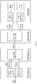
- FIG. 1 is a schematic diagram of a system for processing image signal conversion according to an embodiment of this application.
- an HDR end-to-end processing system is generally divided into four parts: HDR production, HDR transmission, HDR decoding, and HDR display.
- the HDR production includes editing an HDR material, performing color correction processing, outputting an HDR non-linear editing video, and extracting dynamic metadata of the HDR non-linear editing video through HDR pre-processing.
- the HDR transmission includes performing, according to a video compression standard (such as an AVS or HEVC standard), video encoding on the HDR non-linear editing video and the HDR dynamic metadata that are obtained after the HDR production, and outputting a corresponding bitstream (an AVS or HEVC bitstream).
- a video compression standard such as an AVS or HEVC standard
- the HDR decoding includes decoding the generated bitstream according to a standard corresponding to a bitstream format, and outputting an HDR decoded video and the HDR dynamic metadata.
- the HDR display is processing the HDR decoded video with reference to the HDR dynamic metadata and a target display terminal parameter (HDR adaptation processing), and displaying a processed HDR video (an HDR adapted video) on an HDR display terminal, where the target display terminal parameter is a luminance range of a target display terminal.
- the SDR display is processing the HDR video with reference to the HDR dynamic metadata and a target display terminal parameter (SDR adaptation processing), and displaying a processed HDR video (an SDR adapted video) on an SDR display terminal, where the target display terminal parameter is a luminance range of a target display terminal.
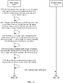
- FIG. 2A and FIG. 2B are a schematic flowchart of a method for processing image signal conversion according to an embodiment of this application. As shown in the figure, the method for processing image signal conversion in this embodiment of the present invention may at least include the following steps.
- a first terminal device performs optical-electro transfer on an input primary color signal by using a preset optical-electro transfer function, to obtain image information generated after optical-electro transfer.
- the terminal device may perform optical-electro transfer on the input primary color signal by using the preset optical-electro transfer function, to obtain the image information generated after optical-electro transfer.
- the terminal device may be a satellite, a personal computer (personal computer, PC), a smartphone, or the like.
- the first terminal device transfers, from RGB space to YCbCr space by using a preset first color space transfer function, the image information generated after optical-electro transfer, to obtain image information generated after space transfer.
- the first terminal device performs, in the YCbCr space, floating-point-to-fixed-point conversion on the image information generated after space transfer, to obtain image information generated after floating-point-to-fixed-point conversion.
- the first terminal device performs downsampling on the image information generated after floating-point-to-fixed-point conversion, to obtain image information generated after downsampling.
- the first terminal device encodes the image information generated after downsampling, to obtain encoded image information.
- the first terminal device sends the encoded image information to a second terminal device.
- the second terminal device decodes the encoded image information, to obtain decoded image information.
- the second terminal device performs upsampling on the decoded image information, to obtain image information generated after upsampling.
- the second terminal device performs fixed-point-to-floating-point conversion on the image information generated after upsampling, to obtain image information generated after fixed-point-to-floating-point conversion.
- the second terminal device transfers, from the YCbCr space to the RGB space by using a preset second color space transfer function, the image information generated after fixed-point-to-floating-point conversion, to obtain image information generated after space transfer.
- the second terminal device performs, by using a preset electro-optical transfer function, electro-optical transfer on the image information generated after space transfer, to obtain an output primary color signal.
- the second terminal device outputs the primary color signal.
- the first terminal device performs optical-electro transfer on the input primary color signal by using the preset optical-electro transfer function, to obtain the image information generated after optical-electro transfer; transfers, from the RGB space to the YCbCr space by using the preset first color space transfer function, the image information generated after optical-electro transfer, to obtain the image information generated after space transfer; performs, in the YCbCr space, floating-point-to-fixed-point conversion on the image information generated after space transfer, to obtain the image information generated after floating-point-to-fixed-point conversion; performs downsampling on the image information generated after floating-point-to-fixed-point conversion, to obtain the image information generated after downsampling; encodes the image information generated after downsampling; and sends the encoded image information to the second terminal device.
- the second terminal device decodes the encoded image information, to obtain the decoded image information; performs upsampling on the decoded image information, to obtain the image information generated after upsampling; performs fixed-point-to-floating-point conversion on the image information generated after upsampling, to obtain the image information generated after fixed-point-to-floating-point conversion; transfers, from the YCbCr space to the RGB space by using the preset second color space transfer function, the image information generated after fixed-point-to-floating-point conversion, to obtain the image information generated after space transfer; performs, by using the preset electro-optical transfer function, electro-optical transfer on the image information generated after space transfer, to obtain the output primary color signal; and outputs the primary color signal.
- quantization quality can be improved, and resource utilization can be improved.
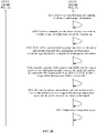
- FIG. 3 is a schematic flowchart of a method for processing image signal conversion according to another embodiment of this application.
- the method for processing image signal conversion in the embodiment shown in FIG. 3 may at least include the following steps.
- a terminal device performs optical-electro transfer on an input primary color signal by using a preset optical-electro transfer function, to obtain image information generated after optical-electro transfer.
- the terminal device may perform optical-electro transfer on the input primary color signal by using the preset optical-electro transfer function, to obtain the image information generated after optical-electro transfer.
- the terminal device may be a smartphone, a camera, a tablet computer, or the like. This image may be collected by the camera or stored locally in advance.
- the terminal device transfers, from RGB space to YCbCr space by using a preset first color space transfer function, the image information generated after optical-electro transfer, to obtain image information generated after space transfer.
- the terminal device performs, in the YCbCr space, floating-point-to-fixed-point conversion on the image information, to obtain image information generated after floating-point-to-fixed-point conversion.
- the terminal device performs downsampling on the image information generated after floating-point-to-fixed-point conversion, to obtain image information generated after downsampling.
- the terminal device performs upsampling on the image information generated after downsampling, to obtain image information generated after upsampling.
- the terminal device performs fixed-point-to-floating-point conversion on the image information generated after upsampling, to obtain image information generated after fixed-point-to-floating-point conversion.
- the terminal device transfers, from the YCbCr space to the RGB space by using a preset second color space transfer function, the image information generated after fixed-point-to-floating-point conversion, to obtain image information generated after space transfer.
- the terminal device performs, by using a preset electro-optical transfer function, electro-optical transfer on the image information generated after space transfer, to obtain an output primary color signal.
- the terminal device outputs the primary color signal.
- the terminal device performs optical-electro transfer on the input primary color signal by using the preset optical-electro transfer function, to obtain the image information generated after optical-electro transfer; transfers, from the RGB space to the YCbCr space by using the preset first color space transfer function, the image information generated after optical-electro transfer, to obtain the image information generated after space transfer; performs, in the YCbCr space, floating-point-to-fixed-point conversion on the image information generated after space transfer, to obtain the image information generated after floating-point-to-fixed-point conversion; performs downsampling on the image information generated after floating-point-to-fixed-point conversion, to obtain the image information generated after downsampling; performs upsampling on the image information generated after downsampling, to obtain the image information generated after upsampling; performs fixed-point-to-floating-point conversion on the image information generated after upsampling, to obtain the image information generated generated
- FIG. 2A and FIG. 2B and FIG. 3 an entire process of image signal conversion is described as an example in each of the methods for processing image signal conversion in FIG. 2A and FIG. 2B and FIG. 3 .
- This application mainly includes a dynamic range conversion module of an image signal and a corresponding processing method.
- the optical-electro transfer process and the optical-electro transfer function determining in the foregoing embodiments may be combined in another process for processing image signal conversion that includes the processes in FIG. 2A and FIG. 2B and FIG. 3 . This is not limited in this application.
- Dynamic range conversion is mainly applied to adaptation of a front-end HDR signal to a back-end HDR terminal display device.
- a luminance interval of a light signal collected by a front end is 4000 nits, but a display capability of a back-end HDR terminal display device (a television or an IPAD) is only 500 nits.
- Mapping the 4000-nit signal to the 500-nit display device is a process of dynamic range mapping (tone-mapping) from high to low.
- a luminance interval of an SDR signal (a standard dynamic range signal, falling within the foregoing LDR in comparison with HDR) collected by a front end is 100 nits, but a display end needs to display a 2000-nit television signal. Displaying the 100-nit signal on a 2000-nit display device is a process of tone-mapping from high to low.
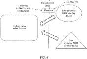
- FIG. 4 describes an example of a system architecture to which the embodiments of this application are applied.
- a front-end device including video collection and production devices
- completes production of high dynamic HDR content and transmits video source data (image information) and metadata (dynamic metadata and/or static metadata) to a display end by using a transmission layer.
- the display end converts, based on display capabilities (SDR or HDR) of different display devices, the received video source data (in some embodiments, in combination with information provided in the metadata) into a displayed image to which the display device adapts.
- SDR or HDR display capabilities
- a display device may have a display capability of a higher dynamic range than HDR content generated by a front end, and an adaption display process thereof may also be applied to the system architecture. This is not limited in this application.
- the dynamic range conversion module in the embodiments of this application may exist in a set-top box, a television display, a mobile terminal display, or a video conversion device of a network live broadcast, a network video application, or the like. More specifically, the module may exist in the set-top box, the television display, or the mobile terminal display in a chip form, or may exist in the video conversion device of the network live broadcast, the network video application, or the like in a software program form.
- FIG. 5 is a schematic flowchart of a method for processing image signal conversion according to another embodiment of this application.
- the method for processing image signal conversion in the embodiment shown in FIG. 5 may include at least the following steps.
- S501 Receive a bitstream that includes source image signal data and metadata.
- both the source image signal data (an HDR video signal) and the metadata are transmitted in a bitstream form.
- the bitstream is obtained by encoding image data and auxiliary information at a video content production end, and is restored to the source image signal data and the metadata in a lossy or lossless manner through decoding at a display end.
- the source image signal data may be pixel data
- the metadata may include a format of video source data and various parameters related to HDR video processing, such as parameters in a dynamic range conversion model.
- the source image signal data may be data in YUV color space or data in RGB color space; or may be 8-bit data, 10-bit data, or 12-bit data.
- a format of the metadata is not limited.
- the metadata may conform to the standard ST2094-40 and include histogram information and tone-mapping curve parameter information, or may conform to the standard ST2094-10 and include tone-mapping curve parameter information.
- the metadata may be dynamic metadata or static metadata, or may include both static metadata and dynamic metadata.
- the source image signal data received in this embodiment of this application may be an optical signal, or may be an electrical signal. This is not limited in this application.
- the obtaining manner of the model parameter is preset, that is, an obtaining manner of each model parameter is determined according to a protocol known by both an HDR production end and an HDR display end in advance.
- an obtaining manner of each model parameter may be adaptively determined based on information about the source image signal data, such as a distribution characteristic of luminance values in a luminance histogram.
- a plurality of obtaining manners may be predefined.
- the HDR production end writes a selected obtaining manner into identifier information of the metadata, and the HDR display end decodes the identifier information in the metadata to learn of the specific obtaining manner.
- the obtaining manner of the model parameter may include: obtaining, through decoding, a value that is of the model parameter and that is carried in the metadata, where the value of the model parameter is directly written into the metadata at the HDR production end; using a preset value as a value of the model parameter; or obtaining a value of the model parameter through calculation based on the information about the source image signal and/or information about a display device, where the information about the source image signal is obtained by decoding the metadata.
- the information about the source image signal may be directly included in the metadata as a syntax element, or the information about the source image signal may be obtained by first parsing a syntax element of the metadata and then performing derivation calculation based on a syntax element obtained after the parsing.
- the information about the source image signal includes a maximum luminance value of pixels in a to-be-processed frame of the source image signal, an average luminance value of the pixels in the to-be-processed frame of the source image signal, a minimum luminance value of the pixels in the to-be-processed frame of the source image signal, or the like.
- a corrected value is less than or equal to the maximum value of the actual pixels in the to-be-processed frame.
- a value may be set, so that a preset proportion of pixels whose luminance is greater than that of a darkest pixel and is less than the value in all the pixels is, for example, 99%, 95%, or 90%. The value is the corrected value.
- the corrected value may be alternatively set to the average value of all the pixels plus (luminance 1-luminance 2)/2, where the luminance 1 satisfies a case in which pixels whose luminance is greater than that of the darkest pixel and is less than the luminance 1 account for 90% of all the pixels, and the luminance 2 satisfies a case in which pixels whose luminance is greater than that of the darkest pixel and is less than the luminance 2 account for 10% of all the pixels.
- a corrected maximum luminance value of the pixels in the to-be-processed frame of the source image signal is referred to as the corrected value of the maximum luminance value of the pixels in the to-be-processed frame of the source image signal.
- the pixels in the to-be-processed frame may be all pixels in the to-be-processed frame, or may be effective pixels in the to-be-processed frame.
- the effective pixel is a pixel in a preset range of the source image signal, or a pixel in a range determined based on the metadata.
- the effective pixel may be a source image signal within a dark threshold and a bright threshold.
- the dark threshold may be a preset threshold.
- a preset proportion is set in the source image signal, so that the dark threshold satisfies a case in which pixels whose luminance is less than the dark threshold account for the preset proportion of all the pixels in the source image signal, to obtain the dark threshold, where the preset proportion may be 0%, 0.5%, 1%, 5%, 10%, or the like.
- the bright threshold may be a preset threshold.
- a preset proportion is set in the source image signal, so that the bright threshold satisfies a case in which pixels whose luminance is greater than the bright threshold account for the preset proportion of all the pixels in the source image signal, to obtain the bright threshold, where the preset proportion may be 0%, 0.5%, 1%, 5%, 10%, or the like.
- the identifier information may indicate a same obtaining manner jointly used by one group of model parameters, or may indicate a preset obtaining manner combination. In this combination, different model parameters may use a same obtaining manner or different obtaining manners.
- an image corresponding to the source image signal may include different areas, and different areas may have respective different model parameter obtaining manners, may have respective different model parameter values, or may have respective different conversion models. This is not limited.
- the image corresponding to the source image signal may include num_windows areas. For each area, one piece of identifier information tone_mapping_mode is decoded, to determine a model parameter obtaining manner in the area.
- tone_mapping_mode a relationship between a value of tone_mapping_mode and a number of to-be-determined model parameters may be as follows:
- a relationship between a value of tone_mapping_mode and a model parameter obtaining manner may be as follows:
- the obtaining process 1 includes: all parameters are set to preset values; and the obtaining process 2 includes: a first parameter is set to a preset value, a second parameter is obtained by parsing the metadata, and a third parameter is obtained through calculation based on the information that is about the source image signal and that is carried in the metadata, and the information about the display device.
- a dynamic range conversion model is applicable to pixels in all primary color value ranges. In some other embodiments, a dynamic range conversion model is applicable to pixels in only some primary color value ranges. Therefore, first, action intervals to which different dynamic range conversion models are applicable need to be determined, and a dynamic range conversion model is selected based on an action interval within which a to-be-processed pixel falls, to perform conversion. The determining of the action interval of the dynamic range conversion model in this embodiment of this application is not limited in this application.
- the to-be-processed pixel is obtained from the received source image signal data. It is assumed that the to-be-processed pixel satisfies the action interval of the dynamic range conversion model in this embodiment of this application.
- the to-be-processed pixel is in an RGB color domain, and a value of one of R, G, and B components is obtained.
- a value of a component with a maximum value in the R, G, and B components is obtained, and it is assumed that the value is denoted as Fmax.
- an obtaining manner of each model parameter may include the following cases:
- At least one of k 1 , k 2 , k 3 , a, b, m, n, and p is obtained by obtaining, through decoding, the value that is of the model parameter and that is carried in the metadata.
- values of all the model parameters are determined by the HDR production end, and the values are directly edited into the metadata and transmitted to the HDR display end.
- values of some parameters are determined based on preset values.
- At least one of k 1 , k 2 , and k 3 may be set to 1.
- m is a rational number greater than 0 and less than or equal to 8 (0 ⁇ m ⁇ 8). Specifically, m may be set to 2.4.
- n is a rational number greater than 0 and less than or equal to 8 (0 ⁇ n ⁇ 8). Specifically, n may be set to 1.
- n is set to 2.4 and n is set to 1; or m is set to 1 and n is set to 5/12 (for example, n is expressed to one decimal place, that is, 0.4).
- values of some parameters are obtained directly or through calculation based on the information that is about the source image signal and that is carried in the metadata, and/or the information about the display device.
- b may be a minimum luminance value that is of the display device and that is obtained after normalization processing.
- k 3 may be a maximum luminance value that is of the pixels in the to-be-processed frame of the source image signal and that is obtained after normalization processing.
- the normalization processing includes a process of converting a to-be-normalized signal into a non-linear PQ signal value according to a process specified in the ST 2084 or 2014-SMPTE standard (in some embodiments, a PQ(x) function is used to indicate that the normalization processing is performed on x), or a process of converting a to-be-normalized signal into a non-linear HLG signal value according to a process specified in the Rec. 2100-ITU standard (in some embodiments, an HLG(x) function is used to indicate that the normalization processing is performed on x).
- the maximum luminance value of the pixels in the to-be-processed frame of the source image signal may be a maximum value in luminance components of the pixels in the to-be-processed frame.
- the maximum luminance value is a maximum value in Y components.
- a luminance value may be obtained through calculation by using R, G, and B values.
- the maximum luminance value may be a maximum value in maximum primary color components of the pixels in the to-be-processed frame, where the maximum primary color component is a primary color component with a maximum value in a plurality of primary color components of one pixel, for example, a component with a maximum value in R, G, and B.
- an obtaining method of a luminance component in the minimum luminance value or the average luminance value of the pixels in the to-be-processed frame of the source image signal in the following is the same as the obtaining method of the luminance component in the maximum luminance value, and details are not described again.
- At least one of k 1 , k 2 , k 3 , a, b, m, n, and p is obtained through calculation based on the information about the source image signal and/or the information about the display device.
- the method further includes: obtaining, through decoding, the maximum luminance value of the pixels in the to-be-processed frame of the source image signal from the metadata; and before calculating a model parameter by using the maximum luminance value of the pixels in the to-be-processed frame of the source image signal, correcting the maximum luminance value of the pixels in the to-be-processed frame of the source image signal; and correspondingly, that at least one of k 1 , k 2 , k 3 , a, b, m, n, and p is obtained through calculation based on the information about the source image signal and/or the information about the display device includes: at least one of k 1 , k 2 , k 3 , a, b, m, n, and p is obtained based on a corrected value of the maximum luminance value of the pixels in the to-be-processed frame of the source image signal.
- a value obtaining process of each model parameter include the following:
- TPL is 0.5
- TPH is 0.8
- p valueL is 3.5
- p valueH is 5.0
- the information about the source image signal includes the average luminance value of the pixels in the to-be-processed frame of the source image signal, that is, avgL may be obtained by decoding the metadata.
- the average luminance value of the pixels in the to-be-processed frame of the source image signal includes: an average value of the luminance components of the pixels in the to-be-processed frame; or an average value of the maximum primary color components of the pixels in the to-be-processed frame.
- the information about the source image signal includes the maximum luminance value of the pixels in the to-be-processed frame of the source image signal and the minimum luminance value of the pixels in the to-be-processed frame of the source image signal, that is, MaxSource and MinSource may be obtained by decoding the metadata.
- MaxSource is the corrected value of the maximum luminance value that is of the pixels in the to-be-processed frame of the source image signal and that is obtained after the normalization processing.
- the minimum luminance value of the pixels in the to-be-processed frame of the source image signal includes: a minimum value in the luminance components of the pixels in the to-be-processed frame; or a minimum value in the maximum primary color components of the pixels in the to-be-processed frame.
- the maximum luminance value that is of the pixels in the to-be-processed frame of the source image signal and that is obtained after the normalization processing is also referred to as a maximum luminance value of the pixels in the to-be-processed frame of the source image signal in a PQ domain or a maximum luminance value of the pixels in the to-be-processed frame of the source image signal in an HLG domain.
- a physical quantity obtained after normalization processing also satisfies the same case, and details are not described below again.
- a value obtaining process of each model parameter include the following:
- the preset luminance value is 5 nits
- the preset rate is 10%, 20%, or 30%.
- J(x) may be obtained by collecting statistics on a cumulative histogram of the pixels in the to-be-processed frame of the source image signal.
- the perceived luminance value is obtained by decoding the metadata.
- L3 is the corrected value of the maximum luminance value that is of the pixels in the to-be-processed frame of the source image signal and that is obtained after the normalization processing.
- n is set to a preset value 1. It should be understood that, when any to-be-determined parameter in a, m, and p is learned in another manner, values of the other two unknown parameters may be obtained by solving only any two equations in the system of equations.
- the preset luminance value may be 2 nits, 5 nits, or the like.
- a value obtaining process of each model parameter include the following:
- v may be alternatively calculated in a different manner. Details are as follows:
- k 3 E src_max .
- the maximum luminance value ( E disp_max ) is a lower limit of a value of E src_max . This means that for a source image signal whose maximum luminance is lower than a maximum luminance value of a display device, tone mapping keeps the maximum luminance of the source image signal.
- p may be determined by using histogram information in the metadata, and a principle is that p is determined based on a tone loss caused by tone mapping.
- a theoretical basis of this method is a limitation of a human eye for contrast perception.
- a light adaptation threshold Tp approximately between 1 nit and 5 nits
- the light adaptation threshold varies from person to person.
- Tp is set to 1 nit by default, that is, it is assumed that the human eye can effectively perceive an image area whose luminance is higher than 1 nit, and contrast perception of the human eye for an area whose luminance is lower than 1 nit obviously decreases.
- the model parameter may be dynamically determined.
- values of p, n, and m may be determined by determining image scene luminance.
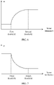
- FIG. 6 shows a relationship between image scene luminance and a parameter m.
- m is in direct proportion to the scene luminance, and larger scene luminance indicates a larger value of m.
- an upper bound of the first scene luminance range is a first threshold
- a lower bound of the first scene luminance range is a second threshold.
- a value of m is limited to a value that is of m and that is corresponding to the first threshold or the second threshold.
- n is determined based on luminance distribution in a luminance histogram of the scene luminance. Specifically, the luminance histogram may be produced based on the scene luminance.
- the parameters a and b may be calculated based on a maximum display capability of the display device, a minimum display capability of the display device, and a scene color range (or a mapped value of the scene color range) corresponding to a to-be-processed color signal.
- a display capability of the display device may be obtained based on a parameter of the display device or information of a manufacturer.
- the maximum display capability of the display device may approximately have several grades: 570 nits, 800 nits, and 1000 nits.
- the minimum display capability of the display device is usually 0 nits, or may be 1 nit.
- the scene color range including a color maximum value and a color minimum value of a scene, may be carried in the dynamic metadata.
- the color maximum value may be a maximum value in R, G, and B components.
- a proportion value of the maximum value (for example, 90% of the maximum value) may also be determined based on a weighted value (for example, an average value) of R, G, and B.
- the color minimum value may be 0, or may be determined based on the weighted value of R, G, and B.
- conversion of the first value into the second value may be completed based on the dynamic range conversion model.
- all primary color components of the to-be-processed pixel may be converted by using the method in step S505.
- only a primary color component with a maximum value in three primary color components of the to-be-processed pixel may be converted, and a rate of a denormalized second value to a denormalized first value is calculated. It is assumed that the rate is K.
- a value that is K times a denormalized value of each primary color component of the to-be-processed pixel is used as a converted value.
- one or more image processing processes such as saturation adjustment, color gamut conversion, denoising processing, and sharpening processing may be further performed on the converted image signal. This is not limited in this embodiment of this application.
- the parameter n is introduced into the dynamic range conversion model, and the parameter n may reflect a feature of luminance distribution in a scene corresponding to the to-be-processed color signal. This provides greater flexibility for adaptation between the dynamic range conversion model and the scene. When the other model parameters are properly configured, image content in different dynamic ranges is converted, so that a better display effect can be achieved.
- FIG. 8 is a schematic diagram of a structure of an apparatus for processing image signal conversion according to an embodiment of this application.
- the apparatus for processing image signal conversion provided in this embodiment of the present invention may be configured to implement some or all procedures in the embodiment of the method for processing image signal conversion described with reference to FIG. 2A and FIG. 2B , FIG. 3 , or FIG. 5 in the present invention.
- the obtaining module 801 before the converting a first value of the primary color component into a second value based on a preset dynamic range conversion model, is further configured to determine an obtaining manner of the model parameter based on identifier information carried in metadata, where the metadata includes static metadata and/or dynamic metadata.
- the metadata and the to-be-processed pixel are obtained by decoding a bitstream related to a source image signal.
- the obtaining manner of the model parameter includes: obtaining, through decoding, a value that is of the model parameter and that is carried in the metadata; using a preset value as a value of the model parameter; or obtaining a value of the model parameter through calculation based on information about the source image signal and/or information about a display device, where the information about the source image signal is obtained by decoding the metadata.
- At least one of k 1 , k 2 , k 3 , a, b, m, n, and p is obtained by obtaining, through decoding, the value that is of the model parameter and that is carried in the metadata.
- At least one of k 1 , k 2 , k 3 , m, and n is obtained based on the preset value, where 0 ⁇ n ⁇ 8, and 0 ⁇ m ⁇ 8.
- values of the model parameters satisfy at least one of the following: m is 2.4 or 1, n is 1 or 5/12, k 1 is 1, k 2 is 1, and k 3 is 1.
- b is a minimum luminance value that is of the display device and that is obtained after normalization processing.
- k 3 is a maximum luminance value that is of pixels in a to-be-processed frame of the source image signal and that is obtained after normalization processing.
- the maximum luminance value of the pixels in the to-be-processed frame of the source image signal includes: a maximum value in luminance components of the pixels in the to-be-processed frame; or a maximum value in maximum primary color components of the pixels in the to-be-processed frame, where the maximum primary color component is a primary color component with a maximum value in a plurality of primary color components of one pixel.
- At least one of k 1 , k 2 , k 3 , a, b, m, n, and p is obtained through calculation based on the information about the source image signal and/or the information about the display device.
- TPL is 0.5
- TPH is 0.8
- p valueL is 3.5
- p valueH is 5.0
- g(x) x, where x is a rational number in the interval from 0 to 1.
- the average luminance value of the pixels in the to-be-processed frame of the source image signal includes: an average value of the luminance components of the pixels in the to-be-processed frame; or an average value of the maximum primary color components of the pixels in the to-be-processed frame.
- the minimum luminance value of the pixels in the to-be-processed frame of the source image signal includes: a minimum value in the luminance components of the pixels in the to-be-processed frame; or a minimum value in the maximum primary color components of the pixels in the to-be-processed frame.
- LR is 0.8, 1, or 1.2.
- the preset luminance value is 5 nits
- the preset rate is 10%, 20%, or 30%.
- the perceived luminance value is obtained by decoding the metadata.
- a is a difference between the maximum luminance value that is of the display device and that is obtained after the normalization processing and the minimum luminance value that is of the display device and that is obtained after the normalization processing.
- c is 7, and d is 3.
- the normalization processing includes: a process of converting a to-be-normalized signal into a non-linear PQ signal value according to a process specified in the ST 2084 or 2014-SMPTE standard, or a process of converting a to-be-normalized signal into a non-linear HLG signal value according to a process specified in the Rec. 2100-ITU standard.
- the obtaining module 801 is further configured to: obtain, through decoding, the maximum luminance value of the pixels in the to-be-processed frame of the source image signal from the metadata; and correct the maximum luminance value of the pixels in the to-be-processed frame of the source image signal; and correspondingly, that at least one of k 1 , k 2 , k 3 , a, b, m, n, and p is obtained through calculation based on the information about the source image signal and/or the information about the display device includes: at least one of k 1 , k 2 , k 3 , a, b, m, n, and p is obtained based on a corrected value of the maximum luminance value of the pixels in the to-be-processed frame of the source image signal.
- FIG. 9 is a schematic diagram of a structure of a terminal device according to an embodiment of this application.
- a terminal device 900 may include a processor 901, a memory 902, an input apparatus 903, and an output apparatus 904.
- the processor 901 is connected to the memory 902, the input apparatus 903, and the output apparatus 904.
- the processor 901 may be connected to the memory 902, the input apparatus 903, and the output apparatus 904 by using a bus.
- the processor 901 may be a central processing unit (central processing unit, CPU), a network processor (network processor, NP), or the like.
- the memory 402 may include a volatile memory (volatile memory), for example, a random access memory (random access memory, RAM); or the memory may include a non-volatile memory (non-volatile memory), for example, a read-only memory (read-only memory, ROM), a flash memory (flash memory), a hard disk drive (hard disk drive, HDD), or a solid-state drive (solid-state drive, SSD); or the memory may include a combination of memories of the foregoing types.
- volatile memory volatile memory
- RAM random access memory
- non-volatile memory non-volatile memory
- non-volatile memory for example, a read-only memory (read-only memory, ROM), a flash memory (flash memory), a hard disk drive (hard disk drive, HDD), or a solid-state drive (solid-state drive, SSD)
- the memory may include a combination of memories of the foregoing types.
- the processor 901 is configured to perform some or all procedures in the embodiment of the method for processing image signal conversion described in FIG. 2A and FIG. 2B , FIG. 3 , or FIG. 5 in the present invention.
- first and second are merely intended for a purpose of description, and shall not be understood as an indication or implication of relative importance or implicit indication of the number of indicated technical features. Therefore, a feature limited by “first” or “second” may explicitly or implicitly include at least one of the features.
- a plurality of means at least two, such as two or three, unless there is a specific limitation.
- Logic and/or steps shown in the flowcharts or described herein in other manners, for example, may be considered as a program list of executable instructions that are used to implement logic functions, and may be specifically implemented on any computer-readable medium, for an instruction execution system, apparatus, or device (for example, a computer-based system, a system including a processor, or another system that can fetch instructions from the instruction execution system, apparatus, or device and execute the instructions) to use, or for use in combination with the instruction execution system, apparatus, or device.
- the "computer-readable medium" may be any apparatus that may include, store, communicate, propagate, or transmit programs, for the instruction execution system, apparatus, or device to use, or for use in combination with the instruction execution system, apparatus, or device.
- the computer-readable medium includes the following: an electrical connection portion (an electronic apparatus) with one or more buses, a portable computer cartridge (a magnetic apparatus), a random access memory, a read-only memory, an erasable programmable read-only memory, an optical fiber apparatus, and a compact disc read-only memory.
- the computer-readable medium may even be a piece of paper on which the programs can be printed or another appropriate medium. For example, optical scanning may be performed on the paper or the another medium, then processing, such as edition, decoding, or another appropriate means when necessary, may be performed to obtain the programs in an electrical manner, and then the programs are stored in a computer memory.
- parts in the present invention may be implemented by using hardware, software, firmware, or a combination thereof.
- a plurality of steps or methods may be implemented by using software or firmware that is stored in a memory and is executed by an appropriate instruction execution system.
- any one or a combination of the following well-known technologies in the art may be used for implementation: a discrete logic circuit having a logic gate circuit that is used to implement a logic function for a data signal, an application-specific integrated circuit having an appropriate combinatorial logic gate circuit, a programmable gate array, a field programmable gate array, and the like.
- modules in embodiments of the present invention may be implemented in a form of hardware, or may be implemented in a form of a software functional module. If an integrated module is implemented in a form of a software functional module and sold or used as an independent product, the integrated module may be stored in a computer-readable storage medium.
Landscapes
- Engineering & Computer Science (AREA)
- Multimedia (AREA)
- Signal Processing (AREA)
- Physics & Mathematics (AREA)
- General Physics & Mathematics (AREA)
- Theoretical Computer Science (AREA)
- Computer Hardware Design (AREA)
- Image Processing (AREA)
- Controls And Circuits For Display Device (AREA)
Applications Claiming Priority (2)
| Application Number | Priority Date | Filing Date | Title |
|---|---|---|---|
| CN201910999368.6A CN112689138B (zh) | 2019-10-18 | 2019-10-18 | 一种图像信号转换处理方法、装置及终端设备 |
| PCT/CN2020/114136 WO2021073316A1 (fr) | 2019-10-18 | 2020-09-09 | Procédé et appareil de conversion de signal d'image et dispositif terminal |
Publications (2)
| Publication Number | Publication Date |
|---|---|
| EP4037312A1 true EP4037312A1 (fr) | 2022-08-03 |
| EP4037312A4 EP4037312A4 (fr) | 2023-01-11 |
Family
ID=75445245
Family Applications (1)
| Application Number | Title | Priority Date | Filing Date |
|---|---|---|---|
| EP20876760.8A Pending EP4037312A4 (fr) | 2019-10-18 | 2020-09-09 | Procédé et appareil de conversion de signal d'image et dispositif terminal |
Country Status (4)
| Country | Link |
|---|---|
| US (1) | US12284350B2 (fr) |
| EP (1) | EP4037312A4 (fr) |
| CN (3) | CN112689138B (fr) |
| WO (1) | WO2021073316A1 (fr) |
Families Citing this family (4)
| Publication number | Priority date | Publication date | Assignee | Title |
|---|---|---|---|---|
| CN112689138B (zh) | 2019-10-18 | 2022-08-26 | 华为技术有限公司 | 一种图像信号转换处理方法、装置及终端设备 |
| CN115797237A (zh) | 2021-09-10 | 2023-03-14 | 北京字跳网络技术有限公司 | 一种图像处理方法及装置 |
| CN114363702B (zh) * | 2021-12-28 | 2023-09-08 | 上海网达软件股份有限公司 | Sdr视频转换为hdr视频的方法、装置、设备及存储介质 |
| WO2025152130A1 (fr) * | 2024-01-18 | 2025-07-24 | 华为技术有限公司 | Procédé de codage d'image, procédé de décodage d'image et appareil associé |
Family Cites Families (33)
| Publication number | Priority date | Publication date | Assignee | Title |
|---|---|---|---|---|
| KR101051604B1 (ko) * | 2003-01-09 | 2011-07-22 | 소니 주식회사 | 화상 처리 장치 및 방법 |
| US8265378B2 (en) * | 2004-04-15 | 2012-09-11 | Dolby Laboratories Licensing Corporation | Methods and systems for converting images from low dynamic to high dynamic range |
| US20050243176A1 (en) * | 2004-04-30 | 2005-11-03 | James Wu | Method of HDR image processing and manipulation |
| CN101164096B (zh) * | 2005-04-21 | 2011-07-06 | 皇家飞利浦电子股份有限公司 | 将三基色输入信号转换为n基色驱动信号的方法 |
| US7738698B2 (en) * | 2006-01-26 | 2010-06-15 | Vestel Elektronik Sanayi Ve Ticaret A.S. | Method and apparatus for adjusting the contrast of an image |
| US8330768B2 (en) * | 2007-07-27 | 2012-12-11 | Sharp Laboratories Of America, Inc. | Apparatus and method for rendering high dynamic range images for standard dynamic range display |
| CN101212545A (zh) * | 2007-12-24 | 2008-07-02 | 电子科技大学 | 一种高动态范围的图形映射到低动态范围的方法及装置 |
| US8270759B2 (en) * | 2008-06-16 | 2012-09-18 | International Business Machines Corporation | Transformation of a video image from a high dynamic range image to a low dynamic range image |
| US8466936B2 (en) * | 2008-10-21 | 2013-06-18 | Hisense Beijing Electric Co., Ltd. | Color gamut mapping method for multimedia equipment, a television and a color processing apparatus |
| KR101539379B1 (ko) * | 2008-12-31 | 2015-07-29 | 주식회사 동부하이텍 | 실시간 영상 발생기 |
| US20120001963A1 (en) * | 2009-03-09 | 2012-01-05 | Koninklijke Philips Electronics N.V. | Multi primary conversion |
| CN101707666A (zh) * | 2009-11-26 | 2010-05-12 | 北京中星微电子有限公司 | 一种高动态范围的调整方法和装置 |
| US9292940B2 (en) * | 2011-04-28 | 2016-03-22 | Koninklijke Philips N.V. | Method and apparatus for generating an image coding signal |
| EP2538661B1 (fr) * | 2011-06-23 | 2014-07-16 | JVC KENWOOD Corporation | Appareil et procédé de traitement d'images |
| JP2014033274A (ja) * | 2012-08-01 | 2014-02-20 | Nikon Corp | 色域変換装置、デジタルカメラ、色域変換プログラムおよび色域変換方法 |
| BR112015020009B1 (pt) * | 2013-02-21 | 2023-02-07 | Dolby Laboratories Licensing Corporation | Gerenciamento de exibição para vídeo de alta gama dinâmica |
| CN105144231B (zh) * | 2013-02-27 | 2019-04-09 | 汤姆逊许可公司 | 选择图像动态范围转换算子的方法和设备 |
| JP6288943B2 (ja) * | 2013-05-20 | 2018-03-07 | 三星ディスプレイ株式會社Samsung Display Co.,Ltd. | 映像表示装置 |
| US9607364B2 (en) * | 2013-11-22 | 2017-03-28 | Dolby Laboratories Licensing Corporation | Methods and systems for inverse tone mapping |
| US10003809B2 (en) * | 2013-12-27 | 2018-06-19 | Thomson Licensing | Method and device for tone-mapping a high dynamic range image |
| CN103747225B (zh) * | 2014-01-23 | 2015-11-18 | 福州大学 | 基于颜色空间转换的高动态范围图像双屏显示方法 |
| KR102209563B1 (ko) * | 2014-08-08 | 2021-02-02 | 코닌클리케 필립스 엔.브이. | Hdr 이미지 인코딩 방법 및 장치 |
| US9652870B2 (en) * | 2015-01-09 | 2017-05-16 | Vixs Systems, Inc. | Tone mapper with filtering for dynamic range conversion and methods for use therewith |
| US10735755B2 (en) * | 2015-04-21 | 2020-08-04 | Arris Enterprises Llc | Adaptive perceptual mapping and signaling for video coding |
| KR102531489B1 (ko) * | 2015-08-28 | 2023-05-11 | 애리스 엔터프라이지즈 엘엘씨 | 높은 동적 범위 및 넓은 컬러 영역 시퀀스들의 코딩에서의 컬러 볼륨 변환들 |
| CN108370405B (zh) * | 2015-12-23 | 2019-11-26 | 华为技术有限公司 | 一种图像信号转换处理方法、装置及终端设备 |
| CN105550983A (zh) * | 2015-12-28 | 2016-05-04 | 成都睿明医疗信息技术有限公司 | 一种基于动态范围转换的医学图像窗宽窗位显示方法 |
| CN105869112B (zh) * | 2016-04-20 | 2019-01-11 | 西安理工大学 | 一种边缘保持最小化的高动态范围图像色调映射方法 |
| CN105750983A (zh) | 2016-05-06 | 2016-07-13 | 河海大学常州校区 | 一种自动钻床 |
| WO2018035696A1 (fr) * | 2016-08-22 | 2018-03-01 | 华为技术有限公司 | Procédé et dispositif de traitement d'image |
| CN108024104B (zh) * | 2017-12-12 | 2020-02-28 | 上海顺久电子科技有限公司 | 一种对输入的高动态范围图像进行处理的方法和显示设备 |
| EP3522107A1 (fr) * | 2018-01-31 | 2019-08-07 | InterDigital CE Patent Holdings | Procédé et appareil pour générer des images hdr ayant des zones découpées réduites |
| CN112689138B (zh) * | 2019-10-18 | 2022-08-26 | 华为技术有限公司 | 一种图像信号转换处理方法、装置及终端设备 |
-
2019
- 2019-10-18 CN CN201910999368.6A patent/CN112689138B/zh active Active
- 2019-10-18 CN CN202210962859.5A patent/CN115499632B/zh active Active
-
2020
- 2020-09-09 WO PCT/CN2020/114136 patent/WO2021073316A1/fr not_active Ceased
- 2020-09-09 EP EP20876760.8A patent/EP4037312A4/fr active Pending
- 2020-09-09 CN CN202080069964.5A patent/CN114467298B/zh active Active
-
2022
- 2022-04-15 US US17/721,561 patent/US12284350B2/en active Active
Also Published As
| Publication number | Publication date |
|---|---|
| CN114467298B (zh) | 2023-04-18 |
| WO2021073316A1 (fr) | 2021-04-22 |
| CN115499632B (zh) | 2026-04-03 |
| CN115499632A (zh) | 2022-12-20 |
| CN112689138A (zh) | 2021-04-20 |
| CN114467298A (zh) | 2022-05-10 |
| US12284350B2 (en) | 2025-04-22 |
| CN112689138B (zh) | 2022-08-26 |
| EP4037312A4 (fr) | 2023-01-11 |
| US20220256157A1 (en) | 2022-08-11 |
Similar Documents
| Publication | Publication Date | Title |
|---|---|---|
| US10616497B2 (en) | Method and apparatus for processing image signal conversion, and terminal device | |
| US12284350B2 (en) | Method and apparatus for processing image signal conversion, and terminal device | |
| KR102230776B1 (ko) | 이미지/비디오 처리를 위한 선형 인코더 | |
| EP3323104B1 (fr) | Procédé et dispositif pour mappage de ton d'une image en utilisant une fonction de réglage de ton paramétrique | |
| US20180005357A1 (en) | Method and device for mapping a hdr picture to a sdr picture and corresponding sdr to hdr mapping method and device | |
| JP2018533860A (ja) | ビデオの符号化および復号における量子化の方法および装置 | |
| US20220318965A1 (en) | Method and device for obtaining a second image from a first image when the dynamic range of the luminance of the first image is greater than the dynamic range of the luminance of the second image | |
| US12120473B2 (en) | Video signal processing method and apparatus | |
| WO2021131209A1 (fr) | Dispositif de commande et procédé de commande | |
| EP3026908A1 (fr) | Procédé et dispositif pour la quantisation et déquantisation d'une image | |
| US10783621B2 (en) | Method and apparatus for processing high dynamic range image, and terminal device | |
| WO2017129147A1 (fr) | Procédés et dispositifs de codage et de décodage d'images, et système de codage/décodage d'image | |
| EP2958327A1 (fr) | Procédé et dispositif de codage d'une séquence d'images | |
| EP3121787A1 (fr) | Procédé et dispositif pour mappage de ton d'une image en utilisant une fonction de réglage de ton paramétrique |
Legal Events
| Date | Code | Title | Description |
|---|---|---|---|
| STAA | Information on the status of an ep patent application or granted ep patent |
Free format text: STATUS: THE INTERNATIONAL PUBLICATION HAS BEEN MADE |
|
| PUAI | Public reference made under article 153(3) epc to a published international application that has entered the european phase |
Free format text: ORIGINAL CODE: 0009012 |
|
| STAA | Information on the status of an ep patent application or granted ep patent |
Free format text: STATUS: REQUEST FOR EXAMINATION WAS MADE |
|
| 17P | Request for examination filed |
Effective date: 20220426 |
|
| AK | Designated contracting states |
Kind code of ref document: A1 Designated state(s): AL AT BE BG CH CY CZ DE DK EE ES FI FR GB GR HR HU IE IS IT LI LT LU LV MC MK MT NL NO PL PT RO RS SE SI SK SM TR |
|
| REG | Reference to a national code |
Ref country code: DE Ref legal event code: R079 Free format text: PREVIOUS MAIN CLASS: H04N0009670000 Ipc: G06T0005000000 |
|
| A4 | Supplementary search report drawn up and despatched |
Effective date: 20221209 |
|
| RIC1 | Information provided on ipc code assigned before grant |
Ipc: H04N 1/60 20060101ALI20221205BHEP Ipc: G09G 5/10 20060101ALI20221205BHEP Ipc: G09G 5/02 20060101ALI20221205BHEP Ipc: G09G 5/00 20060101ALI20221205BHEP Ipc: H04N 9/67 20060101ALI20221205BHEP Ipc: G06T 5/00 20060101AFI20221205BHEP |
|
| DAV | Request for validation of the european patent (deleted) | ||
| DAX | Request for extension of the european patent (deleted) | ||
| STAA | Information on the status of an ep patent application or granted ep patent |
Free format text: STATUS: EXAMINATION IS IN PROGRESS |
|
| 17Q | First examination report despatched |
Effective date: 20250306 |