EP4037349A1 - Procédé permettant de fournir une fonctionnalité d'aide vocale à l'utilisateur final au moyen d'une connexion vocale établie sur un système de télécommunications basé sur ip - Google Patents
Procédé permettant de fournir une fonctionnalité d'aide vocale à l'utilisateur final au moyen d'une connexion vocale établie sur un système de télécommunications basé sur ip Download PDFInfo
- Publication number
- EP4037349A1 EP4037349A1 EP21154776.5A EP21154776A EP4037349A1 EP 4037349 A1 EP4037349 A1 EP 4037349A1 EP 21154776 A EP21154776 A EP 21154776A EP 4037349 A1 EP4037349 A1 EP 4037349A1
- Authority
- EP
- European Patent Office
- Prior art keywords
- network entity
- voice
- user device
- connection
- voice connection
- Prior art date
- Legal status (The legal status is an assumption and is not a legal conclusion. Google has not performed a legal analysis and makes no representation as to the accuracy of the status listed.)
- Granted
Links
Images

Classifications
-
- H—ELECTRICITY
- H04—ELECTRIC COMMUNICATION TECHNIQUE
- H04W—WIRELESS COMMUNICATION NETWORKS
- H04W4/00—Services specially adapted for wireless communication networks; Facilities therefor
- H04W4/16—Communication-related supplementary services, e.g. call-transfer or call-hold
-
- H—ELECTRICITY
- H04—ELECTRIC COMMUNICATION TECHNIQUE
- H04L—TRANSMISSION OF DIGITAL INFORMATION, e.g. TELEGRAPHIC COMMUNICATION
- H04L65/00—Network arrangements, protocols or services for supporting real-time applications in data packet communication
- H04L65/10—Architectures or entities
- H04L65/1016—IP multimedia subsystem [IMS]
-
- H—ELECTRICITY
- H04—ELECTRIC COMMUNICATION TECHNIQUE
- H04L—TRANSMISSION OF DIGITAL INFORMATION, e.g. TELEGRAPHIC COMMUNICATION
- H04L65/00—Network arrangements, protocols or services for supporting real-time applications in data packet communication
- H04L65/1066—Session management
- H04L65/1076—Screening of IP real time communications, e.g. spam over Internet telephony [SPIT]
-
- H—ELECTRICITY
- H04—ELECTRIC COMMUNICATION TECHNIQUE
- H04L—TRANSMISSION OF DIGITAL INFORMATION, e.g. TELEGRAPHIC COMMUNICATION
- H04L65/00—Network arrangements, protocols or services for supporting real-time applications in data packet communication
- H04L65/1066—Session management
- H04L65/1083—In-session procedures
- H04L65/1089—In-session procedures by adding media; by removing media
Definitions
- the present invention relates to a method for providing a voice assistance functionality to end users of a telephone call or a voice connection, which is established over an IP-based telecommunications system, which supports inter alia IP telephony services.
- voice assistance mechanisms increase in both the private customer market and in business areas.
- additional hardware components may comprise smart speakers like Amazon echo, Google Home, Apple HomePod or MagentaSpeaker.
- the known smart speakers use specific spoken keywords or wake words entered by a user to initiate the voice assistance functionality.
- Voice commands spoken by a user are transmitted then by the smart speaker in digital form via the Internet to an application server, which processes the voice command and initiates or performs services and/or tasks associated with the voice command. Audio data received from the application server are output by the smart speaker.
- the user has to interact directly with the smart speaker to activate its voice assistance functionality and to start voice controlled services like playing selected music songs or querying knowledge bases to get voice information. Therefore, if a user is involved in a telephone call and would like to use a voice assistant, he/she has to interact in parallel with a separately arranged smart speaker.
- a voice assistance functionality is implemented in an IP-based telecommunications system supporting telephony services, wherein the IP-based telecommunications system may comprise a first network entity configured to detect a predefined user spoken keyword or wake word transmitted over a voice connection, also referred to as a telephone call, and a second network entity configured to process user spoken voice data including voice commands transmitted over the same voice connection.
- the IP-based telecommunications system may comprise a first network entity configured to detect a predefined user spoken keyword or wake word transmitted over a voice connection, also referred to as a telephone call, and a second network entity configured to process user spoken voice data including voice commands transmitted over the same voice connection.
- FIG. 1 depicts an exemplary IP-based telecommunications system 10, which may comprise a plurality of user devices. However, only a first user device 20 of a user A and a second user device 21 of a user B is depicted for simplicity. Each of the user devices 20 and 21 may be configured to operate inter alia as a telephone. Furthermore, each of the user devices 20 and 21 may be implemented as a telephone or include for example an IP-telephony client and/or an SIP (session initiation protocol) client to place, maintain and terminate telephone calls, i.e. voice connections, established over the IP-based telecommunications system 10. For example, user device 20 may be smart phone, wherein user device 21 may be a computer having a softphone implemented thereon.
- IP-telephony client and/or an SIP (session initiation protocol) client to place, maintain and terminate telephone calls, i.e. voice connections, established over the IP-based telecommunications system 10.
- SIP session initiation protocol
- each of the user devices may comprise a router or a private branch exchange supporting IP telephony services.
- the session initiation protocol is described for example by Gerd Siegmund in the reference book “Technik der Netze, 6., vollig neu failede und Tooe Auflage, 2009 Hiithig Verlag, Chapter 8 ".
- the exemplary IP-based telecommunications system 10 may further comprises a call session control system 50, which can be implemented as or based on Internet multimedia subsystem (IMS).
- IMS Internet multimedia subsystem
- the Internet Multimedia Subsystem is described in chapter 10 of the above cited reference book.
- the illustrated call session control system 50 may comprise an IMS core, which supports a plurality of functionalities implemented by physical servers and/or software.
- the call session control system 50 may comprise a proxy call session control function (P-CSCF) 51 and a serving call session control function (S-CSCF) 52 both associated with the user device 20 of user A, , and a C-CSCF 53 and a P-CSCF 54 both associated with the user device 21 of user B.
- P-CSCF proxy call session control function
- S-CSCF serving call session control function
- Each of the control functions may be implemented in separate server devices.
- control functions 51 and 52 can be implemented on a common server device, whereas the control functions 53 and 54 can be implemented on a separate server device.
- the call session control system 50 and its control functions 51 to 54 are in particular configured to establish and control multimedia sessions between the user devices 20 and 21 in a known manner.
- the call session control system 50 and its control functions 51 to 54 are preferably configured to establish and control a voice connection 120, 121, also called a telephone call, over the IP-based telecommunications system 10 between the user device 20 and the user device 21 in such a way, that the voice connection 120, 121 is routed through a first network entity 100 arranged between the first user device 20 and the second user device 21.
- a voice assistance functionality can be provided to the users A and B as explained in detail below.
- the illustrative IP-based telecommunications system 10 comprises a first access network 30, which may be implemented as a radio access network (RAN) as defined for example by the UMTS, LTE or 5G mobile communication standard.
- the radio access network 30 allows the user device 20, which is for example a SIP-based mobile phone, access to the call session control system 50.
- the exemplary IP-based telecommunications system 10 comprises a second access network to allow the user device 21 access to the call session control system 50.
- access network 31 may be a fixed access network defined for example by the DSL standard.
- At least one home subscriber server (HSS) 60 communicating with the S-CSCF function 52 may be implemented in the IP-based communications system 10.
- HSS home subscriber server
- the user profile for user A includes an information, indicating that user A requests for a voice assistance functionality if initiating a telephone call.
- a similar user profile for user B can be stored on the HSS 60 or on a separate HSS, which user B is associated with.
- the home subscriber server 60 may belong to the call session control system 50 or to a network belonging to different network provider.
- an access border gateway functionality (A-BGF) 90 associated with the user device 20 and a second access border gateway functionality (A-BGF) 110 associated with the user device 21 may be implemented in the IP-based telecommunications system 10.
- the access border gateway functionalities 90 and 110 are preferably implemented on different server devices, which may belong to the call session control system 50 or to a different network.
- the access border gateway functionalities 90 and 110 are in particular involved in transmitting payload IP-packets carrying for example voice data and a predetermined wake word between the user devices 20 and 21 over the voice connection 120, 121.
- the first network entity 100 can be implemented as a physical server and/or a software module, which may belong to the call session control system 50 or to a different network.
- the first network entity 100 is configured to
- the IP-based telecommunication system 10 may further comprise a third network entity 70, which may be implemented as a physical telephony application server (TAS) 70 or as a software component, e.g. a virtual machine, implemented on a physical device.
- the third network entity 70 may belong to the call session control system 50 or to a separate network.
- the TAS 70 is preferably configured to communicate with the call session control system 50, e.g. with the S-CSCF-function 52 and/or 53, with the first network entity 100 and the database 130 and the HSS 60.
- the first network entity 100 and the second network entity 80 and, if available, the TAS 70 participate in providing a voice assistance functionality to users involved in a telephone call, e.g. to the users A and B.
- FIG. 1 Some exemplary scenarios are illustrated in connection with figure 1 and figures 2a and 2b to provide a voice assistance functionality to users A and/or B during and within an existing telephone call 120, 121, also called a voice connection.
- a voice connection 120, 121 is established over the IP-based telecommunications system 10 between the first user device 20 and the second user device 21 by using an IP-based signaling protocol, e.g. SIP, wherein the established voice connection 120, 121 is routed through the first network entity 100, which is arranged between the user device 20 and the user device 21. It is assumed, that the step of establishing a voice connection is initiated by the user device 20. According to the session initiation protocol SIP call set up messages are transmitted between the user device 20 and the user device 21 via the call session control system 50, which is symbolized in figure 1 by lines 40 and 41.
- SIP IP-based signaling protocol
- the established voice connection 120, 121 is guided form the user device 20 through the first access network 30, the A-BGF-network entity 90, the first network entity 100, the A-BGF network entity 110 and the second access network 31 to the user device 21.
- user A now enters a predetermined spoken keyword at its user device 20 and thereafter a voice information including a voice command.
- the voice information including a voice command is entered by user A, once an acknowledgment signal is received by the user device 20 from the first network entity 100 indicating that the keyword has been detected by the network entity 100. Therefore, the network entity 100 may be configured, to inform the user device 20 and user A, respectively, about the receipt and detection of the keyword.
- the user device 20 is preferably configured to convert the spoken keyword and the voice information into voice data and to transmit them in IP-packets over the established voice connection 120, 121 and thus through the first network entity 100.
- An IP-based transport protocol e.g.
- the real-time transport protocol can be used to transmit voice data or voice streams over the established voice connection 120, 121.
- the network entity 100 is configured to monitor the voice connection 120 and 121 and to wait for a predetermined keyword, i.e. the predetermined keyword transmitted by the user device 20.
- the first network entity 100 can activated by the call section control system 50 to monitor the voice connection 120, 121.
- the network entity 100 records the voice data including the voice command following the detected keyword. It should be noted, that in dependence of the implementation of the network entity 100, voice data received by the network entity 100 a predefined time period later than the keyword are not recorded.
- the first network entity 100 may be configured to forward the recorded voice data including the voice command directly to the backend device 80.
- the backend device 80 may be configured to process the received voice data to recognize and semantically analyze the voice command included in the voice data.
- the backend device 80 may be configured to initiate and/or perform a service function in response to the voice command recognized and interpreted.
- the backend device 80 may provide in response to the voice command a simple answer indicating for example the current time.
- the backend-device 80 may be configured to convert the current time information into respective voice data and transmit directly the voice data to the first network entity 100.
- the first network entity 100 may be configured to play out the received voice data into the voice connection 120, 121.
- the voice data including the current time is output acoustically by the user devices 20 and 21 to the users A and B, respectively.
- the backend device 80 may be configured to recognize and semantically analyze a plurality of different voice commands and to initiate and/or perform different service functions and/or tasks in dependence of the plurality of different voice commands to obtain for example any audio data to be transmitted over the voice connection to the user devices 20 and 21 to be output acoustically to the Users A and B, respectively.
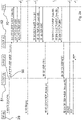
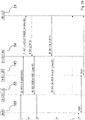
- FIG. 2a and 2b schematically depict a time-based flow diagram, which illustrates an exemplary flow of SIP-call setup messages used to establish the voice connection 120, 121 between the user device 20 and the user device 21, wherein the voice connection 120, 121 is routed through the network entity 100.
- SIP session description protocol
- SDP session description protocol
- user device 20 generates an invite message, which includes a request for establishment a voice connection between user A of user device 20 and user B of the user device 21.
- the invite message is transmitted to the P-CSCF 51 of the call session control system 50.
- an invite message is forwarded from P-CSCF 51 to S-CSCF 52.
- This message includes an information that user device 20 uses the A-BGF (A) 90 associated with core A of the call session control system 50.
- the invite message is forwarded to the telephony application server 70.
- the invite message is modified by the telephony application server 70 by adding an information indicating, that the first network entity 100 is to be switched into the requested voice connection 120, 121.
- TAS 70 may be configured to instruct now the first network entity 100 to be prepared to monitor the voice connection 120, 121 once it is established.
- the modified invite message is forwarded from the telephony application server 17 to the call session control system 50, in particular back to the S-SCFC 52.
- the invite message is then forwarded from the S-CSCF 52 to the S-CSCF 53 associated with the user B of the user device 21.
- the respective invite message is forwarded from the S-CSCF 53 to the P-CSCF 54 which is associated with the user device 22.
- the P-CSCF instance 54 forwards a invite message to the user device 21 indicating that user device 20 requests for a voice connection to user device 21.
- user device 21 In response to the invite message user device 21 generates a ringing message 180 and forwards it at step 8 to user device 20.
- the signaling message 183 is forwarded from user device 21 to the P-CSCF 54, which in turn forwards at step 10 a signaling message 183 to the S-CSCF 53.
- a signaling message 183 is forwarded from S-SCSCF 53 to the S-CSCF 52 associated with the user device 20.
- the signaling message 183 is forwarded from the S-CSCF 52 to the telephony application server 70.
- the telephony application server 70 forwards a signaling message 183 to the S-CSCF 52 indicating, that first network entity 100 is to be involved in the requested voice connection 120, 121.
- S-CSCF instance 52 forwards the signaling message 183 to the P-CSCF 51 informing this instance that network entity 100 is to be switched into the requested voice connection 120, 121.
- the signaling message 183 is forwarded to the user device 20.
- the user device 21 sends a signaling message 200 OK to its P-CSCF 54, which in turn forwards at step 17 a signaling message 200 OK to the S-CSCF 53.
- a signaling message 200 OK is send from S-CSCF 53 to the S-CSCF.
- the signaling message 200 OK is send to the telephony application server 17.
- the telephony application server 17 transmit a signaling message 200 OK to the S-CSCF 52 indicating that the network entity 100 will be switched into the requested voice connection.
- the S-CSCF 52 forwards the signaling message 200 OK to the P-CSCF 51.
- P-CSCF 51 sends a signaling message 200 OK to the user device 20.
- user device 20 sends an acknowledgment signaling message to the user device 21, which terminates the establishment of the voice connection 120, 121.
- voice connection 120, 121 between the user device 20 and the user device 21, wherein the voice connection 120, 121 is routed through the first network entity 100.
- voice data can be now transmitted via the established voice connection 120, 121 using for example the real-time transfer protocol.
- the telephony application server 70 may inform the network entity 100 on a predetermined keyword or a list of predetermined keywords to be used.
- the telephony application server 17 may be configured to instruct the network entity 100 to activate the monitoring function so that the network entity 100 is now prepared to monitor the voice connection 120, 121 to detect a predetermined keyword entered at the user device 20 or at the user device 21 and transmitted over the established voice connection 120, 121.
- the S-CSCF 52 may trigger the telephony application server 17 to instruct the network entity 100 to start, in particular, monitoring the voice connection 120, 121.
- the information to involve the telephony application server 70 can be retrieved by the S-CSCF 52 from the home subscriber server 60.
- the home subscriber server 60 can store a user profile for user A indicating that a voice assistance functionality should be activated once the user device 20 requests for a voice connection to a called party, for example to the user device 21 of user B.
- a user profile for user B can be stored on the HSS 60 or a separate HSS indicating that a voice assistance functionality should be activated once the user device 21 requests for a voice connection to a called party, for example to the user device 20 of user A.
- the user devices 20 and 21 are connected to each other via the voice connection 120, the voice assistance functionality is activated and the first network entity 100 is monitoring the voice connection 120, 121 and waiting for a predetermined keyword and voice data including voice commands.
- user A now enters a predetermined spoken keyword at its user device 20 and thereafter a voice information including a voice command.
- the user device 20 may be configured to convert the keyword into a digital keyword and the voice information into digital voice data, both of which are transmitted over voice connection 120, 121.
- the voice information including a voice command is entered by user A only, if an acknowledgment signal is received by the user device 20 from the first network entity 100 indicating that the keyword has been detected by the network entity 100. Therefore, the network entity 100 may be configured, to inform the user device 20 and user A, respectively, about the receipt and detection of the keyword.
- the network device 100 monitoring the voice connection, detects the entered predetermined keyword it records the received voice data entered as the voice information by the user A at the user device 20 and the recorded voice data is stored under control of the network entity 100 at the first storage location.
- the first storage location may be part of the database 130 or a file server, which the network entity 100 has access to.
- the network entity 100 is configured to inform the backend device 80 on the first storage location.
- the voice data stored at the first storage location in the database 130 is retrieved by the telephony application server 70, which in turn forwards the retrieved voice data to the backend device 80.
- the term "backend” is used to indicate, that voice data transmitted over the voice connection 120, 121 is preferably processed and converted into text at a remote physical server or device instead of a network entity which is switched into the voice connection 120, 121 or terminate the voice connection 120, 121, like the network entity 100 and the user devices 20, 21.
- the TAS 70 knows the addresses of the first network entity 100 and the backend device 80, the backend device knows the address of the TAS 70 and the first network entity 100 knows the address of the TAS 70.
- each address may include the IP-address or domain name and the port number of the respective network entity 70, 80 or 100 to allow communication between them.
- the user device 20 is preferably configured to convert the spoken keyword and the voice information into respective voice data and to transmit them in IP-packets over the established voice connection 120, 121 and thus through the first network entity 100.
- An IP-based transport protocol e.g. the real-time transport protocol (RTP) can be used to transmit voice data or voice streams over the established voice connection 120, 121.
- RTP real-time transport protocol
- the network entity 100 has been activated by the TAS 70 to monitor the voice connection 120 and 121 and to wait for a predetermined keyword, i.e. the predetermined keyword transmitted by the user device 20.
- the first network entity 100 informs the telephony application server 70 about this event.
- the TAS 70 instructs the first network entity 100 to record the voice data including a voice command following the detected keyword.
- the first network entity 100 stores the recorded voice data for example at a predetermined storage location on the storage system 130, which may comprise a database and/or a file server and informs the TAS 70 about this event and the storage location.
- the TAS 70 fetches the stored voice data from the database 130 and forward the voice data to the backend device 80.
- the voice information including a voice command may be entered by user A not directly after entering the predetermined keyword but only, if an acknowledgment signal is received by the user device 20 from the first network entity 100 indicating that the keyword has been detected by the network entity 100. Therefore, the network entity 100 may be configured, to inform the user device 20 and user A, respectively, about the receipt and detection of the keyword. Once the predetermined keyword is detected by the first network entity 100, the first network entity 100 informs the telephony application server 70 about this event.
- the TAS 70 may be configured to instruct in response to that information the network entity 100 to
- the TAS 70 fetches the stored voice data from the database 130 or the file server and forward the voice data to the backend device 80.
- the backend-device 80 is configured to process the voice data including the voice command entered by user A.
- the processing procedure may include the steps of recognizing the voice command included in the voice data and interpreting or semantically analyzing the voice command and optionally the step converting the voice command into a respective text to be used.
- Next backend-device 80 initiates a specific service function or a specific task in dependence of the recognized and semantically analyzed voice command.
- a voice command is considered which causes the backend device 80 to initiate a service function to provide audio data to be sent to the user devices 20 and 21.
- the backend-device 80 can be configured to provide the current time of day by itself or to query a respective application server configured to forward the current time of day to the backend-device 80.
- the backend-device 80 is configured to convert the current time of day into speech data and to transmit the speech data to the telephony application server 70.
- the TAS 70 may be configured to store the speech data representing the current time preferably at a predefined storage location on the database 130 or a file server and to instruct the first network entity 100 to retrieve the speech data from the database 130 and to transmit the speech data over the voice connection 120, 121 to the user devices 20 and 21. Finally the speech data can then be converted by the user devices 20 and 21 respectively and output acoustically.
- backend device 80 can be configured to initiate a specific service function or task in dependence of the respective voice command to provide the current name of the German chancellor.
- the backend device 80 may be configured to perform the service function which causes the backend device 80 to query a database or knowledge base (not shown) to obtain the name of the current German chancellor.
- the backend device 80 converts the name of the current German chancellor into speech data and transmits the speech data to the telephony application server 70.
- the TAS 70 may be configured to store the speech data representing the name of the current German chancellor preferably at a predefined storage location on the storage system 130, which may comprise a database and/or a file server and to instruct the first network entity 100 to retrieve the speech data from the storage system 130 and to transmit the speech data over the voice connection 120, 121 to the user devices 20 and 21. Finally the speech data can then be converted by the user devices 20 and 21 respectively and output acoustically.
- user A or user B may enter a voice command to request for a specific music song, which can be obtained by the backend device 80 and played out into the voice connection 120, 121 and transmitted to the user devices 20 and 21 as explained above. It should be noted, that the method of finding specific information in databases or in a distributed databases is well known to a persons skilled in the art.
- an exemplary voice command in the form of "Please setup a conference call to party C" can be entered by user A, which is forwarded to the backend device 80 as illustrated above.
- the backend-device 80 may be configured to process the voice data including this voice command to recognize and semantically analyze the voice command included therein and initiate a specific service function in dependence of the specific voice command, i.e. to initiate a service function to extend the existing voice connection 120, 121 to a conference call including party C.
- the TAS 70 may initiate a so called out-of-the-blue call (known technique) towards party C.
- the TAS 70 instructs the A-BGF of party C to send all the speech data from the user device of party C to the MRF network entity 100. Additionally, the TAS 70 instructs the network entity 100 to multiplex the voice data of the three users A. B and C in a way that all of them can hear and speak to each other.
- the TAS 70 Upon receiving replies from party C the TAS 70 is able to configure the network entity 100 where to send multiplexed voice data towards party C and its A-BGF, respectively, so that party C can be integrated into the existing call.
- A-BGF 90 and A-BGF 110 continue to send voice data to known destinations, e.g. the network entity 100 so that the conference call is possible in this way.
- known destinations e.g. the network entity 100 so that the conference call is possible in this way.
- This use case describes a particular example of the conference all, further similar scenarios with call forwarding, call barring etc. can be implemented in the same way with known existing IMS techniques.
- the backend device 80 may be configured to initiate the conference call service function in response to the recognized voice command by retrieving, e.g. from a respective server, the telephone number of the party C included in the voice command, send the telephone number to the TAS 70 and instructing it to extend the current voice connection 120, 121 to a conference call with party C.
- the TAS 70 can perform the respective steps in a known manner.
- the backend device 80 may involve one or more separate network entities, e.g. the TAS 70 and/or software modules and/or a database including a lookup table of names and its respective telephone numbers, to perform the conference call service function.
- the backend device 80 may be further configured to generate a voice answer once the conference call has been established.
- the voice answer e. g. "The conference call to party C has been successfully setup” can be converted by the backend device 80 into speech data and transmitted to the telephony application server 70.
- the TAS 70 may be configured to store the speech data representing the voice answer preferably at a predefined storage location on the storage system 130, which may comprise a database and/or a file server and to instruct the first network entity 100 to retrieve the speech data from the storage system 130 and to transmit the speech data over the voice connection 120, 121 to the user devices 20 and 21. Finally the speech data can then be converted by the user devices 20 and 21 respectively and output acoustically.
- the IP-based telecommunications system 10 may comprises a first network entity 100 configured to preferably detect a predefined keyword, a second network entity 80 configured to preferably process voice data including voice commands and plurality of user devices 20, 21, the method preferably comprising the following steps:
- a method for providing a voice assistance functionality to end users (A, B) by using a voice connection 120, 121 established over an IP-based telecommunications system 10 is provided.
- the IP-based telecommunications system 10 may comprises a first network entity 100 configured to preferably detect a predefined keyword, a second network entity 80 configured to preferably process voice data including voice commands and plurality of user devices 20, 21, the method preferably comprising the following steps:
- step f) may comprise the step of processing, by the second network entity 80, the voice data received at step e) to recognize and semantically analyze the voice command included therein.
- the method may further comprise a step g) for initiating and/or performing, by the second network entity 80, a service function or task in dependence of the voice command processed at step f).
- the service function may be a telephony-related service function.
- the step of initiating a service function in response to the voice command preferably means, that the second network entity 80 may involve one or more separate network entities, e.g. the telephony application server or other server devices and/or software modules, to perform this service function, e.g. querying a knowledge database or establishing a conference call to a third party.
- step a) may comprise the step of establishing the voice connection 120, 121 under control of a call session control system 50, wherein the signaling protocol is the Session Initiation Protocol (SIP).
- SIP Session Initiation Protocol
- step a) may further comprise the steps of:
- the method may comprise the steps of informing, by the third network entity 70, the first network entity 100 on the predetermined keyword to be used; and/or
- step d) may then comprise the steps of
- step g) may comprise the steps of
- the step of providing, at the second network entity, audio data in response to the voice command processed at step f) may further comprise the steps of:
- the step of transmitting the audio data to the first network entity 100 may comprise the steps of
- step g) may comprise the step of initiating, by the second network entity 80, a service function in response to the voice command recognized at step f) to setup of conference session between the first, the at least one second and at least a third use device 20, 21.
- the IP-based transport protocol may be for example a real-time transport protocol (RTP) and the call session control system 50 may be for example the IP Multimedia System (IMS).
- the call session control system may comprise a plurality of function, e.g. P-CSCF 51, 45 and S-CSCF 52, 53.
- the first network entity 100 may be configured to further perform at least one media resource function (MRF).
- MRF media resource function
- the third network entity 70 may be implemented as a telephony application server (TAS).
- TAS telephony application server
- the second network entity (80) may be a physical backend device or implemented as a virtual machine in a backend-device or system.
Landscapes
- Engineering & Computer Science (AREA)
- Multimedia (AREA)
- Computer Networks & Wireless Communication (AREA)
- Signal Processing (AREA)
- Business, Economics & Management (AREA)
- General Business, Economics & Management (AREA)
- Data Exchanges In Wide-Area Networks (AREA)
Priority Applications (1)
| Application Number | Priority Date | Filing Date | Title |
|---|---|---|---|
| EP21154776.5A EP4037349B1 (fr) | 2021-02-02 | 2021-02-02 | Procédé permettant de fournir une fonctionnalité d'aide vocale à l'utilisateur final au moyen d'une connexion vocale établie sur un système de télécommunications basé sur ip |
Applications Claiming Priority (1)
| Application Number | Priority Date | Filing Date | Title |
|---|---|---|---|
| EP21154776.5A EP4037349B1 (fr) | 2021-02-02 | 2021-02-02 | Procédé permettant de fournir une fonctionnalité d'aide vocale à l'utilisateur final au moyen d'une connexion vocale établie sur un système de télécommunications basé sur ip |
Publications (2)
| Publication Number | Publication Date |
|---|---|
| EP4037349A1 true EP4037349A1 (fr) | 2022-08-03 |
| EP4037349B1 EP4037349B1 (fr) | 2024-04-03 |
Family
ID=74505105
Family Applications (1)
| Application Number | Title | Priority Date | Filing Date |
|---|---|---|---|
| EP21154776.5A Active EP4037349B1 (fr) | 2021-02-02 | 2021-02-02 | Procédé permettant de fournir une fonctionnalité d'aide vocale à l'utilisateur final au moyen d'une connexion vocale établie sur un système de télécommunications basé sur ip |
Country Status (1)
| Country | Link |
|---|---|
| EP (1) | EP4037349B1 (fr) |
Cited By (1)
| Publication number | Priority date | Publication date | Assignee | Title |
|---|---|---|---|---|
| CN121393442A (zh) * | 2025-12-24 | 2026-01-23 | 天地阳光通信科技(北京)有限公司 | 一种基于智能语音识别的信令跨网穿透方法、系统及计算机可读存储介质 |
Citations (3)
| Publication number | Priority date | Publication date | Assignee | Title |
|---|---|---|---|---|
| WO2018068096A1 (fr) * | 2016-10-13 | 2018-04-19 | Optus Administration Pty Ltd | Procédé et système permettant d'offrir des services numériques lors d'un appel téléphonique |
| US10134395B2 (en) * | 2013-09-25 | 2018-11-20 | Amazon Technologies, Inc. | In-call virtual assistants |
| WO2020186499A1 (fr) * | 2019-03-21 | 2020-09-24 | Telefonaktiebolaget Lm Ericsson (Publ) | Nœuds de réseau et procédés mis en œuvre dans ceux-ci pour gérer des canaux multimédias pendant une session multimédia en cours |
-
2021
- 2021-02-02 EP EP21154776.5A patent/EP4037349B1/fr active Active
Patent Citations (3)
| Publication number | Priority date | Publication date | Assignee | Title |
|---|---|---|---|---|
| US10134395B2 (en) * | 2013-09-25 | 2018-11-20 | Amazon Technologies, Inc. | In-call virtual assistants |
| WO2018068096A1 (fr) * | 2016-10-13 | 2018-04-19 | Optus Administration Pty Ltd | Procédé et système permettant d'offrir des services numériques lors d'un appel téléphonique |
| WO2020186499A1 (fr) * | 2019-03-21 | 2020-09-24 | Telefonaktiebolaget Lm Ericsson (Publ) | Nœuds de réseau et procédés mis en œuvre dans ceux-ci pour gérer des canaux multimédias pendant une session multimédia en cours |
Non-Patent Citations (1)
| Title |
|---|
| "Technik der Netze", 2009, HIITHIG VERLAG |
Cited By (1)
| Publication number | Priority date | Publication date | Assignee | Title |
|---|---|---|---|---|
| CN121393442A (zh) * | 2025-12-24 | 2026-01-23 | 天地阳光通信科技(北京)有限公司 | 一种基于智能语音识别的信令跨网穿透方法、系统及计算机可读存储介质 |
Also Published As
| Publication number | Publication date |
|---|---|
| EP4037349B1 (fr) | 2024-04-03 |
Similar Documents
| Publication | Publication Date | Title |
|---|---|---|
| US12166663B2 (en) | System and method for client communication in a distributed telephony network | |
| EP1652359B1 (fr) | Procede et systeme permettant de supprimer les flux multimedia anticipes dans un reseau de communication | |
| RU2528616C1 (ru) | Шлюз сетевого обобщения и соответствующий способ обобщения оконечной точки | |
| US8451829B2 (en) | Routing a VoIP call with contextual information | |
| KR101130398B1 (ko) | 제3자 호 및 장치 제어를 용이하게 하기 위한 시스템 및방법 | |
| US8170194B2 (en) | Method and system for replicating ring back tones | |
| JP2002141955A (ja) | ローカライズされたVoIPを利用するための装置及び方法 | |
| US12477064B2 (en) | Call processing method, call processing apparatus, and related device | |
| US8913731B2 (en) | Method and system for providing an audio representation of a name | |
| EP1989866A2 (fr) | Telecommande de dispositif par telephone ou autres dispositifs de communication | |
| US7738638B1 (en) | Voice over internet protocol call recording | |
| US9854003B2 (en) | System and method for initiating telecommunications sessions through an electronic mail address | |
| WO2018068096A1 (fr) | Procédé et système permettant d'offrir des services numériques lors d'un appel téléphonique | |
| US8498222B2 (en) | VoIP-based invocation of PSTN-based AIN/IN services | |
| CN101448334B (zh) | 一种分布式业务的实现方法、装置及系统 | |
| US7747568B2 (en) | Integrated user interface | |
| EP4037349B1 (fr) | Procédé permettant de fournir une fonctionnalité d'aide vocale à l'utilisateur final au moyen d'une connexion vocale établie sur un système de télécommunications basé sur ip | |
| EP4231618A1 (fr) | Procédé de gestion et/ou de signalisation d'au moins un appel voip et système de communication | |
| EP1858218B1 (fr) | Procédé et entités permettant de fournir un enrichissement d'appel pour des appels vocaux, et combinaison sémantique de plusieurs sessions de service en une session de service combinée virtuellement. | |
| KR20020036009A (ko) | 통신망을 통해 음성을 송수신하는 방법 및 그 기록 매체 | |
| JP5677526B2 (ja) | 制御装置及び通信履歴管理方法 | |
| JP2014207709A (ja) | 端末 | |
| EP1713242A1 (fr) | Procédé pour l'établissement d'une communication |
Legal Events
| Date | Code | Title | Description |
|---|---|---|---|
| PUAI | Public reference made under article 153(3) epc to a published international application that has entered the european phase |
Free format text: ORIGINAL CODE: 0009012 |
|
| STAA | Information on the status of an ep patent application or granted ep patent |
Free format text: STATUS: THE APPLICATION HAS BEEN PUBLISHED |
|
| AK | Designated contracting states |
Kind code of ref document: A1 Designated state(s): AL AT BE BG CH CY CZ DE DK EE ES FI FR GB GR HR HU IE IS IT LI LT LU LV MC MK MT NL NO PL PT RO RS SE SI SK SM TR |
|
| STAA | Information on the status of an ep patent application or granted ep patent |
Free format text: STATUS: REQUEST FOR EXAMINATION WAS MADE |
|
| 17P | Request for examination filed |
Effective date: 20221103 |
|
| RBV | Designated contracting states (corrected) |
Designated state(s): AL AT BE BG CH CY CZ DE DK EE ES FI FR GB GR HR HU IE IS IT LI LT LU LV MC MK MT NL NO PL PT RO RS SE SI SK SM TR |
|
| GRAP | Despatch of communication of intention to grant a patent |
Free format text: ORIGINAL CODE: EPIDOSNIGR1 |
|
| STAA | Information on the status of an ep patent application or granted ep patent |
Free format text: STATUS: GRANT OF PATENT IS INTENDED |
|
| RIC1 | Information provided on ipc code assigned before grant |
Ipc: H04L 65/1089 20220101ALI20231011BHEP Ipc: H04L 65/1076 20220101ALI20231011BHEP Ipc: H04L 65/1016 20220101ALI20231011BHEP Ipc: H04W 4/16 20090101AFI20231011BHEP |
|
| INTG | Intention to grant announced |
Effective date: 20231030 |
|
| GRAS | Grant fee paid |
Free format text: ORIGINAL CODE: EPIDOSNIGR3 |
|
| GRAA | (expected) grant |
Free format text: ORIGINAL CODE: 0009210 |
|
| STAA | Information on the status of an ep patent application or granted ep patent |
Free format text: STATUS: THE PATENT HAS BEEN GRANTED |
|
| AK | Designated contracting states |
Kind code of ref document: B1 Designated state(s): AL AT BE BG CH CY CZ DE DK EE ES FI FR GB GR HR HU IE IS IT LI LT LU LV MC MK MT NL NO PL PT RO RS SE SI SK SM TR |
|
| REG | Reference to a national code |
Ref country code: CH Ref legal event code: EP |
|
| REG | Reference to a national code |
Ref country code: IE Ref legal event code: FG4D |
|
| REG | Reference to a national code |
Ref country code: DE Ref legal event code: R096 Ref document number: 602021011078 Country of ref document: DE |
|
| REG | Reference to a national code |
Ref country code: GR Ref legal event code: EP Ref document number: 20240401037 Country of ref document: GR Effective date: 20240611 |
|
| REG | Reference to a national code |
Ref country code: LT Ref legal event code: MG9D |
|
| REG | Reference to a national code |
Ref country code: NL Ref legal event code: MP Effective date: 20240403 |
|
| REG | Reference to a national code |
Ref country code: AT Ref legal event code: MK05 Ref document number: 1673719 Country of ref document: AT Kind code of ref document: T Effective date: 20240403 |
|
| PG25 | Lapsed in a contracting state [announced via postgrant information from national office to epo] |
Ref country code: NL Free format text: LAPSE BECAUSE OF FAILURE TO SUBMIT A TRANSLATION OF THE DESCRIPTION OR TO PAY THE FEE WITHIN THE PRESCRIBED TIME-LIMIT Effective date: 20240403 |
|
| PG25 | Lapsed in a contracting state [announced via postgrant information from national office to epo] |
Ref country code: NL Free format text: LAPSE BECAUSE OF FAILURE TO SUBMIT A TRANSLATION OF THE DESCRIPTION OR TO PAY THE FEE WITHIN THE PRESCRIBED TIME-LIMIT Effective date: 20240403 |
|
| PG25 | Lapsed in a contracting state [announced via postgrant information from national office to epo] |
Ref country code: IS Free format text: LAPSE BECAUSE OF FAILURE TO SUBMIT A TRANSLATION OF THE DESCRIPTION OR TO PAY THE FEE WITHIN THE PRESCRIBED TIME-LIMIT Effective date: 20240803 |
|
| PG25 | Lapsed in a contracting state [announced via postgrant information from national office to epo] |
Ref country code: BG Free format text: LAPSE BECAUSE OF FAILURE TO SUBMIT A TRANSLATION OF THE DESCRIPTION OR TO PAY THE FEE WITHIN THE PRESCRIBED TIME-LIMIT Effective date: 20240403 |
|
| PG25 | Lapsed in a contracting state [announced via postgrant information from national office to epo] |
Ref country code: HR Free format text: LAPSE BECAUSE OF FAILURE TO SUBMIT A TRANSLATION OF THE DESCRIPTION OR TO PAY THE FEE WITHIN THE PRESCRIBED TIME-LIMIT Effective date: 20240403 Ref country code: FI Free format text: LAPSE BECAUSE OF FAILURE TO SUBMIT A TRANSLATION OF THE DESCRIPTION OR TO PAY THE FEE WITHIN THE PRESCRIBED TIME-LIMIT Effective date: 20240403 |
|
| PG25 | Lapsed in a contracting state [announced via postgrant information from national office to epo] |
Ref country code: PT Free format text: LAPSE BECAUSE OF FAILURE TO SUBMIT A TRANSLATION OF THE DESCRIPTION OR TO PAY THE FEE WITHIN THE PRESCRIBED TIME-LIMIT Effective date: 20240805 |
|
| PG25 | Lapsed in a contracting state [announced via postgrant information from national office to epo] |
Ref country code: ES Free format text: LAPSE BECAUSE OF FAILURE TO SUBMIT A TRANSLATION OF THE DESCRIPTION OR TO PAY THE FEE WITHIN THE PRESCRIBED TIME-LIMIT Effective date: 20240403 |
|
| PG25 | Lapsed in a contracting state [announced via postgrant information from national office to epo] |
Ref country code: CZ Free format text: LAPSE BECAUSE OF FAILURE TO SUBMIT A TRANSLATION OF THE DESCRIPTION OR TO PAY THE FEE WITHIN THE PRESCRIBED TIME-LIMIT Effective date: 20240403 |
|
| PG25 | Lapsed in a contracting state [announced via postgrant information from national office to epo] |
Ref country code: AT Free format text: LAPSE BECAUSE OF FAILURE TO SUBMIT A TRANSLATION OF THE DESCRIPTION OR TO PAY THE FEE WITHIN THE PRESCRIBED TIME-LIMIT Effective date: 20240403 |
|
| PG25 | Lapsed in a contracting state [announced via postgrant information from national office to epo] |
Ref country code: PL Free format text: LAPSE BECAUSE OF FAILURE TO SUBMIT A TRANSLATION OF THE DESCRIPTION OR TO PAY THE FEE WITHIN THE PRESCRIBED TIME-LIMIT Effective date: 20240403 |
|
| PG25 | Lapsed in a contracting state [announced via postgrant information from national office to epo] |
Ref country code: LV Free format text: LAPSE BECAUSE OF FAILURE TO SUBMIT A TRANSLATION OF THE DESCRIPTION OR TO PAY THE FEE WITHIN THE PRESCRIBED TIME-LIMIT Effective date: 20240403 |
|
| PG25 | Lapsed in a contracting state [announced via postgrant information from national office to epo] |
Ref country code: PT Free format text: LAPSE BECAUSE OF FAILURE TO SUBMIT A TRANSLATION OF THE DESCRIPTION OR TO PAY THE FEE WITHIN THE PRESCRIBED TIME-LIMIT Effective date: 20240805 Ref country code: PL Free format text: LAPSE BECAUSE OF FAILURE TO SUBMIT A TRANSLATION OF THE DESCRIPTION OR TO PAY THE FEE WITHIN THE PRESCRIBED TIME-LIMIT Effective date: 20240403 Ref country code: NO Free format text: LAPSE BECAUSE OF FAILURE TO SUBMIT A TRANSLATION OF THE DESCRIPTION OR TO PAY THE FEE WITHIN THE PRESCRIBED TIME-LIMIT Effective date: 20240703 Ref country code: LV Free format text: LAPSE BECAUSE OF FAILURE TO SUBMIT A TRANSLATION OF THE DESCRIPTION OR TO PAY THE FEE WITHIN THE PRESCRIBED TIME-LIMIT Effective date: 20240403 Ref country code: IS Free format text: LAPSE BECAUSE OF FAILURE TO SUBMIT A TRANSLATION OF THE DESCRIPTION OR TO PAY THE FEE WITHIN THE PRESCRIBED TIME-LIMIT Effective date: 20240803 Ref country code: HR Free format text: LAPSE BECAUSE OF FAILURE TO SUBMIT A TRANSLATION OF THE DESCRIPTION OR TO PAY THE FEE WITHIN THE PRESCRIBED TIME-LIMIT Effective date: 20240403 Ref country code: FI Free format text: LAPSE BECAUSE OF FAILURE TO SUBMIT A TRANSLATION OF THE DESCRIPTION OR TO PAY THE FEE WITHIN THE PRESCRIBED TIME-LIMIT Effective date: 20240403 Ref country code: ES Free format text: LAPSE BECAUSE OF FAILURE TO SUBMIT A TRANSLATION OF THE DESCRIPTION OR TO PAY THE FEE WITHIN THE PRESCRIBED TIME-LIMIT Effective date: 20240403 Ref country code: CZ Free format text: LAPSE BECAUSE OF FAILURE TO SUBMIT A TRANSLATION OF THE DESCRIPTION OR TO PAY THE FEE WITHIN THE PRESCRIBED TIME-LIMIT Effective date: 20240403 Ref country code: BG Free format text: LAPSE BECAUSE OF FAILURE TO SUBMIT A TRANSLATION OF THE DESCRIPTION OR TO PAY THE FEE WITHIN THE PRESCRIBED TIME-LIMIT Effective date: 20240403 Ref country code: AT Free format text: LAPSE BECAUSE OF FAILURE TO SUBMIT A TRANSLATION OF THE DESCRIPTION OR TO PAY THE FEE WITHIN THE PRESCRIBED TIME-LIMIT Effective date: 20240403 Ref country code: RS Free format text: LAPSE BECAUSE OF FAILURE TO SUBMIT A TRANSLATION OF THE DESCRIPTION OR TO PAY THE FEE WITHIN THE PRESCRIBED TIME-LIMIT Effective date: 20240703 |
|
| REG | Reference to a national code |
Ref country code: DE Ref legal event code: R097 Ref document number: 602021011078 Country of ref document: DE |
|
| PG25 | Lapsed in a contracting state [announced via postgrant information from national office to epo] |
Ref country code: DK Free format text: LAPSE BECAUSE OF FAILURE TO SUBMIT A TRANSLATION OF THE DESCRIPTION OR TO PAY THE FEE WITHIN THE PRESCRIBED TIME-LIMIT Effective date: 20240403 |
|
| PG25 | Lapsed in a contracting state [announced via postgrant information from national office to epo] |
Ref country code: EE Free format text: LAPSE BECAUSE OF FAILURE TO SUBMIT A TRANSLATION OF THE DESCRIPTION OR TO PAY THE FEE WITHIN THE PRESCRIBED TIME-LIMIT Effective date: 20240403 |
|
| PG25 | Lapsed in a contracting state [announced via postgrant information from national office to epo] |
Ref country code: SK Free format text: LAPSE BECAUSE OF FAILURE TO SUBMIT A TRANSLATION OF THE DESCRIPTION OR TO PAY THE FEE WITHIN THE PRESCRIBED TIME-LIMIT Effective date: 20240403 Ref country code: RO Free format text: LAPSE BECAUSE OF FAILURE TO SUBMIT A TRANSLATION OF THE DESCRIPTION OR TO PAY THE FEE WITHIN THE PRESCRIBED TIME-LIMIT Effective date: 20240403 |
|
| PG25 | Lapsed in a contracting state [announced via postgrant information from national office to epo] |
Ref country code: SM Free format text: LAPSE BECAUSE OF FAILURE TO SUBMIT A TRANSLATION OF THE DESCRIPTION OR TO PAY THE FEE WITHIN THE PRESCRIBED TIME-LIMIT Effective date: 20240403 |
|
| PG25 | Lapsed in a contracting state [announced via postgrant information from national office to epo] |
Ref country code: SM Free format text: LAPSE BECAUSE OF FAILURE TO SUBMIT A TRANSLATION OF THE DESCRIPTION OR TO PAY THE FEE WITHIN THE PRESCRIBED TIME-LIMIT Effective date: 20240403 Ref country code: SK Free format text: LAPSE BECAUSE OF FAILURE TO SUBMIT A TRANSLATION OF THE DESCRIPTION OR TO PAY THE FEE WITHIN THE PRESCRIBED TIME-LIMIT Effective date: 20240403 Ref country code: RO Free format text: LAPSE BECAUSE OF FAILURE TO SUBMIT A TRANSLATION OF THE DESCRIPTION OR TO PAY THE FEE WITHIN THE PRESCRIBED TIME-LIMIT Effective date: 20240403 Ref country code: EE Free format text: LAPSE BECAUSE OF FAILURE TO SUBMIT A TRANSLATION OF THE DESCRIPTION OR TO PAY THE FEE WITHIN THE PRESCRIBED TIME-LIMIT Effective date: 20240403 Ref country code: DK Free format text: LAPSE BECAUSE OF FAILURE TO SUBMIT A TRANSLATION OF THE DESCRIPTION OR TO PAY THE FEE WITHIN THE PRESCRIBED TIME-LIMIT Effective date: 20240403 |
|
| PLBE | No opposition filed within time limit |
Free format text: ORIGINAL CODE: 0009261 |
|
| STAA | Information on the status of an ep patent application or granted ep patent |
Free format text: STATUS: NO OPPOSITION FILED WITHIN TIME LIMIT |
|
| 26N | No opposition filed |
Effective date: 20250106 |
|
| PG25 | Lapsed in a contracting state [announced via postgrant information from national office to epo] |
Ref country code: SI Free format text: LAPSE BECAUSE OF FAILURE TO SUBMIT A TRANSLATION OF THE DESCRIPTION OR TO PAY THE FEE WITHIN THE PRESCRIBED TIME-LIMIT Effective date: 20240403 |
|
| PG25 | Lapsed in a contracting state [announced via postgrant information from national office to epo] |
Ref country code: SE Free format text: LAPSE BECAUSE OF FAILURE TO SUBMIT A TRANSLATION OF THE DESCRIPTION OR TO PAY THE FEE WITHIN THE PRESCRIBED TIME-LIMIT Effective date: 20240403 |
|
| PG25 | Lapsed in a contracting state [announced via postgrant information from national office to epo] |
Ref country code: MC Free format text: LAPSE BECAUSE OF FAILURE TO SUBMIT A TRANSLATION OF THE DESCRIPTION OR TO PAY THE FEE WITHIN THE PRESCRIBED TIME-LIMIT Effective date: 20240403 |
|
| REG | Reference to a national code |
Ref country code: CH Ref legal event code: PL |
|
| PG25 | Lapsed in a contracting state [announced via postgrant information from national office to epo] |
Ref country code: GR Free format text: LAPSE BECAUSE OF NON-PAYMENT OF DUE FEES Effective date: 20250903 |
|
| PG25 | Lapsed in a contracting state [announced via postgrant information from national office to epo] |
Ref country code: LU Free format text: LAPSE BECAUSE OF NON-PAYMENT OF DUE FEES Effective date: 20250202 |
|
| PG25 | Lapsed in a contracting state [announced via postgrant information from national office to epo] |
Ref country code: CH Free format text: LAPSE BECAUSE OF NON-PAYMENT OF DUE FEES Effective date: 20250228 |
|
| REG | Reference to a national code |
Ref country code: BE Ref legal event code: MM Effective date: 20250228 |
|
| PG25 | Lapsed in a contracting state [announced via postgrant information from national office to epo] |
Ref country code: BE Free format text: LAPSE BECAUSE OF NON-PAYMENT OF DUE FEES Effective date: 20250228 |
|
| PG25 | Lapsed in a contracting state [announced via postgrant information from national office to epo] |
Ref country code: IE Free format text: LAPSE BECAUSE OF NON-PAYMENT OF DUE FEES Effective date: 20250202 |
|
| PG25 | Lapsed in a contracting state [announced via postgrant information from national office to epo] |
Ref country code: IT Free format text: LAPSE BECAUSE OF FAILURE TO SUBMIT A TRANSLATION OF THE DESCRIPTION OR TO PAY THE FEE WITHIN THE PRESCRIBED TIME-LIMIT Effective date: 20240403 |
|
| PGFP | Annual fee paid to national office [announced via postgrant information from national office to epo] |
Ref country code: GB Payment date: 20260219 Year of fee payment: 6 |
|
| PGFP | Annual fee paid to national office [announced via postgrant information from national office to epo] |
Ref country code: DE Payment date: 20260217 Year of fee payment: 6 |
|
| PGFP | Annual fee paid to national office [announced via postgrant information from national office to epo] |
Ref country code: FR Payment date: 20260223 Year of fee payment: 6 |