EP4038251B1 - Ensemble verrou électromécanique à élément annulaire, dispositifs de blocage et de retenue - Google Patents
Ensemble verrou électromécanique à élément annulaire, dispositifs de blocage et de retenue Download PDFInfo
- Publication number
- EP4038251B1 EP4038251B1 EP20871274.5A EP20871274A EP4038251B1 EP 4038251 B1 EP4038251 B1 EP 4038251B1 EP 20871274 A EP20871274 A EP 20871274A EP 4038251 B1 EP4038251 B1 EP 4038251B1
- Authority
- EP
- European Patent Office
- Prior art keywords
- lock
- annular element
- lock core
- key
- electromechanical
- Prior art date
- Legal status (The legal status is an assumption and is not a legal conclusion. Google has not performed a legal analysis and makes no representation as to the accuracy of the status listed.)
- Active
Links
Images



Classifications
-
- E—FIXED CONSTRUCTIONS
- E05—LOCKS; KEYS; WINDOW OR DOOR FITTINGS; SAFES
- E05B—LOCKS; ACCESSORIES THEREFOR; HANDCUFFS
- E05B47/00—Operating or controlling locks or other fastening devices by electric or magnetic means
- E05B47/06—Controlling mechanically-operated bolts by electro-magnetically-operated detents
- E05B47/0611—Cylinder locks with electromagnetic control
- E05B47/0638—Cylinder locks with electromagnetic control by disconnecting the rotor
- E05B47/0646—Cylinder locks with electromagnetic control by disconnecting the rotor radially
- E05B47/0653—Cylinder locks with electromagnetic control by disconnecting the rotor radially with a pivotally moveable coupling element
-
- G—PHYSICS
- G07—CHECKING-DEVICES
- G07C—TIME OR ATTENDANCE REGISTERS; REGISTERING OR INDICATING THE WORKING OF MACHINES; GENERATING RANDOM NUMBERS; VOTING OR LOTTERY APPARATUS; ARRANGEMENTS, SYSTEMS OR APPARATUS FOR CHECKING NOT PROVIDED FOR ELSEWHERE
- G07C9/00—Individual registration on entry or exit
- G07C9/00174—Electronically operated locks; Circuits therefor; Nonmechanical keys therefor, e.g. passive or active electrical keys or other data carriers without mechanical keys
- G07C9/00944—Details of construction or manufacture
-
- E—FIXED CONSTRUCTIONS
- E05—LOCKS; KEYS; WINDOW OR DOOR FITTINGS; SAFES
- E05B—LOCKS; ACCESSORIES THEREFOR; HANDCUFFS
- E05B27/00—Cylinder locks or other locks with tumbler pins or balls that are set by pushing the key in
- E05B27/0042—Cylinder locks or other locks with tumbler pins or balls that are set by pushing the key in with additional key identifying function, e.g. with use of additional key operated rotor-blocking elements, not of split pin tumbler type
-
- E—FIXED CONSTRUCTIONS
- E05—LOCKS; KEYS; WINDOW OR DOOR FITTINGS; SAFES
- E05B—LOCKS; ACCESSORIES THEREFOR; HANDCUFFS
- E05B35/00—Locks for use with special keys or a plurality of keys ; keys therefor
- E05B35/001—Locks for use with special keys or a plurality of keys ; keys therefor with key identifying function
-
- E—FIXED CONSTRUCTIONS
- E05—LOCKS; KEYS; WINDOW OR DOOR FITTINGS; SAFES
- E05B—LOCKS; ACCESSORIES THEREFOR; HANDCUFFS
- E05B47/00—Operating or controlling locks or other fastening devices by electric or magnetic means
- E05B47/0001—Operating or controlling locks or other fastening devices by electric or magnetic means with electric actuators; Constructional features thereof
- E05B47/0002—Operating or controlling locks or other fastening devices by electric or magnetic means with electric actuators; Constructional features thereof with electromagnets
- E05B47/0006—Operating or controlling locks or other fastening devices by electric or magnetic means with electric actuators; Constructional features thereof with electromagnets having a non-movable core; with permanent magnet
-
- E—FIXED CONSTRUCTIONS
- E05—LOCKS; KEYS; WINDOW OR DOOR FITTINGS; SAFES
- E05B—LOCKS; ACCESSORIES THEREFOR; HANDCUFFS
- E05B47/00—Operating or controlling locks or other fastening devices by electric or magnetic means
- E05B47/06—Controlling mechanically-operated bolts by electro-magnetically-operated detents
- E05B47/0611—Cylinder locks with electromagnetic control
- E05B47/0638—Cylinder locks with electromagnetic control by disconnecting the rotor
- E05B47/0642—Cylinder locks with electromagnetic control by disconnecting the rotor axially, i.e. with an axially disengaging coupling element
-
- E—FIXED CONSTRUCTIONS
- E05—LOCKS; KEYS; WINDOW OR DOOR FITTINGS; SAFES
- E05B—LOCKS; ACCESSORIES THEREFOR; HANDCUFFS
- E05B47/00—Operating or controlling locks or other fastening devices by electric or magnetic means
- E05B47/06—Controlling mechanically-operated bolts by electro-magnetically-operated detents
- E05B47/0676—Controlling mechanically-operated bolts by electro-magnetically-operated detents by disconnecting the handle
- E05B47/068—Controlling mechanically-operated bolts by electro-magnetically-operated detents by disconnecting the handle axially, i.e. with an axially disengaging coupling element
-
- E—FIXED CONSTRUCTIONS
- E05—LOCKS; KEYS; WINDOW OR DOOR FITTINGS; SAFES
- E05B—LOCKS; ACCESSORIES THEREFOR; HANDCUFFS
- E05B47/00—Operating or controlling locks or other fastening devices by electric or magnetic means
- E05B47/06—Controlling mechanically-operated bolts by electro-magnetically-operated detents
- E05B47/0676—Controlling mechanically-operated bolts by electro-magnetically-operated detents by disconnecting the handle
- E05B47/0684—Controlling mechanically-operated bolts by electro-magnetically-operated detents by disconnecting the handle radially
- E05B47/0692—Controlling mechanically-operated bolts by electro-magnetically-operated detents by disconnecting the handle radially with a rectilinearly moveable coupling element
-
- G—PHYSICS
- G07—CHECKING-DEVICES
- G07C—TIME OR ATTENDANCE REGISTERS; REGISTERING OR INDICATING THE WORKING OF MACHINES; GENERATING RANDOM NUMBERS; VOTING OR LOTTERY APPARATUS; ARRANGEMENTS, SYSTEMS OR APPARATUS FOR CHECKING NOT PROVIDED FOR ELSEWHERE
- G07C9/00—Individual registration on entry or exit
- G07C9/00174—Electronically operated locks; Circuits therefor; Nonmechanical keys therefor, e.g. passive or active electrical keys or other data carriers without mechanical keys
-
- G—PHYSICS
- G07—CHECKING-DEVICES
- G07C—TIME OR ATTENDANCE REGISTERS; REGISTERING OR INDICATING THE WORKING OF MACHINES; GENERATING RANDOM NUMBERS; VOTING OR LOTTERY APPARATUS; ARRANGEMENTS, SYSTEMS OR APPARATUS FOR CHECKING NOT PROVIDED FOR ELSEWHERE
- G07C9/00—Individual registration on entry or exit
- G07C9/00174—Electronically operated locks; Circuits therefor; Nonmechanical keys therefor, e.g. passive or active electrical keys or other data carriers without mechanical keys
- G07C9/00182—Electronically operated locks; Circuits therefor; Nonmechanical keys therefor, e.g. passive or active electrical keys or other data carriers without mechanical keys operated with unidirectional data transmission between data carrier and locks
-
- E—FIXED CONSTRUCTIONS
- E05—LOCKS; KEYS; WINDOW OR DOOR FITTINGS; SAFES
- E05B—LOCKS; ACCESSORIES THEREFOR; HANDCUFFS
- E05B47/00—Operating or controlling locks or other fastening devices by electric or magnetic means
- E05B2047/0048—Circuits, feeding, monitoring
- E05B2047/0057—Feeding
- E05B2047/0063—Energy transfer from key to lock, e.g. for emergency opening
-
- E—FIXED CONSTRUCTIONS
- E05—LOCKS; KEYS; WINDOW OR DOOR FITTINGS; SAFES
- E05B—LOCKS; ACCESSORIES THEREFOR; HANDCUFFS
- E05B47/00—Operating or controlling locks or other fastening devices by electric or magnetic means
- E05B2047/0084—Key or electric means; Emergency release
- E05B2047/0085—Key and electromagnet
-
- G—PHYSICS
- G07—CHECKING-DEVICES
- G07C—TIME OR ATTENDANCE REGISTERS; REGISTERING OR INDICATING THE WORKING OF MACHINES; GENERATING RANDOM NUMBERS; VOTING OR LOTTERY APPARATUS; ARRANGEMENTS, SYSTEMS OR APPARATUS FOR CHECKING NOT PROVIDED FOR ELSEWHERE
- G07C9/00—Individual registration on entry or exit
- G07C9/00174—Electronically operated locks; Circuits therefor; Nonmechanical keys therefor, e.g. passive or active electrical keys or other data carriers without mechanical keys
- G07C2009/00634—Power supply for the lock
-
- G—PHYSICS
- G07—CHECKING-DEVICES
- G07C—TIME OR ATTENDANCE REGISTERS; REGISTERING OR INDICATING THE WORKING OF MACHINES; GENERATING RANDOM NUMBERS; VOTING OR LOTTERY APPARATUS; ARRANGEMENTS, SYSTEMS OR APPARATUS FOR CHECKING NOT PROVIDED FOR ELSEWHERE
- G07C9/00—Individual registration on entry or exit
- G07C9/00174—Electronically operated locks; Circuits therefor; Nonmechanical keys therefor, e.g. passive or active electrical keys or other data carriers without mechanical keys
- G07C2009/00753—Electronically operated locks; Circuits therefor; Nonmechanical keys therefor, e.g. passive or active electrical keys or other data carriers without mechanical keys operated by active electrical keys
- G07C2009/00761—Electronically operated locks; Circuits therefor; Nonmechanical keys therefor, e.g. passive or active electrical keys or other data carriers without mechanical keys operated by active electrical keys with data transmission performed by connected means, e.g. mechanical contacts, plugs, connectors
-
- G—PHYSICS
- G07—CHECKING-DEVICES
- G07C—TIME OR ATTENDANCE REGISTERS; REGISTERING OR INDICATING THE WORKING OF MACHINES; GENERATING RANDOM NUMBERS; VOTING OR LOTTERY APPARATUS; ARRANGEMENTS, SYSTEMS OR APPARATUS FOR CHECKING NOT PROVIDED FOR ELSEWHERE
- G07C9/00—Individual registration on entry or exit
- G07C9/00174—Electronically operated locks; Circuits therefor; Nonmechanical keys therefor, e.g. passive or active electrical keys or other data carriers without mechanical keys
- G07C9/00857—Electronically operated locks; Circuits therefor; Nonmechanical keys therefor, e.g. passive or active electrical keys or other data carriers without mechanical keys where the code of the data carrier can be programmed
- G07C2009/00865—Electronically operated locks; Circuits therefor; Nonmechanical keys therefor, e.g. passive or active electrical keys or other data carriers without mechanical keys where the code of the data carrier can be programmed remotely by wireless communication
-
- G—PHYSICS
- G07—CHECKING-DEVICES
- G07C—TIME OR ATTENDANCE REGISTERS; REGISTERING OR INDICATING THE WORKING OF MACHINES; GENERATING RANDOM NUMBERS; VOTING OR LOTTERY APPARATUS; ARRANGEMENTS, SYSTEMS OR APPARATUS FOR CHECKING NOT PROVIDED FOR ELSEWHERE
- G07C9/00—Individual registration on entry or exit
- G07C9/00174—Electronically operated locks; Circuits therefor; Nonmechanical keys therefor, e.g. passive or active electrical keys or other data carriers without mechanical keys
- G07C9/00857—Electronically operated locks; Circuits therefor; Nonmechanical keys therefor, e.g. passive or active electrical keys or other data carriers without mechanical keys where the code of the data carrier can be programmed
Definitions
- the present invention relates to an electromechanical lock assembly, which is configured to be powered by insertion of a programmable key in a key receptacle, said lock assembly comprising a lock body, a lock core located at least partially within the lock body and selectively rotatable with respect to the lock body, the lock core including a key receptacle for receiving a programmable key, a lock bolt operating member rotationally secured to the lock core and configured to move a lock bolt of a lock for locking and unlocking said lock, and an electronic access control device.
- EP 1 960 622 B2 shows an electromechanical locking system that comprises a lock core, a tailpiece and an electrically-operated clutch mechanism for rotatably coupling the tailpiece to the lock core.
- the lock core includes a keyway for a key having an electrical power source and electrical connection means which provides an electrical connection with the electrical power source of the key.
- An object of the present invention is to at least partly overcome the above-mentioned drawbacks and to provide an improved electromechanical lock assembly.
- an electromechanical lock assembly which is configured to be powered upon insertion of a programmable key in a key receptacle
- said lock assembly comprising a lock body, a lock core located at least partially within the lock body and selectively rotatable with respect to the lock body, the lock core including a key receptacle for receiving a programmable key, a lock bolt operating member rotationally secured to the lock core and configured to move a lock bolt of a lock for locking and unlocking said lock, and an electronic access control device
- the lock assembly further comprises an annular element which is rotatably and axially displaceably mounted on said lock core, a coupling device arranged to communicate with said electronic access control device and, upon the insertion of an appropriate key in the key receptacle, rotationally lock the annular element to the lock core, thereby enabling rotation of the lock core and thereby enabling locking and unlocking of said lock with said appropriate key
- the coupling device Upon the insertion of an appropriate key, the coupling device thus couples the annular element to the lock core, which prevents the lock core from rotating together relative to the annular element and thereby enables locking and unlocking rotation of the lock core.
- the coupling device thus serves to enable locking and unlocking rotation of the lock core and the lock operating member which is arranged to rotate together with the lock core.
- the annular element is maintained in a non-blocking position as long as an appropriate key is inserted in the key receptacle.
- the lock core is formed as an integral part and the lock bolt operating member is never disengaged from the lock core. In this solution there is thus no need to rotationally couple separate parts of a lock core. This enables a simple solution having few parts and that is easy to manufacture and assemble. Also, it provides for a solution that can be used together with different types of lock sets in an easy manner. Furthermore, this solution allows the use of an electrical actuator to be minimized, which provides for a very power efficient solution.
- the annular element If the lock core is rotated using an inapproriate key, the annular element is moved into a blocking position, in which it engages each of the lock core and the stationary blocking member. Then, the annular element, blocks further rotation of the lock core. In this manner, the blocking arrangement blocks unauthorized locking and unlocking rotation of the lock core, and consequently unauthorized locking and unlocking of an associated lock, in a robust and reliable manner.
- the blocking arrangement thus provides for a very robust and reliable solution.
- the electromechanical lock assembly may require the need of an electrical actuator under only a very short period of time. This has the advantage that the assembly requires very little power to operate.
- the coupling device comprises an electric actuator arranged to move a coupling member from a rest position, in which it allows the lock core to rotate relative to the annular element, to a coupling position in which it rotationally locks said annular element to said lock core.
- the coupling device may thus comprise an electric actuator, such as e.g. a solenoid, having a coupling member being movable between a rest position, in which the movable member is situated when the electric actuator is powerless, and a coupling position, in which the coupling member is situated when the electric actuator is powered and in which it rotationally locks the annular element to the lock core.
- an electric actuator such as e.g. a solenoid
- a coupling member being movable between a rest position, in which the movable member is situated when the electric actuator is powerless, and a coupling position, in which the coupling member is situated when the electric actuator is powered and in which it rotationally locks the annular element to the lock core.
- the annular element is movable between a non-blocking position, to which it is biased by a biasing member, and a blocking position.
- the coupling member is pivotable or rotatable between said rest position and said coupling position.
- a coupling member in the form of a pivotable arm or a rotatable disc may thus be used.
- the coupling member is linearly displaceable between said rest position and said coupling position.
- a coupling member in the form of a linearly displaceable rod may thus be used.
- the electric actuator is a solenoid, which has the advantage that an assembly with very low power consumption may be achieved.
- said retainer device comprises a retaining member which is received in a recess formed in the annular element, which provides for a very robust and reliable solution.
- said retaining member is a ball and preferably a spring biased ball.
- said recess is an axial groove.
- the lock assembly further comprises an axial movement limiting device arranged to limit axial movement of the annular element relative to the lock core.
- the axial movement limiting device thus maintains the annular element rotationally coupled to the lock core. This allows for an assembly with even less power consumption, since the electrical actuator need to be powered only in the initial phase of the rotation of the lock core, i.e. under a very short period of time when rotation of the lock core relative to the annular element is initiated.
- the axial movement limiting device is thus arranged to maintain the annular element in a non-blocking position.
- the axial movement limiting device comprises at least one ball received in a radial groove formed in the annular element, which provides for a very robust and reliable solution.
- the lock body is cylindrical.
- Fig. 1 illustrates an electromechanical lock assembly, in the form of an electromechanical lock cylinder 1, according to a first embodiment of the invention that forms part of an electromechanical lock 3 arranged at a door 5.
- the electromechanical lock cylinder 1 is connected to an existing locking mechanism 7 of the electromechanical lock 3.
- the door 5 may be a front door to a building such as a house or to an apartment.
- the electromechanical lock cylinder 1 is arranged in connection with a first bore 9 on the exterior side of the door 5 and an interior locking device (not shown), like a knob, on the interior side of the door 5.
- a lock housing 11 holding the locking mechanism 7 is arranged in a cavity of the door 5.
- the locking mechanism 7 and the lock housing 11 are of common sort, which are well known in the art, and not described in detail here.
- the locking mechanism 7 may be of any kind known in the art which is arranged in a lock housing in a cavity of a door 5.
- the locking mechanism 3 cooperates, via a lock bolt 13 with a striking plate (not shown) arranged in a door frame (not shown) to lock the door 5.
- the locking mechanism 7 controls the lock bolt 13 via the electromechanical lock cylinder 1 from the exterior side of the door 5 and via the interior locking device from the interior side of the door 5 in a well known manner.
- the locking mechanism 7 is coupled to the lock bolt 13 by a conventional coupling means (not shown) so as to actuate the lock bolt 13.
- the electromechanical lock cylinder 1 comprises a lock body, in the form of a cylinder body 15, a lock core 17 located within the cylinder body 15 and a lock bolt operating member 19.
- the lock core 17 is selectively rotatable with respect to the cylinder body 15.
- a fixing device is arranged to prevent the lock core 17 from being retracted from the cylinder body 13.
- This fixing device may comprise balls (not shown) partly received in a radial groove (not shown) formed in the cylinder body 13 and partly received in a radial groove 18 formed in the lock core 17.
- the lock bolt operating member 19 is rotationally secured to the lock core 13. To this end the lock operating member 19 is provided with a recess 21 configured to receive a projecting portion (not shown) of the lock core 17.
- the lock bolt operating member 19 is thus arranged to rotate together with the lock core 17.
- the lock bolt operating member 19 is configured to operate the lock bolt 13 of the locking mechanism 7 for locking and unlocking the lock 3.
- the lock bolt operating member 19 has a projecting portion 22 which is arranged to be received in a recess 23 of the locking mechanism 7.
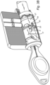
- the electromechanical lock cylinder 1 comprises the cylinder body 15, the lock core 17, a coupling device 25, an annular element 27, a retainer device 29, an axial movement limiting device 31, a biasing member in the form of a spring 33, and a stationary blocking member 35.
- the lock core 17, which is formed as an integral part, comprises a key receptacle 37 for receiving a programmable key.
- a programmable key which is used to operate an electromechanical lock, comprises an energy source, such as a battery, and a control unit powered by the energy source.
- the key can access a cloud based or locally hosted access control system which transfer authorization data to the key or log information from the key via internet and a synchronization unit or via a mobile communication system such as the GSM net and a mobile device, such as a mobile phone.
- the mobile device is the key itself.
- the key is accessed from the synchronization unit or the mobile device by a physical contact, by near field communication, such as NFC, or by radio communication, such as Bluetooth.
- the key can store all data necessary to access at least one specific electromechanical key lock, but cannot access any electromechanical locks for which it does not have the appropriate authorization data.
- the electromechanical lock cylinder 1 is configured to be powered by and communicate with such a programmable key upon the insertion of the key in the key receptacle 37. To this end the electromechanical lock cylinder 1 comprises power receiving means, communication means and an electrical control unit. The electromechanical lock cylinder 1 further comprises an access control device 20 for controlling access of a key inserted in the key receptacle 37. Also, the key receptacle 37 of the lock core 17 is configured such that the lock core 17 rotates together with a programmable key.
- the annular element 27 is rotatably and axially displaceably mounted on the hollow lock core portion 39.
- the coupling device 25 is accommodated inside the hollow lock core portion 39 and secured thereto so as to rotate together therewith.
- the coupling device 25 is arranged to, upon the insertion of an appropriate key in the key receptacle 37, rotationally couple the annular element 27 to the lock core 17.
- the coupling device 25 comprises an electric actuator 41 which is configured to communicate with the access control device.
- the electric actuator 41 has a pivotable arm 43, as illustrated by arrow A in Fig. 2 .
- the pivotable arm 43 is movable between a rest position, in which rotation of the annular element 27 relative to the lock core 17 is allowed, and a coupling position in which the annular element 27 is rotationally coupled to the lock core 17 by the coupling arm 43.
- the annular element 27 has a coupling recess 44 which is configured to receive the coupling arm 43 of the coupling device 25.
- the coupling device 25 is thus arranged to, upon the insertion of an appropriate key in the key receptacle 37, rotationally lock the annular element 27 to the lock core 17, which enables locking and unlocking rotation of the lock core 17 and thereby enables locking and unlocking of the lock 3, as will be described in detail later with reference to Figs. 3A-C .
- a first end of the annular element 27 forms an engagement portion 27a which is configured to mate an engagement portion 17a of the lock core 17.
- the engagement portion 17a of the lock core 17 comprises a first contact surface forming a first ramp surface 45 and the engagement portion 27a of the annular element 27 comprises a second contact surface forming a second ramp surface 47.
- the first and second ramp surfaces 45, 47 together form a sliding interface capable of, upon rotation of the lock core 17 relative to the annular element 27, axially displacing the annular element 27 in a direction toward the stationary blocking member 35 into engagement with an engagement portion thereof. Upon such engagement further rotation of the lock core 17 is prevented.
- a second end of the annular element 27 is provided with a blocking portion 27b configured to engage the engagement portion 49 of the stationary blocking member 35.
- the annular element 27 is thus movable between a non-blocking position, to which it is biased by the spring 33, and a blocking position.
- the annular element 27 is biased against the lock core 17 by the spring 33 to secure that the ramp surfaces 45, 47 of the sliding interface always are in contact with each other.
- the first retainer device 29 is arranged to prevent the annular element 27 from rotating together with the lock core 17 when it is rotated with an inappropriate key, i.e. when the coupling arm 43 is situated in the rest position.
- the first retainer device 29 comprises a spring biased ball 51 which is received in an axial groove 53 formed in the annular element 27.
- the stationary blocking member 35 which in this case is formed by a ring, is secured to the cylinder body 15.
- the engagement portion 49 of the sleeve 35 comprises axially extending recesses 55 facing the blocking portion 27b of the annular element 27.
- the recesses 55 of the stationary blocking member 35 are configured to interact with teeth 57 of the blocking portion 27b of the annular element 27.
- the stationary blocking member 35 is thus formed as a separate part which is secured to the cylinder body 15 and thereby stationary.
- a stationary brake/blocking member may be formed as projecting portion(s) of the cylinder body itself.
- the axial movement limiting device 31 is arranged to prevent axial movement of the annular element 27 upon rotation of the lock core 17 with an appropriate key.
- the axial movement limiting device 31 comprises a spring biased ball 59 which is received in an axial groove 61 formed in the annular element 27.
- the ramp surfaces 45, 47, the first retainer device 29, the blocking portion 27b of the annular sleeve 27 and the engagement portion 51 of the stationary blocking member 35 together form part of a blocking arrangement 63 that serves to prevent unauthorized rotation of the lock core 17 and thereby prevent unauthorized locking and unlocking of the lock 3.
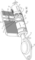
- Fig. 3A illustrates a state in which an appropriate key 65 is inserted in the key receptacle 37 of the lock core 17 and the lock core 17 is situated in a position which corresponds to a locked state of the electromechanical lock 3. Then, the projecting portion 21 of the lock bolt operating member 19 typically extends in a vertical direction.
- power is transferred to a power receiving means (not shown) of the lock core 17 for powering of the electromechanical lock cylinder 1.
- the access control device controls whether it is an appropriate key or not.
- the electric actuator 41 is activated whereby the coupling arm 43 thereof is moved from its rest position, illustrated in Fig.
- the coupling arm 43 When the coupling arm 43 is moved to the coupling position, rotation of the lock core 17 to unlock the lock 3 is thus enabled.
- the coupling arm 43 may be held in the coupling position during the complete rotation of the lock core 17 during unlocking of the lock 3 or during only an initial phase thereof. In the latter case, the coupling arm 43 need to be held in the coupling position until the retaining member 51 of the retaining device 29 has been displaced from its retaining position in the axial groove 53.
- the axial limiting device 31 serves to minimize the use of the coupling device 25. Hence, thanks to the axial limiting device 31 the electrical actuator of the coupling device 25 need to be powered only in an initial phase of the rotation of the lock core 17, i.e. under a very short period of time, which is allows for an assembly with a very low power consumption.
- the electromechanical lock cylinder 3 thus comprises an electric actuator, which may be in the form of a solenoid, to enable rotation of the lock core 17 so as to unlock the lock 3.
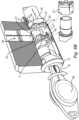
- Fig. 4A illustrates a state in which an inappropriate key 67 is inserted in the key receptacle 37 of the lock core 17 and the lock core 17 is situated in a first position which corresponds to a locked state of the electromechanical lock 3 and in which the projecting portion 21 of the lock bolt operating member 19 extends in a vertical direction.
- the access control device controls whether it is an appropriate key or not.
- the coupling device 25 is not activated.
- the coupling arm 43 then remains in the rest position which position is illustrated in Fig. 4A .
- rotation of the lock core 17 relative to the annular element 27 is possible, as illustrated by arrow F in Fig. 4B .
- Rotation of the lock core 17 relative the annular element 27 is enabled by the retainer device 29, the retaining ball 51 of which prevents the annular element 27 from rotating with the lock core 17.
- the spring biased ball 51 which is received in the axial groove 53, thus prevents the annular element 27 from rotating as the lock core 17 rotates.
- Turning of the key 67 as illustrated by arrow E in Fig. 4B , then causes the ramp surface 45 of the lock core 17 to slide against the ramp surface 47 of the annular element 27 and thereby the annular element 27 to move into engagement with the stationary blocking element 35, as illustrated by arrows G in Fig. 4B , thereby preventing further rotation of the lock core 17 in the actual direction. Unlocking of the lock 3 is then prevented.
Landscapes
- Physics & Mathematics (AREA)
- Electromagnetism (AREA)
- General Physics & Mathematics (AREA)
- Engineering & Computer Science (AREA)
- Manufacturing & Machinery (AREA)
- Computer Networks & Wireless Communication (AREA)
- Lock And Its Accessories (AREA)
Claims (12)
- Ensemble de serrure électromécanique (1), qui est configuré pour être alimenté lors de l'insertion d'une clé programmable (65) dans un réceptacle de clé (37), ledit ensemble de serrure comprenantun corps de serrure (15),un barillet (17) situé au moins partiellement à l'intérieur du corps de serrure (15) et pouvant tourner de manière sélective par rapport au corps de serrure (15), le barillet (17) comprenant un réceptacle de clé (37) pour recevoir une clé programmable (65),un élément d'actionnement de pêne de serrure (19) fixé de manière rotative au barillet (17) et configuré pour déplacer un pêne de serrure (13) d'une serrure (3) pour verrouiller et déverrouiller ladite serrure (3), etun dispositif de contrôle d'accès électronique (20) caractérisé parun élément annulaire (27) qui est monté de manière rotative et axialement déplaçable sur ledit barillet (17),un dispositif de couplage (25) agencé pour communiquer avec ledit dispositif de contrôle d'accès électronique et, lors de l'insertion d'une clé appropriée (65) dans le réceptacle de clé (37), verrouiller en rotation l'élément annulaire (27) sur le barillet (17), en permettant ainsi la rotation du barillet (17) et permettant ainsi le verrouillage et le déverrouillage dudit verrou (3) avec ladite clé appropriée (65), etun agencement de blocage (63) comprenant un dispositif de retenue (29) agencé pour empêcher ledit élément annulaire (27) de tourner avec ledit barillet (17) lorsque le barillet (17) est tourné avec une clé inappropriée (67), une surface de contact (45) située sur le barillet (17), une surface de contact (47) située sur ledit élément annulaire (27) et un élément de blocage stationnaire (35), lesdites surfaces de contact (45, 47) étant configurées pour, lors de la rotation dudit barillet (17) par rapport audit élément annulaire (27), déplacer axialement ledit élément annulaire (27) en mise en prise avec ledit élément de blocage stationnaire (35), en bloquant ainsi une rotation supplémentaire du barillet (17) et empêchant ainsi le verrouillage et le déverrouillage non autorisés ladite serrure (3).
- Ensemble de verrouillage électromécanique (1) selon la revendication 1, dans lequel ledit dispositif de couplage (25) comprend un actionneur électrique (41) agencé pour déplacer un élément de couplage (43) d'une position de repos, dans laquelle il permet au barillet (17) de tourner par rapport à l'élément annulaire (27), vers une position de couplage dans laquelle il verrouille en rotation ledit élément annulaire (27) audit barillet (17).
- Ensemble de verrouillage électromécanique (1) selon la revendication 2, dans lequel ledit élément annulaire (27) est mobile entre une position de non-blocage, vers laquelle il est sollicité par un élément de sollicitation (33), et une position de blocage.
- Ensemble de verrouillage électromécanique (1) selon une quelconque des revendications 2 à 3, dans lequel ledit élément de couplage (43) est pivotant ou rotatif entre ladite position de repos et ladite position de couplage.
- Ensemble de verrouillage (1) selon la revendication 3, dans lequel ledit élément de couplage est déplaçable linéairement entre ladite position de repos et ladite position d'accouplement.
- Ensemble de verrouillage (1) selon la revendication 2, dans lequel ledit actionneur électrique est un solénoïde.
- Ensemble de verrouillage électromécanique (1) selon une quelconque des revendications précédentes, dans lequel ledit dispositif de retenue (29) comprend un élément de retenue (51) qui est reçu dans un évidement (53) formé dans l'élément annulaire (27).
- Ensemble de verrouillage électromécanique (1) selon la revendication 7, dans lequel ledit élément de retenue est une bille (53) et de préférence une bille sollicitée par ressort (53).
- Ensemble de verrouillage électromécanique (1) selon la revendication 7, dans lequel ledit évidement est une rainure axiale (53).
- Ensemble de verrouillage électromécanique (1) selon une quelconque des revendications précédentes, dans lequel l'ensemble de verrouillage (1) comprend en outre un dispositif de limitation de mouvement axial (31) agencé pour limiter le mouvement axial de l'élément annulaire (27) par rapport à l'élément de blocage fixe (35), en empêchant ainsi l'élément annulaire d'être déplacé en prise avec l'élément de blocage fixe (35).
- Ensemble de verrouillage électromécanique (1) selon la revendication 10, dans lequel ledit dispositif de limitation de mouvement axial (31) comprend au moins une bille (59) reçue dans une rainure radiale (61) formée dans l'élément annulaire (27).
- Ensemble de verrouillage électromécanique (1) selon une quelconque des revendications précédentes, dans lequel ledit corps de verrouillage (15) est cylindrique.
Applications Claiming Priority (2)
| Application Number | Priority Date | Filing Date | Title |
|---|---|---|---|
| SE1951131A SE543627C2 (en) | 2019-10-03 | 2019-10-03 | Electromechanical lock assembly with annular element and blocking arrangement comprising a retaining device |
| PCT/SE2020/050922 WO2021066718A1 (fr) | 2019-10-03 | 2020-10-01 | Ensemble verrou électromécanique à élément annulaire, dispositifs de blocage et de retenue |
Publications (4)
| Publication Number | Publication Date |
|---|---|
| EP4038251A1 EP4038251A1 (fr) | 2022-08-10 |
| EP4038251A4 EP4038251A4 (fr) | 2023-11-01 |
| EP4038251B1 true EP4038251B1 (fr) | 2025-01-22 |
| EP4038251C0 EP4038251C0 (fr) | 2025-01-22 |
Family
ID=75336476
Family Applications (1)
| Application Number | Title | Priority Date | Filing Date |
|---|---|---|---|
| EP20871274.5A Active EP4038251B1 (fr) | 2019-10-03 | 2020-10-01 | Ensemble verrou électromécanique à élément annulaire, dispositifs de blocage et de retenue |
Country Status (4)
| Country | Link |
|---|---|
| US (1) | US12037814B2 (fr) |
| EP (1) | EP4038251B1 (fr) |
| SE (1) | SE543627C2 (fr) |
| WO (1) | WO2021066718A1 (fr) |
Family Cites Families (14)
| Publication number | Priority date | Publication date | Assignee | Title |
|---|---|---|---|---|
| DE3602989A1 (de) * | 1986-01-31 | 1987-11-19 | Herz Gmbh | Elektromechanisches schlosssystem |
| DE4416318C1 (de) * | 1994-05-09 | 1995-05-11 | Ikon Praezisionstechnik | Schloß-Schlüsselsystem |
| JP4035224B2 (ja) * | 1998-03-18 | 2008-01-16 | 株式会社ホンダロック | ステアリングロック装置 |
| DE10020038A1 (de) * | 2000-04-22 | 2001-10-25 | Winkhaus Fa August | Elektromagnetisch aktivierbarer Sperrmechanismus |
| EP1576246B1 (fr) * | 2002-12-23 | 2006-08-30 | Kaba AG | Dispositif de verrouillage |
| ITBO20030669A1 (it) | 2003-11-12 | 2005-05-13 | Cisa Spa | Gruppo antivibrazione per serratura elettrica |
| DE102005041974B3 (de) * | 2005-09-03 | 2006-12-21 | TST Tresor- und Schloßtechnik GmbH | Schliesszylinder mit Kupplung |
| BRPI0619822A2 (pt) * | 2005-12-13 | 2011-10-18 | Yebo Tech Proprietary Ltd | sistema eletromecánico de travamento |
| DE102006012196B3 (de) * | 2006-02-09 | 2007-08-02 | Iseo Serrature S.P.A., Pisogne | Schließzylinderanordnung |
| KR20080002594U (ko) | 2007-03-16 | 2008-07-14 | 주식회사 테크슈머 | 도어록 장치 |
| DE102010042486A1 (de) | 2010-10-15 | 2012-04-19 | Aug. Winkhaus Gmbh & Co. Kg | Schließzylinder |
| CA2783072C (fr) * | 2011-07-15 | 2020-02-18 | Medeco Security Locks, Inc. | Serrure a barillet amovible a fonctionnement electrique |
| TWI745456B (zh) * | 2016-10-19 | 2021-11-11 | 美商貝斯特艾瑟斯解決方案股份有限公司 | 電機式鎖芯裝置、系統及操作電機式鎖芯裝置之方法 |
| US11466473B2 (en) | 2018-04-13 | 2022-10-11 | Dormakaba Usa Inc | Electro-mechanical lock core |
-
2019
- 2019-10-03 SE SE1951131A patent/SE543627C2/en unknown
-
2020
- 2020-10-01 EP EP20871274.5A patent/EP4038251B1/fr active Active
- 2020-10-01 US US17/754,267 patent/US12037814B2/en active Active
- 2020-10-01 WO PCT/SE2020/050922 patent/WO2021066718A1/fr not_active Ceased
Also Published As
| Publication number | Publication date |
|---|---|
| EP4038251C0 (fr) | 2025-01-22 |
| EP4038251A1 (fr) | 2022-08-10 |
| EP4038251A4 (fr) | 2023-11-01 |
| US20220372795A1 (en) | 2022-11-24 |
| WO2021066718A1 (fr) | 2021-04-08 |
| US12037814B2 (en) | 2024-07-16 |
| SE1951131A1 (en) | 2021-04-04 |
| SE543627C2 (en) | 2021-04-27 |
Similar Documents
| Publication | Publication Date | Title |
|---|---|---|
| US12012775B2 (en) | Electronic lock with movable in-line locking lug | |
| US7874190B2 (en) | Electromechanical lock cylinder | |
| US11525279B2 (en) | Handle device | |
| US20080072636A1 (en) | Knob operated electromechanical lock cylinder | |
| EP3899173B1 (fr) | Ensemble serrure de porte comprenant un logement de cylindre rotatif | |
| EP4038251B1 (fr) | Ensemble verrou électromécanique à élément annulaire, dispositifs de blocage et de retenue | |
| WO2015166502A1 (fr) | Verrous communiquant avec un dispositif utilisateur pour activation | |
| US12435545B2 (en) | Locking device for a closure element | |
| DK2927399T3 (en) | Door lock unit | |
| AU2022399952B2 (en) | Electromechanical installation device for inserting into a closed cylinder-type closing device | |
| CA3238588C (fr) | Dispositif d'installation electromecanique a insertion dans un dispositif de verrouillage du type cylindre de verrouillage | |
| EP4314452B1 (fr) | Ensemble serrure électromécanique | |
| CA3239704C (fr) | Dispositif de barriere pour un element de fermeture |
Legal Events
| Date | Code | Title | Description |
|---|---|---|---|
| STAA | Information on the status of an ep patent application or granted ep patent |
Free format text: STATUS: THE INTERNATIONAL PUBLICATION HAS BEEN MADE |
|
| PUAI | Public reference made under article 153(3) epc to a published international application that has entered the european phase |
Free format text: ORIGINAL CODE: 0009012 |
|
| STAA | Information on the status of an ep patent application or granted ep patent |
Free format text: STATUS: REQUEST FOR EXAMINATION WAS MADE |
|
| 17P | Request for examination filed |
Effective date: 20220427 |
|
| AK | Designated contracting states |
Kind code of ref document: A1 Designated state(s): AL AT BE BG CH CY CZ DE DK EE ES FI FR GB GR HR HU IE IS IT LI LT LU LV MC MK MT NL NO PL PT RO RS SE SI SK SM TR |
|
| DAV | Request for validation of the european patent (deleted) | ||
| DAX | Request for extension of the european patent (deleted) | ||
| REG | Reference to a national code |
Ref country code: DE Ref legal event code: R079 Free format text: PREVIOUS MAIN CLASS: E05B0047060000 Ipc: G07C0009000000 Ref document number: 602020045316 Country of ref document: DE |
|
| A4 | Supplementary search report drawn up and despatched |
Effective date: 20230929 |
|
| RIC1 | Information provided on ipc code assigned before grant |
Ipc: E05B 47/06 20060101ALI20230925BHEP Ipc: G07C 9/00 20200101AFI20230925BHEP |
|
| RIC1 | Information provided on ipc code assigned before grant |
Ipc: E05B 47/06 20060101ALI20240717BHEP Ipc: G07C 9/00 20200101AFI20240717BHEP |
|
| GRAP | Despatch of communication of intention to grant a patent |
Free format text: ORIGINAL CODE: EPIDOSNIGR1 |
|
| STAA | Information on the status of an ep patent application or granted ep patent |
Free format text: STATUS: GRANT OF PATENT IS INTENDED |
|
| INTG | Intention to grant announced |
Effective date: 20240913 |
|
| GRAS | Grant fee paid |
Free format text: ORIGINAL CODE: EPIDOSNIGR3 |
|
| GRAA | (expected) grant |
Free format text: ORIGINAL CODE: 0009210 |
|
| STAA | Information on the status of an ep patent application or granted ep patent |
Free format text: STATUS: THE PATENT HAS BEEN GRANTED |
|
| AK | Designated contracting states |
Kind code of ref document: B1 Designated state(s): AL AT BE BG CH CY CZ DE DK EE ES FI FR GB GR HR HU IE IS IT LI LT LU LV MC MK MT NL NO PL PT RO RS SE SI SK SM TR |
|
| REG | Reference to a national code |
Ref country code: GB Ref legal event code: FG4D |
|
| REG | Reference to a national code |
Ref country code: CH Ref legal event code: EP |
|
| REG | Reference to a national code |
Ref country code: IE Ref legal event code: FG4D |
|
| REG | Reference to a national code |
Ref country code: DE Ref legal event code: R096 Ref document number: 602020045316 Country of ref document: DE |
|
| U01 | Request for unitary effect filed |
Effective date: 20250214 |
|
| U07 | Unitary effect registered |
Designated state(s): AT BE BG DE DK EE FI FR IT LT LU LV MT NL PT RO SE SI Effective date: 20250220 |
|
| PG25 | Lapsed in a contracting state [announced via postgrant information from national office to epo] |
Ref country code: RS Free format text: LAPSE BECAUSE OF FAILURE TO SUBMIT A TRANSLATION OF THE DESCRIPTION OR TO PAY THE FEE WITHIN THE PRESCRIBED TIME-LIMIT Effective date: 20250422 |
|
| PG25 | Lapsed in a contracting state [announced via postgrant information from national office to epo] |
Ref country code: PL Free format text: LAPSE BECAUSE OF FAILURE TO SUBMIT A TRANSLATION OF THE DESCRIPTION OR TO PAY THE FEE WITHIN THE PRESCRIBED TIME-LIMIT Effective date: 20250122 |
|
| PG25 | Lapsed in a contracting state [announced via postgrant information from national office to epo] |
Ref country code: ES Free format text: LAPSE BECAUSE OF FAILURE TO SUBMIT A TRANSLATION OF THE DESCRIPTION OR TO PAY THE FEE WITHIN THE PRESCRIBED TIME-LIMIT Effective date: 20250122 |
|
| PG25 | Lapsed in a contracting state [announced via postgrant information from national office to epo] |
Ref country code: IS Free format text: LAPSE BECAUSE OF FAILURE TO SUBMIT A TRANSLATION OF THE DESCRIPTION OR TO PAY THE FEE WITHIN THE PRESCRIBED TIME-LIMIT Effective date: 20250522 Ref country code: NO Free format text: LAPSE BECAUSE OF FAILURE TO SUBMIT A TRANSLATION OF THE DESCRIPTION OR TO PAY THE FEE WITHIN THE PRESCRIBED TIME-LIMIT Effective date: 20250422 |
|
| PG25 | Lapsed in a contracting state [announced via postgrant information from national office to epo] |
Ref country code: HR Free format text: LAPSE BECAUSE OF FAILURE TO SUBMIT A TRANSLATION OF THE DESCRIPTION OR TO PAY THE FEE WITHIN THE PRESCRIBED TIME-LIMIT Effective date: 20250122 |
|
| PG25 | Lapsed in a contracting state [announced via postgrant information from national office to epo] |
Ref country code: GR Free format text: LAPSE BECAUSE OF FAILURE TO SUBMIT A TRANSLATION OF THE DESCRIPTION OR TO PAY THE FEE WITHIN THE PRESCRIBED TIME-LIMIT Effective date: 20250423 |
|
| PG25 | Lapsed in a contracting state [announced via postgrant information from national office to epo] |
Ref country code: SM Free format text: LAPSE BECAUSE OF FAILURE TO SUBMIT A TRANSLATION OF THE DESCRIPTION OR TO PAY THE FEE WITHIN THE PRESCRIBED TIME-LIMIT Effective date: 20250122 |
|
| PGFP | Annual fee paid to national office [announced via postgrant information from national office to epo] |
Ref country code: GB Payment date: 20250918 Year of fee payment: 6 |
|
| PG25 | Lapsed in a contracting state [announced via postgrant information from national office to epo] |
Ref country code: CZ Free format text: LAPSE BECAUSE OF FAILURE TO SUBMIT A TRANSLATION OF THE DESCRIPTION OR TO PAY THE FEE WITHIN THE PRESCRIBED TIME-LIMIT Effective date: 20250122 |
|
| U20 | Renewal fee for the european patent with unitary effect paid |
Year of fee payment: 6 Effective date: 20250916 |
|
| PG25 | Lapsed in a contracting state [announced via postgrant information from national office to epo] |
Ref country code: SK Free format text: LAPSE BECAUSE OF FAILURE TO SUBMIT A TRANSLATION OF THE DESCRIPTION OR TO PAY THE FEE WITHIN THE PRESCRIBED TIME-LIMIT Effective date: 20250122 |
|
| PLBE | No opposition filed within time limit |
Free format text: ORIGINAL CODE: 0009261 |
|
| STAA | Information on the status of an ep patent application or granted ep patent |
Free format text: STATUS: NO OPPOSITION FILED WITHIN TIME LIMIT |
|
| 26N | No opposition filed |
Effective date: 20251023 |