EP4038263B1 - Isolement de fond de trou pour échantillonnage de fluide de formation par câble - Google Patents
Isolement de fond de trou pour échantillonnage de fluide de formation par câble Download PDFInfo
- Publication number
- EP4038263B1 EP4038263B1 EP20872813.9A EP20872813A EP4038263B1 EP 4038263 B1 EP4038263 B1 EP 4038263B1 EP 20872813 A EP20872813 A EP 20872813A EP 4038263 B1 EP4038263 B1 EP 4038263B1
- Authority
- EP
- European Patent Office
- Prior art keywords
- fluid
- wellbore
- pump
- hydrocarbon
- inlet
- Prior art date
- Legal status (The legal status is an assumption and is not a legal conclusion. Google has not performed a legal analysis and makes no representation as to the accuracy of the status listed.)
- Active
Links
Images


Classifications
-
- E—FIXED CONSTRUCTIONS
- E21—EARTH OR ROCK DRILLING; MINING
- E21B—EARTH OR ROCK DRILLING; OBTAINING OIL, GAS, WATER, SOLUBLE OR MELTABLE MATERIALS OR A SLURRY OF MINERALS FROM WELLS
- E21B49/00—Testing the nature of borehole walls; Formation testing; Methods or apparatus for obtaining samples of soil or well fluids, specially adapted to earth drilling or wells
- E21B49/08—Obtaining fluid samples or testing fluids, in boreholes or wells
- E21B49/081—Obtaining fluid samples or testing fluids, in boreholes or wells with down-hole means for trapping a fluid sample
-
- E—FIXED CONSTRUCTIONS
- E21—EARTH OR ROCK DRILLING; MINING
- E21B—EARTH OR ROCK DRILLING; OBTAINING OIL, GAS, WATER, SOLUBLE OR MELTABLE MATERIALS OR A SLURRY OF MINERALS FROM WELLS
- E21B23/00—Apparatus for displacing, setting, locking, releasing or removing tools, packers or the like in boreholes or wells
- E21B23/06—Apparatus for displacing, setting, locking, releasing or removing tools, packers or the like in boreholes or wells for setting packers
-
- E—FIXED CONSTRUCTIONS
- E21—EARTH OR ROCK DRILLING; MINING
- E21B—EARTH OR ROCK DRILLING; OBTAINING OIL, GAS, WATER, SOLUBLE OR MELTABLE MATERIALS OR A SLURRY OF MINERALS FROM WELLS
- E21B33/00—Sealing or packing boreholes or wells
- E21B33/10—Sealing or packing boreholes or wells in the borehole
- E21B33/12—Packers; Plugs
- E21B33/1208—Packers; Plugs characterised by the construction of the sealing or packing means
-
- E—FIXED CONSTRUCTIONS
- E21—EARTH OR ROCK DRILLING; MINING
- E21B—EARTH OR ROCK DRILLING; OBTAINING OIL, GAS, WATER, SOLUBLE OR MELTABLE MATERIALS OR A SLURRY OF MINERALS FROM WELLS
- E21B33/00—Sealing or packing boreholes or wells
- E21B33/10—Sealing or packing boreholes or wells in the borehole
- E21B33/12—Packers; Plugs
- E21B33/124—Units with longitudinally-spaced plugs for isolating the intermediate space
-
- E—FIXED CONSTRUCTIONS
- E21—EARTH OR ROCK DRILLING; MINING
- E21B—EARTH OR ROCK DRILLING; OBTAINING OIL, GAS, WATER, SOLUBLE OR MELTABLE MATERIALS OR A SLURRY OF MINERALS FROM WELLS
- E21B43/00—Methods or apparatus for obtaining oil, gas, water, soluble or meltable materials or a slurry of minerals from wells
- E21B43/34—Arrangements for separating materials produced by the well
- E21B43/38—Arrangements for separating materials produced by the well in the well
-
- E—FIXED CONSTRUCTIONS
- E21—EARTH OR ROCK DRILLING; MINING
- E21B—EARTH OR ROCK DRILLING; OBTAINING OIL, GAS, WATER, SOLUBLE OR MELTABLE MATERIALS OR A SLURRY OF MINERALS FROM WELLS
- E21B49/00—Testing the nature of borehole walls; Formation testing; Methods or apparatus for obtaining samples of soil or well fluids, specially adapted to earth drilling or wells
- E21B49/08—Obtaining fluid samples or testing fluids, in boreholes or wells
- E21B49/081—Obtaining fluid samples or testing fluids, in boreholes or wells with down-hole means for trapping a fluid sample
- E21B49/082—Wire-line fluid samplers
-
- E—FIXED CONSTRUCTIONS
- E21—EARTH OR ROCK DRILLING; MINING
- E21B—EARTH OR ROCK DRILLING; OBTAINING OIL, GAS, WATER, SOLUBLE OR MELTABLE MATERIALS OR A SLURRY OF MINERALS FROM WELLS
- E21B49/00—Testing the nature of borehole walls; Formation testing; Methods or apparatus for obtaining samples of soil or well fluids, specially adapted to earth drilling or wells
- E21B49/08—Obtaining fluid samples or testing fluids, in boreholes or wells
- E21B49/10—Obtaining fluid samples or testing fluids, in boreholes or wells using side-wall fluid samplers or testers
Definitions
- the present disclosure relates to methods, apparatus and systems for formation fluid sampling in wellbores.
- Formation evaluations are performed to measure and analyze the properties of the formation fluid therein, including assessing a quantity and producibility of fluids ( e . g ., oil) therein. Formation evaluations can be used to determine various actions, such as the viability of a formation for production, as well as which interval(s) of a wellbore should be targeted for production purposes.
- the ability to obtain a representative sample of formation fluid for evaluation is challenging, such as in low-permeability formations in wells that are drilled with water-based mud (WBM), including those with severe skin damage.
- WBM water-based mud
- Such wells are not uncommon in, for example, the north slope of Alaska.
- GB 2390105 describes a fluid sampling downhole tool which is positionable in a wellbore surrounded by a layer of contaminated fluid and intended to sample virgin formation fluid from beyond the layer of contaminated fluid.
- the downhole tool includes a probe engageable with a sidewall of the wellbore. Fluids flow from the formation through the probe and into the downhole tool with the virgin fluid and contaminated fluid as separate streams.
- a sampling intake is positioned within the probe and is adjusted so as to receive a portion of the stream of virgin fluid.
- US2013/0068463 describes a sampling tool which has four expandable packers spaced along its length with inlets between adjacent packers. While the two packers furthest apart are expanded, fluid from the surrounding formation is drawn into the tool. The middle pair of packers are then expanded and formation fluid flowing into the space between these two packers is collected.
- the present invention provides a method for sampling fluid from a subterranean formation that is intersected by a wellbore, the method comprising:
- a possibility, prior to isolating the section of the wellbore with the fluid tester, is to perform an initial draw-down at a target interval in the wellbore, including pumping fluid from the subterranean formation using a different (i.e. initial) fluid tester.
- the method then continues with isolating the section of the wellbore with a second fluid tester which is as stated above.
- a procedure incorporating an initial draw down followed by the method of the present invention as stated above may comprise: a) performing an initial draw-down at a first target interval in the wellbore, including pumping fluid from the subterranean formation using a first (i.e.
- Such a procedure may also include: h) determining which of the first or second target intervals to produce hydrocarbons from based on the comparison between the hydrocarbon content of the first sample and the second sample.
- the present disclosure includes methods, apparatus and systems for formation fluid sampling in wellbores.
- the methods, apparatus and systems disclosed herein provide for the segregation of formation fluid from, for example, mud filtrate, providing for relatively high-quality formation fluid samples.
- the methods, apparatus and systems disclosed herein exploit gravity and residence time within the wellbore to segregate formation fluid from other fluids.
- the methods, apparatus and systems disclosed herein provide for the selective collection of samples of the formation fluid from the well, such as by selectively pumping the formation fluid and other fluids in different directions. For example, the formation fluid may be pumped upwards, towards the opening of the wellbore, while the other fluids are pumped downwards, deeper into the wellbore.
- the methods, apparatus and systems disclosed herein include procedures, techniques, and hardware used to segregate and collect such formation fluid samples.
- Certain embodiments of the disclosure include methods for sampling formation fluid in wellbores.
- the methods include sampling formation fluid in wellbores having been drilled with water-based mud (WBM), also referred to as water mud.
- WBM water-based mud
- Water-based mud is a drilling fluid (mud) that includes water as the major liquid phase thereof, and as the wetting (external) phase thereof.
- Water-based muds can include fresh WBM, seawater WBD, lime mud, low-solids mud, low-solids/nondispersed mud (i. e., low-solids mud with no clay deflocculant chemical), potassium, and silicate.
- the methods, apparatus and systems disclosed herein include downhole fluid segregation to collect relatively high-quality formation fluid samples with wireline formation testers in wells that have been drilled with WBM and have relatively severe skin damage.
- skin is a dimensionless factor calculated to determine the production efficiency of a well by comparing actual conditions with theoretical or ideal conditions, where a positive skin value indicates some damage or influences that are impairing well productivity and a negative skin value indicates enhanced productivity, typically resulting from stimulation.
- damage refers to natural or induced production impairments that can develop in the reservoir, the near-wellbore area, the perforations, the gravel-pack completion or the production pipelines, such as the tubing.
- the methods disclosed herein are not limited to being used in the specific types of wells discussed herein (e.g., wells drilled with WBM), and may be used for the sampling of formation fluids in other types of wells.
- the formations that may be sampled using the methods disclosed herein include relatively low-permeability formations (i . e ., formations that do not readily transmit fluids, such as shales and siltstones).
- relatively low-permeability formations i . e ., formations that do not readily transmit fluids, such as shales and siltstones.
- One exemplary region in which the methods, apparatus, and systems disclosed herein may be applied is the north slope of Alaska.
- the methods disclosed herein are not limited to being used in these particular formations, and may be used in other formations for the sampling of formation fluids.
- FIGS. 1A-3C schematically depict the sampling of formation fluid within a wellbore.
- wellsite 100 is depicted, including wellbore 102 intersecting formation 104 beneath surface 106.
- Wellbore 102 may, of course, include any of various typical components of a wellbore, such as casing.
- the method includes selecting a target interval of wellbore 102 for fluid sampling.
- wellbore 102 is indicated as having three potential target intervals 108a-108c.
- target interval 108b has been selected for fluid sampling.
- the method includes subjecting the selected interval 108b of wellbore 102 to a draw-down to draw or bring a target phase into closer proximity to wellbore 102 and/or within wellbore 102. That is, fluid within the formation 104, such as oil, is sucked, pumped, or otherwise encouraged to flow from within formation 104 towards wellbore 102 and/or into cavity 110 of wellbore 102.
- a 3D radial probe such as the Saturn 3D radial probe by Schlumberger, is used to subject interval 108b to a relatively high draw-down to bring the target phase closer to or into wellbore 102.
- 3D radial probe 112 is coupled with, integrated into, or a portion of string, between upper string portion 114a and lower string portion 114b. For clarity and simplicity, the entire string is not shown.
- formation fluid 116 within interval 108b is drawn towards and/or into wellbore 102, as indicted via the arrows in FIG. 1B .
- 3D radial probe 212 includes inner bladder 296, drain assembly 294, spring loaded retract mechanism 292, and elliptical suction port 290. While the embodiment in FIG. 2 is shown as including a "spring loaded" retract mechanism, the probes disclosed herein are not limited to such a retract mechanism, and may include hydraulic retract mechanisms (e.g., including rods attached to a hydraulic mechanism) for retracting the probe or other retract mechanisms. With probe 212 positioned at the desired location within a wellbore, adjacent a target interval, inner bladder 296 is filled with fluid to expand drain assembly 294.
- elliptical suction port 290 self-seals against the adjacent formation.
- the inlets of the 3D radial probe may extend into the formation such that there is no dead space between the 3D radial probe inlet and the formation.
- Suction is then applied to the formation through elliptical suction port 290, causing filtrate and hydrocarbons to flow from formation into elliptical suction port 290; thereby, sampling formation fluids.
- Drain assembly 294 is then contracted by draining the fluid from inner bladder 296.
- Spring loaded retract mechanism 292 may be used to retract probe 212.
- the 3D radial probe 112 is shown expanded in FIG. 1C such that there is no dead volume between the inlet(s) of the probe and the walls of the wellbore 102.
- While the initial draw down of formation fluid is described as being performed with a 3D radial probe, the methods disclosed herein are not limited to use of a 3D radial probe and may use other probes or tools capable of drawing in formation fluid towards and/or into a wellbore.
- the initial drawing in of formation fluid 116 towards and/or into wellbore 102 avoids or mitigates an unfavorable mobility ratio that would, in the absence of this initial drawing of formation fluid 116, result in only invasion fluid (injectant) being moved while subsequently pumping to collect samples.
- the "mobility ratio" refers to the mobility of an injectant divided by the mobility of fluid the injectant is displacing, such as oil. Therefore, it is believed that this initial drawing in of formation fluid 116 towards and/or into wellbore 102 helps to ensure that oil is being subsequently sampled, rather than other fluids.
- Straddle packer assembly 118 includes two expandable members 120, which may be expandable via inflation, compression, swelling, or another mechanism. In FIG. 1D , straddle packing assembly 118 is shown in a non-expanded configuration. Straddle packer assembly 118 may be run into wellbore 102 on wireline, pipe or coiled tubing.
- Straddle packer assembly 118 may be a single port packer, having a single inlet for receipt of fluid therein for sampling.
- probe 112 is not shown in in conjunction with packer 118 on string 114a, 114b.
- probe 112 and packer 118 are, or at least may be, on the same tool string, and set in the toolstring in sequence.
- first probe 112 may be positioned adjacent the target interval for pumping, then probe 112 is deflated, and then packer 118 is positioned adjacent the target interval, such as by moving the tool string upwards.
- packer is inflated and pumping using packer 118 may begin.
- the fluid is pumped using two different inlets on the same toolstring ( i . e ., the inlet of probe 112 and the inlet of packer 118).
- straddle packing assembly 118 is shown in an expanded configuration, such that expandable members 120 are expanded to engage with the walls of wellbore 102. With expandable members 120 expanded, straddle packing assembly 118 isolates a section (volume) of wellbore 102 from the remainder of wellbore 102 by sealing against the sides of wellbore 102, defining isolated wellbore section 122. As shown in FIG. 1E , isolated wellbore section 122 at least partially overlaps with target interval 108b. Isolation of wellbore section 122 provides dead volume (space) for filtrate and formation fluid 116 to flow into wellbore section 122, and to segregate therein.
- the dead volume or space between the single inlet in the packer 118 and the wellbore 102 provides the space.
- Fluid 116 flows into wellbore section 122 and resides therein for a residence time, where filtrate and formation fluid separate.
- filtrate and formation fluid separate due to the immiscibility of aqueous and non-aqueous phases and/or due to the action of gravity upon the fluids. That is, the filtrate may be water-based and the formation fluid may be hydrocarbon or hydrocarbon-based, such as oil or natural gas.
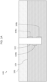
- FIG. 3A and 3B a detailed view of a portion of wellbore section 122 is shown.
- fluid mixture 124 including filtrate and formation fluid
- FIG 3B shows the same wellbore section 122, after a residence time has passed that is sufficient to allow formation fluid 116 to separate from other fluids 117.
- formation fluid 116 may be hydrocarbon or hydrocarbon-based fluid
- fluids 117 may water or water-based (e.g., WBM).
- pumping is used to encourage the flow of formation fluid 116 into wellbore section 122 during the residence time.
- water-based phase refers to a fluid ( e .
- the residence time may be provided in the annular space (wellbore section 122) to separate natural gas from water.
- the natural gas and water separate at least partially as a result of the difference in density between the natural gas and the water-phase.
- the water phase is denser than the natural gas phase, such that the water phase flows downward in wellbore 102 and the natural gas phase is segregated from the water phase and flows upward in wellbore 102.
- the residence time is provided while pumping fluid mixture 124 from formation 104. Once fluid mixture 124 enters the annular space (wellbore section 122), at least a majority of the hydrocarbon (e . g ., oil) will move upwards within wellbore section 122 due to gravity and/or immiscibility and/or density differential, and at least a majority of the WBM will move downwards, toward the inlet port of packer 118.
- the inlet port of packer 118 is positioned at 1/3 or about 1/3 of the distance between members 120 of packer, as measured from the bottom end of packer 118 ( i.e., from the top of the lower member 120).
- a sample of formation fluid 116 may be taken.
- the sample of formation fluid 116 is taken via during a rate-controlled pumping period.
- the pumping includes using a simultaneous two-pump technique to collect the segregated formation fluid and discard the mud filtrate.
- the two-pump technique may be used to pull the WBM filtrate 117 in a downward direction 301 via lower pump 305, while the hydrocarbon, formation fluid 116, is "skimmed up" using upper pump 307.
- WBM filtrate 117 is pumped downward at a high pump rate while formation fluid 116 is skimmed up in direction 303 at a low pump rate.
- the segregated hydrocarbon, formation fluid 116, is collected in sampling recipients 119 located in upper part of string 114a.
- the pump rates disclosed here are defined relative to one another. That is, the pumping of the WBM filtrate 117 via pump 305 at a "high” rate refers to the fact that the rate is higher than the rate at which the hydrocarbon is pumped via pump 307.
- the "pump rate” refers to the volumetric flow rate of the pumps.
- the two-pump technique disclosed herein exhibits a pump rate differential that is defined as the ratio of the pump rate of lower pump 305 to the pump rate of upper pump 307.
- the pump rate differential is at least 2/1 (i.e., the pump rate of lower pump 305 is at least twice that of the pump rate of upper pump 307), or at least 3/1, or at least 4/1, or at least 5/1, or at least 10/1.
- hydrocarbon While the hydrocarbon is pumped via pump 307 upwards, at least some of the hydrocarbon may still be pumped downwards along with the WBM filtrate 117.
- formation fluid 116 may be tested.
- formation fluid 116 may be tested to determine the hydrocarbon content thereof (e . g ., a weight percentage or volume percentage).
- the testing includes spectroscopy, such as fluorescence spectroscopy.
- Formation fluid 116 may be tested in real-time, simultaneously while the formation fluid 116 is being pumped and/or collected.
- formation fluid 116 may be tested using a downhole fluid analyzer, such as Schlumberger's InSitu Fluid Analyzer real-time downhole fluid analysis (DFA) system, which integrates various sensors making quantitative fluid properties measurements to provide a comprehensive characterization of formation fluid 116 at reservoir conditions.
- DFA downhole fluid analysis
- both fluid streams flowing upward (fluid stream 311 in FIG. 3C ) and flowing downward (fluid stream 313 in FIG. 3C ) are scanned by downhole fluid analyzers 319 (shown in FIG. 3C ) to obtain fluid fraction information therefrom.
- the scanning of fluid streams 311 and 313 is performed continuously or continually.
- the fluid fraction information e . g ., percentage of hydrocarbon and/or water
- the fluid fraction information is interpreted from the data collected by analyzers 119 in real-time (continuously or continually) to determine the optimum time to collect fluid samples therefrom.
- the combination of tool inlets i.e ., the inlets of probe 112 and that of packer 118 used in the present method, both with dead volume (i.e ., packer 118) and without dead volume ( i . e ., probe 112), can assist to displace the mud filtrate 117, bring the target phase (formation fluid 116) closer to the wellbore 102, and allow for collection of relatively high-quality samples after the formation fluid 116 is segregated via the action of gravity at the wellbore 102.
- the cleanup period that the annular space between the packer 118 and the wellbore 102 (i.e., the space defined by isolated wellbore section 122) provides a sufficient residence time to both phases of the fluid therein, such that the isolated wellbore section 122 acts as a segregation chamber for the fluid.
- "Cleanup” refers to a period when fluids are coming out of the formation and into the wellbore. During this time, the skin effect changes, such that well test results may reflect temporary obstructions to flow that will not be present in later tests.
- the ability to segregate the WBM from the formation fluid provides for more accurate determinations of the fluid contents of the wellbore and intervals thereof. More accurate determinations of the fluid contents provide for the ability to determine which wellbores and which intervals thereof are more viable for hydrocarbon production.
- the present disclosure provides for the use of downhole residence time, using a wellbore coupled with dual pump action, to separate hydrocarbons from WBM filtrate through a single probe inlet. Without being bound by theory, it is believed that embodiments of the sampling techniques disclosed herein, including those using current formation tester capabilities, are capable of collecting relatively high-quality samples in wells where such high-quality sample collection has previously been thought to be challenging or impossible. Formation testers include tools run on wireline to obtain fluid samples and measure formation pressures.
- Formation testers are sometimes referred to as wireline formation testers. Formation testers include tool run on an electric logging cable that push probes into the formation, which then allows production into a closed chamber. While formation fluid is discussed herein as including oil, formation fluid may include any fluid that occurs in the pores of a rock, including oil, natural gas and water.
- the methods disclosed herein have been described with reference to obtaining and analyzing fluid samples in wells drilled using WBM, the methods disclosed herein are not limited to such wells.
- Oil-based mud is an invert-emulsion mud, or an emulsion whose continuous phase is oil.
- the same method and procedure nay be implemented to obtain and test samples of fluid, with the exception that the fluid flowing downwards ( e . g ., fluid stream 313 in FIG. 3C ) is collected instead of the fluid flowing upwards ( e . g ., fluid stream 311 in FIG. 3C ).
- FIGS. 4A-4C depict sequential sections of one exemplary downhole string, from a top end 402 of string 414 to a bottom end 404 of string 414.
- String 414 includes sample capture sections 419a-419c, pump 407 for pumping at a relatively a low pump rate, 3D radial probe 412, straddle packer 418, and pump 405 for pumping at a relatively high pump rate.
- String 414 is shown in sections for clarity. However, it would be clear to one skilled in the art that string 414 is a unified structure, with the sections shown in FIGS. 4A-4C connected together.
- FIG. 4D depicts a simplified schematic of a string including the various components that may be used to implement the methods disclosed herein.
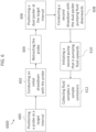
- FIG. 5 depicts an exemplary flow chart of a method for sampling formation fluid using a two-step process ( i . e ., using a first probe for an initial drawdown, and then using a second, different probe for a subsequent pumping stage).
- Fluid sampling method 5000 includes conducting an initial draw-down 500 at a target interval in a wellbore. For example, a 3D radial probe may be lowered on a wireline into the wellbore to intersect the target interval, and may be activated to draw in formation fluids from the formation into the wellbore.
- Fluid sampling method 5000 includes retracting probe 502.
- Fluid sampling method 5000 includes isolating a wellbore interval 504 that is at least partially coincident with the target interval.
- Fluid sampling method 5000 includes provide a residence time 506, such that the formation fluid can separate from the WBM due to gravity and/or immiscibility and/or density differential. Fluid sampling method 5000 includes pumping the fluids, 508. For example, the separated formation fluid can be pumped upwards and the WBM can be pumped downwards. Fluid sampling method 5000 includes collecting samples of the formation fluid, 510. Fluid sampling method 5000 includes testing the formation fluid 512. For example, the formation fluid can be tested to determine the hydrocarbon content thereof.
- FIG. 6 depicts another exemplary flow chart of a method for sampling formation fluid using a two-step process.
- Fluid sampling method 6000 includes positioning a probe at a target interval, 600.
- a 3D radial probe such as a Saturn Probe
- Fluid sampling method 6000 includes conducting an initial drawdown with the probe, 602.
- a Saturn Probe may be used, with a single pump, to pump fluid either upwards or downwards in the wellbore.
- Fluid sampling method 6000 includes retracting the probe, 604.
- Fluid sampling method 6000 includes positioning a dual packer at the target interval, 606.
- Fluid sampling method 6000 includes conducting a second drawdown with the dual packer pumping fluid downwards, 608.
- the dual packer may use a single pump to pump fluid downwards at a first pump rate.
- the phases of the fluid will segregate in the annular space of the dual packer during the pumping. In some applications it only takes seconds (less than one minute) for segregation to occur.
- FIG. 5 includes providing a residence time for segregation as a separate step, this step may occur simultaneously and coincidently with the pumping.
- Fluid sampling method 6000 includes initiating a second pump that is pumping fluid upwards, 610. The second pump pumps fluid upwards at a slower pump rate than does the first pump.
- Fluid sampling method 6000 includes collecting fluid samples in sample containers, 612.
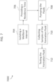
- FIG. 7 depicts an exemplary flow chart of a method for sampling formation fluid using a one-step process ( i . e ., using a single probe for both initial drawdown and subsequent pumping/sampling stage).
- Fluid sampling method 7000 includes isolating a wellbore interval 704 that is at least partially coincident with the target interval. For example, a straddle packer assembly may be used to isolate the wellbore interval.
- Fluid sampling method 7000 includes provide a residence time 706, such that the formation fluid can separate from the WBM due to gravity and immiscibility.
- Fluid sampling method 7000 includes pumping the fluids, 708. For example, the separated formation fluid can be pumped upwards and the WBM can be pumped downwards.
- Fluid sampling method 7000 includes collecting samples of the formation fluid, 710.
- Fluid sampling method 7000 includes testing the formation fluid 712. For example, the formation fluid can be tested to determine the hydrocarbon content thereof.
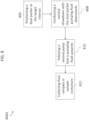
- FIG. 8 depicts another exemplary flow chart of a method for sampling formation fluid using a one-step process.
- Fluid sampling method 8000 includes positioning a dual packer at the target interval, 806.
- Fluid sampling method 8000 includes conducting a second drawdown with the dual packer pumping fluid downwards, 808.
- the dual packer may use a single pump to pump fluid downwards at a first pump rate.
- the phases of the fluid will segregate in the annular space of the dual packer during the pumping. In some applications it only takes seconds (less than one minute) for segregation to occur.
- FIG. 7 includes providing a residence time for segregation as a separate step, this step may occur simultaneously and coincidently with the pumping.
- Fluid sampling method 8000 includes initiating a second pump that is pumping fluid upwards, 810.
- the second pump pumps fluid upwards at a slower pump rate than does the first pump.
- Fluid sampling method 8000 includes collecting fluid samples in sample containers, 812.
- FIGS. 5-8 depicts several exemplary methods. However, the method disclosed herein is not limited to being implemented using these exact steps is the exact orders as shown in FIGS. 5-8 . Certain steps may be eliminated, certain steps may be added, certain steps may occur at least partially coincident with other steps, and the order of certain steps may be rearranged.
- a two-step process in used to take and analyze fluid samples, such as is shown in FIGS. 5 and 6 .
- an initial pump e.g., using a Saturn probe
- a second pump with the target interval isolated (e . g ., using a straddle packer).
- a two-step process reduces the time that it takes to bring the target hydrocarbon phase into the wellbore to obtain and analyze fluid samples, in comparison to a one-step process.
- a one-step process is used to obtain and analyze fluid samples, such as is shown in FIGS. 7 and 8 .
- the initial pumping to bring the target hydrocarbon phase into the wellbore and the subsequent pumping to obtain and analyze fluid samples is conducted using the same fluid tester ( e.g ., using a straddle packer).
- the methods, apparatus, and systems disclosed herein may be used to collect samples of formation fluid.
- the methods, apparatus, and systems disclosed herein may be used to collect fluid samples in wells in relatively low-permeability formations that have been drilled with WBM, including those with severe skin damage.
- the methods, apparatus, and systems disclosed herein may be used to collect samples of formation fluid form wells on the north slope of Alaska.
- fluid sampling method disclosed herein may be used to assess the quantity and producibility of fluids from a reservoir. Information obtained from such fluid sampling methods may be used to guide wellsite decisions, such as placement of perforations and hydraulic fracture stages, and reservoir development and production planning.
- the fluid samples taken in accordance with the present disclosure exhibit an increase in hydrocarbon fraction, relative to the hydrocarbon fraction in samples taken without providing a residence time to the fluid within an isolated dead volume prior to sampling.
- the hydrocarbon fraction of the fluid samples is increased from a percentage that is less than 50%, or less than 40%, or less than 30%, or less than 20%, or less than 10%, or 5% or less to a percentage that is at least 50%, at least 60%, or least 70%, at least 80%, at least 90%, or at least 95% (where each % is a weight percent, wt.%).
- the hydrocarbon fraction of a fluid sample is increased by a factor of 20. That is, the measured hydrocarbon percentage of a fluid may be 4.5 wt.% when using a probe that has no dead volume, but the measured hydrocarbon percentage measured of the same fluid may be 90 wt.% when subsequently using a probe with dead volume that provides residence time to the fluid prior to sampling. In some such embodiments, the hydrocarbon fraction of the fluid samples is increased by a factor of 20, 18, 15, 12, 10, 8, 5, or 2.
- a maximum hydrocarbon fraction in a fluid sample may be 5 wt.% when using probes that have no dead volume, whereas, samples from the same well may have hydrocarbon fractions increased to 90 wt.% by subsequently using probes with dead volume that provide residence time to the fluids prior to sampling with the pumps.
- the annular space between the tool (the straddle packer) and the wellbore was acting as a segregation chamber for the fluid therein.
- Lab results confirmed that the fluid samples collected without residence time contained 95 wt.% WBM filtrate, while the bottles (samples) collected with the proposed technique, utilizing the residence time, contained 90 wt.% hydrocarbon.
- the methods disclosed herein may be used to collect relatively high-quality fluid samples with wireline formation testers in wells drilled with WBM having severe skin damage.
Landscapes
- Life Sciences & Earth Sciences (AREA)
- Engineering & Computer Science (AREA)
- Geology (AREA)
- Mining & Mineral Resources (AREA)
- Physics & Mathematics (AREA)
- Environmental & Geological Engineering (AREA)
- Fluid Mechanics (AREA)
- General Life Sciences & Earth Sciences (AREA)
- Geochemistry & Mineralogy (AREA)
- Sampling And Sample Adjustment (AREA)
Claims (14)
- Procédé destiné à l'échantillonnage de fluide provenant d'une formation souterraine (104) qui est traversée par un puits de forage (102), le procédé comprenant :l'isolation d'une section (122) du puits de forage avec un testeur de fluide, le testeur de fluide comportant une entrée (123), dans lequel l'isolation de la section du puits de forage avec le testeur de fluide comporte la fourniture d'un espace entre l'entrée du testeur de fluide et la formation souterraine (104) ;le pompage d'un mélange de fluides (124) provenant de la formation souterraine (104) dans le puits de forage et dans l'entrée du testeur de fluides,caractérisé en ce quele testeur de fluide comprend une garniture double (118) présentant deux éléments expansibles (120) qui sont espacés l'un de l'autre et l'entrée (123) du testeur de fluide est positionnée entre les éléments expansibles ;l'isolation de la section (122) du puits de forage comprend l'expansion des éléments expansibles de la garniture double pour isoler un volume mort à l'intérieur du puits de forage entre les éléments expansibles (120) et, lorsque les éléments expansibles sont expansés, le volume mort fournit l'espace entre l'entrée de la garniture double et la formation souterraine ;dans lequel, pendant le pompage, le mélange de fluides (124) qui pénètre dans le volume mort à partir de la formation se sépare au moins partiellement dans le volume mort en au moins deux phases, lesdites au moins deux phases comportant une phase à base d'hydrocarbures et une phase à base d'eau ;lorsque les phases à base d'hydrocarbures et à base d'eau entrent dans l'entrée du testeur de fluide, le pompage d'un échantillon d'au moins une partie de la phase à base d'hydrocarbures (116) avec une première pompe (307) depuis l'entrée du testeur de fluide vers une chambre d'échantillonnage et l'utilisation d'une seconde pompe (305) pour pomper le reste du fluide (117) depuis l'entrée du testeur de fluide dans le puits de forage (102), dans lequel la seconde pompe (305) présentant un débit de pompage plus élevé que le débit de pompage de la première pompe (307) ; et le test de la teneur en hydrocarbures de l'échantillon.
- Procédé selon la revendication 1, dans lequel la garniture double comporte une seule entrée (123).
- Procédé selon la revendication 1 ou la revendication 2 comprenant en outre, avant l'isolation de la section (122) du puits de forage avec le testeur de fluide, le pompage du fluide depuis la formation souterraine (104) à la section du puits de forage dans un testeur de fluide initial (112) à travers une entrée (290) de celui-ci.
- Procédé selon la revendication 3, dans lequel le testeur de fluide initial comprend une sonde radiale en 3D (112).
- Procédé selon la revendication 3 ou la revendication 4, dans lequel il n'y a pas de volume mort entre l'entrée (290) du testeur de fluide initial (112) et la formation souterraine (104) pendant le pompage dans le testeur de fluide initial.
- Procédé selon l'une quelconque des revendications 2 à 5, dans lequel la teneur en hydrocarbures du fluide pompé par le testeur de fluide initial (112) est inférieure à 50 % en poids.
- Procédé selon une quelconque revendication précédente, dans lequel l'échantillon est pompé vers le haut en direction de la surface du puits de forage et le reste du fluide est pompé vers le bas dans le puits de forage.
- Procédé selon une quelconque revendication précédente, dans lequel une teneur en hydrocarbures de l'échantillon est d'au moins 50 %.
- Procédé selon une quelconque revendication précédente, dans lequel une teneur en hydrocarbures de l'échantillon est d'au moins 90 %.
- Procédé selon une quelconque revendication précédente, dans lequel le volume mort agit comme une chambre de ségrégation de sorte que le mélange de fluides s'y sépare par l'intermédiaire de la gravité, de l'immiscibilité entre l'hydrocarbure et l'eau, des différences de densité entre l'hydrocarbure et l'eau, ou des combinaisons de ces facteurs, en une seule phase à base d'hydrocarbures (116) et une seule phase à base d'eau (117), la phase à base d'hydrocarbure se trouvant au-dessus de la phase à base d'eau.
- Procédé selon une quelconque revendication précédente, dans lequel l'échantillon est écrémé à partir d'une partie supérieure du fluide entrant dans le testeur de fluide et pompé par l'intermédiaire de la première pompe.
- Procédé selon une quelconque revendication précédente, dans lequel le débit de pompage de la seconde pompe (305) est au moins 2 fois supérieur au débit de pompage de la première pompe (307).
- Procédé selon une quelconque revendication précédente, dans lequel le débit de pompage de la seconde pompe (305) est au moins 5 fois supérieur au débit de pompage de la première pompe (307).
- Procédé selon une quelconque revendication précédente, dans lequel le pompage de la première pompe (307) et le pompage de la seconde pompe (305) sont effectués simultanément.
Applications Claiming Priority (2)
| Application Number | Priority Date | Filing Date | Title |
|---|---|---|---|
| US201962908958P | 2019-10-01 | 2019-10-01 | |
| PCT/US2020/053740 WO2021067561A1 (fr) | 2019-10-01 | 2020-10-01 | Isolement de fond de trou pour échantillonnage de fluide de formation par câble |
Publications (3)
| Publication Number | Publication Date |
|---|---|
| EP4038263A1 EP4038263A1 (fr) | 2022-08-10 |
| EP4038263A4 EP4038263A4 (fr) | 2023-09-06 |
| EP4038263B1 true EP4038263B1 (fr) | 2024-08-07 |
Family
ID=75337506
Family Applications (1)
| Application Number | Title | Priority Date | Filing Date |
|---|---|---|---|
| EP20872813.9A Active EP4038263B1 (fr) | 2019-10-01 | 2020-10-01 | Isolement de fond de trou pour échantillonnage de fluide de formation par câble |
Country Status (3)
| Country | Link |
|---|---|
| US (2) | US12123302B2 (fr) |
| EP (1) | EP4038263B1 (fr) |
| WO (1) | WO2021067561A1 (fr) |
Families Citing this family (1)
| Publication number | Priority date | Publication date | Assignee | Title |
|---|---|---|---|---|
| US12258859B1 (en) | 2023-10-30 | 2025-03-25 | Halliburton Energy Services, Inc. | Continuous separation of multi-phase formation fluids during downhole sampling and measuring |
Citations (1)
| Publication number | Priority date | Publication date | Assignee | Title |
|---|---|---|---|---|
| US20140224474A1 (en) * | 2013-02-14 | 2014-08-14 | Baker Hughes Incorporated | Apparatus and Method for Obtaining Formation Samples Utilizing Independently Controlled Devices on a Common Hydraulic Line |
Family Cites Families (17)
| Publication number | Priority date | Publication date | Assignee | Title |
|---|---|---|---|---|
| US5540280A (en) * | 1994-08-15 | 1996-07-30 | Halliburton Company | Early evaluation system |
| US6722432B2 (en) * | 2001-01-29 | 2004-04-20 | Schlumberger Technology Corporation | Slimhole fluid tester |
| US7178591B2 (en) | 2004-08-31 | 2007-02-20 | Schlumberger Technology Corporation | Apparatus and method for formation evaluation |
| US6964301B2 (en) * | 2002-06-28 | 2005-11-15 | Schlumberger Technology Corporation | Method and apparatus for subsurface fluid sampling |
| CA2447306C (fr) | 2002-11-01 | 2009-05-12 | Ecl Group Of Companies Ltd. | Fluide de packer |
| US7906023B2 (en) * | 2005-01-25 | 2011-03-15 | Pss Acquisitionco Llc | Wastewater treatment method and apparatus |
| CA2620050C (fr) * | 2006-07-21 | 2010-11-16 | Halliburton Energy Services, Inc. | Dispositif d'isolation a volume variable forme de packers et procede d'echantillonnage associe |
| CA2667523C (fr) * | 2006-10-25 | 2013-04-30 | Schlumberger Canada Limited | Estimation de grande precision d'une contamination d'echantillons d'hydrocarbures au moyen de la technique gc x gc |
| EA016847B1 (ru) * | 2007-12-17 | 2012-07-30 | Эм-Ай ЭлЭлСи | Система и способ отделения углеводородов |
| EP2313610B1 (fr) | 2008-07-14 | 2012-10-17 | Schlumberger Technology B.V. | Instrument et procédé d évaluation de formations |
| US8905130B2 (en) | 2011-09-20 | 2014-12-09 | Schlumberger Technology Corporation | Fluid sample cleanup |
| US9845673B2 (en) * | 2014-06-11 | 2017-12-19 | Schlumberger Technology Corporation | System and method for controlled pumping in a downhole sampling tool |
| WO2017040457A2 (fr) * | 2015-08-31 | 2017-03-09 | Weatherford Technology Holdings, Llc | Essai transitoire de succion à débit multiple |
| US11125081B2 (en) * | 2016-10-31 | 2021-09-21 | Schlumberger Technology Corporation | Terminal modules for downhole formation testing tools |
| US11827837B2 (en) * | 2019-04-02 | 2023-11-28 | King Fahd University Of Petroleum And Minerals | Water-based drilling, completion, and workover fluid composition with reduced barite sagging |
| WO2021015747A1 (fr) * | 2019-07-23 | 2021-01-28 | Halliburton Energy Services, Inc. | Détermination d'une composition de boue de forage |
| EP3789580B1 (fr) * | 2019-09-04 | 2024-07-03 | Schlumberger Technology B.V. | Détermination des caractéristiques de ressources d'hydrocarbures via une diagraphie de boue |
-
2020
- 2020-10-01 EP EP20872813.9A patent/EP4038263B1/fr active Active
- 2020-10-01 WO PCT/US2020/053740 patent/WO2021067561A1/fr not_active Ceased
- 2020-10-01 US US17/754,390 patent/US12123302B2/en active Active
-
2024
- 2024-10-18 US US18/919,585 patent/US12560083B2/en active Active
Patent Citations (1)
| Publication number | Priority date | Publication date | Assignee | Title |
|---|---|---|---|---|
| US20140224474A1 (en) * | 2013-02-14 | 2014-08-14 | Baker Hughes Incorporated | Apparatus and Method for Obtaining Formation Samples Utilizing Independently Controlled Devices on a Common Hydraulic Line |
Also Published As
| Publication number | Publication date |
|---|---|
| US20250043682A1 (en) | 2025-02-06 |
| US12123302B2 (en) | 2024-10-22 |
| US12560083B2 (en) | 2026-02-24 |
| WO2021067561A1 (fr) | 2021-04-08 |
| EP4038263A1 (fr) | 2022-08-10 |
| EP4038263A4 (fr) | 2023-09-06 |
| US20220341318A1 (en) | 2022-10-27 |
Similar Documents
| Publication | Publication Date | Title |
|---|---|---|
| US7703517B2 (en) | Downhole sampling tool and method for using same | |
| AU2004218736B2 (en) | Downhole sampling apparatus and method for using same | |
| US7380599B2 (en) | Apparatus and method for characterizing a reservoir | |
| US8991245B2 (en) | Apparatus and methods for characterizing a reservoir | |
| US8397817B2 (en) | Methods for downhole sampling of tight formations | |
| US10480316B2 (en) | Downhole fluid analysis methods for determining viscosity | |
| US9759055B2 (en) | Formation fracturing and sampling methods | |
| US11125083B2 (en) | Focused formation sampling method and apparatus | |
| US8905130B2 (en) | Fluid sample cleanup | |
| US12560083B2 (en) | Downhole segregation for wireline formation fluid sampling | |
| US20150176405A1 (en) | Packer Tool Including Multiple Ports For Selective Guarding And Sampling | |
| US2935133A (en) | Formation testing | |
| EP3117070B1 (fr) | Soupape à manchon coulissant de réalisation de puits, basée sur un système et un procédé d'échantillonnage | |
| EP2706191A2 (fr) | Minimisation d'impuretés dans une chambre d'échantillons | |
| Galvan-Sanchez et al. | The effects of repeated interruptions during the clean-up cycle in a challenging logging-while-drilling sampling operation |
Legal Events
| Date | Code | Title | Description |
|---|---|---|---|
| STAA | Information on the status of an ep patent application or granted ep patent |
Free format text: STATUS: THE INTERNATIONAL PUBLICATION HAS BEEN MADE |
|
| PUAI | Public reference made under article 153(3) epc to a published international application that has entered the european phase |
Free format text: ORIGINAL CODE: 0009012 |
|
| STAA | Information on the status of an ep patent application or granted ep patent |
Free format text: STATUS: REQUEST FOR EXAMINATION WAS MADE |
|
| 17P | Request for examination filed |
Effective date: 20220401 |
|
| AK | Designated contracting states |
Kind code of ref document: A1 Designated state(s): AL AT BE BG CH CY CZ DE DK EE ES FI FR GB GR HR HU IE IS IT LI LT LU LV MC MK MT NL NO PL PT RO RS SE SI SK SM TR |
|
| DAV | Request for validation of the european patent (deleted) | ||
| DAX | Request for extension of the european patent (deleted) | ||
| A4 | Supplementary search report drawn up and despatched |
Effective date: 20230809 |
|
| RIC1 | Information provided on ipc code assigned before grant |
Ipc: E21B 43/38 20060101ALI20230803BHEP Ipc: E21B 33/124 20060101ALI20230803BHEP Ipc: E21B 23/06 20060101ALI20230803BHEP Ipc: E21B 33/12 20060101ALI20230803BHEP Ipc: E21B 43/12 20060101ALI20230803BHEP Ipc: E21B 49/08 20060101AFI20230803BHEP |
|
| STAA | Information on the status of an ep patent application or granted ep patent |
Free format text: STATUS: EXAMINATION IS IN PROGRESS |
|
| GRAP | Despatch of communication of intention to grant a patent |
Free format text: ORIGINAL CODE: EPIDOSNIGR1 |
|
| STAA | Information on the status of an ep patent application or granted ep patent |
Free format text: STATUS: GRANT OF PATENT IS INTENDED |
|
| 17Q | First examination report despatched |
Effective date: 20240409 |
|
| INTG | Intention to grant announced |
Effective date: 20240426 |
|
| GRAS | Grant fee paid |
Free format text: ORIGINAL CODE: EPIDOSNIGR3 |
|
| GRAA | (expected) grant |
Free format text: ORIGINAL CODE: 0009210 |
|
| STAA | Information on the status of an ep patent application or granted ep patent |
Free format text: STATUS: THE PATENT HAS BEEN GRANTED |
|
| AK | Designated contracting states |
Kind code of ref document: B1 Designated state(s): AL AT BE BG CH CY CZ DE DK EE ES FI FR GB GR HR HU IE IS IT LI LT LU LV MC MK MT NL NO PL PT RO RS SE SI SK SM TR |
|
| REG | Reference to a national code |
Ref country code: GB Ref legal event code: FG4D |
|
| REG | Reference to a national code |
Ref country code: CH Ref legal event code: EP |
|
| REG | Reference to a national code |
Ref country code: IE Ref legal event code: FG4D |
|
| REG | Reference to a national code |
Ref country code: DE Ref legal event code: R096 Ref document number: 602020035531 Country of ref document: DE |
|
| REG | Reference to a national code |
Ref country code: LT Ref legal event code: MG9D |
|
| REG | Reference to a national code |
Ref country code: NL Ref legal event code: MP Effective date: 20240807 |
|
| REG | Reference to a national code |
Ref country code: AT Ref legal event code: MK05 Ref document number: 1711144 Country of ref document: AT Kind code of ref document: T Effective date: 20240807 |
|
| PG25 | Lapsed in a contracting state [announced via postgrant information from national office to epo] |
Ref country code: PT Free format text: LAPSE BECAUSE OF FAILURE TO SUBMIT A TRANSLATION OF THE DESCRIPTION OR TO PAY THE FEE WITHIN THE PRESCRIBED TIME-LIMIT Effective date: 20241209 Ref country code: NL Free format text: LAPSE BECAUSE OF FAILURE TO SUBMIT A TRANSLATION OF THE DESCRIPTION OR TO PAY THE FEE WITHIN THE PRESCRIBED TIME-LIMIT Effective date: 20240807 Ref country code: FI Free format text: LAPSE BECAUSE OF FAILURE TO SUBMIT A TRANSLATION OF THE DESCRIPTION OR TO PAY THE FEE WITHIN THE PRESCRIBED TIME-LIMIT Effective date: 20240807 Ref country code: PL Free format text: LAPSE BECAUSE OF FAILURE TO SUBMIT A TRANSLATION OF THE DESCRIPTION OR TO PAY THE FEE WITHIN THE PRESCRIBED TIME-LIMIT Effective date: 20240807 Ref country code: GR Free format text: LAPSE BECAUSE OF FAILURE TO SUBMIT A TRANSLATION OF THE DESCRIPTION OR TO PAY THE FEE WITHIN THE PRESCRIBED TIME-LIMIT Effective date: 20241108 |
|
| PG25 | Lapsed in a contracting state [announced via postgrant information from national office to epo] |
Ref country code: BG Free format text: LAPSE BECAUSE OF FAILURE TO SUBMIT A TRANSLATION OF THE DESCRIPTION OR TO PAY THE FEE WITHIN THE PRESCRIBED TIME-LIMIT Effective date: 20240807 |
|
| PG25 | Lapsed in a contracting state [announced via postgrant information from national office to epo] |
Ref country code: LV Free format text: LAPSE BECAUSE OF FAILURE TO SUBMIT A TRANSLATION OF THE DESCRIPTION OR TO PAY THE FEE WITHIN THE PRESCRIBED TIME-LIMIT Effective date: 20240807 |
|
| PG25 | Lapsed in a contracting state [announced via postgrant information from national office to epo] |
Ref country code: AT Free format text: LAPSE BECAUSE OF FAILURE TO SUBMIT A TRANSLATION OF THE DESCRIPTION OR TO PAY THE FEE WITHIN THE PRESCRIBED TIME-LIMIT Effective date: 20240807 Ref country code: IS Free format text: LAPSE BECAUSE OF FAILURE TO SUBMIT A TRANSLATION OF THE DESCRIPTION OR TO PAY THE FEE WITHIN THE PRESCRIBED TIME-LIMIT Effective date: 20241207 |
|
| PG25 | Lapsed in a contracting state [announced via postgrant information from national office to epo] |
Ref country code: HR Free format text: LAPSE BECAUSE OF FAILURE TO SUBMIT A TRANSLATION OF THE DESCRIPTION OR TO PAY THE FEE WITHIN THE PRESCRIBED TIME-LIMIT Effective date: 20240807 |
|
| PG25 | Lapsed in a contracting state [announced via postgrant information from national office to epo] |
Ref country code: RS Free format text: LAPSE BECAUSE OF FAILURE TO SUBMIT A TRANSLATION OF THE DESCRIPTION OR TO PAY THE FEE WITHIN THE PRESCRIBED TIME-LIMIT Effective date: 20241107 Ref country code: ES Free format text: LAPSE BECAUSE OF FAILURE TO SUBMIT A TRANSLATION OF THE DESCRIPTION OR TO PAY THE FEE WITHIN THE PRESCRIBED TIME-LIMIT Effective date: 20240807 |
|
| PG25 | Lapsed in a contracting state [announced via postgrant information from national office to epo] |
Ref country code: RS Free format text: LAPSE BECAUSE OF FAILURE TO SUBMIT A TRANSLATION OF THE DESCRIPTION OR TO PAY THE FEE WITHIN THE PRESCRIBED TIME-LIMIT Effective date: 20241107 Ref country code: PT Free format text: LAPSE BECAUSE OF FAILURE TO SUBMIT A TRANSLATION OF THE DESCRIPTION OR TO PAY THE FEE WITHIN THE PRESCRIBED TIME-LIMIT Effective date: 20241209 Ref country code: PL Free format text: LAPSE BECAUSE OF FAILURE TO SUBMIT A TRANSLATION OF THE DESCRIPTION OR TO PAY THE FEE WITHIN THE PRESCRIBED TIME-LIMIT Effective date: 20240807 Ref country code: NL Free format text: LAPSE BECAUSE OF FAILURE TO SUBMIT A TRANSLATION OF THE DESCRIPTION OR TO PAY THE FEE WITHIN THE PRESCRIBED TIME-LIMIT Effective date: 20240807 Ref country code: LV Free format text: LAPSE BECAUSE OF FAILURE TO SUBMIT A TRANSLATION OF THE DESCRIPTION OR TO PAY THE FEE WITHIN THE PRESCRIBED TIME-LIMIT Effective date: 20240807 Ref country code: IS Free format text: LAPSE BECAUSE OF FAILURE TO SUBMIT A TRANSLATION OF THE DESCRIPTION OR TO PAY THE FEE WITHIN THE PRESCRIBED TIME-LIMIT Effective date: 20241207 Ref country code: HR Free format text: LAPSE BECAUSE OF FAILURE TO SUBMIT A TRANSLATION OF THE DESCRIPTION OR TO PAY THE FEE WITHIN THE PRESCRIBED TIME-LIMIT Effective date: 20240807 Ref country code: GR Free format text: LAPSE BECAUSE OF FAILURE TO SUBMIT A TRANSLATION OF THE DESCRIPTION OR TO PAY THE FEE WITHIN THE PRESCRIBED TIME-LIMIT Effective date: 20241108 Ref country code: FI Free format text: LAPSE BECAUSE OF FAILURE TO SUBMIT A TRANSLATION OF THE DESCRIPTION OR TO PAY THE FEE WITHIN THE PRESCRIBED TIME-LIMIT Effective date: 20240807 Ref country code: ES Free format text: LAPSE BECAUSE OF FAILURE TO SUBMIT A TRANSLATION OF THE DESCRIPTION OR TO PAY THE FEE WITHIN THE PRESCRIBED TIME-LIMIT Effective date: 20240807 Ref country code: BG Free format text: LAPSE BECAUSE OF FAILURE TO SUBMIT A TRANSLATION OF THE DESCRIPTION OR TO PAY THE FEE WITHIN THE PRESCRIBED TIME-LIMIT Effective date: 20240807 Ref country code: AT Free format text: LAPSE BECAUSE OF FAILURE TO SUBMIT A TRANSLATION OF THE DESCRIPTION OR TO PAY THE FEE WITHIN THE PRESCRIBED TIME-LIMIT Effective date: 20240807 |
|
| PG25 | Lapsed in a contracting state [announced via postgrant information from national office to epo] |
Ref country code: DK Free format text: LAPSE BECAUSE OF FAILURE TO SUBMIT A TRANSLATION OF THE DESCRIPTION OR TO PAY THE FEE WITHIN THE PRESCRIBED TIME-LIMIT Effective date: 20240807 Ref country code: SM Free format text: LAPSE BECAUSE OF FAILURE TO SUBMIT A TRANSLATION OF THE DESCRIPTION OR TO PAY THE FEE WITHIN THE PRESCRIBED TIME-LIMIT Effective date: 20240807 |
|
| PG25 | Lapsed in a contracting state [announced via postgrant information from national office to epo] |
Ref country code: EE Free format text: LAPSE BECAUSE OF FAILURE TO SUBMIT A TRANSLATION OF THE DESCRIPTION OR TO PAY THE FEE WITHIN THE PRESCRIBED TIME-LIMIT Effective date: 20240807 |
|
| PG25 | Lapsed in a contracting state [announced via postgrant information from national office to epo] |
Ref country code: CZ Free format text: LAPSE BECAUSE OF FAILURE TO SUBMIT A TRANSLATION OF THE DESCRIPTION OR TO PAY THE FEE WITHIN THE PRESCRIBED TIME-LIMIT Effective date: 20240807 |
|
| PG25 | Lapsed in a contracting state [announced via postgrant information from national office to epo] |
Ref country code: SK Free format text: LAPSE BECAUSE OF FAILURE TO SUBMIT A TRANSLATION OF THE DESCRIPTION OR TO PAY THE FEE WITHIN THE PRESCRIBED TIME-LIMIT Effective date: 20240807 |
|
| REG | Reference to a national code |
Ref country code: DE Ref legal event code: R119 Ref document number: 602020035531 Country of ref document: DE |
|
| REG | Reference to a national code |
Ref country code: CH Ref legal event code: PL |
|
| PLBE | No opposition filed within time limit |
Free format text: ORIGINAL CODE: 0009261 |
|
| STAA | Information on the status of an ep patent application or granted ep patent |
Free format text: STATUS: NO OPPOSITION FILED WITHIN TIME LIMIT |
|
| PG25 | Lapsed in a contracting state [announced via postgrant information from national office to epo] |
Ref country code: MC Free format text: LAPSE BECAUSE OF FAILURE TO SUBMIT A TRANSLATION OF THE DESCRIPTION OR TO PAY THE FEE WITHIN THE PRESCRIBED TIME-LIMIT Effective date: 20240807 |
|
| PG25 | Lapsed in a contracting state [announced via postgrant information from national office to epo] |
Ref country code: DE Free format text: LAPSE BECAUSE OF NON-PAYMENT OF DUE FEES Effective date: 20250501 |
|
| PG25 | Lapsed in a contracting state [announced via postgrant information from national office to epo] |
Ref country code: BE Free format text: LAPSE BECAUSE OF NON-PAYMENT OF DUE FEES Effective date: 20241031 Ref country code: LU Free format text: LAPSE BECAUSE OF NON-PAYMENT OF DUE FEES Effective date: 20241001 |
|
| 26N | No opposition filed |
Effective date: 20250508 |
|
| PG25 | Lapsed in a contracting state [announced via postgrant information from national office to epo] |
Ref country code: FR Free format text: LAPSE BECAUSE OF NON-PAYMENT OF DUE FEES Effective date: 20241007 |
|
| PG25 | Lapsed in a contracting state [announced via postgrant information from national office to epo] |
Ref country code: CH Free format text: LAPSE BECAUSE OF NON-PAYMENT OF DUE FEES Effective date: 20241031 |
|
| REG | Reference to a national code |
Ref country code: BE Ref legal event code: MM Effective date: 20241031 |
|
| PG25 | Lapsed in a contracting state [announced via postgrant information from national office to epo] |
Ref country code: SE Free format text: LAPSE BECAUSE OF FAILURE TO SUBMIT A TRANSLATION OF THE DESCRIPTION OR TO PAY THE FEE WITHIN THE PRESCRIBED TIME-LIMIT Effective date: 20240807 |
|
| PGFP | Annual fee paid to national office [announced via postgrant information from national office to epo] |
Ref country code: TR Payment date: 20250930 Year of fee payment: 6 |
|
| PGFP | Annual fee paid to national office [announced via postgrant information from national office to epo] |
Ref country code: GB Payment date: 20250821 Year of fee payment: 6 |
|
| PG25 | Lapsed in a contracting state [announced via postgrant information from national office to epo] |
Ref country code: IE Free format text: LAPSE BECAUSE OF NON-PAYMENT OF DUE FEES Effective date: 20241001 |
|
| PG25 | Lapsed in a contracting state [announced via postgrant information from national office to epo] |
Ref country code: RO Free format text: LAPSE BECAUSE OF FAILURE TO SUBMIT A TRANSLATION OF THE DESCRIPTION OR TO PAY THE FEE WITHIN THE PRESCRIBED TIME-LIMIT Effective date: 20240807 |
|
| PGFP | Annual fee paid to national office [announced via postgrant information from national office to epo] |
Ref country code: NO Payment date: 20251009 Year of fee payment: 6 |
|
| PG25 | Lapsed in a contracting state [announced via postgrant information from national office to epo] |
Ref country code: IT Free format text: LAPSE BECAUSE OF FAILURE TO SUBMIT A TRANSLATION OF THE DESCRIPTION OR TO PAY THE FEE WITHIN THE PRESCRIBED TIME-LIMIT Effective date: 20240807 Ref country code: CY Free format text: LAPSE BECAUSE OF FAILURE TO SUBMIT A TRANSLATION OF THE DESCRIPTION OR TO PAY THE FEE WITHIN THE PRESCRIBED TIME-LIMIT; INVALID AB INITIO Effective date: 20201001 |
|
| PG25 | Lapsed in a contracting state [announced via postgrant information from national office to epo] |
Ref country code: HU Free format text: LAPSE BECAUSE OF FAILURE TO SUBMIT A TRANSLATION OF THE DESCRIPTION OR TO PAY THE FEE WITHIN THE PRESCRIBED TIME-LIMIT; INVALID AB INITIO Effective date: 20201001 |