EP4038281B1 - Buchsenrückhaltesystem - Google Patents
Buchsenrückhaltesystem Download PDFInfo
- Publication number
- EP4038281B1 EP4038281B1 EP20789224.1A EP20789224A EP4038281B1 EP 4038281 B1 EP4038281 B1 EP 4038281B1 EP 20789224 A EP20789224 A EP 20789224A EP 4038281 B1 EP4038281 B1 EP 4038281B1
- Authority
- EP
- European Patent Office
- Prior art keywords
- bush
- retention member
- holder
- recesses
- recess
- Prior art date
- Legal status (The legal status is an assumption and is not a legal conclusion. Google has not performed a legal analysis and makes no representation as to the accuracy of the status listed.)
- Active
Links
Images


Classifications
-
- F—MECHANICAL ENGINEERING; LIGHTING; HEATING; WEAPONS; BLASTING
- F04—POSITIVE - DISPLACEMENT MACHINES FOR LIQUIDS; PUMPS FOR LIQUIDS OR ELASTIC FLUIDS
- F04C—ROTARY-PISTON, OR OSCILLATING-PISTON, POSITIVE-DISPLACEMENT MACHINES FOR LIQUIDS; ROTARY-PISTON, OR OSCILLATING-PISTON, POSITIVE-DISPLACEMENT PUMPS
- F04C15/00—Component parts, details or accessories of machines, pumps or pumping installations, not provided for in groups F04C2/00 - F04C14/00
- F04C15/0057—Driving elements, brakes, couplings, transmission specially adapted for machines or pumps
- F04C15/0061—Means for transmitting movement from the prime mover to driven parts of the pump, e.g. clutches, couplings, transmissions
- F04C15/0069—Magnetic couplings
-
- F—MECHANICAL ENGINEERING; LIGHTING; HEATING; WEAPONS; BLASTING
- F16—ENGINEERING ELEMENTS AND UNITS; GENERAL MEASURES FOR PRODUCING AND MAINTAINING EFFECTIVE FUNCTIONING OF MACHINES OR INSTALLATIONS; THERMAL INSULATION IN GENERAL
- F16C—SHAFTS; FLEXIBLE SHAFTS; ELEMENTS OR CRANKSHAFT MECHANISMS; ROTARY BODIES OTHER THAN GEARING ELEMENTS; BEARINGS
- F16C17/00—Sliding-contact bearings for exclusively rotary movement
- F16C17/10—Sliding-contact bearings for exclusively rotary movement for both radial and axial load
- F16C17/102—Sliding-contact bearings for exclusively rotary movement for both radial and axial load with grooves in the bearing surface to generate hydrodynamic pressure
- F16C17/107—Sliding-contact bearings for exclusively rotary movement for both radial and axial load with grooves in the bearing surface to generate hydrodynamic pressure with at least one surface for radial load and at least one surface for axial load
-
- F—MECHANICAL ENGINEERING; LIGHTING; HEATING; WEAPONS; BLASTING
- F16—ENGINEERING ELEMENTS AND UNITS; GENERAL MEASURES FOR PRODUCING AND MAINTAINING EFFECTIVE FUNCTIONING OF MACHINES OR INSTALLATIONS; THERMAL INSULATION IN GENERAL
- F16B—DEVICES FOR FASTENING OR SECURING CONSTRUCTIONAL ELEMENTS OR MACHINE PARTS TOGETHER, e.g. NAILS, BOLTS, CIRCLIPS, CLAMPS, CLIPS OR WEDGES; JOINTS OR JOINTING
- F16B21/00—Means for preventing relative axial movement of a pin, spigot, shaft or the like and a member surrounding it; Stud-and-socket releasable fastenings
- F16B21/10—Means for preventing relative axial movement of a pin, spigot, shaft or the like and a member surrounding it; Stud-and-socket releasable fastenings by separate parts
- F16B21/16—Means for preventing relative axial movement of a pin, spigot, shaft or the like and a member surrounding it; Stud-and-socket releasable fastenings by separate parts with grooves or notches in the pin or shaft
- F16B21/18—Means for preventing relative axial movement of a pin, spigot, shaft or the like and a member surrounding it; Stud-and-socket releasable fastenings by separate parts with grooves or notches in the pin or shaft with circlips or like resilient retaining devices, i.e. resilient in the plane of the ring or the like; Details
-
- F—MECHANICAL ENGINEERING; LIGHTING; HEATING; WEAPONS; BLASTING
- F04—POSITIVE - DISPLACEMENT MACHINES FOR LIQUIDS; PUMPS FOR LIQUIDS OR ELASTIC FLUIDS
- F04D—NON-POSITIVE-DISPLACEMENT PUMPS
- F04D29/00—Details, component parts, or accessories
- F04D29/04—Shafts or bearings, or assemblies thereof
- F04D29/046—Bearings
-
- F—MECHANICAL ENGINEERING; LIGHTING; HEATING; WEAPONS; BLASTING
- F16—ENGINEERING ELEMENTS AND UNITS; GENERAL MEASURES FOR PRODUCING AND MAINTAINING EFFECTIVE FUNCTIONING OF MACHINES OR INSTALLATIONS; THERMAL INSULATION IN GENERAL
- F16C—SHAFTS; FLEXIBLE SHAFTS; ELEMENTS OR CRANKSHAFT MECHANISMS; ROTARY BODIES OTHER THAN GEARING ELEMENTS; BEARINGS
- F16C17/00—Sliding-contact bearings for exclusively rotary movement
- F16C17/10—Sliding-contact bearings for exclusively rotary movement for both radial and axial load
-
- F—MECHANICAL ENGINEERING; LIGHTING; HEATING; WEAPONS; BLASTING
- F16—ENGINEERING ELEMENTS AND UNITS; GENERAL MEASURES FOR PRODUCING AND MAINTAINING EFFECTIVE FUNCTIONING OF MACHINES OR INSTALLATIONS; THERMAL INSULATION IN GENERAL
- F16C—SHAFTS; FLEXIBLE SHAFTS; ELEMENTS OR CRANKSHAFT MECHANISMS; ROTARY BODIES OTHER THAN GEARING ELEMENTS; BEARINGS
- F16C33/00—Parts of bearings; Special methods for making bearings or parts thereof
- F16C33/02—Parts of sliding-contact bearings
- F16C33/04—Brasses; Bushes; Linings
-
- F—MECHANICAL ENGINEERING; LIGHTING; HEATING; WEAPONS; BLASTING
- F04—POSITIVE - DISPLACEMENT MACHINES FOR LIQUIDS; PUMPS FOR LIQUIDS OR ELASTIC FLUIDS
- F04C—ROTARY-PISTON, OR OSCILLATING-PISTON, POSITIVE-DISPLACEMENT MACHINES FOR LIQUIDS; ROTARY-PISTON, OR OSCILLATING-PISTON, POSITIVE-DISPLACEMENT PUMPS
- F04C2240/00—Components
- F04C2240/50—Bearings
- F04C2240/56—Bearing bushings or details thereof
Definitions
- This invention relates to a bushing system and in particular to a bushing system which can be used in a magnetic drive or canned motor pump
- Magnetic drive pumps for example the CSA/CSI pump from the applicant being a typical example, are required to operate over a wide range of application temperatures.
- the stator part of a magnetic drive pump bearing system typically comprises a structural metal housing and bearing material bushes - typically silicon carbide or carbon, although other materials are sometimes employed.
- the bush parts are typically interference fitted into the structural metallic bush housing. This achieves several purposes - (i) the bushes are rigidly fixed and retained in the structural housing, (ii) the bushes are prevented from rotating, in reacting the rotation of the rotor part(s), and (iii) the bush material is good in compression, but may crack in tension and so interference fitting the bush into a bush holder ensures that the bush stays compressed.
- interference fitted bush system construction includes (a) a wide range of metallurgies and/or interference fits have to be employed to cater for process liquid compatibility and differences in application temperature ranges, respectively, for example, variations in material coefficient of thermal expansion between the bushes and bush holder have to be accounted for in the design of the interference fits, and (b) interference fitting these parts together requires specialist equipment and is extremely difficult to facilitate in the field, should a breakdown occur.
- US9353752 discloses an electrical submersible pump assembly includes a centrifugal pump having impellers and diffusers. A thrust runner is coupled to a motor shaft for rotation along with the impellers.
- CN208348303 discloses an oil-free bushing having a fixing seat, a bushing and two annular retaining rings.
- a similar bushing system is also known from US 2019/277006 A1 .
- a bushing system for use in a magnetic drive or canned motor pump, the system comprising a bush holder having an axial recess for receiving a bush, a bush for insertion into the axial recess, the bush and bush holder each having: one or more cooperating features which abut against each other when the bush is fitted into the recess; characterised in that the bush and bush holder each have a recess for receiving at least part of a retention member; wherein, when the cooperating features abut, the retention member recesses on the bush holder and the bush are axially offset.
- the cooperating features preferably includes one or more shoulders.
- the retention member recesses are preferably axially misaligned.
- the retention member recesses may overlap in the axial direction.
- One or both retention member recesses are preferably annular.
- the retention member recess in the bush holder may be axially further than the retention member recess in the bush from the cooperating features.
- the system above may further comprise a retention member.
- the retention member may be compliant.
- the retention member and the axially offset recesses may combine to provide a biasing force which urges the bush and bush holder towards each other.
- the bush and bush holder preferably each have one or more axially extending mating surfaces which are in contact when the bush is inserted in the bush holder.
- the mating surfaces are preferably complementary to limit relative rotation of the bush and bush holder.
- the mating surfaces are preferably configured such that they prevent relative rotation of the bush and bush holder.
- each mating surface preferably matches the opposite surface exactly.
- One or more of the retention member recesses may be annular.
- One or more of the retention member recesses may be partially circumferential.
- One or more of the retention member recesses may be arcuate sections.
- Multiple retention member recesses may be provided on one or both of the bush and bush holder.
- the retention member may be toroidal in shape.
- the retention member may have a circular, square, parallelogram or hexagonal cross-section.
- Figure 1 shows the three individual components that form the bush retention system 10.
- the three components are a bush 11, a bush holder 12 and a retention member 13.
- the left-hand half of Figure 1 shows the components 11,12 and 13 as an axial section, and the right-hand half of Figure 1 shows an outer view of the solid component.
- Bush 11 has a main body section 20 which is generally cylindrical in form with, at the upper end in Figure 1 , a wider flange section 21.
- the flange need not be at an end, but it is generally preferable that it is at an end.
- the flange and main body section define a shoulder 22 therebetween.
- the shoulder 22 includes a chamfered section 23, in this case a curve which may have a relatively small radius of curvature when compared to the diameter of the main body section.
- the chamfer may take an alternative form including one or more straight sections. The chamfer may be omitted and the flange 21 and main body section 20 could meet a hard angle, such as a right angle.
- the main body section 20 of bush 11 defines an axially extending passageway 24.
- the passageway will typically, as in this example, extend all the way through the bush such that it takes the form of an open passageway.
- the passageway is typically of a constant cross section, both in shape and size.
- the recess/passageway 24 is for receiving in use a shaft which is intended to rotate with the bush 11.
- the passageway 24 is generally circular in cross section and is defined by an inner surface 26 of a wall 27 which forms the main body section 20.
- the wall 26 has an outer surface 28.
- One or more (three in this case at equally spaced radial positions) axially extending recesses or indents 29 are formed in the inner surface 26 and these are always open at each end to permit liquid to flow along the inner surface 26.
- the main body section 20 includes a retention member recess 25 formed in the outer surface 28.
- the recess may have a curved cross-section, which may be a complete semi-circle or may only be arcuate.
- the cross section is preferably constant along the entire length of the recess.
- Alternative cross sections are possible and may be dependent upon the size and/or shape of retention member 13 being used.
- the recess 25 extends all the way around the main body section 20.
- the main body section 20 is substantially circular in cross section, and thus the recess 25 is circular.
- the recess may not be a single recess extending all the way round the main body section, but instead may be two or more partially circumferential recesses. These may be evenly spaced around the main body section.
- Bush holder 12 is typically a structural component, usually formed from a metallic material (typically stainless steel 316L).
- the bush holder 12 is formed by a wall 30 having inner 31 and outer 32 surfaces.
- An axially extending passage 33 passes axially from one end to the other (normally, at the other end, a matching formation is provided for receiving another bush 11).
- the outer surface 32 of the wall 30 is stepped in several locations to aid the location of the bush holder within other components.
- the upper (in the figures) end 36 of the bush holder 12 has a larger diameter than other portions of the holder 20, thereby defining a bush holder neck 34.
- the upper end 36 of the passageway 34 in bush holder 12 is intended to receive the lower end of bush 20.
- the inner surface of the wall 30 is formed with a pair of shoulders/seats 35, 38.
- a bush holder shoulder 35 is formed toward the upper end of the inner surface of wall 30.
- the shoulder 35 may be identical in size and/or shape to the shoulder 23 of the bush 11 such that, when the bush is inserted into the bush holder, shoulder 23 rests on shoulder 35.
- the shoulder 35 may take a different shape and/or size, for example a 45 degree angled surface relative to the curve of shoulder 23, so as to act as a lead-in so the retention member 13 can more easily slide into the bore of the bush holder.
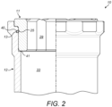
- Seat 38 in the bush holder is preferably positioned, as can be seen in Fig 2 , such that when the bush has been inserted into the bush holder, there is a small gap between seat 38 and the lower most surface of the bush 11, so that the axial bearing load is reacted by shoulder 35.
- a bush holder retention recess 40 is formed axially between the shoulder 35 and seat 38.
- the recess may have a curved cross-section, which may be a complete semi-circle or may only be arcuate.
- the cross section is preferably constant along the entire length of the recess.
- Alternative cross sections are possible and may be dependent upon the size and/or shape of retention member 12 being used.
- the recess 40 extends all the way around the inner surface 31.
- the inner surface 31 is substantially circular in cross section, and thus the recess 40 is circular.
- the recess may not be a single recess extending all the way round the main body section, but instead may be two or more partially circumferential recesses. These may be evenly spaced around the main body section.
- the partial recesses of the bush holder are preferably located at the same circumferential positions as any partial recesses in the bush 11.
- Retention member 13 typically takes the form of an o-ring as these are commonly available and easy install, especially as there is no specific orientation required.
- the retention member may have a different cross section.
- the shape of the cross section of the retention member may correspond to the recesses, i.e. an o-ring would typically have semi-circular/arcuate cross section recesses, a square cross section retention member would typically have square/rectangular recesses.
- the retention member 13 is preferably formed from a compliant material.
- the retention member When the retention member extends around the full circumference of the bush main body 20, it may additionally act as a seal, e.g to prevent liquid traveling across the axial or radial bearing surfaces and lubricates the axial and radial 'bearings' respectively from short-circuit the bearing system by travelling along the clearance gap between the bore of the bush-holder and the outside diameter of the bush.
- the compliant material may be an elastomer (e.g. FKM, FFKM, EPDM, etc) or a thermosetting plastic (e.g. PTFE, nylon, etc) depending on process liquid compatibility.
- the range of retention materials which can be employed not only caters for a wide range of process liquid chemical compatibilities, but also enables the 'spring stiffness' of the journal bearing system to be optimised by the choice of the most appropriate material.
- a circlip or other appropriate device could be used in place of an o-ring.
- FIG. 2 shows the bush 11, bush holder 12 and bush retention member 13 in a constructed arrangement in which the shoulder 23 and shoulder 35 abut. It can be seen that the bush retention recess 23 and the bush holder retention recess 40 are at different axial positions, i.e. they are axially misaligned or offset. In particular, bush retention recess 25 is located axially closer than the bush holder retention recess 40 to the flange 21. This axially misalignment means that the retention member 13 causes a biasing force to be applied between the bush 11 and the bush holder 12, such that the two components are urged axially towards each other into face to face contact.
- the bush 11 in the example, extends out of the upper end 36 of the bush holder 12, so as to prevent the rotor part of the bearing reacting with the stainless steel bush-holder, as opposed to the silicon carbide bush, causing wearing, particulate and damage.
- the lowermost end of the bush 11 is axially spaced from the seat 38 in the bush holder 12 thereby defining an annular gap 41.
- the retention member also serves to centre the bush 11 in relation to the bush holder 12 and provides stiffness and a radial compressive load to the bush.
- the use of the retention member with the axial offset allows the bush and bush holder faces to be presented in the optimum position with no distortion (such as dishing or coning) of the faces due to the interference fitting of the parts. This results in improved operation, that would be expected to give longer life as a consequence.
- the fitting diameter of the bush 11 is preferably a clearance fit to the bush holder bore 33. This eliminates the need for an interference fitting operation and the specialist (heating) equipment that this involves. It can also mean that the retrofit operation becomes a simple push fit of one component into another, an operation that is more conducive to field servicing of magnetic drive pumps. Finally, it also reduces the number of permutations of bush to bush holder fits that are needed to cover a wide range of duty temperatures, thereby allowing one bush holder size to fit all applications, simplifying manufacture, stocking and supply of spare parts.
- Figure 3 illustrates a further feature of the bush and bush holder fitting.
- the engagement between the bush 11 and the bush holder 12 features an anti-rotation system 50 whereby a flat edge 51 on the outside diameter of the bush 11 (typically on the flange 21), fits to a corresponding flat feature 52 milled into the end of the inner surface 31 of the bush holder 12.
- Anti-rotation features often require a separate part, e.g. a pin, wire, circlip, etc., which can shake loose and again requires different metallurgies for the sake of chemical compatibility with the process liquid.
- the integration of the flat feature into the bearing system provides an anti-rotation method that is simple, effective and further reduces the 'parts-count'.
Landscapes
- Engineering & Computer Science (AREA)
- General Engineering & Computer Science (AREA)
- Mechanical Engineering (AREA)
- Physics & Mathematics (AREA)
- Fluid Mechanics (AREA)
- Sliding-Contact Bearings (AREA)
Claims (15)
- Buchsensystem zur Verwendung in einer magnetgetriebenen oder Spaltrohrmotorpumpe, wobei das System Folgendes umfasst:einen Buchsenhalter (12), der eine axiale Aussparung zum Aufnehmen einer Buchse aufweist,eine Buchse (11) zum Einsetzen in die axiale Aussparung, wobei die Buchse und der Buchsenhalter jeweils Folgendes aufweisen:ein oder mehrere zusammenwirkende Merkmale (23, 35), die aneinander anliegen, wenn die Buchse in die axiale Aussparung eingepasst ist; dadurch gekennzeichnet, dassdie Buchse und der Buchsenhalter jeweils eine Aussparung (25, 40) zum Aufnehmen mindestens eines Teils eines Rückhalteelements (13) aufweisen;wobei, wenn die zusammenwirkenden Merkmale aneinander anliegen, die Rückhalteelementaussparungen (25, 40) an dem Buchsenhalter und der Buchse axial versetzt sind.
- System nach Anspruch 1, wobei die zusammenwirkenden Merkmale einen oder mehrere Absätze enthalten.
- System nach Anspruch 1 oder Anspruch 2, wobei die Rückhalteelementaussparungen axial nicht fluchtend sind.
- System nach Anspruch 3, wobei sich die Rückhalteelementaussparungen in axialer Richtung überlappen.
- System nach einem der vorhergehenden Ansprüche, wobei eine oder beide Rückhalteelementaussparungen ringförmig sind.
- System nach einem der vorhergehenden Ansprüche, wobei die Rückhalteelementaussparung in dem Buchsenhalter axial weiter von den zusammenwirkenden Merkmalen entfernt ist als die Rückhalteelementaussparung in der Buchse.
- System nach einem der vorhergehenden Ansprüche, ferner ein Rückhalteelement umfassend, wobei das Rückhalteelement nachgiebig ist.
- System nach Anspruch 7, wobei das Rückhalteelement und die axial versetzten Aussparungen zusammen eine Vorspannkraft bereitstellen, die die Buchse und den Buchsenhalter aufeinander zu drückt.
- System nach einem der vorhergehenden Ansprüche, wobei die Buchse und der Buchsenhalter jeweils eine oder mehrere sich axial erstreckende Passoberflächen aufweisen, die in Kontakt sind, wenn die Buchse in den Buchsenhalter eingesetzt ist.
- System nach Anspruch 9, wobei die Passoberflächen komplementär sind, um eine relative Drehung der Buchse und des Buchsenhalters zu begrenzen.
- System nach Anspruch 10, wobei die Passoberflächen dazu konfiguriert sind, eine relative Drehung der Buchse und des Buchsenhalters zu verhindern.
- System nach Anspruch 11, wobei ein Abschnitt jeder Passoberfläche genau mit der gegenüberliegenden Oberfläche übereinstimmt.
- System nach einem der vorhergehenden Ansprüche, wobei eine oder mehrere der Rückhalteelementaussparungen ringförmig sind.
- System nach einem der Ansprüche 1 bis 12, wobei eine oder mehrere der Rückhalteelementaussparungen teilweise umlaufend oder bogenförmige Querschnitte sind.
- System nach einem der vorhergehenden Ansprüche, wobei mehrere Rückhalteelementaussparungen an einer oder beiden von der Buchse und dem Buchsenhalter bereitgestellt sind.
Applications Claiming Priority (2)
| Application Number | Priority Date | Filing Date | Title |
|---|---|---|---|
| GB1914171.2A GB2587808B (en) | 2019-10-01 | 2019-10-01 | Bush retention system |
| PCT/GB2020/052406 WO2021064404A1 (en) | 2019-10-01 | 2020-10-01 | Bush retention system |
Publications (2)
| Publication Number | Publication Date |
|---|---|
| EP4038281A1 EP4038281A1 (de) | 2022-08-10 |
| EP4038281B1 true EP4038281B1 (de) | 2024-12-04 |
Family
ID=68538861
Family Applications (1)
| Application Number | Title | Priority Date | Filing Date |
|---|---|---|---|
| EP20789224.1A Active EP4038281B1 (de) | 2019-10-01 | 2020-10-01 | Buchsenrückhaltesystem |
Country Status (5)
| Country | Link |
|---|---|
| US (1) | US12435746B2 (de) |
| EP (1) | EP4038281B1 (de) |
| ES (1) | ES3009888T3 (de) |
| GB (1) | GB2587808B (de) |
| WO (1) | WO2021064404A1 (de) |
Families Citing this family (1)
| Publication number | Priority date | Publication date | Assignee | Title |
|---|---|---|---|---|
| MX2025009174A (es) * | 2024-08-19 | 2026-04-01 | Roper Pump Company Llc | Rodamientos de deslizamiento con brida para uso prolongado |
Citations (1)
| Publication number | Priority date | Publication date | Assignee | Title |
|---|---|---|---|---|
| US20190277006A1 (en) * | 2018-03-12 | 2019-09-12 | Caterpillar Inc. | Dragline Oval Two-Piece Bushing |
Family Cites Families (15)
| Publication number | Priority date | Publication date | Assignee | Title |
|---|---|---|---|---|
| US4351450A (en) * | 1981-06-08 | 1982-09-28 | General Motors Corporation | Groove structure for a retaining ring |
| GB2256248A (en) * | 1991-05-30 | 1992-12-02 | Michael Craig Broadbent | Blind fastener |
| IT1289779B1 (it) * | 1996-12-20 | 1998-10-16 | Skf Ind Spa | Dispositivo di bloccaggio reversibile di un gruppo omocinetico sul proprio mozzo, particolarmente per un autoveicolo. |
| DE10015911B4 (de) * | 2000-03-30 | 2006-06-29 | Zf Sachs Ag | Axiale Sicherung zweier Bauteile mit einem Sicherungsring |
| JP4555096B2 (ja) * | 2005-01-13 | 2010-09-29 | 株式会社パイオラックス | 保持部材、軸及びスナップリングの組付構造 |
| JP4964417B2 (ja) * | 2005-01-28 | 2012-06-27 | Ntn株式会社 | 等速ジョイントのシャフト抜け防止構造 |
| JP2006258254A (ja) * | 2005-03-18 | 2006-09-28 | Ntn Corp | 等速ジョイントのシャフト抜け防止構造 |
| DE102008031394A1 (de) * | 2007-07-26 | 2009-03-19 | Bf New Technologies Gmbh | Verbindungsanordnung und Gelenkwelle hiermit |
| DE202012009001U1 (de) * | 2012-09-19 | 2014-01-15 | Bümach Engineering International B.V. | Arbeitszylinder |
| DE202012008999U1 (de) * | 2012-09-19 | 2014-01-15 | Bümach Engineering International B.V. | Kolbeneinheit eines Arbeitszylinders |
| US9353752B2 (en) * | 2013-07-19 | 2016-05-31 | Baker Hughes Incorporated | Compliant abrasion resistant bearings for a submersible well pump |
| DE102014008719B3 (de) * | 2014-06-18 | 2015-07-16 | Ifa-Technologies Gmbh | Verbindungsanordnung zur Axialsicherung einer Welle-Nabe-Verbindung und Verfahren zur Axialsicherung einer Welle-Nabe-Verbindung |
| JP6717647B2 (ja) * | 2016-04-18 | 2020-07-01 | 日立オートモティブシステムズ株式会社 | プロペラシャフト |
| US10138943B2 (en) * | 2016-05-05 | 2018-11-27 | Ford Global Technologies, Llc | Drivetrain component connecting system |
| CN208348303U (zh) * | 2018-06-11 | 2019-01-08 | 东莞怡合达自动化股份有限公司 | 无油衬套 |
-
2019
- 2019-10-01 GB GB1914171.2A patent/GB2587808B/en active Active
-
2020
- 2020-10-01 EP EP20789224.1A patent/EP4038281B1/de active Active
- 2020-10-01 ES ES20789224T patent/ES3009888T3/es active Active
- 2020-10-01 WO PCT/GB2020/052406 patent/WO2021064404A1/en not_active Ceased
- 2020-10-01 US US17/766,165 patent/US12435746B2/en active Active
Patent Citations (1)
| Publication number | Priority date | Publication date | Assignee | Title |
|---|---|---|---|---|
| US20190277006A1 (en) * | 2018-03-12 | 2019-09-12 | Caterpillar Inc. | Dragline Oval Two-Piece Bushing |
Also Published As
| Publication number | Publication date |
|---|---|
| GB201914171D0 (en) | 2019-11-13 |
| GB2587808A (en) | 2021-04-14 |
| WO2021064404A1 (en) | 2021-04-08 |
| EP4038281A1 (de) | 2022-08-10 |
| US20220372974A1 (en) | 2022-11-24 |
| ES3009888T3 (en) | 2025-03-31 |
| US12435746B2 (en) | 2025-10-07 |
| GB2587808B (en) | 2023-09-13 |
Similar Documents
| Publication | Publication Date | Title |
|---|---|---|
| US20100148448A1 (en) | Pump seal | |
| EP3469240B1 (de) | Rotierende gleitringdichtung mit ladung einer magnetischen zugvorrichtung | |
| US6376952B1 (en) | Bearing system for a rotating shaft | |
| AU2014264822B2 (en) | Pump arrangement comprising a plain bearing arrangement | |
| US9845808B2 (en) | Spherical sleeve and bushing bearing for centrifugal pump stage | |
| GB2576124A (en) | Compliant abrasion resistant bearings for a submersible well pump | |
| US4415167A (en) | Assembled multi-component seal | |
| US20200240522A1 (en) | Slip ring sealing arrangement and slip ring sealing kit | |
| US12435746B2 (en) | Bush retention system | |
| CN101939552B (zh) | 泵机组 | |
| CN103415715B (zh) | 流体动力滑动轴承 | |
| US11415144B2 (en) | Compliant keyway for an electric submersible pump bearing sleeve | |
| US3417704A (en) | Centrifugal pump having an impeller shaft mounted on a rotating bearing | |
| CN105121922B (zh) | 用于流体机械的滑环、轴、机械密封件、壳体和转子以及流体机械 | |
| US10330107B2 (en) | Drive rotor for a magnetically coupled pump having tolerance rings | |
| US11773702B2 (en) | Motor bearing with anti-rotation spring for electrical submersible well pump | |
| KR20240004667A (ko) | 캔드 모터 펌프의 베어링 구조 | |
| US20250075702A1 (en) | Multistage centrifugal pump for pumping fluid, an impeller/ shaft assembly and a method for assembling an impeller/ shaft assembly | |
| NL1013213C2 (nl) | Glijringafdichting. |
Legal Events
| Date | Code | Title | Description |
|---|---|---|---|
| STAA | Information on the status of an ep patent application or granted ep patent |
Free format text: STATUS: UNKNOWN |
|
| STAA | Information on the status of an ep patent application or granted ep patent |
Free format text: STATUS: THE INTERNATIONAL PUBLICATION HAS BEEN MADE |
|
| PUAI | Public reference made under article 153(3) epc to a published international application that has entered the european phase |
Free format text: ORIGINAL CODE: 0009012 |
|
| STAA | Information on the status of an ep patent application or granted ep patent |
Free format text: STATUS: REQUEST FOR EXAMINATION WAS MADE |
|
| 17P | Request for examination filed |
Effective date: 20220330 |
|
| AK | Designated contracting states |
Kind code of ref document: A1 Designated state(s): AL AT BE BG CH CY CZ DE DK EE ES FI FR GB GR HR HU IE IS IT LI LT LU LV MC MK MT NL NO PL PT RO RS SE SI SK SM TR |
|
| DAV | Request for validation of the european patent (deleted) | ||
| DAX | Request for extension of the european patent (deleted) | ||
| P01 | Opt-out of the competence of the unified patent court (upc) registered |
Effective date: 20230419 |
|
| GRAP | Despatch of communication of intention to grant a patent |
Free format text: ORIGINAL CODE: EPIDOSNIGR1 |
|
| STAA | Information on the status of an ep patent application or granted ep patent |
Free format text: STATUS: GRANT OF PATENT IS INTENDED |
|
| INTG | Intention to grant announced |
Effective date: 20240625 |
|
| GRAS | Grant fee paid |
Free format text: ORIGINAL CODE: EPIDOSNIGR3 |
|
| GRAA | (expected) grant |
Free format text: ORIGINAL CODE: 0009210 |
|
| STAA | Information on the status of an ep patent application or granted ep patent |
Free format text: STATUS: THE PATENT HAS BEEN GRANTED |
|
| AK | Designated contracting states |
Kind code of ref document: B1 Designated state(s): AL AT BE BG CH CY CZ DE DK EE ES FI FR GB GR HR HU IE IS IT LI LT LU LV MC MK MT NL NO PL PT RO RS SE SI SK SM TR |
|
| REG | Reference to a national code |
Ref country code: CH Ref legal event code: EP |
|
| REG | Reference to a national code |
Ref country code: DE Ref legal event code: R096 Ref document number: 602020042585 Country of ref document: DE |
|
| REG | Reference to a national code |
Ref country code: IE Ref legal event code: FG4D |
|
| REG | Reference to a national code |
Ref country code: LT Ref legal event code: MG9D |
|
| REG | Reference to a national code |
Ref country code: ES Ref legal event code: FG2A Ref document number: 3009888 Country of ref document: ES Kind code of ref document: T3 Effective date: 20250331 |
|
| REG | Reference to a national code |
Ref country code: NL Ref legal event code: MP Effective date: 20241204 |
|
| PG25 | Lapsed in a contracting state [announced via postgrant information from national office to epo] |
Ref country code: HR Free format text: LAPSE BECAUSE OF FAILURE TO SUBMIT A TRANSLATION OF THE DESCRIPTION OR TO PAY THE FEE WITHIN THE PRESCRIBED TIME-LIMIT Effective date: 20241204 |
|
| PG25 | Lapsed in a contracting state [announced via postgrant information from national office to epo] |
Ref country code: FI Free format text: LAPSE BECAUSE OF FAILURE TO SUBMIT A TRANSLATION OF THE DESCRIPTION OR TO PAY THE FEE WITHIN THE PRESCRIBED TIME-LIMIT Effective date: 20241204 |
|
| PG25 | Lapsed in a contracting state [announced via postgrant information from national office to epo] |
Ref country code: BG Free format text: LAPSE BECAUSE OF FAILURE TO SUBMIT A TRANSLATION OF THE DESCRIPTION OR TO PAY THE FEE WITHIN THE PRESCRIBED TIME-LIMIT Effective date: 20241204 |
|
| PG25 | Lapsed in a contracting state [announced via postgrant information from national office to epo] |
Ref country code: NO Free format text: LAPSE BECAUSE OF FAILURE TO SUBMIT A TRANSLATION OF THE DESCRIPTION OR TO PAY THE FEE WITHIN THE PRESCRIBED TIME-LIMIT Effective date: 20250304 |
|
| PG25 | Lapsed in a contracting state [announced via postgrant information from national office to epo] |
Ref country code: GR Free format text: LAPSE BECAUSE OF FAILURE TO SUBMIT A TRANSLATION OF THE DESCRIPTION OR TO PAY THE FEE WITHIN THE PRESCRIBED TIME-LIMIT Effective date: 20250305 Ref country code: LV Free format text: LAPSE BECAUSE OF FAILURE TO SUBMIT A TRANSLATION OF THE DESCRIPTION OR TO PAY THE FEE WITHIN THE PRESCRIBED TIME-LIMIT Effective date: 20241204 |
|
| PG25 | Lapsed in a contracting state [announced via postgrant information from national office to epo] |
Ref country code: RS Free format text: LAPSE BECAUSE OF FAILURE TO SUBMIT A TRANSLATION OF THE DESCRIPTION OR TO PAY THE FEE WITHIN THE PRESCRIBED TIME-LIMIT Effective date: 20250304 |
|
| PG25 | Lapsed in a contracting state [announced via postgrant information from national office to epo] |
Ref country code: NL Free format text: LAPSE BECAUSE OF FAILURE TO SUBMIT A TRANSLATION OF THE DESCRIPTION OR TO PAY THE FEE WITHIN THE PRESCRIBED TIME-LIMIT Effective date: 20241204 |
|
| REG | Reference to a national code |
Ref country code: AT Ref legal event code: MK05 Ref document number: 1748428 Country of ref document: AT Kind code of ref document: T Effective date: 20241204 |
|
| PG25 | Lapsed in a contracting state [announced via postgrant information from national office to epo] |
Ref country code: SM Free format text: LAPSE BECAUSE OF FAILURE TO SUBMIT A TRANSLATION OF THE DESCRIPTION OR TO PAY THE FEE WITHIN THE PRESCRIBED TIME-LIMIT Effective date: 20241204 |
|
| PG25 | Lapsed in a contracting state [announced via postgrant information from national office to epo] |
Ref country code: PL Free format text: LAPSE BECAUSE OF FAILURE TO SUBMIT A TRANSLATION OF THE DESCRIPTION OR TO PAY THE FEE WITHIN THE PRESCRIBED TIME-LIMIT Effective date: 20241204 |
|
| PG25 | Lapsed in a contracting state [announced via postgrant information from national office to epo] |
Ref country code: IS Free format text: LAPSE BECAUSE OF FAILURE TO SUBMIT A TRANSLATION OF THE DESCRIPTION OR TO PAY THE FEE WITHIN THE PRESCRIBED TIME-LIMIT Effective date: 20250404 |
|
| PG25 | Lapsed in a contracting state [announced via postgrant information from national office to epo] |
Ref country code: PT Free format text: LAPSE BECAUSE OF FAILURE TO SUBMIT A TRANSLATION OF THE DESCRIPTION OR TO PAY THE FEE WITHIN THE PRESCRIBED TIME-LIMIT Effective date: 20250404 |
|
| PG25 | Lapsed in a contracting state [announced via postgrant information from national office to epo] |
Ref country code: EE Free format text: LAPSE BECAUSE OF FAILURE TO SUBMIT A TRANSLATION OF THE DESCRIPTION OR TO PAY THE FEE WITHIN THE PRESCRIBED TIME-LIMIT Effective date: 20241204 |
|
| PG25 | Lapsed in a contracting state [announced via postgrant information from national office to epo] |
Ref country code: AT Free format text: LAPSE BECAUSE OF FAILURE TO SUBMIT A TRANSLATION OF THE DESCRIPTION OR TO PAY THE FEE WITHIN THE PRESCRIBED TIME-LIMIT Effective date: 20241204 Ref country code: RO Free format text: LAPSE BECAUSE OF FAILURE TO SUBMIT A TRANSLATION OF THE DESCRIPTION OR TO PAY THE FEE WITHIN THE PRESCRIBED TIME-LIMIT Effective date: 20241204 |
|
| PG25 | Lapsed in a contracting state [announced via postgrant information from national office to epo] |
Ref country code: SK Free format text: LAPSE BECAUSE OF FAILURE TO SUBMIT A TRANSLATION OF THE DESCRIPTION OR TO PAY THE FEE WITHIN THE PRESCRIBED TIME-LIMIT Effective date: 20241204 |
|
| PG25 | Lapsed in a contracting state [announced via postgrant information from national office to epo] |
Ref country code: CZ Free format text: LAPSE BECAUSE OF FAILURE TO SUBMIT A TRANSLATION OF THE DESCRIPTION OR TO PAY THE FEE WITHIN THE PRESCRIBED TIME-LIMIT Effective date: 20241204 |
|
| REG | Reference to a national code |
Ref country code: DE Ref legal event code: R097 Ref document number: 602020042585 Country of ref document: DE |
|
| PG25 | Lapsed in a contracting state [announced via postgrant information from national office to epo] |
Ref country code: SE Free format text: LAPSE BECAUSE OF FAILURE TO SUBMIT A TRANSLATION OF THE DESCRIPTION OR TO PAY THE FEE WITHIN THE PRESCRIBED TIME-LIMIT Effective date: 20241204 |
|
| PG25 | Lapsed in a contracting state [announced via postgrant information from national office to epo] |
Ref country code: DK Free format text: LAPSE BECAUSE OF FAILURE TO SUBMIT A TRANSLATION OF THE DESCRIPTION OR TO PAY THE FEE WITHIN THE PRESCRIBED TIME-LIMIT Effective date: 20241204 |
|
| PLBE | No opposition filed within time limit |
Free format text: ORIGINAL CODE: 0009261 |
|
| STAA | Information on the status of an ep patent application or granted ep patent |
Free format text: STATUS: NO OPPOSITION FILED WITHIN TIME LIMIT |
|
| REG | Reference to a national code |
Ref country code: CH Ref legal event code: L10 Free format text: ST27 STATUS EVENT CODE: U-0-0-L10-L00 (AS PROVIDED BY THE NATIONAL OFFICE) Effective date: 20251015 |
|
| REG | Reference to a national code |
Ref country code: CH Ref legal event code: U11 Free format text: ST27 STATUS EVENT CODE: U-0-0-U10-U11 (AS PROVIDED BY THE NATIONAL OFFICE) Effective date: 20251101 |
|
| 26N | No opposition filed |
Effective date: 20250905 |
|
| PGFP | Annual fee paid to national office [announced via postgrant information from national office to epo] |
Ref country code: DE Payment date: 20251028 Year of fee payment: 6 |
|
| PGFP | Annual fee paid to national office [announced via postgrant information from national office to epo] |
Ref country code: GB Payment date: 20251023 Year of fee payment: 6 |
|
| PGFP | Annual fee paid to national office [announced via postgrant information from national office to epo] |
Ref country code: IT Payment date: 20251022 Year of fee payment: 6 |
|
| PGFP | Annual fee paid to national office [announced via postgrant information from national office to epo] |
Ref country code: FR Payment date: 20251027 Year of fee payment: 6 |
|
| PGFP | Annual fee paid to national office [announced via postgrant information from national office to epo] |
Ref country code: CH Payment date: 20251101 Year of fee payment: 6 |
|
| PGFP | Annual fee paid to national office [announced via postgrant information from national office to epo] |
Ref country code: ES Payment date: 20251118 Year of fee payment: 6 |