EP4038302B1 - Hochfrequenz-identifikationsverbindung - Google Patents
Hochfrequenz-identifikationsverbindung Download PDFInfo
- Publication number
- EP4038302B1 EP4038302B1 EP20735790.6A EP20735790A EP4038302B1 EP 4038302 B1 EP4038302 B1 EP 4038302B1 EP 20735790 A EP20735790 A EP 20735790A EP 4038302 B1 EP4038302 B1 EP 4038302B1
- Authority
- EP
- European Patent Office
- Prior art keywords
- rfid
- contact
- rfid tag
- facing surface
- fluid connection
- Prior art date
- Legal status (The legal status is an assumption and is not a legal conclusion. Google has not performed a legal analysis and makes no representation as to the accuracy of the status listed.)
- Active
Links
Images


Classifications
-
- F—MECHANICAL ENGINEERING; LIGHTING; HEATING; WEAPONS; BLASTING
- F16—ENGINEERING ELEMENTS AND UNITS; GENERAL MEASURES FOR PRODUCING AND MAINTAINING EFFECTIVE FUNCTIONING OF MACHINES OR INSTALLATIONS; THERMAL INSULATION IN GENERAL
- F16L—PIPES; JOINTS OR FITTINGS FOR PIPES; SUPPORTS FOR PIPES, CABLES OR PROTECTIVE TUBING; MEANS FOR THERMAL INSULATION IN GENERAL
- F16L33/00—Arrangements for connecting hoses to rigid members; Rigid hose-connectors, i.e. single members engaging both hoses
- F16L33/02—Hose-clips
- F16L33/04—Hose-clips tightened by tangentially-arranged threaded pin and nut
- F16L33/06—Hose-clips tightened by tangentially-arranged threaded pin and nut in which the threaded pin is rigid with the hose-encircling member
-
- F—MECHANICAL ENGINEERING; LIGHTING; HEATING; WEAPONS; BLASTING
- F16—ENGINEERING ELEMENTS AND UNITS; GENERAL MEASURES FOR PRODUCING AND MAINTAINING EFFECTIVE FUNCTIONING OF MACHINES OR INSTALLATIONS; THERMAL INSULATION IN GENERAL
- F16L—PIPES; JOINTS OR FITTINGS FOR PIPES; SUPPORTS FOR PIPES, CABLES OR PROTECTIVE TUBING; MEANS FOR THERMAL INSULATION IN GENERAL
- F16L33/00—Arrangements for connecting hoses to rigid members; Rigid hose-connectors, i.e. single members engaging both hoses
- F16L33/02—Hose-clips
- F16L33/025—Hose-clips tightened by deforming radially extending loops or folds
-
- F—MECHANICAL ENGINEERING; LIGHTING; HEATING; WEAPONS; BLASTING
- F16—ENGINEERING ELEMENTS AND UNITS; GENERAL MEASURES FOR PRODUCING AND MAINTAINING EFFECTIVE FUNCTIONING OF MACHINES OR INSTALLATIONS; THERMAL INSULATION IN GENERAL
- F16L—PIPES; JOINTS OR FITTINGS FOR PIPES; SUPPORTS FOR PIPES, CABLES OR PROTECTIVE TUBING; MEANS FOR THERMAL INSULATION IN GENERAL
- F16L23/00—Flanged joints
- F16L23/006—Attachments
-
- F—MECHANICAL ENGINEERING; LIGHTING; HEATING; WEAPONS; BLASTING
- F16—ENGINEERING ELEMENTS AND UNITS; GENERAL MEASURES FOR PRODUCING AND MAINTAINING EFFECTIVE FUNCTIONING OF MACHINES OR INSTALLATIONS; THERMAL INSULATION IN GENERAL
- F16L—PIPES; JOINTS OR FITTINGS FOR PIPES; SUPPORTS FOR PIPES, CABLES OR PROTECTIVE TUBING; MEANS FOR THERMAL INSULATION IN GENERAL
- F16L23/00—Flanged joints
- F16L23/02—Flanged joints the flanges being connected by members tensioned axially
- F16L23/036—Flanged joints the flanges being connected by members tensioned axially characterised by the tensioning members, e.g. specially adapted bolts or C-clamps
-
- F—MECHANICAL ENGINEERING; LIGHTING; HEATING; WEAPONS; BLASTING
- F16—ENGINEERING ELEMENTS AND UNITS; GENERAL MEASURES FOR PRODUCING AND MAINTAINING EFFECTIVE FUNCTIONING OF MACHINES OR INSTALLATIONS; THERMAL INSULATION IN GENERAL
- F16L—PIPES; JOINTS OR FITTINGS FOR PIPES; SUPPORTS FOR PIPES, CABLES OR PROTECTIVE TUBING; MEANS FOR THERMAL INSULATION IN GENERAL
- F16L23/00—Flanged joints
- F16L23/04—Flanged joints the flanges being connected by members tensioned in the radial plane
- F16L23/08—Flanged joints the flanges being connected by members tensioned in the radial plane connection by tangentially arranged pin and nut
- F16L23/10—Flanged joints the flanges being connected by members tensioned in the radial plane connection by tangentially arranged pin and nut with a pivoting or swinging pin
-
- F—MECHANICAL ENGINEERING; LIGHTING; HEATING; WEAPONS; BLASTING
- F16—ENGINEERING ELEMENTS AND UNITS; GENERAL MEASURES FOR PRODUCING AND MAINTAINING EFFECTIVE FUNCTIONING OF MACHINES OR INSTALLATIONS; THERMAL INSULATION IN GENERAL
- F16L—PIPES; JOINTS OR FITTINGS FOR PIPES; SUPPORTS FOR PIPES, CABLES OR PROTECTIVE TUBING; MEANS FOR THERMAL INSULATION IN GENERAL
- F16L37/00—Couplings of the quick-acting type
- F16L37/08—Couplings of the quick-acting type in which the connection between abutting or axially overlapping ends is maintained by locking members
- F16L37/084—Couplings of the quick-acting type in which the connection between abutting or axially overlapping ends is maintained by locking members combined with automatic locking
- F16L37/088—Couplings of the quick-acting type in which the connection between abutting or axially overlapping ends is maintained by locking members combined with automatic locking by means of a split elastic ring
- F16L37/0885—Couplings of the quick-acting type in which the connection between abutting or axially overlapping ends is maintained by locking members combined with automatic locking by means of a split elastic ring with access to the split elastic ring from a radial or tangential opening in the coupling
-
- F—MECHANICAL ENGINEERING; LIGHTING; HEATING; WEAPONS; BLASTING
- F17—STORING OR DISTRIBUTING GASES OR LIQUIDS
- F17D—PIPE-LINE SYSTEMS; PIPE-LINES
- F17D5/00—Protection or supervision of installations
-
- G—PHYSICS
- G06—COMPUTING OR CALCULATING; COUNTING
- G06K—GRAPHICAL DATA READING; PRESENTATION OF DATA; RECORD CARRIERS; HANDLING RECORD CARRIERS
- G06K19/00—Record carriers for use with machines and with at least a part designed to carry digital markings
- G06K19/06—Record carriers for use with machines and with at least a part designed to carry digital markings characterised by the kind of the digital marking, e.g. shape, nature, code
- G06K19/067—Record carriers with conductive marks, printed circuits or semiconductor circuit elements, e.g. credit or identity cards also with resonating or responding marks without active components
- G06K19/07—Record carriers with conductive marks, printed circuits or semiconductor circuit elements, e.g. credit or identity cards also with resonating or responding marks without active components with integrated circuit chips
- G06K19/0723—Record carriers with conductive marks, printed circuits or semiconductor circuit elements, e.g. credit or identity cards also with resonating or responding marks without active components with integrated circuit chips the record carrier comprising an arrangement for non-contact communication, e.g. wireless communication circuits on transponder cards, non-contact smart cards or RFIDs
-
- G—PHYSICS
- G06—COMPUTING OR CALCULATING; COUNTING
- G06K—GRAPHICAL DATA READING; PRESENTATION OF DATA; RECORD CARRIERS; HANDLING RECORD CARRIERS
- G06K19/00—Record carriers for use with machines and with at least a part designed to carry digital markings
- G06K19/06—Record carriers for use with machines and with at least a part designed to carry digital markings characterised by the kind of the digital marking, e.g. shape, nature, code
- G06K19/067—Record carriers with conductive marks, printed circuits or semiconductor circuit elements, e.g. credit or identity cards also with resonating or responding marks without active components
- G06K19/07—Record carriers with conductive marks, printed circuits or semiconductor circuit elements, e.g. credit or identity cards also with resonating or responding marks without active components with integrated circuit chips
- G06K19/077—Constructional details, e.g. mounting of circuits in the carrier
- G06K19/07749—Constructional details, e.g. mounting of circuits in the carrier the record carrier being capable of non-contact communication, e.g. constructional details of the antenna of a non-contact smart card
- G06K19/07758—Constructional details, e.g. mounting of circuits in the carrier the record carrier being capable of non-contact communication, e.g. constructional details of the antenna of a non-contact smart card arrangements for adhering the record carrier to further objects or living beings, functioning as an identification tag
-
- G—PHYSICS
- G06—COMPUTING OR CALCULATING; COUNTING
- G06K—GRAPHICAL DATA READING; PRESENTATION OF DATA; RECORD CARRIERS; HANDLING RECORD CARRIERS
- G06K19/00—Record carriers for use with machines and with at least a part designed to carry digital markings
- G06K19/06—Record carriers for use with machines and with at least a part designed to carry digital markings characterised by the kind of the digital marking, e.g. shape, nature, code
- G06K19/067—Record carriers with conductive marks, printed circuits or semiconductor circuit elements, e.g. credit or identity cards also with resonating or responding marks without active components
- G06K19/07—Record carriers with conductive marks, printed circuits or semiconductor circuit elements, e.g. credit or identity cards also with resonating or responding marks without active components with integrated circuit chips
- G06K19/077—Constructional details, e.g. mounting of circuits in the carrier
- G06K19/07749—Constructional details, e.g. mounting of circuits in the carrier the record carrier being capable of non-contact communication, e.g. constructional details of the antenna of a non-contact smart card
- G06K19/07798—Constructional details, e.g. mounting of circuits in the carrier the record carrier being capable of non-contact communication, e.g. constructional details of the antenna of a non-contact smart card part of the antenna or the integrated circuit being adapted for rupturing or breaking, e.g. record carriers functioning as sealing devices for detecting not-authenticated opening of containers
-
- F—MECHANICAL ENGINEERING; LIGHTING; HEATING; WEAPONS; BLASTING
- F16—ENGINEERING ELEMENTS AND UNITS; GENERAL MEASURES FOR PRODUCING AND MAINTAINING EFFECTIVE FUNCTIONING OF MACHINES OR INSTALLATIONS; THERMAL INSULATION IN GENERAL
- F16L—PIPES; JOINTS OR FITTINGS FOR PIPES; SUPPORTS FOR PIPES, CABLES OR PROTECTIVE TUBING; MEANS FOR THERMAL INSULATION IN GENERAL
- F16L2201/00—Special arrangements for pipe couplings
- F16L2201/10—Indicators for correct coupling
-
- F—MECHANICAL ENGINEERING; LIGHTING; HEATING; WEAPONS; BLASTING
- F16—ENGINEERING ELEMENTS AND UNITS; GENERAL MEASURES FOR PRODUCING AND MAINTAINING EFFECTIVE FUNCTIONING OF MACHINES OR INSTALLATIONS; THERMAL INSULATION IN GENERAL
- F16L—PIPES; JOINTS OR FITTINGS FOR PIPES; SUPPORTS FOR PIPES, CABLES OR PROTECTIVE TUBING; MEANS FOR THERMAL INSULATION IN GENERAL
- F16L2201/00—Special arrangements for pipe couplings
- F16L2201/60—Identification or marking
Definitions
- the present disclosure relates to a connection verifier for a fluid connection, and, more particularly, to a fluid connection comprising a radio-frequency identification (RFID) tag that indicates the status of a connection via wireless transmission.
- RFID radio-frequency identification
- Fluids are a phase of matter and include liquids, gases, and plasmas.
- Fluid connectors are integral components for many applications, and especially for automotive applications. Since an automotive system is made up of various components such as a radiator, transmission, and engine, fluid must be able to travel not only within each component but also between components. An example of fluid traveling between components is the transmission fluid traveling from the transmission to the transmission oil cooler in order to lower the temperature of the transmission fluid. Fluid predominantly moves between components via flexible or rigid hoses which connect to each component by fluid connectors and/or a clamp/clamping element.
- Such fluid connectors typically include a retaining ring, retaining clip, snap ring, clamp, or other clamping element carried on the fluid connector which is adapted to snap behind a raised shoulder of a tube end form when the tube end form is fully inserted into the fluid connector.
- fluid connectors extend not only to liquid connections but also to gas and plasma connections.
- fluid connectors used for the transfer of propane, butane, natural gas, etc. are widely used commercially and non-commercially. Failure of a gas connection, as with liquid connectors, may have serious consequences.
- RFID uses electromagnetic fields to automatically identify and track tags attached to objects.
- the tags contain electronically stored information.
- Passive RFID tags collect energy from a nearby RFID reader's interrogating radio waves.
- Active RFID tags have a local power source (such as a battery) and may operate hundreds of meters from the RFID reader. Unlike a barcode, RFID tags don't need to be within the line of sight of the reader, so they may be embedded in the tracked object.
- RFID is one method of automatic identification and data capture (AIDC).
- RFID tags are used in many industries. For example, a RFID tag attached to an automobile during production can be used to track its progress through the assembly line, RFID-tagged pharmaceuticals can be tracked through warehouses, and implanting RFID microchips in livestock and pets enables positive identification of animals.
- connection verifier that utilizes RFID to ensure that a fluid connection is securely connected.
- connection verification system having an IC tag board on the connector body and a retainer element for engaging the tube and electrically connecting with the IC tag on the connector body is disclosed in EP 3 544 114 A1 .
- Further connection systems related to the one of the present invention are disclosed in DE 20 2004 002116 U1 and US 2018/266602 A1 .
- a radio-frequency identification (RFID) fluid connection comprising a tube, including a radially outward facing surface, a RFID assembly connected the radially outward facing surface, including a RFID tag, and at least one contact electrically connected to the RFID tag.
- RFID radio-frequency identification
- the tube further comprises a shoulder connected to the radially outward facing surface and the RFID assembly is arranged proximate the shoulder.
- the RFID assembly is arranged on a first layer and the first layer is connected to the radially outward facing surface.
- the at least one contact comprises a first contact electrically connected to the RFID tag and a second contact electrically connected to the RFID tag, the second contact being separated from the first contact to form an open state of the RFID assembly.
- in a closed state the first contact is electrically connected to the second contact.
- the first contact is operatively arranged to be electrically connected to the second contact via a retaining ring when the tube is connected to a fluid connector.
- the at least one contact comprises a pressure sensitive contact electrically connected to the RFID tag via a first conductor and a second conductor.
- the pressure sensitive contact comprises a first conductive layer electrically connected to the first conductor, a second conductive layer electrically connected to the second conductor, and an insulating layer separating the first and second conductive layers to form an open state of the RFID assembly.
- in a closed state the first conductive layer is electrically connected to the second conductive layer via a force applied to the first conductive layer.
- the force is applied to the first conductive layer via a retaining ring of a fluid connector when the tube is connected to the fluid connector.
- the RFID tag comprises an antenna, in an open state of the RFID tag, the antenna circuit is open, and in a closed state of the RFID tag, the antenna circuit is closed.
- a radio-frequency identification (RFID) fluid connection comprising a fluid connector, a retaining ring operatively arranged to engage the fluid connector, a tube operatively arranged to be connected to the fluid connector, the tube including a first radially outward facing surface, and a RFID assembly arranged on the first radially outward facing surface, including a RFID tag, and at least one contact electrically connected to the RFID tag.
- RFID radio-frequency identification
- the tube further comprises a shoulder (or designated hose location or hose engagement surface) connected to the first radially outward facing surface, the shoulder arranged to interact with the retaining ring to lock the tube within the fluid connector and the at least one contact is operatively arranged proximate the shoulder to engage with the retaining ring.
- the at least one contact comprises a first contact electrically connected to the RFID tag and a second contact electrically connected to the RFID tag, the second contact being separated from the first contact to form an open state of the RFID assembly.
- the retaining ring engages the first contact and the second contact, and the first contact is electrically connected to the second contact to form a closed state of the RFID assembly.
- the retaining ring is a clamp.
- the fluid connector comprises a second radially outward facing surface, and the tube and the retaining ring are operatively arranged to engage the second radially outward facing surface.
- the RFID assembly is arranged on a layer and the layer is connected to the first radially outward facing surface.
- the RFID tag comprises an antenna, in an open state of the RFID tag, the antenna circuit is open, and in a closed state of the RFID tag, the antenna circuit is closed.
- a radio-frequency identification (RFID) fluid connection comprising a fluid connector, a retaining ring operatively arranged to engage the fluid connector, a tube operatively arranged to be connected to the fluid connector, the tube including a radially outward facing surface, and a RFID assembly arranged on the radially outward facing surface and including a RFID tag including an antenna and an integrated circuit, and at least one contact electrically connected to the integrated circuit, wherein when the integrated circuit is open, the RFID tag indicates an improper connection of the RFID fluid connection, and when the integrated circuit is closed, the RFID tag indicates a proper connection of the RFID fluid connection.
- RFID radio-frequency identification
- the term “substantially” is synonymous with terms such as “nearly,” “very nearly,” “about,” “approximately,” “around,” “bordering on,” “close to,” “essentially,” “in the neighborhood of,” “in the vicinity of,” etc., and such terms may be used interchangeably as appearing in the specification and claims.
- proximate is synonymous with terms such as “nearby,” “close,” “adjacent,” “neighboring,” “immediate,” “adjoining,” etc., and such terms may be used interchangeably as appearing in the specification and claims.
- the term “approximately” is intended to mean values within ten percent of the specified value.
- a device comprising a first element, a second element and/or a third element is intended to be construed as any one of the following structural arrangements: a device comprising a first element; a device comprising a second element; a device comprising a third element; a device comprising a first element and a second element; a device comprising a first element and a third element; a device comprising a first element, a second element and a third element; or, a device comprising a second element and a third element.
- a device comprising at least one of: a first element; a second element; and, a third element, is intended to be construed as any one of the following structural arrangements: a device comprising a first element; a device comprising a second element; a device comprising a third element; a device comprising a first element and a second element; a device comprising a first element and a third element; a device comprising a first element, a second element and a third element; or, a device comprising a second element and a third element.
- a device comprising a first element, a second element and/or a third element is intended to be construed as any one of the following structural arrangements: a device comprising a first element; a device comprising a second element; a device comprising a third element; a device comprising a first element and a second element; a device comprising a first element and a third element; a device comprising a first element, a second element and a third element; or, a device comprising a second element and a third element.
- non-rotatably connected elements we mean that: the elements are connected so that whenever one of the elements rotate, all the elements rotate; and relative rotation between the elements is not possible. Radial and/or axial movement of non-rotatably connected elements with respect to each other is possible, but not required.
- tube as used herein is synonymous with hose, pipe, channel, conduit, or any other suitable pipe flow used in hydraulics and fluid mechanics. It should further be appreciated that the term “tube” can mean a rigid or flexible conduit of any material suitable for containing and allowing the flow of a gas or a liquid.
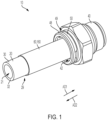
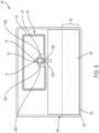
- FIG. 1 is a perspective view of RFID fluid connection 10 .
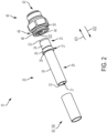
- Figure 2 is an exploded perspective view of RFID fluid connection 10.
- RFID fluid connection 10 generally comprises tube or tube end form or hose 20 , fluid connector 40 , retaining ring 50 , and RFID assembly 60 , 160 . The following description should be read in view of Figures 1-2 .
- Tube end form 20 comprises end 22 , section 23 , shoulder 27 , section 29 , end 32 , and through-bore 21 .
- Through-bore 21 extends through tube end form 20 from end 22 to end 32 .
- Section 23 is arranged between end 22 and shoulder 27 and comprises radially outward facing surface 24 .
- Radially outward facing surface 24 includes a substantially constant diameter.
- Shoulder 27 is arranged between section 23 and section 29 and comprises radially outward facing surface 26 .
- Radially outward facing surface 26 is a linear conical (or frusto-conical) shape and increases in diameter in axial direction AD2 .
- Section 29 is arranged between shoulder 27 and end 32 and comprises radially outward facing surface 30 .
- Radially outward facing surface 30 includes a substantially constant diameter.
- Tube end form 20 is arranged to be inserted, specifically with end 22 first, into fluid connector 40 .
- Tube end form 20 may utilize a straight ramp (i.e., constant linear ramp) or a curvilinear ramp, and is inserted into fluid connector 40 , in axial direction AD1 , until retaining ring 50 snaps over shoulder 27 and is generally aligned with section 29 .
- tube end form 20 may be any traditional tube end form comprising a ramp, which extends radially outward and axially on the outer surface of the tube end form, to displace a retaining ring, snap ring, or wire clip within the fluid connector to secure the tube end form within the fluid connector.
- tube end form 20 comprises any tube end form that might utilize a retaining ring, retaining clip, snap ring etc.
- tube end form 20 may comprise a bead, a notch, a plurality of ramps, threading, a shoulder having a variable diameter portion (ramp) and a constant diameter portion connected thereto, any standard Society of Automotive Engineers (SAE) end form, etc.
- SAE Society of Automotive Engineers
- RFID assembly 60 , 160 verifies that retaining ring 50 has "snapped" over shoulder 27 (and is arranged adjacent and/or proximate to shoulder surface 28 ) in order to determine that RFID fluid connection 10 is properly connected, as will be described in greater detail below.
- Fluid connector 40 comprises through-bore 42 , radially inward facing surface 44 , radially inward facing surface 46 (not shown), and radially outward facing surface 48 .
- Radially outward facing surface 48 comprises groove 49 .
- Retaining ring 50 is arranged in groove 49 .
- Retaining ring 50 comprises protrusions 52A , 52B , and 52C (see Figures 5 and 8 ). Protrusions 52A-C extend radially inward through apertures in groove 49 to engage shoulder 27 , specifically, shoulder surface 28 .
- retaining ring 50 may comprise any number of protrusions (e.g., one or more protrusions) suitable for properly connecting tube end form 20 and fluid connector 40 and contacting the one or more contacts of RFID assembly 60 , 160 to indicate proper connection, as will be described in greater detail below.
- retaining ring 50 has no protrusions.
- retaining ring 50 may comprises a "C" clip which comprises a ring having a small section removed therefrom such that it is capable of radially expanding and snapping back to engage the one or more contacts.
- FIG 3 is a top planar view of RFID assembly 60 , in accordance with some embodiments of the present disclosure.
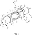
- Figure 4 is a perspective view of RFID assembly 60 arranged on tube end form 20 .
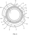
- Figure 5 is a cross-sectional view of RFID assembly 60 arranged on tube end form 20 taken generally along line 5-5 in Figure 4 .
- RFID assembly 60 generally comprises at least one layer (e.g., adhesive layer 62 and/or layer 64 ), RFID tag 70 , and at least one contact (e.g., contact 80A and/or contact 80B ).
- RFID assembly 60 is a RFID label that is connected to a tube or component, wherein the tube or component is arranged to be connected to another component.
- RFID assembly 60 may be used to ensure any type of connection, not just a connection related to the flow of fluid, for example, a constant-velocity (CV) j oint, a trailer hitch connection, electrical connections, etc.
- CV constant-velocity
- Adhesive layer 62 is operatively arranged to be secured to tube end form 20 .
- adhesive layer 62 secures layer 64 and/or contacts 80A and 80B to tube end form 20 .
- layer 64 need not be connected to tube end form 20 via adhesives (i.e., adhesive layer 62 ), but rather can be connected and/or applied using any other suitable means, for example, string, tape, hook and loop fastener, solder, welding, etc.
- adhesive layer 62 is wrapped around section 29 of tube end form 20 and is secured to radially outward facing surface 30 proximate to shoulder 27 .
- adhesive layer 62 completely circumscribes radially outward facing surface 30 and overlaps at its ends (see Figure 5 ).
- adhesive layer 62 completely circumscribes radially outward facing surface 30 and its ends abut against each other (see Figure 8 ).
- adhesive layer 62 does not completely circumscribe radially outward facing surface 30 .
- RFID assembly 60 may further comprise layer 64 .
- Layer 64 is connected to the top surface of adhesive layer 62 and is operatively arranged as a platform or base for RFID tag 70 and contacts 80A-B .
- layer 64 comprises ferrite.
- RFID tag 70 and contacts 80A-B are connected directly to the top surface of adhesive layer 62 , without the need for layer 64 .
- RFID tag 70 and contacts 80A-B are connected directly to radially outward facing surface 30 without the need for adhesive layer 62 or layer 64 .
- RFID assembly 60 further comprises layer 66 . Layer 66 is operatively arranged to cover and protect RFID tag 70 .
- layer 66 completely covers RFID tag 70 and at least partially covers contacts 80A and 80B . However, it is required that at least a portion of contacts 80A and 80B are exposed, for example, exposed portions 82A and 82B , such that they are capable of engaging retaining ring 50 , as will be described in greater detail below.
- RFID tag 70 comprises integrated circuit (IC) or chip 72 and antenna 74 .
- RFID tag 70 comprises a passive RFID tag.
- RFID tag 70 comprises an active RFID tag (and further comprises a power source).
- RFID tag 70 comprises a semi-passive RFID tag.
- RFID tag 70 is preprogrammed such that it transmits information, for example, a unique identification (UID) number, the state of RFID assembly 60 (i.e., open or closed), etc.
- Antenna 74 is connected at a first end to IC 72 at antenna radio-frequency (RF) input LA , and at a second end to IC 72 at antenna RF input LB , via conductors 76A and 76B , respectively.
- RFID tag 70 is further connected to contact 80A and contact 80B .
- conductor 78A connects contact 80A with IC 72 at ground pin GND and conductor 78B connects contact 80B with IC 72 at detector pin DP .
- Contact 80A is separated from contact 80B by gap 84 and gap 86 (see Figure 5 ). In some embodiments, gap 84 is equal to gap 86 . In some embodiments, gap 84 is less than gap 86 . In some embodiments, gap 84 is greater than gap 86 .
- Contacts 80A and 80B are arranged proximate to or abutting against shoulder 27 , specifically shoulder surface 28 . Contacts 80A and 80B are operatively arranged to engage with retaining ring 50 . In some embodiments, contacts 80A and 80B are electrical conductors. When tube end form 20 is properly secured in fluid connector 40 , retaining ring 50 expands along shoulder 27 and then snaps behind shoulder surface 28 thereby locking tube end form 20 within fluid connector 40 .
- protrusions 52A-C engage contacts 80A and 80B .
- protrusion 52C (and protrusion 52B ) is engaged with contact 80B and protrusion 52A is engaged with contact 80A .
- retaining ring 50 comprises an electrical conductive material (e.g., metal). As such, retaining ring 50 completes the circuit between contacts 80A-B and IC 72 and causes RFID tag 70 to become enabled (i.e., RFID tag 70 is capable of being powered by an electromagnetic field generated by an external device (not shown)) or switch to a closed state (from an open state).
- RFID tag 70 Prior to completion of the circuit, namely, electrically connecting contact 80B directly with contact 80A , RFID tag 70 is not enabled (i.e., RFID tag 70 is not capable of being powered by an electromagnetic field generated by the external device) or in some embodiments, it indicates an open status.
- an external device such as a RFID reader will detect that RFID tag 70 is enabled, or in a closed state, thereby indicating that RFID fluid connection 10 is properly connected.
- the RFID reader will identify that RFID tag 70 exists and thus determine that RFID fluid connection 10 is properly connected.
- the RFID reader When the circuit is not completed (i.e., contact 80A is not directly connected to contact 80B ), the RFID reader will not detect an enabled RFID tag 70 thereby indicating that RFID fluid connection 10 is not properly connected. Put in yet another way, when RFID tag 70 is disabled, the RFID reader will not identify that RFID tag 70 exists and thus determine that RFID fluid connection 10 is not properly connected.
- RFID tag 70 is always enabled and can be detected and read by a RFID reader regardless of whether contacts 80A and 80B are connected. In such embodiments, when contacts 80A and 80B are not directly connected, for example via retaining ring 50 , RFID tag 70 is capable of transmitting, to a RFID reader, certain information. Such information may include, but is not limited to, a UID number (e.g., for the RFID tag, the tube end form, etc.), size number, model number, serial number, status of RFID tag 70 (i.e., open or closed), uniform resource locator (URL), station identification (i.e., manufacturing LOT number), date/time stamp, description, etc.
- UID number e.g., for the RFID tag, the tube end form, etc.
- size number e.g., for the RFID tag, the tube end form, etc.
- model number e.g., model number
- serial number e.g., serial number
- status of RFID tag 70 i.e., open or closed
- URL uniform resource locator
- RFID tag 70 will always transmit certain data (e.g., a UID number, a status, etc.) provided it is properly functioning.
- RFID tag 70 is preprogrammed to always transmit at least a UID number and a status (i.e., open or closed), for example, using hexadecimal data or a value. This is important because it allows the user to scan a given RFID tag to determine if it is properly functioning (i.e., if the RFID tag is properly transmitting data then it is properly functioning) as well as to determine its current state (i.e., open or closed).
- RFID tag 70 transmits data indicating a closed status.
- RFID tag 70 indicates a first value (e.g., a first hexadecimal value) for an open state and a second value (e.g., second hexadecimal value) for a closed state, the second value being different from the first value.
- RFID tag 70 may include any programming suitable for indicating that it is properly functioning and a differentiation between an open state and a closed state, and that the present disclosure should not be limited to just the use of the hexadecimal system.
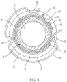
- FIG 6 is a top planar view of RFID assembly 160 , in accordance with some embodiments of the present disclosure.
- Figure 7 is a perspective view of RFID assembly 160 arranged on tube end form 20 .
- Figure 8 is a cross-sectional view of RFID assembly 160 arranged on tube end form 20 taken generally along line 8-8 in Figure 7 .
- RFID assembly 160 generally comprises at least one layer (e.g., adhesive layer 162 and/or layer 164 ), RFID tag 170 , and at least one contact (e.g., contact 180 ).
- RFID assembly 160 is a RFID label that is connected to a tube or component, wherein the tube or component is arranged to be connected to another component.
- RFID assembly 160 may be used to ensure any type of connection, not just a connection related to the flow of fluid, for example, a constant-velocity (CV) joint, a trailer hitch connection, electrical connections, etc.
- CV constant-velocity
- trailer hitch connection electrical connections, etc.
- Adhesive layer 162 is operatively arranged to be secured to tube end form 20 .
- adhesive layer 162 secures layer 164 and/or contact 180 to tube end form 20 .
- layer 164 need not be connected to tube end form 20 via adhesives (i.e., adhesive layer 162 ), but rather can be connected and/or applied using any other suitable means, for example, string, tape, hook and loop fastener, solder, welding, etc.
- adhesive layer 162 is wrapped around section 29 of tube end form 20 and is secured to radially outward facing surface 30 proximate to shoulder 27 .
- adhesive layer 162 completely circumscribes radially outward facing surface 30 and overlaps at its ends (see Figure 5 ).
- adhesive layer 162 completely circumscribes radially outward facing surface 30 and its ends abut against each other (see Figure 8 ).
- adhesive layer 62 does not completely circumscribe radially outward facing surface 30 .
- RFID assembly 160 may further comprise layer 164 .
- Layer 164 is connected to the top surface of adhesive layer 162 and is operatively arranged as a platform or base for RFID tag 170 and contact 180 .
- layer 164 comprises ferrite.
- RFID tag 170 and contact 180 are connected directly to the top surface of adhesive layer 162 , without the need for layer 164 .
- RFID tag 170 and contact 180 are connected directly to radially outward facing surface 30 without the need for adhesive layer 162 or layer 164 .
- RFID assembly 160 further comprises layer 166 .
- Layer 166 is operatively arranged to cover and protect RFID tag 170 .
- layer 166 completely covers RFID tag 170 and at least partially covers contact 180 . However, it is required that at least a portion of contact 180 is exposed, for example exposed portion 182 , such that it is capable of engaging retaining ring 50 , as will be described in greater detail below.
- RFID tag 170 comprises integrated circuit (IC) or chip 172 and antenna 174 .
- RFID tag 170 comprises a passive RFID tag.
- RFID tag 170 comprises an active RFID tag (and further comprises a power source).
- RFID tag 170 comprises a semi-passive RFID tag.
- RFID tag 170 is preprogrammed such that it transmits information, for example, a UID number, the state of RFID assembly 160 (i.e., open or closed), etc.
- Antenna 174 is connected at a first end to IC 172 at antenna radio-frequency (RF) input LA , and at a second end to IC 172 at antenna RF input LB , via conductors 176A and 176B , respectively.
- RFID tag 170 is further connected to contact 180 .
- conductor 178A connects contact 80 with IC 172 at ground pin GND and conductor 178B connects contact 80 with IC 172 at detector pin DP .
- Contact 180 circumscribes radially outward facing surface 30 .
- the ends of contact 180 may be separated by gap 184 .
- the ends of contact 180 abut against each other.
- the ends of contact 180 overlap each other.
- Contact 180 is arranged proximate to or abutting against shoulder 27 , specifically shoulder surface 28 .
- Contact 180 is operatively arranged to engage with retaining ring 50 .
- contact 180 is a pressure sensitive contact.
- retaining ring 50 When retaining ring 50 snaps back behind shoulder 27 and abuts against shoulder surface 28 , protrusions 52A-C engage contact 180 and apply a pressure thereto. For example, and as shown in Figure 8 , protrusions 52A-C are engaged with contact 180 .
- retaining ring 50 comprises metal.
- retaining ring 50 comprises a non-metallic material such as a polymer or an elastomer. It should be appreciated that retaining ring 50 may comprise any material suitable to snap over shoulder 27 and apply pressure to contact 180 .
- the circuit is completed between conductors 178A and 178B and IC 172 and causes RFID tag 170 to become enabled (i.e., RFID tag 170 is capable of being powered by an electromagnetic field generated by an external device (not shown)) or indicate a closed state.
- RFID tag 170 Prior to completion of the circuit, namely, electrically connecting the ends of conductors 178A and 178B , RFID tag 170 is not enabled (i.e., RFID tag 170 is not capable of being powered by an electromagnetic field generated by the external device) or indicates an open state.
- an external device such as a RFID reader will detect that RFID tag 170 is enabled or in a closed state thereby indicating that RFID fluid connection 10 is properly connected. Put another way, when RFID tag 170 is enabled, the RFID reader will identify that RFID tag 170 exists and thus determine that RFID fluid connection 10 is properly connected.
- the RFID reader When the circuit is not completed (i.e., the ends of conductors 178A is not directly connected to contact 178B ), the RFID reader will not detect an enabled RFID tag 170 thereby indicating that RFID fluid connection 10 is not properly connected. Put in yet another way, when RFID tag 170 is disabled, the RFID reader will not identify that RFID tag 170 exists and thus determine that RFID fluid connection 10 is not properly connected.
- RFID tag 170 is always enabled and can be detected and read by a RFID reader regardless of whether conductive layers 190 and 194 are in direct contact. In such embodiments, and as previously discussed, when conductive layers 190 and 194 are not directly connected, for example from the force of retaining ring 50 , RFID tag 170 is capable of transmitting, to a RFID reader, certain information. Such information may include, but is not limited to, a UID number, size number, model number, serial number, status of RFID tag 170 (i.e., open or closed), URL, station identification, date/time stamp, description, etc.
- RFID tag 170 will always transmit data (e.g., a UID number, a status, etc.) provided it is properly functioning.
- RFID tag 170 is preprogrammed to always transmit at least a UID number and a status (i.e., open or closed), for example, using hexadecimal data or a value. This is important because it allows the user to scan a given RFID tag to determine if it is properly functioning (i.e., if the RFID tag is properly transmitting data then it is properly functioning) as well as to determine its current state (i.e., open or closed).
- RFID tag 170 When conductive layers 190 and 194 are connected, for example, by applying a suitable force F to layer 194 via retaining ring 50 , RFID tag 170 transmits data indicating a closed status.
- RFID tag 170 indicates a first value (e.g., a first hexadecimal value) for an open state and a second value (e.g., a second hexadecimal value) for a closed state, the second value being different from the first value.
- RFID tag 170 may include any programming suitable for indicating that it is properly functioning and a differentiation between an open state and a closed state, and that the present disclosure should not be limited to just the use of the hexadecimal system.
- FIG. 9A is a partial cross-sectional schematic view of RFID assembly 160 in an open (or disabled) state, in accordance with some embodiments of the present disclosure. It should be appreciated that this is only one embodiment of a pressure sensitive contact, and that various other pressure sensitive contacts that are known in the art or developed in the future may be used.
- Contact 180 comprises conductive layer 190 , insulating layer 192 , and conductive layer 194 .
- Conductive layer 190 is arranged on the top surface of 164 . In some embodiments, conductive layer 190 is arranged on the top surface of adhesive layer 162 (when layer 164 is not included). In some embodiments, conductive layer 190 is arranged on radially outward facing surface 30 of tube end form 20 (when layers 162 and 164 are not included).
- Insulating layer 192 is arranged on top of layer 190 .
- Conductive layer 194 is arranged on top of insulating layer 192 .
- Insulating layer 192 is operatively arranged to separate conductive layers 190 and 194 until a sufficient force F is applied to conductive layer 194 , as will be described in greater detail below.
- Conductor 178A connects ground pin GND with conductive layer 190 and conductor 178B connects detection pin DP with conductive layer 194 . In some embodiments, conductor 178A connects ground pin GND with conductive layer 194 and conductor 178B connects detection pin DP with conductive layer 190 .
- conductors 178A and 178B remain unconnected and thus RFID tag 170 will indicate an open state or remains disabled (i.e., a RFID reader would not detect that RFID tag 170 exists). As such, in either case, the RFID reader will indicate that RFID fluid connection 10 is not properly secured.
- Figure 9B is a partial cross-sectional schematic view of RFID assembly 160 shown in Figure 9A , in an closed (or enabled) state.
- a sufficient force F is applied to conductive layer 194 , for example via retaining ring 50 , conductive layer 194 is displaced through insulating layer 192 and contacts conductive layer 190 .
- conductors 178A and 178B are electrically connected completing the circuit and RFID tag 170 indicates a closed state or is enabled (i.e., RFID tag 170 is capable of being powered by an electromagnetic field generated by the RFID reader). As such, in either case, the RFID reader will indicate that RFID fluid connection 10 is properly secured.
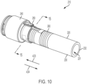
- FIG 10 is a perspective view of RFID fluid connection 210 in a closed (i.e., secured) state.
- Figure 11 is a perspective view of RFID fluid connection 210 in an open (i.e., unsecured) state.
- Figure 12 is an exploded perspective view of RFID fluid connection 210 .
- RFID fluid connection 210 generally comprises tube or hose 220 , fluid connector 240 , retaining ring or clamp 250 , and RFID assembly 260 .
- the following description should be read in view of Figures 10-12 which illustrate an example useful to understand the invention but not an embodiment of it.
- Tube 220 comprises end 222 , end 232 , radially outward facing surface 230 , and through-bore 221 .
- Through-bore 221 extends through tube 220 from end 222 to end 232 .
- Radially outward facing surface 230 includes a substantially constant diameter. In some embodiments, radially outward facing surface 230 varies in diameter.
- tube 220 further comprises a shoulder or a bead connected to radially outward facing surface 230 .
- Tube 220 is arranged to engage fluid connector 240 . Specifically, tube 220 is slid over barb 246 and radially outward facing surface 244 in axial direction AD3 . It should be appreciated that in some embodiments, fluid connector 240 does not comprise barb 246 .
- tube 220 is properly engaged with fluid connector 240 , retaining ring 250 is slid over tube 220 in axial direction AD3 , as shown in Figure 11 .
- retaining ring 250 is crimped to secure tube 220 to fluid connector 240 , as will be described in greater detail below.
- tube 220 comprises rubber or another elastic or flexible material suitable to be securable to a fluid connector via a retainer ring or clamp.
- RFID assembly 260 verifies that retaining ring 250 has adequately tightened around tube 220 and fluid connector 240 in order to determine that RFID fluid connection 210 is properly connected, as will be described in greater detail below.
- Fluid connector 240 comprises through-bore 242 , radially outward facing surface 244 , and barb 246 . Radially outward facing surface 244 and barb 246 are arranged to engage through-bore 221 of tube 220 .
- Retaining ring 250 is arranged to align with radially outward facing surface 244 , as shown in Figures 10-11 .
- Retaining ring 250 comprises radially inward facing surface 252 and crimp section 254 . When crimp section 254 is "crimped" or squeezed, the radius of radially inward facing surface 252 decreases which allows retaining ring 250 to secure tube 220 to fluid connector 240 .
- retaining rings and clamps that may be used are rigid clamps, U-bolt clamps, flat cushion clamps, U-Bolt with cushion clamps, P style clamps, swivel bolt clamps, worm gear hose clamps, OETIKER ® crimp, stepless ear hose clamps, OETIKER ® band clamps, OETIKER ® ear clamps, OETIKER ® STEPLESS ® Ear Clamps PEX Series (e.g., PEXGRIP ® series ear clamps), OETIKER ® spring hose clamps, OETIKER ® snap grip clamps, etc.
- PEX Series e.g., PEXGRIP ® series ear clamps
- OETIKER ® spring hose clamps OETIKER ® snap grip clamps, etc.
- FIG 13 is a top planar view of RFID assembly 260 , in accordance with some embodiments of the present disclosure.
- Figure 14 is a cross-sectional view of RFID fluid connection 210 taken generally along line 14-14 in Figure 11 , in an open state.
- Figure 15 is a cross-section view of RFID fluid connection 210 taken generally along line 15-15 in Figure 10 , in a closed state.
- RFID assembly 260 generally comprises at least one layer (e.g., adhesive layer 262 and/or layer 264 ), RFID tag 270 , and at least one contact (e.g., contact 280A and/or contact 280B ).
- RFID assembly 260 is a RFID label that is connected to a tube or component, wherein the tube or component is arranged to be connected to another component.
- RFID assembly 260 may be used to ensure any type of connection, not just a connection related to the flow of fluid, for example, a constant-velocity (CV) joint, a trailer hitch connection, electrical connections, etc.
- CV constant-velocity
- Adhesive layer 262 is operatively arranged to be secured to tube 220 .
- adhesive layer 262 secures layer 264 and/or contacts 280A and 280B to tube 220 .
- layer 264 need not be connected to tube 220 via adhesives (i.e., adhesive layer 262 ), but rather can be connected and/or applied using any other suitable means, for example, string, tape, hook and loop fastener, solder, welding, etc.
- adhesive layer 262 is wrapped around tube 220 and is secured to radially outward facing surface 230 proximate to end 222 .
- adhesive layer 262 completely circumscribes radially outward facing surface 230 and overlaps at its ends (see Figure 5 ).
- adhesive layer 262 completely circumscribes radially outward facing surface 230 and its ends abut against each other (see Figure 8 ). In some embodiments, adhesive layer 262 does not completely circumscribe radially outward facing surface 230 (see Figures 14-15 ).
- RFID assembly 260 may further comprise layer 264 .
- Layer 264 is connected to the top surface of adhesive layer 262 and is operatively arranged as a platform or base for RFID tag 270 and contacts 280A-B .
- layer 264 comprises ferrite.
- RFID tag 270 and contacts 280A-B are connected directly to the top surface of adhesive layer 262 , without the need for layer 264 .
- RFID tag 270 and contacts 280A-B are connected directly to radially outward facing surface 230 without the need for adhesive layer 262 or layer 264 .
- RFID assembly 260 further comprises layer 266 . Layer 266 is operatively arranged to cover and protect RFID tag 270 .
- layer 266 completely covers RFID tag 270 .
- layer 266 at least partially covers contacts 280A and 280B .
- contacts 280A and 280B are exposed such that they are capable of engaging retaining ring 250 , as will be described in greater detail below.
- RFID tag 270 comprises integrated circuit (IC) or chip 272 and antenna 274 .
- RFID tag 270 comprises a passive RFID tag.
- RFID tag 270 comprises an active RFID tag (and further comprises a power source).
- RFID tag 270 comprises a semi-passive RFID tag.
- RFID tag 270 is preprogrammed such that it transmits information, for example, a unique identification (UID) number, the state of RFID assembly 260 (i.e., open or closed), etc.
- UID unique identification
- Antenna 274 is connected at a first end to IC 272 at antenna radio-frequency (RF) input LA , and at a second end to IC 272 at antenna RF input LB , via conductors 276A and 276B , respectively.
- RFID tag 270 is further connected to contact 280A and contact 280B .
- conductor 278A connects contact 280A with IC 272 at ground pin GND and conductor 278B connects contact 280B with IC 272 at detector pin DP .
- Contact 280A is separated from contact 280B by gap 284 and gap 286 (see Figure 14 ). In some embodiments, gap 284 is equal to gap 286 . In some embodiments, gap 284 is less than gap 286 . In some embodiments, gap 284 is greater than gap 286 .
- Contacts 280A and 280B are arranged proximate to or abutting against end 222 . More specifically, contacts 280A and 280B are operatively arranged to, when RFID fluid connection 210 is properly assembled, align with radially outward facing surface 244 of connector body and retaining ring 250 . Contacts 280A and 280B are operatively arranged to engage with retaining ring 250 .
- contacts 280A and 280B are electrical conductors.
- retaining ring 250 is aligned with radially outward facing surface 244 and contacts 280A and 280B and crimped or squeezed, thereby locking tube 220 onto fluid connector 240 .
- retaining ring 250 is crimped, radially inward facing surface 252 engages contacts 280A and 280B .
- radially inward facing surface 252 of retaining ring 250 is not engaged with either of contacts 280A or 280B , or alternatively, is only engaged with one of contacts 280A and 280B .
- retaining ring 250 comprises an electrically conductive material (e.g., metal). As such, retaining ring 250 completes the circuit between contacts 280A-B and IC 272 and causes RFID tag 270 to switch to a closed state (from an open state). Prior to completion of the circuit, namely, electrically connecting contact 280B directly with contact 280A , RFID tag 270 indicates an open status.
- an external device such as a RFID reader will detect that RFID tag 270 is in a closed state, thereby indicating that RFID fluid connection 210 is properly connected.
- RFID tag 270 is always enabled and can be detected and read by a RFID reader regardless of whether contacts 280A and 280B are connected. In such embodiments, when contacts 280A and 280B are not directly connected, for example via retaining ring 250 , RFID tag 270 is capable of transmitting, to a RFID reader, certain information. Such information may include, but is not limited to, a UID number (e.g., for the RFID tag, the tube end form, etc.), size number, model number, serial number, status of RFID tag 270 (i.e., open or closed), URL, station identification (i.e., manufacturing LOT number), date/time stamp, description, etc.
- UID number e.g., for the RFID tag, the tube end form, etc.
- size number e.g., for the RFID tag, the tube end form, etc.
- model number e.g., model number
- serial number i.e., status of RFID tag 270 (i.e., open or closed)
- URL i.e
- RFID tag 270 will always transmit certain data (e.g., a UID number, a status, etc.) provided it is properly functioning.
- RFID tag 270 is preprogrammed to always transmit at least a UID number and a status (i.e., open or closed), for example, using hexadecimal data or a value. This is important because it allows the user to scan a given RFID tag to determine if it is properly functioning (i.e., if the RFID tag is properly transmitting data then it is properly functioning) as well as to determine its current state (i.e., open or closed).
- RFID tag 270 When contacts 280A and 280B are connected, for example, via retaining ring 250 , RFID tag 270 transmits data indicating a closed status.
- RFID tag 270 indicates a first value (e.g., a first hexadecimal value) for an open state and a second value (e.g., second hexadecimal value) for a closed state, the second value being different from the first value.
- RFID tag 270 may include any programming suitable for indicating that it is properly functioning and a differentiation between an open state and a closed state, and that the present disclosure should not be limited to just the use of the hexadecimal system.
- RFID tags 70 170 , and 270 and RFID assemblies 60 , 160 , and 260 may utilize any suitable radio frequency range.
- RFID tags 70 170 , and 270 comprise low frequency (LF) RFID tags operating in the 30 KHz to 300 KHz range, and have a read range of up to 10 cm. While LF RFID tags have a shorter read range and slower data read rate than other technologies, they perform better in the presence of metal or liquids (which can interfere with other types of RFID tag transmissions). Common standards for LF RFID include ISO 14223 and ISO/IEC 18000-2.
- RFID tags 70 170 , and 270 comprise high frequency (HF) RFID tags operating in the 3 MHz to 30 MHz range and provide reading distances of 10 cm to 1 m.
- RFID tags 70 170 , and 270 may even be near-field communication (NFC) tags since NFC technology is based on HF RFID.
- NFC near-field communication
- Common standards for HF RFID include ISO 15693, ECMA-340, ISO/IEC 18092 (for NFC), ISO/IEC 14443A and ISO/IEC 14443 (for MIFARE and other smart card solutions).
- RFID tags 70 170 , and 270 comprise ultra-high frequency (UHF) RFID operating in the 300 MHz to 2 GHz range and provide reading distances of up to 12 m.
- UHF ultra-high frequency
- a single RFID reader is capable of detecting and receiving data from a plurality of RFID tags, not just one.
Landscapes
- Engineering & Computer Science (AREA)
- General Engineering & Computer Science (AREA)
- Mechanical Engineering (AREA)
- Microelectronics & Electronic Packaging (AREA)
- Theoretical Computer Science (AREA)
- Computer Hardware Design (AREA)
- Physics & Mathematics (AREA)
- General Physics & Mathematics (AREA)
- Computer Networks & Wireless Communication (AREA)
- Details Of Connecting Devices For Male And Female Coupling (AREA)
- Quick-Acting Or Multi-Walled Pipe Joints (AREA)
- Arrangements For Transmission Of Measured Signals (AREA)
- Joints That Cut Off Fluids, And Hose Joints (AREA)
- Flanged Joints, Insulating Joints, And Other Joints (AREA)
- Infusion, Injection, And Reservoir Apparatuses (AREA)
- Rigid Pipes And Flexible Pipes (AREA)
Claims (12)
- Funkfrequenzidentifikations- oder RFID-Fluidverbindung (10), umfassend:eine Fluidverbindungseinrichtung (40) mit einer Durchgangsbohrung (42), mindestens einer radial nach innen weisenden Fläche (44, 46) und einer ersten radial nach außen weisenden Fläche (48), die eine Nut (49) umfasst;eine Röhre (20), die im Betrieb dazu angeordnet ist, in die Fluidverbindungseinrichtung eingefügt und mit dieser verbunden zu werden, wobei die Röhre eine zweite radial nach außen weisende Fläche (30) und eine Schulter (27) aufweist;einen Haltering (50), der im Betrieb dazu angeordnet ist, mit der Fluidverbindungseinrichtung in Eingriff zu kommen, wobei der Haltering in der Nut angeordnet ist und ein oder mehrere Vorsprünge (52A-52C) enthält, die im Betrieb dazu angeordnet sind, durch eine oder mehrere Öffnungen in der Nut zu verlaufen, um mit der Schulter (27) der Röhre in Eingriff zu kommen; undeine RFID-Anordnung (60, 160, 260), die auf der zweiten radial nach außen weisenden Fläche (30) angeordnet ist und die enthält:ein RFID-Tag (70, 170, 270); undmindestens einen Kontakt (80A, 80B, 180, 280A, 280B), der elektrisch mit dem RFID-Tag verbunden ist;wobei der eine oder die mehreren Vorsprünge (52A-52C) des Halterings im Betrieb dazu eingerichtet sind, in Kontakt mit dem mindestens einen Kontakt zu stehen.
- RFID-Fluidverbindung (10) nach Anspruch 1, wobei:die Schulter (27) mit der zweiten radial nach außen weisenden Fläche (30) verbunden ist, wobei die Schulter dazu angeordnet ist, mit dem Haltering (50) zusammenzuwirken, um die Röhre (20) innerhalb des Fluidverbinders (40) zu verriegeln; und,der mindestens eine Kontakt (80A, 80B, 180) im Betrieb nahe an der Schulter dazu angeordnet ist, mit dem Haltering in Eingriff zu kommen.
- RFID-Fluidverbindung (10) nach Anspruch 1, wobei der mindestens eine Kontakt (80A, 80B, 280A, 280B) umfasst:einen ersten Kontakt (80A, 280A), der elektrisch mit dem RFID-Tag (70, 170, 270) verbunden ist; und,einen zweiten Kontakt (80B, 280B), der elektrisch mit dem RFID-Tag verbunden ist, wobei der zweite Kontakt vom ersten Kontakt getrennt ist, um einen offenen Zustand der RFID-Anordnung (60, 160, 260) zu bilden.
- RFID-Fluidverbindung (10) nach Anspruch 3, wobei, wenn die Röhre (20) ordnungsgemäß an der Fluidverbindungseinrichtung (40) befestigt ist:der Haltering (50) mit dem ersten Kontakt (80A, 280A) und dem zweiten Kontakt (80B, 280B) in Eingriff ist; und,der erste Kontakt elektrisch mit dem zweiten Kontakt verbunden ist, um einen geschlossenen Zustand der RFID-Anordnung (60, 160, 260) zu bilden.
- RFID-Fluidverbindung (10) nach Anspruch 1, wobei der Haltering (250) eine Klammer ist.
- RFID-Fluidverbindung (10) nach Anspruch 1, wobei die RFID-Anordnung (60, 160, 260) auf einer Schicht (64, 164, 264) angeordnet ist und die Schicht mit der zweiten radial nach außen weisenden Fläche (30, 230) verbunden ist.
- RFID-Fluidverbindung (10) nach Anspruch 1, wobei:der RFID-Tag (70, 170, 270) eine Antennenschaltung (74, 174, 274) umfasst;die Antennenschaltung in einem offenen Zustand des RFID-Tags offen ist; und,die Antennenschaltung in einem geschlossenen Zustand des RFID-Tags geschlossen ist.
- RFID-Fluidverbindung (10) nach Anspruch 1, wobei:die RFID-Anordnung (60, 160, 260) ferner eine Antenne (74, 174, 274) und eine integrierte Schaltung (72, 172, 272) enthält, wobei der mindestens eine Kontakt (80A, 80B, 180, 280A, 280B) elektrisch mit der integrierten Schaltung verbunden ist;der RFID-Tag, wenn der integrierte Schaltkreis offen ist, eine nicht ordnungsgemäße Verbindung der RFID-Fluidverbindung anzeigt; und,der RFID-Tag, wenn der integrierte Schaltkreis geschlossen ist, eine ordnungsgemäße Verbindung der RFID-Fluidverbindung anzeigt.
- RFID-Fluidverbindung (10) nach Anspruch 1, wobei die RFID-Anordnung (60, 160, 260) auf einer ersten Schicht (62, 64) angeordnet ist und die erste Schicht mit der zweiten radial nach außen weisenden Fläche (30) verbunden ist.
- RFID-Fluidverbindung (10) nach Anspruch 3, wobei in einem geschlossenen Zustand der erste Kontakt (80A, 280A) elektrisch mit dem zweiten Kontakt (80B, 280B) verbunden ist.
- RFID-Fluidverbindung (10) nach Anspruch 1, wobei der mindestens eine Kontakt (80A, 80B, 180, 280A, 280B) einen druckempfindlichen Kontakt (180) umfasst, der über eine erste Leitung (178B) und eine zweite Leitung (178A) elektrisch mit dem RFID-Tag (170) verbunden ist.
- RFID-Fluidverbindung (10) nach Anspruch 11, wobei der druckempfindliche Kontakt (180) umfasst:eine erste leitende Schicht (194), die elektrisch mit der ersten Leitung (178B) verbunden ist;eine zweite leitende Schicht (190), die elektrisch mit der zweiten Leitung (178A) verbunden ist; undeine Isolierschicht (192), die die erste leitende Schicht und die zweite leitende Schicht trennt, um einen offenen Zustand der RFID-Anordnung (160) zu bilden.
Priority Applications (1)
| Application Number | Priority Date | Filing Date | Title |
|---|---|---|---|
| EP24193370.4A EP4435311A3 (de) | 2019-09-30 | 2020-06-15 | Hochfrequenz-identifikationsverbindung |
Applications Claiming Priority (2)
| Application Number | Priority Date | Filing Date | Title |
|---|---|---|---|
| US201962907758P | 2019-09-30 | 2019-09-30 | |
| PCT/US2020/037736 WO2021066895A1 (en) | 2019-09-30 | 2020-06-15 | Radio-frequency identification connection |
Related Child Applications (2)
| Application Number | Title | Priority Date | Filing Date |
|---|---|---|---|
| EP24193370.4A Division-Into EP4435311A3 (de) | 2019-09-30 | 2020-06-15 | Hochfrequenz-identifikationsverbindung |
| EP24193370.4A Division EP4435311A3 (de) | 2019-09-30 | 2020-06-15 | Hochfrequenz-identifikationsverbindung |
Publications (3)
| Publication Number | Publication Date |
|---|---|
| EP4038302A1 EP4038302A1 (de) | 2022-08-10 |
| EP4038302C0 EP4038302C0 (de) | 2024-10-30 |
| EP4038302B1 true EP4038302B1 (de) | 2024-10-30 |
Family
ID=71409557
Family Applications (3)
| Application Number | Title | Priority Date | Filing Date |
|---|---|---|---|
| EP20735790.6A Active EP4038302B1 (de) | 2019-09-30 | 2020-06-15 | Hochfrequenz-identifikationsverbindung |
| EP24193370.4A Pending EP4435311A3 (de) | 2019-09-30 | 2020-06-15 | Hochfrequenz-identifikationsverbindung |
| EP20735792.2A Active EP4038300B1 (de) | 2019-09-30 | 2020-06-15 | Hochfrequenz-identifikationsverbinder |
Family Applications After (2)
| Application Number | Title | Priority Date | Filing Date |
|---|---|---|---|
| EP24193370.4A Pending EP4435311A3 (de) | 2019-09-30 | 2020-06-15 | Hochfrequenz-identifikationsverbindung |
| EP20735792.2A Active EP4038300B1 (de) | 2019-09-30 | 2020-06-15 | Hochfrequenz-identifikationsverbinder |
Country Status (10)
| Country | Link |
|---|---|
| US (4) | US11913573B2 (de) |
| EP (3) | EP4038302B1 (de) |
| JP (2) | JP7447250B2 (de) |
| KR (2) | KR102722217B1 (de) |
| CN (2) | CN114502865B (de) |
| CA (2) | CA3147975C (de) |
| ES (1) | ES2999933T3 (de) |
| MX (3) | MX2022002830A (de) |
| PL (1) | PL4038302T3 (de) |
| WO (2) | WO2021066896A1 (de) |
Families Citing this family (5)
| Publication number | Priority date | Publication date | Assignee | Title |
|---|---|---|---|---|
| CN114502865B (zh) * | 2019-09-30 | 2024-12-17 | 欧梯克纽约股份有限公司 | 射频识别连接器 |
| CA3154823A1 (en) * | 2019-11-01 | 2021-05-06 | Thomas A. Puvogel | Fluid line connector and assembly with securement detection |
| US12007053B2 (en) * | 2020-03-12 | 2024-06-11 | Ti Group Automotive Systems, Llc | Transmitter for quick connector |
| DE102023133217A1 (de) * | 2022-12-06 | 2024-06-06 | Illinois Tool Works Inc. | Fluidkopplungsvorrichtung sowie Verfahren zum Koppeln von zwei Fluidleitungen |
| DE102023111635A1 (de) * | 2023-05-04 | 2024-11-07 | Bayerische Motoren Werke Aktiengesellschaft | Befestigungsvorrichtung mit überprüfbarer Montageposition |
Family Cites Families (45)
| Publication number | Priority date | Publication date | Assignee | Title |
|---|---|---|---|---|
| US2941823A (en) | 1954-12-21 | 1960-06-21 | North American Aviation Inc | W-band coupling for flanged pipe |
| JPS62292495A (ja) * | 1986-06-11 | 1987-12-19 | 株式会社東芝 | Icカ−ドおよびその発行方法、ならびにこれに用いる導通スイツチ |
| JP3217688B2 (ja) | 1996-03-14 | 2001-10-09 | 株式会社東芝 | スペクトラム拡散受信機の同期追跡装置 |
| ES2351549T3 (es) * | 2000-03-21 | 2011-02-07 | Mikoh Corporation | Una etiqueta de identificación por radiofrecuencia con indicación de manipulación indebida. |
| JP4264325B2 (ja) | 2003-08-07 | 2009-05-13 | 株式会社パイオラックス | 接続構造或いは締結構造 |
| US7244142B2 (en) * | 2003-08-07 | 2007-07-17 | Piolax Inc. | Connection structure or fastening structure with resonant circuit |
| DE202004002116U1 (de) | 2004-02-11 | 2004-06-24 | Faller Jun., Alexander | Prüfbare Verbindung |
| JP2005315653A (ja) * | 2004-04-27 | 2005-11-10 | Nippon Signal Co Ltd:The | 実装状態検査装置 |
| US7394375B2 (en) * | 2004-09-24 | 2008-07-01 | Colder Products Company | Coupler with radio frequency identification tag |
| JP2006349461A (ja) * | 2005-06-15 | 2006-12-28 | Sharp Corp | Rfid型触覚センサ及びrfid型触覚センサ入力装置 |
| CN101228670B (zh) * | 2005-07-25 | 2010-05-12 | Fci公司 | 具有配合状态指示部件的电连接装置 |
| FR2891888B1 (fr) | 2005-10-10 | 2008-04-04 | Comap Sa | Raccord a sertir pour tube |
| US8328458B2 (en) * | 2007-07-20 | 2012-12-11 | Twin Bay Medical, Inc. | Sanitary clamp |
| US7855697B2 (en) * | 2007-08-13 | 2010-12-21 | Corning Cable Systems, Llc | Antenna systems for passive RFID tags |
| WO2010132572A1 (en) | 2009-05-12 | 2010-11-18 | Band-It-Idex, Inc. | Band clamp with embedded electronics |
| EP2333691B1 (de) | 2009-12-14 | 2013-04-10 | KTS Kommunikationstechnik und Systeme GmbH | Verbindungskabel zur elektrischen oder Lichtwellenleiterverbindung zweier Systemgeräte |
| CN201810616U (zh) * | 2010-08-05 | 2011-04-27 | 江苏凯路威电子有限公司 | 一种射频识别抱箍 |
| EP2463809A1 (de) * | 2010-12-07 | 2012-06-13 | NagraID S.A. | Elektronische Karte mit elektrischem Kontakt, die eine elektronische Einheit und/oder eine Antenne umfasst |
| EP2689798B1 (de) * | 2011-03-24 | 2015-10-28 | Terumo Kabushiki Kaisha | Verbinderanordnung, stecker und buchse |
| JP5348709B2 (ja) * | 2011-12-22 | 2013-11-20 | Necインフロンティア株式会社 | 非接触icカードおよび非接触icカードスキミング防止方法 |
| US8746041B2 (en) | 2012-01-18 | 2014-06-10 | Joseph J. Howard | Systems and methods for detecting and communicating moisture leaks in fluid conduits |
| NO336176B1 (no) | 2012-08-24 | 2015-06-01 | Depro As | Rørklemme forsynt med forspenningsavleser og bruk av forspenningsavleser på en rørklemme |
| FR3007815B1 (fr) * | 2013-06-28 | 2016-04-29 | Sartorius Stedim Biotech | Connecteur fluidique avec verrouillage. |
| JP6231358B2 (ja) | 2013-11-11 | 2017-11-15 | 株式会社日立システムズ | Rfidタグ組込リング |
| US20160131328A1 (en) * | 2014-11-07 | 2016-05-12 | Lighthouse Technologies Limited | Indoor smd led equipped for outdoor usage |
| US10563806B2 (en) | 2015-02-06 | 2020-02-18 | Ruben Adolfo MENCOS | Electrofusion pipe fittings, methods, and systems |
| CN204360938U (zh) * | 2015-02-16 | 2015-05-27 | 杨喜财 | 自动门开关 |
| US10584813B2 (en) | 2015-09-10 | 2020-03-10 | Entegris, Inc. | Anti-rotation device for hydraulic connectors |
| CN204927088U (zh) * | 2015-09-16 | 2015-12-30 | 海宁大源电子有限公司 | 坐垫压力开关 |
| EP3353456B1 (de) * | 2015-09-24 | 2020-12-23 | Lenlok Holdings, LLC | Rohrverbindung mit sensor |
| JP6561858B2 (ja) * | 2016-01-25 | 2019-08-21 | 株式会社村田製作所 | ジャケット型デバイス及びジャケット型デバイス付き携帯通信端末 |
| EP3249634B1 (de) | 2016-05-26 | 2024-05-15 | Nxp B.V. | Manipulationsdetektionsvorrichtung |
| US9667000B1 (en) * | 2016-06-09 | 2017-05-30 | Delphi Technologies, Inc. | Radio frequency coaxial connector assembly and method of manufacturing same |
| CN105910529A (zh) * | 2016-06-24 | 2016-08-31 | 深圳市步莱恩科技有限公司 | 一种电阻式位移传感器 |
| WO2018089731A1 (en) * | 2016-11-11 | 2018-05-17 | The Cleveland Clinic Foundation | Rapid-exchange system and method |
| CN206478357U (zh) * | 2016-11-23 | 2017-09-08 | 黄松檀 | 一种应用于智能汽车的管路连接器 |
| US10690277B2 (en) * | 2017-03-16 | 2020-06-23 | Oetiker Ny, Inc. | Radio frequency identification smart inspection assurance cap |
| US11199282B2 (en) | 2017-08-11 | 2021-12-14 | Norma U.S. Holding Llc | Fluid line connector and assembly with securement detection |
| KR102382556B1 (ko) | 2017-08-11 | 2022-04-04 | 노마 유.에스. 홀딩 엘엘씨 | 고정 감지 기능이 있는 유체 라인 커넥터 및 조립체 |
| US20190050210A1 (en) * | 2017-08-11 | 2019-02-14 | Fugue, Inc. | System and method for providing cloud operating system verifications for a domain-specific language for cloud services infrastructure |
| RU2739511C1 (ru) * | 2017-08-14 | 2020-12-25 | Отикер Нй, Инк. | Быстроразъемное соединение с индикаторным выступом |
| KR20190054320A (ko) * | 2017-11-13 | 2019-05-22 | (주)고려기업 | 와이어 로프 슬링 |
| US11263504B2 (en) * | 2018-02-01 | 2022-03-01 | Shockwatch, Inc. | Temperature indicator |
| EP3544114B1 (de) * | 2018-03-20 | 2023-05-03 | A. Raymond et CIE-SCS | Resonanz-hochfrequenz-verbindungsverifizierungssystem |
| CN114502865B (zh) * | 2019-09-30 | 2024-12-17 | 欧梯克纽约股份有限公司 | 射频识别连接器 |
-
2020
- 2020-06-15 CN CN202080068446.1A patent/CN114502865B/zh active Active
- 2020-06-15 EP EP20735790.6A patent/EP4038302B1/de active Active
- 2020-06-15 KR KR1020227014055A patent/KR102722217B1/ko active Active
- 2020-06-15 MX MX2022002830A patent/MX2022002830A/es unknown
- 2020-06-15 EP EP24193370.4A patent/EP4435311A3/de active Pending
- 2020-06-15 CA CA3147975A patent/CA3147975C/en active Active
- 2020-06-15 KR KR1020227013990A patent/KR102703621B1/ko active Active
- 2020-06-15 JP JP2022519975A patent/JP7447250B2/ja active Active
- 2020-06-15 MX MX2022003021A patent/MX2022003021A/es unknown
- 2020-06-15 WO PCT/US2020/037760 patent/WO2021066896A1/en not_active Ceased
- 2020-06-15 US US17/635,237 patent/US11913573B2/en active Active
- 2020-06-15 PL PL20735790.6T patent/PL4038302T3/pl unknown
- 2020-06-15 EP EP20735792.2A patent/EP4038300B1/de active Active
- 2020-06-15 CN CN202080065308.8A patent/CN114424201B/zh active Active
- 2020-06-15 US US17/635,249 patent/US11933433B2/en active Active
- 2020-06-15 JP JP2022519976A patent/JP7457107B2/ja active Active
- 2020-06-15 ES ES20735790T patent/ES2999933T3/es active Active
- 2020-06-15 WO PCT/US2020/037736 patent/WO2021066895A1/en not_active Ceased
- 2020-06-15 CA CA3149440A patent/CA3149440A1/en active Pending
-
2022
- 2022-03-08 MX MX2026000052A patent/MX2026000052A/es unknown
-
2024
- 2024-02-12 US US18/439,078 patent/US12292140B2/en active Active
-
2025
- 2025-04-01 US US19/096,864 patent/US20250230884A1/en active Pending
Also Published As
Similar Documents
| Publication | Publication Date | Title |
|---|---|---|
| EP4038302B1 (de) | Hochfrequenz-identifikationsverbindung | |
| US10690277B2 (en) | Radio frequency identification smart inspection assurance cap | |
| US6738025B2 (en) | Antenna matching circuit | |
| US20220010907A1 (en) | Transmitter for quick connector | |
| CA2400693A1 (en) | Power source system for rf location/identification tags | |
| US20120126945A1 (en) | Strong passive ad-hoc rado-frequency identification | |
| WO2004095353A3 (fr) | Procede et dispositif de detection et d’identification d’objets, conteneurs securises et systemes pourvus de ce dispositif et objets adaptes pour ce procede | |
| US7136683B2 (en) | Surface acoustic wave sensor and radio frequency identification interrogator fixture | |
| US11808392B2 (en) | Connection verifier | |
| AU2002247240A1 (en) | Antenna matching circuit |
Legal Events
| Date | Code | Title | Description |
|---|---|---|---|
| STAA | Information on the status of an ep patent application or granted ep patent |
Free format text: STATUS: UNKNOWN |
|
| STAA | Information on the status of an ep patent application or granted ep patent |
Free format text: STATUS: THE INTERNATIONAL PUBLICATION HAS BEEN MADE |
|
| PUAI | Public reference made under article 153(3) epc to a published international application that has entered the european phase |
Free format text: ORIGINAL CODE: 0009012 |
|
| STAA | Information on the status of an ep patent application or granted ep patent |
Free format text: STATUS: REQUEST FOR EXAMINATION WAS MADE |
|
| 17P | Request for examination filed |
Effective date: 20220221 |
|
| AK | Designated contracting states |
Kind code of ref document: A1 Designated state(s): AL AT BE BG CH CY CZ DE DK EE ES FI FR GB GR HR HU IE IS IT LI LT LU LV MC MK MT NL NO PL PT RO RS SE SI SK SM TR |
|
| DAV | Request for validation of the european patent (deleted) | ||
| DAX | Request for extension of the european patent (deleted) | ||
| STAA | Information on the status of an ep patent application or granted ep patent |
Free format text: STATUS: EXAMINATION IS IN PROGRESS |
|
| 17Q | First examination report despatched |
Effective date: 20240117 |
|
| GRAP | Despatch of communication of intention to grant a patent |
Free format text: ORIGINAL CODE: EPIDOSNIGR1 |
|
| STAA | Information on the status of an ep patent application or granted ep patent |
Free format text: STATUS: GRANT OF PATENT IS INTENDED |
|
| INTG | Intention to grant announced |
Effective date: 20240705 |
|
| GRAS | Grant fee paid |
Free format text: ORIGINAL CODE: EPIDOSNIGR3 |
|
| GRAA | (expected) grant |
Free format text: ORIGINAL CODE: 0009210 |
|
| STAA | Information on the status of an ep patent application or granted ep patent |
Free format text: STATUS: THE PATENT HAS BEEN GRANTED |
|
| AK | Designated contracting states |
Kind code of ref document: B1 Designated state(s): AL AT BE BG CH CY CZ DE DK EE ES FI FR GB GR HR HU IE IS IT LI LT LU LV MC MK MT NL NO PL PT RO RS SE SI SK SM TR |
|
| REG | Reference to a national code |
Ref country code: GB Ref legal event code: FG4D |
|
| REG | Reference to a national code |
Ref country code: CH Ref legal event code: EP |
|
| REG | Reference to a national code |
Ref country code: DE Ref legal event code: R096 Ref document number: 602020040301 Country of ref document: DE |
|
| REG | Reference to a national code |
Ref country code: IE Ref legal event code: FG4D |
|
| U01 | Request for unitary effect filed |
Effective date: 20241113 |
|
| U07 | Unitary effect registered |
Designated state(s): AT BE BG DE DK EE FI FR IT LT LU LV MT NL PT RO SE SI Effective date: 20241120 |
|
| REG | Reference to a national code |
Ref country code: ES Ref legal event code: FG2A Ref document number: 2999933 Country of ref document: ES Kind code of ref document: T3 Effective date: 20250227 |
|
| PG25 | Lapsed in a contracting state [announced via postgrant information from national office to epo] |
Ref country code: IS Free format text: LAPSE BECAUSE OF FAILURE TO SUBMIT A TRANSLATION OF THE DESCRIPTION OR TO PAY THE FEE WITHIN THE PRESCRIBED TIME-LIMIT Effective date: 20250228 Ref country code: HR Free format text: LAPSE BECAUSE OF FAILURE TO SUBMIT A TRANSLATION OF THE DESCRIPTION OR TO PAY THE FEE WITHIN THE PRESCRIBED TIME-LIMIT Effective date: 20241030 |
|
| PG25 | Lapsed in a contracting state [announced via postgrant information from national office to epo] |
Ref country code: NO Free format text: LAPSE BECAUSE OF FAILURE TO SUBMIT A TRANSLATION OF THE DESCRIPTION OR TO PAY THE FEE WITHIN THE PRESCRIBED TIME-LIMIT Effective date: 20250130 |
|
| PG25 | Lapsed in a contracting state [announced via postgrant information from national office to epo] |
Ref country code: GR Free format text: LAPSE BECAUSE OF FAILURE TO SUBMIT A TRANSLATION OF THE DESCRIPTION OR TO PAY THE FEE WITHIN THE PRESCRIBED TIME-LIMIT Effective date: 20250131 |
|
| PG25 | Lapsed in a contracting state [announced via postgrant information from national office to epo] |
Ref country code: RS Free format text: LAPSE BECAUSE OF FAILURE TO SUBMIT A TRANSLATION OF THE DESCRIPTION OR TO PAY THE FEE WITHIN THE PRESCRIBED TIME-LIMIT Effective date: 20250130 |
|
| PG25 | Lapsed in a contracting state [announced via postgrant information from national office to epo] |
Ref country code: SM Free format text: LAPSE BECAUSE OF FAILURE TO SUBMIT A TRANSLATION OF THE DESCRIPTION OR TO PAY THE FEE WITHIN THE PRESCRIBED TIME-LIMIT Effective date: 20241030 |
|
| PGFP | Annual fee paid to national office [announced via postgrant information from national office to epo] |
Ref country code: PL Payment date: 20250603 Year of fee payment: 6 |
|
| PGFP | Annual fee paid to national office [announced via postgrant information from national office to epo] |
Ref country code: GB Payment date: 20250617 Year of fee payment: 6 |
|
| PG25 | Lapsed in a contracting state [announced via postgrant information from national office to epo] |
Ref country code: SK Free format text: LAPSE BECAUSE OF FAILURE TO SUBMIT A TRANSLATION OF THE DESCRIPTION OR TO PAY THE FEE WITHIN THE PRESCRIBED TIME-LIMIT Effective date: 20241030 |
|
| PGFP | Annual fee paid to national office [announced via postgrant information from national office to epo] |
Ref country code: TR Payment date: 20250529 Year of fee payment: 6 |
|
| PG25 | Lapsed in a contracting state [announced via postgrant information from national office to epo] |
Ref country code: CZ Free format text: LAPSE BECAUSE OF FAILURE TO SUBMIT A TRANSLATION OF THE DESCRIPTION OR TO PAY THE FEE WITHIN THE PRESCRIBED TIME-LIMIT Effective date: 20241030 |
|
| U20 | Renewal fee for the european patent with unitary effect paid |
Year of fee payment: 6 Effective date: 20250630 |
|
| PLBE | No opposition filed within time limit |
Free format text: ORIGINAL CODE: 0009261 |
|
| STAA | Information on the status of an ep patent application or granted ep patent |
Free format text: STATUS: NO OPPOSITION FILED WITHIN TIME LIMIT |
|
| 26N | No opposition filed |
Effective date: 20250731 |
|
| PGFP | Annual fee paid to national office [announced via postgrant information from national office to epo] |
Ref country code: ES Payment date: 20250710 Year of fee payment: 6 |
|
| PGFP | Annual fee paid to national office [announced via postgrant information from national office to epo] |
Ref country code: CH Payment date: 20250701 Year of fee payment: 6 |
|
| PG25 | Lapsed in a contracting state [announced via postgrant information from national office to epo] |
Ref country code: MC Free format text: LAPSE BECAUSE OF FAILURE TO SUBMIT A TRANSLATION OF THE DESCRIPTION OR TO PAY THE FEE WITHIN THE PRESCRIBED TIME-LIMIT Effective date: 20241030 |
|
| PG25 | Lapsed in a contracting state [announced via postgrant information from national office to epo] |
Ref country code: IE Free format text: LAPSE BECAUSE OF NON-PAYMENT OF DUE FEES Effective date: 20250615 |