EP4038420B1 - Datengesteuertes verfahren zur invertierung für die bildung von anisotropen konstanten unter verwendung von bohrloch-schalldaten - Google Patents
Datengesteuertes verfahren zur invertierung für die bildung von anisotropen konstanten unter verwendung von bohrloch-schalldaten Download PDFInfo
- Publication number
- EP4038420B1 EP4038420B1 EP20872125.8A EP20872125A EP4038420B1 EP 4038420 B1 EP4038420 B1 EP 4038420B1 EP 20872125 A EP20872125 A EP 20872125A EP 4038420 B1 EP4038420 B1 EP 4038420B1
- Authority
- EP
- European Patent Office
- Prior art keywords
- dispersions
- mismatch
- theoretical
- dispersion
- waveform
- Prior art date
- Legal status (The legal status is an assumption and is not a legal conclusion. Google has not performed a legal analysis and makes no representation as to the accuracy of the status listed.)
- Active
Links
Images







Classifications
-
- G—PHYSICS
- G01—MEASURING; TESTING
- G01V—GEOPHYSICS; GRAVITATIONAL MEASUREMENTS; DETECTING MASSES OR OBJECTS; TAGS
- G01V1/00—Seismology; Seismic or acoustic prospecting or detecting
- G01V1/28—Processing seismic data, e.g. for interpretation or for event detection
- G01V1/30—Analysis
- G01V1/306—Analysis for determining physical properties of the subsurface, e.g. impedance, porosity or attenuation profiles
-
- G—PHYSICS
- G01—MEASURING; TESTING
- G01V—GEOPHYSICS; GRAVITATIONAL MEASUREMENTS; DETECTING MASSES OR OBJECTS; TAGS
- G01V1/00—Seismology; Seismic or acoustic prospecting or detecting
- G01V1/28—Processing seismic data, e.g. for interpretation or for event detection
- G01V1/282—Application of seismic models, synthetic seismograms
-
- G—PHYSICS
- G01—MEASURING; TESTING
- G01V—GEOPHYSICS; GRAVITATIONAL MEASUREMENTS; DETECTING MASSES OR OBJECTS; TAGS
- G01V1/00—Seismology; Seismic or acoustic prospecting or detecting
- G01V1/40—Seismology; Seismic or acoustic prospecting or detecting specially adapted for well-logging
- G01V1/44—Seismology; Seismic or acoustic prospecting or detecting specially adapted for well-logging using generators and receivers in the same well
- G01V1/48—Processing data
- G01V1/50—Analysing data
-
- G—PHYSICS
- G01—MEASURING; TESTING
- G01V—GEOPHYSICS; GRAVITATIONAL MEASUREMENTS; DETECTING MASSES OR OBJECTS; TAGS
- G01V2210/00—Details of seismic processing or analysis
- G01V2210/50—Corrections or adjustments related to wave propagation
- G01V2210/58—Media-related
- G01V2210/582—Dispersion
-
- G—PHYSICS
- G01—MEASURING; TESTING
- G01V—GEOPHYSICS; GRAVITATIONAL MEASUREMENTS; DETECTING MASSES OR OBJECTS; TAGS
- G01V2210/00—Details of seismic processing or analysis
- G01V2210/60—Analysis
- G01V2210/61—Analysis by combining or comparing a seismic data set with other data
- G01V2210/614—Synthetically generated data
-
- G—PHYSICS
- G01—MEASURING; TESTING
- G01V—GEOPHYSICS; GRAVITATIONAL MEASUREMENTS; DETECTING MASSES OR OBJECTS; TAGS
- G01V2210/00—Details of seismic processing or analysis
- G01V2210/60—Analysis
- G01V2210/62—Physical property of subsurface
- G01V2210/622—Velocity, density or impedance
- G01V2210/6222—Velocity; travel time
-
- G—PHYSICS
- G01—MEASURING; TESTING
- G01V—GEOPHYSICS; GRAVITATIONAL MEASUREMENTS; DETECTING MASSES OR OBJECTS; TAGS
- G01V2210/00—Details of seismic processing or analysis
- G01V2210/60—Analysis
- G01V2210/62—Physical property of subsurface
- G01V2210/626—Physical property of subsurface with anisotropy
Definitions
- aspects of the disclosure relate to manipulation of sonic data. More specifically, aspects of the disclosure relate to methods for inversion of formation anisotropic constants using sonic data.
- sonic waveform processing workflow mainly consists of the evaluation of formation compressional (dtc) and shear (dts) slownesses, or P&S. These two logs can be extracted by waveforms from a monopole or a dipole transmitter or a quadrupole transmitter using Schlumberger Technology Corporation equipment. Most sedimentary rock, however, exhibits a certain degree of anisotropy. This is particularly true for geological deposits that incorporate shale. This anisotropy effect plays an important role in geomechanical studies. The most commonly observed anisotropy type in shale is called vertical transverse isotropy (VTI), where five parameters are required to describe elastic constants.
- VTI vertical transverse isotropy
- this type of anisotropy can be described by two vertical slowness (i.e., dtc and dts, or alternatively by two velocities, i.e., V P 0 and Vs0) and three dimensionless (so called "Thomsen”) parameters ⁇ , ⁇ , and ⁇ , that reduce to zeros for an isotropic formation.
- These three parameters are required to build the mechanical earth model (MEM) for geomechanical analysis, such as estimation of rock stiffness, strength, stresses, sanding prediction, wellbore stability and hydraulic fracturing design.
- MEM mechanical earth model
- the three Thomsen parameters described above cannot directly be measured by a borehole sonic logging tool along a single orientation at a given depth.
- Model-based inversion methods are used to estimate these anisotropy constants.
- Such model-based inversion methods are not robust and may yield unreliable results because of the existence of several local minimum in the cost function, which is defined by the mismatch between the measured borehole modes and the theoretical borehole modes.
- mud properties in the downhole environment are also required to be known so that the model-based inversion can be calculated. These mud properties, however, are often not measured. In some cases, these mud property values may have a large influence on the borehole dispersion modes.
- WO2017/172371 A1 describes a method for verifying measurements of elastic anisotropic parameters in a wellbore.
- a portion of an anisotropy formation through which a wellbore is formed is identified and an estimate of an elastic anisotropy parameter for the portion is adjusted based on a first quality control analysis using the elastic anisotropy parameter for the portion.
- the estimate of the elastic anisotropy parameter for the portion can be adjusted based on a second quality control analysis using estimates for the elastic anisotropy parameters for two or more portions of the anisotropy formation.
- the present invention resides in a method as defined in claim 1.
- first, second, third, etc. may be used herein to describe various elements, components, regions, layers and/or sections, these elements, components, regions, layers and/or sections should not be limited by these terms. These terms may be only used to distinguish one element, component, region, layer or section from another region, layer or section. Terms such as “first”, “second” and other numerical terms, when used herein, do not imply a sequence or order unless clearly indicated by the context. Thus, a first element, component, region, layer or section discussed herein could be termed a second element, component, region, layer or section without departing from the teachings of the example embodiments.
- aspects described apply to the field of borehole sonic waveform processing.
- Application of methods described can provide quantification on magnitudes and uncertainties of anisotropic elastic constants (e.g., the three Thomsen parameters in a vertical transversely isotropic (VTI) formation) along with borehole mud slownesses as a function of depth.
- the methods described can be used with a sonic logging tool equipped with a single mode transmitter or multiple mode transmitters.
- Embodiments presented are applicable to both wireline and logging-while-drilling tools.
- the obtained anisotropic elastic constants can then be used in petrophysical and geomechanical applications.
- the objective of aspects of the disclosure is to deliver the estimation of the anisotropic parameters (e.g., the three Thomsen parameters) along with borehole mud slownesses as a function of depth, using a physically-constrained data-driven approach.
- the whole workflow/method may include three steps. First, a comprehensive random or grid searching algorithm is performed to match all possible theoretical borehole dispersion curves to the measured borehole modes of a sonic logging tool. The search range is constrained based on certain initial physical or empirical correlations. The first step can give rough estimates of the mud slowness as either linear profile, multi-linear profile, or non-linear profile over depth.
- the same dispersion match process is repeated using the linear, multi-linear or non-linear profiles of mud slowness obtained from the 1 st step.
- the second step may give estimation of anisotropic parameters (e.g., Thomsen parameters). Because anisotropic parameters are often observed to follow certain strong correlations for a given formation, a linear regression or non-linear regression method can be applied to obtain a local correlation model using the inversion results in the 2nd step.
- the search process is repeated to match the measured borehole mode dispersions, whereas the newly constrained correlations are applied in defining the search range of anisotropic parameters and thereby can get a more reliable estimate of the anisotropic parameters.
- Table 1 Laboratory measured linear elastic constants of rock samples from [3] [4] and [5] Rock samples ⁇ g/cm 3 c 11 GPa c 33 GPa c 44 GPa c 13 GPa c 66 GPa ⁇ ⁇ ⁇ Africa shale D1 2.41 30.62 24.64 6.19 13.37 7.89 0.121 0.138 0.046 Africa shale E1 2.51 39.90 24.41 5.89 11.25 11.93 0.317 0.513 -0.054 Africa shale E3 2.50 38.87 26.80 6.85 17.00 12.55 0.225 0.416 0.160 Africa shale E4 2.57 49.22 35.95 10.80 13.25 15.96 0.185 0.239 -0.030 Africa shale E5 2.54 43.50 26.33 6.54 18.57 13.76 0.326 0.553 0.229 Austin Chalk 2.2 22.0 14.0 2.4 12.0 3.1 0.286 0.146 0.224 Bakken Shale 2.23 40.9 26.9 10.5 8.5 15.
- FIG. 1 illustrates the synthetic dispersions of Stoneley and flexural modes using formation rock properties of a North Sea shale A1 core data in Table 1.
- the borehole diameter is 7 inches.
- the mud slowness is 200 ⁇ s / ft.
- Mud density is 1000 kg / m 3 .
- FIG. 2A illustrates the synthetic monopole Stoneley and dipole flexural dispersion plots of the Hard shale G32 core sample and
- FIG. 2B illustrates the synthetic Pseudo-Rayleigh dispersion plot of the Hard shale G32 core sample.
- Sensitivity dtm mode S 0 ⁇ S ⁇ dtm / S 0 ⁇ dtm/dtm
- Sensitivity ⁇ mode S 0 ⁇ S ⁇ ⁇ S 0 ⁇ ⁇
- Sensitivity ⁇ mode S 0 ⁇ S ⁇ ⁇ S 0 ⁇ ⁇
- Sensitivity ⁇ mode S 0 ⁇ S ⁇ ⁇ S 0 ⁇ ⁇
- Sensitivity ⁇ mode S 0 ⁇ S ⁇ ⁇ S 0 ⁇ ⁇
- Sensitivity ⁇ mode S 0 ⁇ S ⁇ ⁇ S 0 ⁇ ⁇
- superscript 'mode' can represent different borehole modes, such as Stoneley, dipole flexural, Pseudo-Rayleigh, or quadrupole, etc.
- dtm, ⁇ , ⁇ , ⁇ denote mud slowness and Thomsen parameters ( ⁇ , ⁇ , ⁇ ) , respectively.
- S 0 denotes the dispersion curves in the reference state
- S ( ⁇ dtm), S ( ⁇ ⁇ ), S ( ⁇ ⁇ ) and S ( ⁇ ⁇ ) denote the dispersion curves due to a small perturbation of dtm, ⁇ , ⁇ , ⁇ , respectively.
- FIG. 3 and FIG. 4 plot the sensitivity analysis of the Stoneley and dipole dispersions to different input parameters, respectively, of the North Sea shale A1 core data.
- FIG. 5 , FIG. 6 and FIG. 7 plot the sensitivity analysis of the Stoneley, dipole and Pseudo-Rayleigh dispersions to different input parameters, respectively, of the Hard shale G32 core sample.
- the sensitivity is a non-linear function of the perturbation in dtm, ⁇ , ⁇ , ⁇ .
- the slowness sensitivity to mud slowness is calculated by perturbation of mud slowness of 5%.
- the slowness sensitivity to the Thomsen parameters is calculated by perturbation of the Thomsen parameters of 5%.
- FIG. 8A plots the correlations between ⁇ and ⁇ using all core data from Table 1, and FIG. 8B plots the correlations between ⁇ and ⁇ .
- FIG. 8B plots the correlations between ⁇ and ⁇ .
- FIG. 9 plots some of the core data listed in Table 1, we can see these data can be clustered into 2 sets, one set with ⁇ > ⁇ , and another set with ⁇ ⁇ ⁇ . Such a new relationship can be obtained during the inversion 'on-the-fly' using a data-driven approach, which will be discussed in the next section.
- D theory mode f F tool mode a , ⁇ b , ⁇ m , dtc , dts , dtm , ⁇ , ⁇ , ⁇ , well _ devi , tool _ azim , where the 11 input parameters a, ⁇ b , ⁇ m , dtc, dts, dtm, ⁇ , ⁇ , ⁇ , well_devi, tool_azim denote borehole radius, formation density, mud density, formation compressional and shear vertical slowness, mud slowness, Thomsen parameters ( ⁇ , ⁇ , ⁇ ), well deviation and tool azimuthal direction in the well, respectively.
- the superscript 'mode' represents different modes, such as Stoneley (ST), dipole flexural (FL), Pseudo-Rayleigh (PR) or Quadupole (
- D theory D theory ST D theory FL D theory PR D theory QD .
- the inversion process can be done by matching the theoretical dispersions with the measured dispersions.
- the matching processing is done by sampling either uniformly or randomly the unknown parameters within a given range. Based on the above discussion on physical or empirical correlations, we can define the range of ⁇ and ⁇ as k min ⁇ ⁇ ⁇ ⁇ k max ⁇ l min ⁇ ⁇ ⁇ ⁇ l max ⁇ .
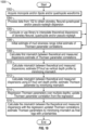
- the inversion workflow consists of several steps ( FIG. 10 ).
- the inversion is run by minimizing Equation 5, where the minimization can be achieved by random search or by grid search within the initial guess of dtm, as well as initial range of ⁇ , ⁇ , and ⁇ that are constrained by Equations 3 and 4.
- linear regression, non-linear regression or an eyeballing method may be used to optimize a mud slowness as a linear profile, multi-linear profile, or non-linear profile over logging depth.
- the mud slowness depth profiles can be associated with uncertainties that are obtained from the regression method.
- the inversion may be run again as the second step, where the range of dtm is reduced by using the regressed profile from the first step, with or without uncertainties.
- dtm now has a much narrower range or is a single value, the inverted Thomsen parameters can be more stable than the first step. Consequently, the linear regression, non-linear regression or an eyeballing method is applied to optimize the range among ⁇ , ⁇ , and ⁇ in the format of Equations 3 and 4.
- the regressions can give a new reduced range of k min , k max , l min , and l max .
- the inversion is run again using the newly regressed range of k min , k max , l min , and l max to get final results of the Thomsen parameters, with or without uncertainties.
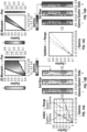
- FIG. 11 to FIG. 14 demonstrate synthetic examples of this data-driven physically constrained inversion method.
- 8 core sample data are used to generate synthetic Stoneley and flexural dispersions (track 5).
- track 5 synthetic Stoneley and flexural dispersions
- Track 1 to 4 plots the borehole diameter, formation density, compressional and shear slowness, respectively. The calculated mismatch is projected into mud slowness axis and is plotted in track 6.
- a linear mud slowness may be regressed using 2 parameters of a linear curve: the mud slowness value in the middle depth of the logging interval and mud slowness depth gradient, as shown in FIG. 12 . It can be seen that the regressed mud slowness profile matches very well with the true profile. However, we can also see the minimization of the Thomsen parameters is not well defined in this step. As described previously, a second step inversion using the regressed mud slowness is therefore necessary.
- FIG. 13 illustrates a case of how the regressed mud slowness can help to improve the stability of VTI parameters.
- five core samples are selected as inputs. These five core samples are taken from the same field so that the correlation between Thomsen parameters can represent a local range. For this case, a constant profile of mud slowness is assumed.
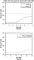
- the first step inversion is shown in FIG. 13A , where it can be seen, although there may be a mismatch map for the three Thomsen parameters from track 7 to track 9, their minimum values are with large uncertainties.
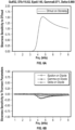
- mud slowness values are stacked to get an averaged value over the 5 depths and apply this averaged value to a second step inversion, as shown in FIG. 13C .
- the dashed lines in the tracks represent the uncertainties, which are computed by finding mismatch values less than 1 us/ft. With mud slowness stacked at 196 us/ft, estimation of the Thomsen parameters in step 2 now has much less uncertainties compared to step 1.
- FIG. 14 illustrates a case on how the updated correlation among the Thomsen parameters can help to further stabilize the inversion.
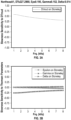
- FIG 14A shows the initial correlation between ⁇ and ⁇ .
- the second step inversion is shown in tracks 1 to 3 of FIG. 14B , where the dots are the mismatch peaks.
- FIG. 14C the peaks are overlaid over the 5 depths and then plotted as a cross-plot.
- this synthetic test core samples are used from the same field, so that a new reduced correlation between ⁇ and ⁇ can be regressed. For example, this localized relationship is obtained by a linear regression method, which gives 1.0 ⁇ ⁇ ⁇ ⁇ 1.6 ⁇ , as shown in the dashed line of FIG. 14C .
- a monopole and/or dipole and/or quadrupole waveform is acquired.
- the monopole and/or dipole and/or quadrupole waveform is processed to obtain Stoneley, flexural, quadrupole and/or pseudo-Rayleigh dispersion.
- Different methods such as TKO, SPI and SDICE may be used in 1004.
- TKO is described in Ekstrom, M.E., "Dispersion Estimation from Borehole Acoustic Arrays Using a Modified Matrix Pencil Algorithm," 29th Asilomar Conf. Signals Systems and Computing, Pacific Grove, CA, October 31, 1995 ..
- a computation may be performed or a library may be used to interpolate theoretical dispersions of Stoneley, flexural, quadrupole and/or Pseudo-Rayleigh.
- the method continues of performing an initial estimate of mud slowness range and an initial estimate of Thomsen parameter correlations.
- the method proceeds with calculating a mismatch between theoretical and measured dispersions.
- the value DTmud may be estimated as a vertical depth profile by minimizing the mismatch between the theoretical and measured dispersions.
- a second calculation of a mismatch between the theoretical and measured dispersions using the DTmud vertical depth profile is performed.
- Thomsen parameters may be estimated by minimizing the mismatch calculated in step 1010.
- Thomsen parameters are calculated over multiple depths.
- the Thomsen parameter values may be updated from the regression.
- a mismatch between the theoretical and measured dispersions is calculated with the regression updated parameters obtained in 1012.
- the Thomsen parameters may be estimated by minimizing the mismatch as final logs with uncertainties.
- the method may be performed wherein the waveform is generated from a wellbore sonic device.
- the method may be performed wherein the formation is an anisotropic formation.
Landscapes
- Physics & Mathematics (AREA)
- Life Sciences & Earth Sciences (AREA)
- Engineering & Computer Science (AREA)
- Remote Sensing (AREA)
- Geology (AREA)
- Environmental & Geological Engineering (AREA)
- Acoustics & Sound (AREA)
- General Life Sciences & Earth Sciences (AREA)
- General Physics & Mathematics (AREA)
- Geophysics (AREA)
- Geophysics And Detection Of Objects (AREA)
- Investigating Or Analyzing Materials By The Use Of Ultrasonic Waves (AREA)
- Ultra Sonic Daignosis Equipment (AREA)
- Sampling And Sample Adjustment (AREA)
Claims (8)
- Ein Verfahren, umfassend:Erhalten (1002) einer Wellenform aus einer akustischen Bohrlochvorrichtung in einer Formation;Verarbeiten (1004) der erhaltenen Wellenform, um mindestens eine von einer Stoneley-, Biege-, Quadrupol- und Pseudo-Rayleigh-Dispersion zu erhalten;mindestens eines von der Durchführung einer Berechnung und dem Verwenden einer Berechnung aus einer Bibliothek (1005) für interpolierte theoretische Dispersionen der Stoneley-, Biege-, Quadrupol- und Pseudo-Rayleigh-Dispersionen;Durchführen (1006) einer ersten Schätzung der Schlammverzögerung unter Verwendung sowohl der Verarbeitung der erhaltenen Wellenform als auch der Interpolation der theoretischen Dispersionen;Berechnen (1008) einer ersten Diskrepanz zwischen der verarbeiteten Wellenform, welche die mindestens eine Stoneley-, Biege-, Quadrupol- und Pseudo-Rayleigh-Dispersion erfasst, und den theoretischen Dispersionen der Stoneley-, Biege-, Quadrupol- und Pseudo-Rayleigh-Dispersionen;Schätzen (1008) von mindestens einem Delta-T-Wert des Schlamms als ein vertikales Tiefenprofil; gekennzeichnet durch:Berechnen (1010) einer zweiten Diskrepanz zwischen der theoretischen Dispersion und der verarbeiteten Wellenform unter Verwendung des mindestens einen geschätzten Delta-T-Werts des Schlamms;Schätzen (1010) von mindestens einem anisotropen Parameter durch Minimieren der zweiten Diskrepanz;Verwenden von Regression (1014) zum Berechnen des mindestens einen anisotropen Parameters über mehrere Tiefen;Aktualisieren (1014) der Werte für den mindestens einen anisotropen Parameter auf der Grundlage der Regression;Berechnen (1016) einer dritten Diskrepanz zwischen den theoretischen und den durch die akustische Bohrlochvorrichtung gemessenen Dispersionen auf der Grundlage der aktualisierten Werte für den mindestens einen auf der Regression basierenden Parameter;Schätzen (1016) eines Endwerts des mindestens einen anisotropen Parameters durch Minimieren einer Diskrepanz zwischen den theoretischen und den gemessenen Dispersionen; undVerwenden des Endwerts, um ein präziseres mechanisches Erdmodell (MEM) für die geomechanische Analyse zu erstellen.
- Das Verfahren nach Anspruch 1, wobei die Wellenform mindestens eine aus einer Monopol-, einer Dipol- und einer Quadrupol-Wellenform ist.
- Das Verfahren nach Anspruch 1, wobei das Verarbeiten (1004) der erhaltenen Wellenform zum Erhalten der mindestens einen von der Stoneley-, Biege-, Quadrupol- und Pseudo-Rayleigh-Dispersion eine von einer TKO-, SPI- und SDICE-Methode verwendet.
- Das Verfahren nach Anspruch 1, wobei der Delta-T-Wert des Schlamms durch Minimieren der Diskrepanz zwischen der theoretischen Dispersion und der gemessenen Dispersion geschätzt (1008) wird.
- Das Verfahren nach Anspruch 1, wobei der mindestens eine anisotrope Parameter, der durch Minimieren der zweiten Diskrepanz geschätzt (1010) wird, ein Thomsen-Parameter ist.
- Das Verfahren nach Anspruch 5, wobei der Thomsen-Parameter drei Thomsen-Parameter ist.
- Das Verfahren nach Anspruch 1, wobei der Endwert ein Thomsen-Parameter ist.
- Das Verfahren nach einem der vorangehenden Ansprüche, wobei eine Berechnung durchgeführt wird, um die theoretische Dispersion der Stoneley-, Biege-, Quadrupol- und Pseudo-Rayleigh-Dispersionen für die Wellenform zu erzeugen.
Applications Claiming Priority (2)
| Application Number | Priority Date | Filing Date | Title |
|---|---|---|---|
| US201962909429P | 2019-10-02 | 2019-10-02 | |
| PCT/US2020/053975 WO2021067725A1 (en) | 2019-10-02 | 2020-10-02 | A data driven method to invert for the formation anisotropic constants using borehole sonic data |
Publications (3)
| Publication Number | Publication Date |
|---|---|
| EP4038420A1 EP4038420A1 (de) | 2022-08-10 |
| EP4038420A4 EP4038420A4 (de) | 2023-10-18 |
| EP4038420B1 true EP4038420B1 (de) | 2024-10-23 |
Family
ID=75337543
Family Applications (1)
| Application Number | Title | Priority Date | Filing Date |
|---|---|---|---|
| EP20872125.8A Active EP4038420B1 (de) | 2019-10-02 | 2020-10-02 | Datengesteuertes verfahren zur invertierung für die bildung von anisotropen konstanten unter verwendung von bohrloch-schalldaten |
Country Status (6)
| Country | Link |
|---|---|
| US (1) | US11960043B2 (de) |
| EP (1) | EP4038420B1 (de) |
| CN (1) | CN114585949B (de) |
| DK (1) | DK4038420T3 (de) |
| SA (1) | SA522432136B1 (de) |
| WO (1) | WO2021067725A1 (de) |
Family Cites Families (17)
| Publication number | Priority date | Publication date | Assignee | Title |
|---|---|---|---|---|
| US4698793A (en) * | 1984-05-23 | 1987-10-06 | Schlumberger Technology Corporation | Methods for processing sonic data |
| US7660196B2 (en) * | 2004-05-17 | 2010-02-09 | Schlumberger Technology Corporation | Methods for processing dispersive acoustic waveforms |
| US7660195B2 (en) * | 2004-08-20 | 2010-02-09 | Halliburton Energy Services, Inc. | Attenuation mapping apparatus, systems, and methods |
| US7764572B2 (en) * | 2004-12-08 | 2010-07-27 | Schlumberger Technology Corporation | Methods and systems for acoustic waveform processing |
| CN100557464C (zh) * | 2007-01-15 | 2009-11-04 | 中国石油大港油田勘探开发研究院 | 基于叠前波场模拟的地震勘探层位标定方法 |
| US8456952B2 (en) * | 2008-10-03 | 2013-06-04 | Baker Hughes Incorporated | Curve-fitting technique for determining dispersion characteristics of guided elastic waves |
| US10436921B2 (en) * | 2011-07-27 | 2019-10-08 | Schlumberger Technology Corporation | Multi-well anisotropy inversion |
| BR112014023257A2 (pt) | 2012-04-02 | 2020-10-27 | Halliburton Energy Servicer, Inc. | método e sistema de perfilagem acústica |
| US20130322210A1 (en) * | 2012-06-05 | 2013-12-05 | Jefferrson Y. Alford | Methods and Apparatus for Modeling Formations |
| US9417352B2 (en) * | 2013-06-12 | 2016-08-16 | Schlumberger Technology Corporation | Multi-frequency inversion of modal dispersions for estimating formation anisotropy constants |
| CN104407381B (zh) * | 2014-12-17 | 2017-01-18 | 中国石油大学(华东) | 从井中弹性波速的径向变化获取地层岩石脆裂性质的方法 |
| US10353094B2 (en) * | 2015-03-30 | 2019-07-16 | Schlumberger Technology Corporation | Method for estimating anisotropic mechanical properties of a reservoir using sonic logging data |
| US20170115413A1 (en) * | 2015-10-27 | 2017-04-27 | Schlumberger Technology Corporation | Determining shear slowness from dipole source-based measurements aquired by a logging while drilling acoustic measurement tool |
| US11237288B2 (en) * | 2016-03-30 | 2022-02-01 | Halliburton Energy Services, Inc. | Verifying measurements of elastic anisotropy parameters in an anisotropic wellbore environment |
| GB2555137B (en) * | 2016-10-21 | 2021-06-30 | Schlumberger Technology Bv | Method and system for determining depths of drill cuttings |
| WO2018125058A1 (en) | 2016-12-27 | 2018-07-05 | Halliburton Energy Services, Inc. | Quasi-static stoneley slowness estimation |
| US11435493B2 (en) | 2017-06-15 | 2022-09-06 | Halliburton Energy Services, Inc. | Enhanced waveform analysis for target modes of borehole waves |
-
2020
- 2020-10-02 EP EP20872125.8A patent/EP4038420B1/de active Active
- 2020-10-02 WO PCT/US2020/053975 patent/WO2021067725A1/en not_active Ceased
- 2020-10-02 DK DK20872125.8T patent/DK4038420T3/da active
- 2020-10-02 US US17/754,395 patent/US11960043B2/en active Active
- 2020-10-02 CN CN202080074501.8A patent/CN114585949B/zh active Active
-
2022
- 2022-03-31 SA SA522432136A patent/SA522432136B1/ar unknown
Also Published As
| Publication number | Publication date |
|---|---|
| WO2021067725A1 (en) | 2021-04-08 |
| DK4038420T3 (en) | 2025-01-27 |
| US11960043B2 (en) | 2024-04-16 |
| CN114585949A (zh) | 2022-06-03 |
| SA522432136B1 (ar) | 2024-04-21 |
| US20220373707A1 (en) | 2022-11-24 |
| CN114585949B (zh) | 2026-03-31 |
| EP4038420A1 (de) | 2022-08-10 |
| EP4038420A4 (de) | 2023-10-18 |
Similar Documents
| Publication | Publication Date | Title |
|---|---|---|
| US12339410B2 (en) | Determining shear slowness from dipole source-based measurements acquired by a logging while drilling acoustic measurement tool | |
| US10175375B2 (en) | Method and system for direct slowness determination of dispersive waves in a wellbore environment | |
| US10539008B2 (en) | Systems and methods for determining tool center, borehole boundary, and/or mud parameter | |
| GB2426087A (en) | Determining characteristics of earth formations | |
| WO2014117009A1 (en) | Predicting mineralogy properties from elemental compositions | |
| US10359532B2 (en) | Methods to characterize formation properties | |
| US10324217B2 (en) | Method and system for real time determination of formation anisotropy, dip, and strike with MCI data | |
| Huang et al. | Inversion-based interpretation of borehole sonic measurements using semianalytical spatial sensitivity functions | |
| WO2014084751A1 (en) | A method for processing acoustic waveforms | |
| Tang et al. | Borehole acoustic full-waveform inversion | |
| Maalouf et al. | Inversion-based method to mitigate noise in borehole sonic logs | |
| Saputra et al. | Adaptive multidimensional inversion for borehole ultra-deep azimuthal resistivity | |
| WO2017172371A1 (en) | Verifying measurements of elastic anisotropy parameters in an anisotropic wellbore environment | |
| Mukhopadhyay et al. | The differential-phase based time-and frequency-semblance algorithm for array-acoustic processing and its application to formation-slowness measurement | |
| Maalouf et al. | Interpretation of borehole sonic measurements acquired in vertical transversely isotropic formations penetrated by vertical wells | |
| US8411529B2 (en) | Walkaway VSP calibrated sonic logs | |
| Sun et al. | Evaluation of resistivity anisotropy and formation dip from directional electromagnetic tools while drilling | |
| EP4038420B1 (de) | Datengesteuertes verfahren zur invertierung für die bildung von anisotropen konstanten unter verwendung von bohrloch-schalldaten | |
| Hou et al. | Characterization of formation fractures with multicomponent induction logging based on biaxial anisotropy models: Method and case studies | |
| Tang et al. | Estimating formation permeability and anistoropy from borehole stoneley waves | |
| Mallan et al. | Simulation of borehole sonic waveforms in dipping, anisotropic, and invaded formations | |
| US10429532B2 (en) | System and methodology for estimating formation elastic properties using decomposed and undecomposed signal | |
| Donald et al. | Digital transformation of borehole sonic services in the oil and gas industry | |
| Sviridov et al. | Reservoir mapping with vendor-independent gradient-based stochastic inversion of LWD ultra-deep azimuthal resistivity data | |
| Zhang et al. | 2D anisotropic inversion of multicomponent induction logging data |
Legal Events
| Date | Code | Title | Description |
|---|---|---|---|
| STAA | Information on the status of an ep patent application or granted ep patent |
Free format text: STATUS: THE INTERNATIONAL PUBLICATION HAS BEEN MADE |
|
| PUAI | Public reference made under article 153(3) epc to a published international application that has entered the european phase |
Free format text: ORIGINAL CODE: 0009012 |
|
| STAA | Information on the status of an ep patent application or granted ep patent |
Free format text: STATUS: REQUEST FOR EXAMINATION WAS MADE |
|
| 17P | Request for examination filed |
Effective date: 20220401 |
|
| AK | Designated contracting states |
Kind code of ref document: A1 Designated state(s): AL AT BE BG CH CY CZ DE DK EE ES FI FR GB GR HR HU IE IS IT LI LT LU LV MC MK MT NL NO PL PT RO RS SE SI SK SM TR |
|
| DAV | Request for validation of the european patent (deleted) | ||
| DAX | Request for extension of the european patent (deleted) | ||
| A4 | Supplementary search report drawn up and despatched |
Effective date: 20230919 |
|
| RIC1 | Information provided on ipc code assigned before grant |
Ipc: G01V 1/50 20060101ALI20230913BHEP Ipc: G01V 1/28 20060101ALI20230913BHEP Ipc: G01V 1/30 20060101AFI20230913BHEP |
|
| GRAP | Despatch of communication of intention to grant a patent |
Free format text: ORIGINAL CODE: EPIDOSNIGR1 |
|
| STAA | Information on the status of an ep patent application or granted ep patent |
Free format text: STATUS: GRANT OF PATENT IS INTENDED |
|
| RIC1 | Information provided on ipc code assigned before grant |
Ipc: G01V 1/50 20060101ALI20240523BHEP Ipc: G01V 1/28 20060101ALI20240523BHEP Ipc: G01V 1/30 20060101AFI20240523BHEP |
|
| INTG | Intention to grant announced |
Effective date: 20240625 |
|
| RAP3 | Party data changed (applicant data changed or rights of an application transferred) |
Owner name: SCHLUMBERGER TECHNOLOGY B.V. Owner name: SERVICES PETROLIERS SCHLUMBERGER |
|
| GRAS | Grant fee paid |
Free format text: ORIGINAL CODE: EPIDOSNIGR3 |
|
| GRAA | (expected) grant |
Free format text: ORIGINAL CODE: 0009210 |
|
| STAA | Information on the status of an ep patent application or granted ep patent |
Free format text: STATUS: THE PATENT HAS BEEN GRANTED |
|
| AK | Designated contracting states |
Kind code of ref document: B1 Designated state(s): AL AT BE BG CH CY CZ DE DK EE ES FI FR GB GR HR HU IE IS IT LI LT LU LV MC MK MT NL NO PL PT RO RS SE SI SK SM TR |
|
| REG | Reference to a national code |
Ref country code: GB Ref legal event code: FG4D |
|
| REG | Reference to a national code |
Ref country code: CH Ref legal event code: EP |
|
| REG | Reference to a national code |
Ref country code: DE Ref legal event code: R096 Ref document number: 602020040075 Country of ref document: DE |
|
| REG | Reference to a national code |
Ref country code: IE Ref legal event code: FG4D |
|
| REG | Reference to a national code |
Ref country code: DK Ref legal event code: T3 Effective date: 20250123 |
|
| REG | Reference to a national code |
Ref country code: NL Ref legal event code: FP |
|
| REG | Reference to a national code |
Ref country code: LT Ref legal event code: MG9D |
|
| REG | Reference to a national code |
Ref country code: AT Ref legal event code: MK05 Ref document number: 1735278 Country of ref document: AT Kind code of ref document: T Effective date: 20241023 |
|
| PG25 | Lapsed in a contracting state [announced via postgrant information from national office to epo] |
Ref country code: PT Free format text: LAPSE BECAUSE OF FAILURE TO SUBMIT A TRANSLATION OF THE DESCRIPTION OR TO PAY THE FEE WITHIN THE PRESCRIBED TIME-LIMIT Effective date: 20250224 Ref country code: IS Free format text: LAPSE BECAUSE OF FAILURE TO SUBMIT A TRANSLATION OF THE DESCRIPTION OR TO PAY THE FEE WITHIN THE PRESCRIBED TIME-LIMIT Effective date: 20250223 Ref country code: HR Free format text: LAPSE BECAUSE OF FAILURE TO SUBMIT A TRANSLATION OF THE DESCRIPTION OR TO PAY THE FEE WITHIN THE PRESCRIBED TIME-LIMIT Effective date: 20241023 |
|
| PG25 | Lapsed in a contracting state [announced via postgrant information from national office to epo] |
Ref country code: FI Free format text: LAPSE BECAUSE OF FAILURE TO SUBMIT A TRANSLATION OF THE DESCRIPTION OR TO PAY THE FEE WITHIN THE PRESCRIBED TIME-LIMIT Effective date: 20241023 |
|
| PG25 | Lapsed in a contracting state [announced via postgrant information from national office to epo] |
Ref country code: BG Free format text: LAPSE BECAUSE OF FAILURE TO SUBMIT A TRANSLATION OF THE DESCRIPTION OR TO PAY THE FEE WITHIN THE PRESCRIBED TIME-LIMIT Effective date: 20241023 |
|
| PG25 | Lapsed in a contracting state [announced via postgrant information from national office to epo] |
Ref country code: ES Free format text: LAPSE BECAUSE OF FAILURE TO SUBMIT A TRANSLATION OF THE DESCRIPTION OR TO PAY THE FEE WITHIN THE PRESCRIBED TIME-LIMIT Effective date: 20241023 |
|
| PG25 | Lapsed in a contracting state [announced via postgrant information from national office to epo] |
Ref country code: LV Free format text: LAPSE BECAUSE OF FAILURE TO SUBMIT A TRANSLATION OF THE DESCRIPTION OR TO PAY THE FEE WITHIN THE PRESCRIBED TIME-LIMIT Effective date: 20241023 Ref country code: GR Free format text: LAPSE BECAUSE OF FAILURE TO SUBMIT A TRANSLATION OF THE DESCRIPTION OR TO PAY THE FEE WITHIN THE PRESCRIBED TIME-LIMIT Effective date: 20250124 Ref country code: AT Free format text: LAPSE BECAUSE OF FAILURE TO SUBMIT A TRANSLATION OF THE DESCRIPTION OR TO PAY THE FEE WITHIN THE PRESCRIBED TIME-LIMIT Effective date: 20241023 |
|
| PG25 | Lapsed in a contracting state [announced via postgrant information from national office to epo] |
Ref country code: PL Free format text: LAPSE BECAUSE OF FAILURE TO SUBMIT A TRANSLATION OF THE DESCRIPTION OR TO PAY THE FEE WITHIN THE PRESCRIBED TIME-LIMIT Effective date: 20241023 |
|
| PG25 | Lapsed in a contracting state [announced via postgrant information from national office to epo] |
Ref country code: RS Free format text: LAPSE BECAUSE OF FAILURE TO SUBMIT A TRANSLATION OF THE DESCRIPTION OR TO PAY THE FEE WITHIN THE PRESCRIBED TIME-LIMIT Effective date: 20250123 |
|
| PG25 | Lapsed in a contracting state [announced via postgrant information from national office to epo] |
Ref country code: SM Free format text: LAPSE BECAUSE OF FAILURE TO SUBMIT A TRANSLATION OF THE DESCRIPTION OR TO PAY THE FEE WITHIN THE PRESCRIBED TIME-LIMIT Effective date: 20241023 |
|
| PG25 | Lapsed in a contracting state [announced via postgrant information from national office to epo] |
Ref country code: EE Free format text: LAPSE BECAUSE OF FAILURE TO SUBMIT A TRANSLATION OF THE DESCRIPTION OR TO PAY THE FEE WITHIN THE PRESCRIBED TIME-LIMIT Effective date: 20241023 |
|
| PG25 | Lapsed in a contracting state [announced via postgrant information from national office to epo] |
Ref country code: RO Free format text: LAPSE BECAUSE OF FAILURE TO SUBMIT A TRANSLATION OF THE DESCRIPTION OR TO PAY THE FEE WITHIN THE PRESCRIBED TIME-LIMIT Effective date: 20241023 |
|
| REG | Reference to a national code |
Ref country code: DE Ref legal event code: R097 Ref document number: 602020040075 Country of ref document: DE |
|
| PG25 | Lapsed in a contracting state [announced via postgrant information from national office to epo] |
Ref country code: SK Free format text: LAPSE BECAUSE OF FAILURE TO SUBMIT A TRANSLATION OF THE DESCRIPTION OR TO PAY THE FEE WITHIN THE PRESCRIBED TIME-LIMIT Effective date: 20241023 |
|
| PG25 | Lapsed in a contracting state [announced via postgrant information from national office to epo] |
Ref country code: CZ Free format text: LAPSE BECAUSE OF FAILURE TO SUBMIT A TRANSLATION OF THE DESCRIPTION OR TO PAY THE FEE WITHIN THE PRESCRIBED TIME-LIMIT Effective date: 20241023 |
|
| PLBE | No opposition filed within time limit |
Free format text: ORIGINAL CODE: 0009261 |
|
| STAA | Information on the status of an ep patent application or granted ep patent |
Free format text: STATUS: NO OPPOSITION FILED WITHIN TIME LIMIT |
|
| PG25 | Lapsed in a contracting state [announced via postgrant information from national office to epo] |
Ref country code: SE Free format text: LAPSE BECAUSE OF FAILURE TO SUBMIT A TRANSLATION OF THE DESCRIPTION OR TO PAY THE FEE WITHIN THE PRESCRIBED TIME-LIMIT Effective date: 20241023 |
|
| PGFP | Annual fee paid to national office [announced via postgrant information from national office to epo] |
Ref country code: NL Payment date: 20250826 Year of fee payment: 6 |
|
| 26N | No opposition filed |
Effective date: 20250724 |
|
| PGFP | Annual fee paid to national office [announced via postgrant information from national office to epo] |
Ref country code: IT Payment date: 20250922 Year of fee payment: 6 |
|
| PGFP | Annual fee paid to national office [announced via postgrant information from national office to epo] |
Ref country code: GB Payment date: 20250821 Year of fee payment: 6 |
|
| PGFP | Annual fee paid to national office [announced via postgrant information from national office to epo] |
Ref country code: FR Payment date: 20250821 Year of fee payment: 6 |
|
| REG | Reference to a national code |
Ref country code: CH Ref legal event code: U11 Free format text: ST27 STATUS EVENT CODE: U-0-0-U10-U11 (AS PROVIDED BY THE NATIONAL OFFICE) Effective date: 20251101 |
|
| PGFP | Annual fee paid to national office [announced via postgrant information from national office to epo] |
Ref country code: NO Payment date: 20251009 Year of fee payment: 6 |
|
| PGFP | Annual fee paid to national office [announced via postgrant information from national office to epo] |
Ref country code: DK Payment date: 20251014 Year of fee payment: 6 |
|
| PGFP | Annual fee paid to national office [announced via postgrant information from national office to epo] |
Ref country code: CH Payment date: 20251101 Year of fee payment: 6 |