EP4038434B1 - Dispositifs et procédés de caractérisation de l'orientation 3d de dipôles électroluminescents - Google Patents
Dispositifs et procédés de caractérisation de l'orientation 3d de dipôles électroluminescents Download PDFInfo
- Publication number
- EP4038434B1 EP4038434B1 EP20793265.8A EP20793265A EP4038434B1 EP 4038434 B1 EP4038434 B1 EP 4038434B1 EP 20793265 A EP20793265 A EP 20793265A EP 4038434 B1 EP4038434 B1 EP 4038434B1
- Authority
- EP
- European Patent Office
- Prior art keywords
- orientation
- aperture
- plane
- objective lens
- detection
- Prior art date
- Legal status (The legal status is an assumption and is not a legal conclusion. Google has not performed a legal analysis and makes no representation as to the accuracy of the status listed.)
- Active
Links
Images




Classifications
-
- G—PHYSICS
- G02—OPTICS
- G02B—OPTICAL ELEMENTS, SYSTEMS OR APPARATUS
- G02B21/00—Microscopes
- G02B21/16—Microscopes adapted for ultraviolet illumination ; Fluorescence microscopes
-
- G—PHYSICS
- G02—OPTICS
- G02B—OPTICAL ELEMENTS, SYSTEMS OR APPARATUS
- G02B21/00—Microscopes
- G02B21/36—Microscopes arranged for photographic purposes or projection purposes or digital imaging or video purposes including associated control and data processing arrangements
- G02B21/361—Optical details, e.g. image relay to the camera or image sensor
-
- G—PHYSICS
- G02—OPTICS
- G02B—OPTICAL ELEMENTS, SYSTEMS OR APPARATUS
- G02B21/00—Microscopes
- G02B21/36—Microscopes arranged for photographic purposes or projection purposes or digital imaging or video purposes including associated control and data processing arrangements
- G02B21/365—Control or image processing arrangements for digital or video microscopes
- G02B21/367—Control or image processing arrangements for digital or video microscopes providing an output produced by processing a plurality of individual source images, e.g. image tiling, montage, composite images, depth sectioning, image comparison
-
- G—PHYSICS
- G02—OPTICS
- G02B—OPTICAL ELEMENTS, SYSTEMS OR APPARATUS
- G02B27/00—Optical systems or apparatus not provided for by any of the groups G02B1/00 - G02B26/00, G02B30/00
- G02B27/28—Optical systems or apparatus not provided for by any of the groups G02B1/00 - G02B26/00, G02B30/00 for polarising
- G02B27/283—Optical systems or apparatus not provided for by any of the groups G02B1/00 - G02B26/00, G02B30/00 for polarising used for beam splitting or combining
-
- G—PHYSICS
- G01—MEASURING; TESTING
- G01N—INVESTIGATING OR ANALYSING MATERIALS BY DETERMINING THEIR CHEMICAL OR PHYSICAL PROPERTIES
- G01N21/00—Investigating or analysing materials by the use of optical means, i.e. using sub-millimetre waves, infrared, visible or ultraviolet light
- G01N21/62—Systems in which the material investigated is excited whereby it emits light or causes a change in wavelength of the incident light
- G01N21/63—Systems in which the material investigated is excited whereby it emits light or causes a change in wavelength of the incident light optically excited
- G01N21/64—Fluorescence; Phosphorescence
- G01N21/6445—Measuring fluorescence polarisation
-
- G—PHYSICS
- G01—MEASURING; TESTING
- G01N—INVESTIGATING OR ANALYSING MATERIALS BY DETERMINING THEIR CHEMICAL OR PHYSICAL PROPERTIES
- G01N21/00—Investigating or analysing materials by the use of optical means, i.e. using sub-millimetre waves, infrared, visible or ultraviolet light
- G01N21/62—Systems in which the material investigated is excited whereby it emits light or causes a change in wavelength of the incident light
- G01N21/63—Systems in which the material investigated is excited whereby it emits light or causes a change in wavelength of the incident light optically excited
- G01N21/64—Fluorescence; Phosphorescence
- G01N21/645—Specially adapted constructive features of fluorimeters
- G01N21/6456—Spatial resolved fluorescence measurements; Imaging
- G01N21/6458—Fluorescence microscopy
Definitions
- the present disclosure relates to devices and methods for the characterization of the 3D orientation of light emitting dipoles. It further relates to a microscopy system including such device.
- Super-resolved optical imaging using the spatial localization of isolated molecules is experiencing rapid developments and represents an important contribution of the imaging devices used in biology.
- these instruments do not enable to determine the orientation in space of the molecules considered.
- Accurate knowledge of the 3D orientation of an isolated molecule is important for different reasons. First, the orientation of the molecule can modify the determination of its spatial location. Second, knowing the 3D orientation of the molecule enables to get a structural and conformational information of such molecules, e.g. a protein, in addition to the localization information.
- FIG. 1 shows the different parameters used in the present description to characterize the 3D orientation of a molecule 10 within a specimen, and more generally an emitting dipole, schematized by an arrow 14 in FIG. 1 .
- the 3D orientation may be characterized by a distribution of the orientation during a given measurement time.
- Such orientation distribution may be defined by a cone 12 of mean orientation ( ⁇ , ⁇ ) in a frame (X, Y, Z) of the specimen, and of angular aperture (or "wobbling") ⁇ .
- the angular aperture of the cone also corresponds to the extent of the angular fluctuation of the orientation within a measurement time.
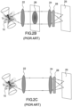
- FIG. 2A A first approach, based on defocus or extended imaging, is shown schematically in FIG. 2A and described for example in Toprak et al. "Defocused orientation and position imaging (DOPI) of myosin V", Proc. Natl. Acad. Sci. USA 103, 6495-6499 (2006 ) or in Aguet et al. “Superresolution orientation estimation and localization of fluorescent dipoles using 3-D steerable filters", Opt. Express 17, 6829-6848 (2009 ).
- DOPI Defocused orientation and position imaging
- a molecule 10 within a specimen is imaged using an objective lens 22 and a tube lens 24 in a detection plane of a detector 25, wherein the detection plane is defocused.
- the analysis of the shape of the image, or deformed point spread function (PSF) may inform on the 3D orientation of the molecule if such deformed PSF is sufficiently pixelized.
- the above technique requires very low aberrations of the optical system as the shape of the PSFs connected to each orientation of space needs to be known a priori.
- this approach involves a significant increase in the size of the PSFs of isolated molecules, only specimen with low molecule density can be characterized, and only specimen with very bright molecules.
- Complex and heavy algorithmic tools are required to determine the molecular orientation of the molecules from the deformation of the PSFs and the angular fluctuation (wobbling) cannot be determined.
- phase mask 26 for example implemented by a spatial light modulator (SLM)
- SLM spatial light modulator
- the phase mask e.g. a bisected pupil phase mask
- BFP back focal plane
- a polarizing beam splitter 28 splits light from the specimen as passed via the phase mask 26 and an imaging lens 24 (tube lens) into two imaging channels, to a detector 25.
- the light detected by the detector 25 includes characteristics indicative of the rotational mobility.
- a third approach doesn't require a deformation of the PSF. It is based on the decomposition of light according to different states of polarization, on emission or detection, and is described for example in Valades Cruz et al. "Quantitative nanoscale imaging of orientational order in biological filaments by polarized super-resolution microscopy", Proc. Natl. Acad. Sci. 113 (7) E820-E828 (2016 ) as well as in Shalin B. Mehta et al. "Dissection of molecular assembly dynamics by tracking orientation and position of single molecules in live cells", Proc. Natl. Acad. Sci. 113 (42) E6352-E6361 (2016 ), and in M.
- Such approach implements a two- or four-polarization detection scheme using a polarizing beam splitter 28. Signals acquired by the detector 25 for the different states of polarization are compared to retrieve an information on the 2D orientation of a molecule 10 within a specimen.
- the present description proposes a new method for characterizing the 3D orientation of an emitting dipole which can be implemented using a simple experimental arrangement compared to the prior art, and which enables to have access to all parameters of the 3D orientation, including the wobbling, with direct data processing. Further, the proposed method doesn't require a deformation of the PSF; it can therefore be applied to the characterization of the 3D orientation of emitting dipoles in dense specimen.
- the term "about” means the same as a margin lower and/or greater than 10%, for example 5%, of the respective value.
- the present disclosure relates to a method for the characterization of the 3D orientation of at least one emitting dipole within a specimen, wherein the specimen is positioned in a front focal plane of a microscope objective lens with a given numerical aperture, the method comprising:
- An emitting dipole is for example one of the following : a fluorescent molecule attached to a protein of interest in a cell or tissue; a fluorescent nanoparticle (e.g. a quantum dot); a nonlinear nanocrystal (for instant active for second harmonic generation); a nonlinear label free emitter in a biological sample (e.g. collagen for second harmonic generation, lipid for coherent anti stokes Raman scattering).
- a fluorescent nanoparticle e.g. a quantum dot
- a nonlinear nanocrystal for instant active for second harmonic generation
- a nonlinear label free emitter in a biological sample e.g. collagen for second harmonic generation, lipid for coherent anti stokes Raman scattering.
- the specimen is for example one of the following: a cell labelled with fluorescent molecules labelling some particular proteins of interest (e.g. actin, microtubules, membrane proteins, lipid probes of the plasma membrane); a biological tissue imaged using label free methods such as nonlinear imaging.
- proteins of interest e.g. actin, microtubules, membrane proteins, lipid probes of the plasma membrane
- label free methods such as nonlinear imaging.
- said frame of the sample is an orthonormal 3D system consisting of an ordered triplet of axis (X, Y, Z) which are pair-wise perpendicular.
- X, Y, Z axis
- the Z axis is parallel to an optical axis of the microscope objective lens.
- the directions of polarization are defined in a frame (X', Y', Z') in the detection plane corresponding (i.e. optically conjugated) to said frame (X, Y, Z) of the specimen used to determine the mean orientation and angular aperture of the 3D orientation of the at least one emitting dipole.
- the 0° direction of polarization is parallel to the X' direction of the frame defined in the detection unit and the directions of polarization are angularly spaced in the X'Y' plane of the plane defined in the detection unit.
- the proposed method thus implements a four-polarization detection scheme, wherein the beams in two of said four polarization detection channels are spatially filtered in a plane optically conjugated with the back focal plane of the microscope.
- the applicants have shown that such detection scheme enables to retrieve, from the data processing of the corresponding four intensity images, all three parameters of the orientation of the emitting dipole (mean orientation and wobbling).
- each pixel of the image represents the optical response from a collection of dipoles spatially averaged within the size of the optical resolution of the microscope objective, and temporally averaged over the integration time of the intensity images.
- This collection of dipoles represents a distribution, oriented towards a given 3D mean direction within a cone of aperture which comprises the wobbling of each individual dipole as well as the alignment aperture of all dipoles.
- the spatial filtering of the first beam results from a limitation of the aperture in the filtering plane optically conjugated with the back focal plane of the microscope objective lens. Said limitation if for example obtained using a spatial filter comprising a disc shaped aperture with an inner radius smaller than the full aperture of the first beam in said filtering plane, wherein said full aperture is only limited by the numerical aperture of the microscope objective lens.
- a ratio between said limited aperture of said first beam in the filtering plane and said full aperture of said first beam in the filtering plane is smaller than about 0.8, preferably comprised between about 0.2 and about 0.8, preferably between about 0. 5 and about 0.8, for example equal to about 0.7.
- ratio is a good compromise between the quantity of photons required for the image formation and the precision of the extracted information on the 3D orientation of the emitting dipole. If the ratio is too low, depending on the brightness of the molecules under study, the signal may be too low in the detection plane. On the other hand, if the ratio is greater than about 0.8, the applicants have shown that the 3D orientation of the molecule may not be retrieved in an unambiguous manner, while if the ratio is smaller than about 0.8, its value doesn't have an impact on the precision of the determined value of the 3D orientation.
- said four directions of polarization are angularly spaced in four separate identical sectors (or "quadrants") of the [0 - 180°] range of directions.
- quadrants or "quadrants”
- said four directions of polarization are regularly angularly spaced in said four separate quadrants. Regularly angularly spacing the four directions of polarization enables to simplify at most the relationship between the measured intensities and the retrieved parameters. For example, said four directions of polarization are spaced by an angle of 45°, e.g. using four directions of polarizations equal to 0°, 45°, 90°, 135°.
- determining the mean orientation and the angular aperture of the distribution of the 3D orientation of said at least one emitting dipole comprises:
- the present disclosure relates to devices for the implementation of embodiments of methods according to the first aspect.
- the present disclosure relates to a device for the characterization of the 3D orientation of at least one emitting dipole within a specimen, wherein said device is configured to be connected to a microscope system comprising a microscope objective lens with a given numerical aperture and a detection unit having a detection plane optically conjugated with a front focal plane of said microscope objective lens.
- the device according to the second aspect comprises:
- the calculation unit is referred as a single component but may comprise a plurality of distinct electronic components.
- the calculation unit can for instance be, or comprise, a processing unit such as a central processing unit (CPU), a graphic processing unit (GPU), a Field Programmable Gate Array (FPGA), an Application-Specific Integrated Circuit (ASIC) and/or any type of such processing unit known in the art.
- CPU central processing unit
- GPU graphic processing unit
- FPGA Field Programmable Gate Array
- ASIC Application-Specific Integrated Circuit
- the spatial frequency filter is configured to limit the aperture of the first beam in the filtering plane by comparison to a full aperture of the first beam in said filtering plane, wherein said full aperture is only limited by the numerical aperture of the microscope objective lens.
- a ratio between said limited aperture of said first beam in the filtering plane and said full aperture of said first beam in the filtering plane is smaller than about 0.8, preferably comprised between about 0.2 and about 0.8, preferably between about 0. 5 and about 0.8, for example equal to about 0.7.
- the spatial frequency filter is configured to work in transmission and comprises a disc shaped aperture having a given inner radius.
- the spatial frequency filter may also be configured to work in reflection.
- it comprises an inclined elliptic shaped mirror, having given external dimensions, the elliptical shape of the mirror enabling to take into account the projection of the first beam on the inclined mirror.
- said first and second polarizing beam splitters respectively comprise polarizing beam splitter cubes or Wollaston beam splitters.
- the first and second polarizing beam splitters may further comprise a half wave plate arranged before said polarizing beam splitter cubes or Wollaston beam splitters.
- the polarizing beam splitter cubes or Wollaston beam splitters are oriented with angles corresponding to the required polarization projection directions in order to obtain said four beams linearly polarized, each having a specific direction of polarization.
- said four directions of polarization are angularly spaced in four separate quadrants of the [0 - 180°] range of directions.
- the device further comprises a relay lens for optically conjugating the back focal plane of the microscope with said filtering plane.
- the present disclosure relates to microscope systems implementing embodiments of devices according to the second aspect.
- a microscope system according to the third aspect of the disclosure comprises a microscope objective lens with a given numerical aperture, a detection unit and a device according to the second aspect.
- the microscope system is configured to work in one of the following illumination configurations: wide field illumination, TIR (for " Total Internal Reflection ”) illumination, scanning illumination.
- the microscope system is configured to work in one of the following detection configurations: pure wide field fluorescence imaging, STORM (for "Stochastic Optical Reconstruction Microscopy"), PALM (for "Photoactivated Localization Microscopy”), nonlinear imaging.
- Nonlinear imaging may be performed in a "descanned” configuration, according to which a same scanning mirror is used for detection and emission, the emission being spectrally separated from the excitation using a dichroic plate placed after the scanning mirror.
- Nonlinear imaging may also be performed in a "non-descanned” configuration, according to which detection is not made using the same scanning mirror as emission. Emission may use a dichroic mirror placed just below the microscope objective lens and detection may be made using point detectors collecting the light emitted by each point of the front focal plane of the microscope objective lens.
- FIG. 3 is a schematic of a microscope system 300 implementing a device 301 according to an embodiment of the present description.
- the microscope system 300 generally comprises a microscope objective lens 302 with a given numerical aperture NA and a detection unit 303.
- a specimen 11 with light emitting dipoles is positioned in a front focal plane P 1 of the microscope objective lens.
- the microscope system further comprises a tube lens 304 forming an intermediate focal plane P' 1 , optically conjugated with a plane of the specimen.
- the microscope system illustrated in FIG. 3 is for example a wide field or TIR illumination microscope.
- the microscope system as shown in FIG. 3 may also comprise an illumination and/or a detection scheme adapted for other functionalities, for example scanned or descanned detection schemes.
- the microscope system 300 further comprises a device 301 for the characterization of the 3D orientation of at least one emitting dipole within the specimen 11.
- the device 301 comprises a non-polarizing beam splitter 314 configured to split a light beam B 0 emitted by at least one emitting dipole of the specimen and exiting the objective lens 302 and the tube lens 304, into first and second beams B 1 , B 2 , thus forming a first detection channel and a second detection channel.
- the device 301 further comprises a spatial frequency filter 315 arranged in the first detection channel, and configured for spatially filtering the first beam to select a given range of spatial low frequencies.
- the spatial frequency filter 315 is positioned in a filtering plane P 2 conjugated with a back focal plane of the microscope objective lens 302.
- the device 301 further comprises a relay lens 312 for optically conjugating the back focal plane of the microscope with the filtering plane P 2 .
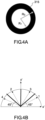
- such spatial frequency filter 315 may work in transmission and comprise a disc-shaped aperture having an inner radius R 1 and an outer radius R 0 .
- the outer radius is determined to cover the full detection aperture, i.e.: R 0 ⁇ N A . f / M
- NA is the numerical aperture of the objective lens 302
- f is the focal length of the relay lens 312
- M is the microscope magnification.
- the spatial frequency filter 315 may also work in reflection.
- it may comprise for example an elliptic shaped mirror whose dimensions are determined to take into account the angle of incidence of the first beam on said mirror in order to achieve the desired spatial limitation of the first beam.
- the first and second detection channels comprise respectively a first polarizing beam splitter 318 and a second polarizing beam splitter 326, 328.
- the first and second polarizing beam splitters are configured to split respectively the filtered first beam and the second beam to provide four beams linearly polarized LP 1 , LP 2 , LP 3 , LP 4 , each having a specific direction of polarization.
- the first polarizing beam splitter may comprise for example a Wollaston prism 318 or a polarizing beam splitter cube.
- an extra mirror (not shown in FIG. 3 ) may be used to fold back towards the detection unit 303 one of the polarized beams that propagate with an angle 90° between each other.
- the second polarizing beam splitter may comprise for example a Wollaston prism 328 before which is arranged a half wave plate 326 or a polarizing beam splitter cube before which is arranged a half wave plate 326.
- the first and second detection channels may also comprise respectively a first lens 316 and a second lens 324 to optically conjugate the front focal plane P 1 and the detection plane P" 1 .
- the second detection channel further comprises a mirror 322 to direct the second beam towards the polarizing beam splitter 326, 328 and a detection unit 303.
- the detection unit 303 may comprise a sensitive CCD (charge coupled device) camera or a scientific CMOS (sCMOS) camera. In the case of scanning microscopy (in both scanned and descanned versions), the detection unit may comprise a point detector such as a Photomultiplier or sensitive photodiode.
- CCD charge coupled device
- sCMOS scientific CMOS
- the detection unit may comprise a point detector such as a Photomultiplier or sensitive photodiode.
- the detection unit 303 comprises a detection plane P" 1 optically conjugated with the plane P 1 of the specimen (or front focal plane of the microscope objective lens) and acquires 4 intensity images I 1 , I 2 , I 3 , I 4 resulting from the detection of the four linearly polarized beams LP 1 , LP 2 , LP 3 , LP 4 .
- the device 301 further comprises a calculation unit 305 configured to determine, from the four intensity images I 1 , I 2 , I 3 , I 4 , the mean orientation ( ⁇ , ⁇ ) and the angular aperture ( ⁇ ) of the distribution of the 3D orientation of at least one emitting dipole, as explained below.
- the directions of polarization are defined in a frame (X', Y', Z') of the detection plane, wherein the frame (X', Y', Z') is optically conjugated with a predefined frame (X, Y, Z) of the specimen used to determine the mean orientation and angular aperture of the 3D orientation of at least one emitting dipole. More specifically, by convention in the present direction, the Z axis is parallel to an optical axis of the microscope objective lens. The directions of polarization are thus angularly spaced in the X'Y' plane, and by convention, the 0° direction of polarization is parallel to the X' direction, also referred below as the "horizontal axis".
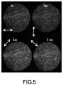
- image intensities are images of single molecules of AlexaFluor488 attached to actin fibers in fixed cells.
- Images were obtained using a normal-incidence illumination of a cell with an illumination laser diode at 488 nm, and an objective lens of numerical aperture 1.45 for excitation and collection of the fluorescence signal.
- a ratio ⁇ between the apertures of the detection channels was fixed at 0.7.
- Each bright spot of the images represents the image of a fluorescent single molecule.
- the visible structures show actin fibers within the cell, each image full size is 30 ⁇ m.
- the section below describes how the parameters ( ⁇ , ⁇ , ⁇ ) can be retrieved per pixel/region in an image, based on the measurement of the four intensities ( I 1 , I 2 , I 3 , I 4 ) resulting from detection of the four beams linearly polarized LP 1 , LP 2 , LP 3 , LP 4 .
- the region of integration is the isolated point spread function of the single molecule (e.g. its image spot).
- the radiated intensity I i ⁇ along the analyser direction i can be expressed in the Fourier plane P 2 of the imaging system (or back focal plane image) with local cylindrical coordinates ( ⁇ , ⁇ ) ( FIG. 6A ). Even though the projection on the polarization direction is physically performed just before the image plane, it is convenient, for calculations, to express projected intensities right at the back focal plane, where the integrations over the used apertures are performed. Intensities calculated at the back focal plane are in the end equivalent to intensities calculated in the image plane.
- I i ⁇ ⁇ E i X ⁇ ⁇ ⁇ E i Y ⁇ ⁇ E i Z ⁇ ⁇ ⁇ . ⁇ T ⁇ ⁇ . E i X ⁇ ⁇ E i Y ⁇ ⁇ E i Z ⁇ ⁇
- the total intensity measured is the sum over all dipoles' directions explored during the measurement time and over the number of molecules detected in a given pixel.
- I i ⁇ ⁇ I i ⁇ a ⁇ ⁇ + I i ⁇ b ⁇ ⁇ + I i ⁇ c ⁇ ⁇
- the signal is summed over the corresponding back focal plane aperture (full numerical aperture for channels ( 1 , 2 ), reduced numerical aperture for channels ( 3,4 )):
- NA numerical aperture of the objective and n the refractive index of the immersion medium.
- ⁇ X , ⁇ Y and ⁇ Z are introduced to account for the excitation efficiencies (e.g. excitation fields amplitudes) along the directions X,Y,Z.
- excitation efficiencies e.g. excitation fields amplitudes
- the K matrix contains all terms concerning the optical propagation (e.g. NA, polarization projection directions, ⁇ , wavelength detected ⁇ ), while the M vector contains information on the dipoles' orientation parameters (e.g. ( ⁇ , ⁇ ) and ⁇ ). They are explicited below.
- M XX ⁇ a sin 2 ⁇ cos 2 ⁇ + ⁇ b 1 4 cos 2 ⁇ + 1 sin 2 2 ⁇ + sin 4 ⁇ + cos 2 ⁇ cos 4 ⁇
- M YY ⁇ a sin 2 ⁇ sin 2 ⁇ + ⁇ b 1 4 cos 2 ⁇ + 1 sin 2 2 ⁇ + cos 4 ⁇ + cos 2 ⁇ sin 4 ⁇
- K -1 0.092 ⁇ 0.166 0.419 0.419 ⁇ 0.166 0.092 0.419 0.419 0.201 0.201 ⁇ 0.612 ⁇ 0.612 0 0 0.309 ⁇ 0.309
- the parameters ( ⁇ , ⁇ , ⁇ ) are retrieved from the quantities ( M XX , M YY , M ZZ , M XY ).
- each pixel of the image represents the optical response from a collection of dipoles spatially averaged within the size of the optical resolution of the microscope objective, and temporally averaged over the integration time of the intensity images.
- This collection of dipoles represents a distribution, oriented towards a given 3D mean direction within a cone of aperture which comprises the wobbling of each individual dipoles as well as the alignment aperture of all dipoles.
- FIGS. 7A - 7C show the results of simulations that confirms the feasibility of the method according to the description to retrieve 3D orientation parameters.
- M XX cos 3 ⁇ 2 ⁇ 1 3 cos ⁇ 2 ⁇ 1 sin 2 ⁇ cos 2 ⁇ + 1 ⁇ cos ⁇ 2 2 + cos ⁇ 2 6 1 4 cos 2 ⁇ + 1 sin 2 2 ⁇ + sin 4 ⁇ + cos 2 ⁇ cos 4 ⁇
- FIGS 7A - 7C show the bias obtained on the quantities ⁇ , ⁇ , ⁇ (respectively 7A, 7B, 7C) .
- the bias is defined by the ⁇ retrieved value' using the approach described here, minus the ⁇ expected value'.
Landscapes
- Physics & Mathematics (AREA)
- General Physics & Mathematics (AREA)
- Optics & Photonics (AREA)
- Engineering & Computer Science (AREA)
- Multimedia (AREA)
- Chemical & Material Sciences (AREA)
- Analytical Chemistry (AREA)
- Computer Vision & Pattern Recognition (AREA)
- Investigating, Analyzing Materials By Fluorescence Or Luminescence (AREA)
- Microscoopes, Condenser (AREA)
Claims (15)
- Procédé pour la caractérisation de l'orientation 3D d'au moins un dipôle émetteur (10) d'un échantillon (11), dans lequel l'échantillon est positionné dans un plan focal avant (P1) d'une lentille d'objectif de microscope (302) avec une ouverture numérique (NA) donnée, le procédé comprenant :- la division d'un faisceau lumineux (B0) émis par ledit au moins un dipôle émetteur et sortant de ladite lentille d'objectif en un premier et un second faisceau (B1, B2), dans lequel le premier faisceau est dirigé vers une première voie de détection et le second faisceau est dirigé vers une seconde voie de détection ;- le filtrage spatial dudit premier faisceau pour sélectionner une gamme donnée de basses fréquences spatiales dudit premier faisceau, en utilisant un filtre de fréquence spatiale (315) disposé dans un plan de filtrage (P2) de la première voie de détection, dans lequel ledit plan de filtrage est optiquement conjugué avec un plan focal arrière de ladite lentille d'objectif de microscope ;- la division de chacun dudit premier faisceau filtré et dudit second faisceau en deux faisceaux polarisés linéairement, ce qui permet d'obtenir quatre faisceaux polarisés linéairement (LP1, LP2, LP3, LP4) ayant quatre directions de polarisation différentes (i) ;- la détection avec une unité de détection optique (303) desdits quatre faisceaux polarisés linéairement dans un plan de détection (P1") optiquement conjugué avec le plan focal avant de ladite lentille d'objectif de microscope, formant ainsi quatre images d'intensité (I1, I2, I3, I4) dudit au moins un dipôle émetteur ;- la détermination, à partir desdites quatre images d'intensité, dans un repère prédéfini (X, Y, Z) de l'échantillon, de l'orientation moyenne (ρ, η) et de l'ouverture angulaire (δ) de la distribution de l'orientation 3D dudit au moins un dipôle émetteur, pendant un temps d'acquisition desdites quatre images d'intensité.
- Procédé selon la revendication 1, dans lequel ledit filtrage spatial dudit premier faisceau résulte d'une limitation spatiale de l'ouverture dudit premier faisceau dans ledit plan de filtrage.
- Procédé selon la revendication 2, dans lequel un rapport entre ladite ouverture limitée dudit premier faisceau dans le plan de filtrage et une ouverture totale dudit premier faisceau est compris entre environ 0,2 et environ 0,8.
- Procédé selon l'une quelconque des revendications précédentes, dans lequel lesdites quatre directions de polarisation sont espacées angulairement dans quatre quadrants distincts d'une gamme de directions [0 - 180°].
- Procédé selon l'une quelconque des revendications précédentes, dans lequel la détermination de l'orientation moyenne (ρ, η) et de l'ouverture angulaire (δ) de la distribution de l'orientation 3D dudit au moins un dipôle émetteur comprend :- la déduction, à partir desdites quatre images d'intensité, d'un premier vecteur colonne (I) ;- la détermination d'une matrice de propagation optique (K) sur la base desdites quatre directions de polarisation desdits faisceaux polarisés linéairement et de ladite gamme de basses fréquences spatiales dudit premier faisceau filtré ;- la déduction d'un second vecteur colonne (M) à partir du produit du premier vecteur colonne (I) et de la matrice inverse de la matrice de propagation optique (K) ;- la déduction à partir des composantes dudit second vecteur colonne (M) de l'orientation moyenne (ρ, η) et de l'ouverture angulaire (δ) de la distribution de l'orientation 3D dudit au moins un dipôle émetteur.
- Procédé selon l'une quelconque des revendications précédentes, dans lequel l'orientation 3D d'un échantillon dense est caractérisée, chaque pixel de chacune desdites quatre images d'intensité (I1, I2, I3, I4) représentant une réponse optique à partir d'un ensemble de dipôles émetteurs, moyennée spatialement dans la taille d'une résolution optique de la lentille d'objectif de microscope.
- Dispositif (301) pour la caractérisation de l'orientation 3D d'au moins un dipôle émetteur (10) d'un échantillon (11), dans lequel ledit dispositif est configuré pour être connecté à un système de microscope (300) comprenant une lentille d'objectif de microscope (302) avec une ouverture numérique (NA) donnée et une unité de détection (303) ayant un plan de détection (P1") optiquement conjugué avec un plan focal avant de ladite lentille d'objectif de microscope, le dispositif comprenant :- un séparateur de faisceau non polarisant (314) configuré pour diviser un faisceau lumineux émis par ledit au moins un dipôle émetteur de l'échantillon positionné dans un plan focal avant (P1) de ladite lentille d'objectif de microscope et sortant de ladite lentille d'objectif, en un premier et un second faisceaux (B1, B2), dans lequel le premier faisceau est dirigé vers une première voie de détection et le second faisceau est dirigé vers une seconde voie de détection ;- un filtre de fréquence spatiale (315) disposé dans la première voie de détection, configuré pour filtrer spatialement ledit premier faisceau afin de sélectionner une gamme donnée de basses fréquences spatiales dudit premier faisceau, dans lequel ledit filtre de fréquence spatiale est configuré pour être positionné dans un plan de filtrage (P2) conjugué avec un plan focal arrière de ladite lentille d'objectif de microscope lorsque ledit dispositif est connecté audit système de microscope ;- dans chacun desdits premier et second canaux de détection, respectivement un premier séparateur de faisceau polarisant (318) et un second séparateur de faisceau polarisant (326, 328), dans lequel lesdits premier et second séparateurs de faisceau polarisant sont configurés pour diviser chacun desdits premier et second faisceaux filtrés en deux faisceaux polarisés linéairement, fournissant ainsi quatre faisceaux polarisés linéairement (LP1, LP2, LP3, LP4) ayant quatre directions de polarisation différentes (i) ;- une unité de calcul (305) configurée pour déterminer, à partir de quatre images d'intensité (I1, I2, I3, I4) résultant de la détection desdits quatre faisceaux polarisés linéairement par l'unité de détection dans ledit plan de détection, l'orientation moyenne (ρ, η) et l'ouverture angulaire (δ) de la distribution de l'orientation 3D dudit au moins un dipôle émetteur, dans un repère prédéfini (X, Y, Z) de l'échantillon, pendant un temps d'acquisition desdites quatre images.
- Dispositif selon la revendication 7, dans lequel ledit filtre de fréquence spatiale est configuré pour limiter spatialement l'ouverture dudit premier faisceau dans ledit plan de filtrage par rapport à une ouverture totale dudit premier faisceau, dans lequel ladite ouverture totale est uniquement limitée par l'ouverture numérique de la lentille de l'objectif de microscope.
- Dispositif selon la revendication 8, dans lequel un rapport entre ladite ouverture limitée et ladite ouverture totale est compris entre environ 0,2 et environ 0,8.
- Dispositif selon l'une quelconque des revendications 8 ou 9, dans lequel ledit filtre de fréquence spatiale est configuré pour fonctionner en transmission et comprend une ouverture en forme de disque ayant un rayon intérieur donné (R1).
- Dispositif selon l'une quelconque des revendications 8 à 10, dans lequel lesdites quatre directions de polarisation (i) sont espacées angulairement dans quatre quadrants distincts de la gamme de directions [0 - 180°].
- Dispositif selon l'une quelconque des revendications 8 à 11, comprenant en outre une lentille relais (312) pour conjuguer optiquement le plan focal arrière du microscope avec ledit plan de filtrage (P2).
- Système de microscope comprenant une lentille d'objectif de microscope (302) avec une ouverture numérique (NA) donnée, une unité de détection (303) ayant un plan de détection (P1") optiquement conjugué avec un plan focal avant de ladite lentille d'objectif de microscope, et un dispositif (301) selon l'une quelconque des revendications 8 à 12.
- Système de microscope selon la revendication 13, dans lequel ledit microscope est configuré pour fonctionner dans l'une des configurations d'éclairage suivantes : éclairage à champ large, éclairage TIR, éclairage à balayage.
- Système de microscope selon l'une quelconque des revendications 13 à 14, dans lequel ledit microscope est configuré pour fonctionner dans l'une des configurations de détection suivantes : imagerie par fluorescence pure à champ large, STORM, PALM, imagerie non linéaire.
Applications Claiming Priority (2)
| Application Number | Priority Date | Filing Date | Title |
|---|---|---|---|
| EP19306218 | 2019-09-30 | ||
| PCT/EP2020/077057 WO2021063865A1 (fr) | 2019-09-30 | 2020-09-28 | Dispositifs et procédés pour la caractérisation de l'orientation 3d de dipôles émettant de la lumière |
Publications (3)
| Publication Number | Publication Date |
|---|---|
| EP4038434A1 EP4038434A1 (fr) | 2022-08-10 |
| EP4038434C0 EP4038434C0 (fr) | 2025-01-01 |
| EP4038434B1 true EP4038434B1 (fr) | 2025-01-01 |
Family
ID=68281358
Family Applications (1)
| Application Number | Title | Priority Date | Filing Date |
|---|---|---|---|
| EP20793265.8A Active EP4038434B1 (fr) | 2019-09-30 | 2020-09-28 | Dispositifs et procédés de caractérisation de l'orientation 3d de dipôles électroluminescents |
Country Status (3)
| Country | Link |
|---|---|
| US (1) | US11927737B2 (fr) |
| EP (1) | EP4038434B1 (fr) |
| WO (1) | WO2021063865A1 (fr) |
Families Citing this family (1)
| Publication number | Priority date | Publication date | Assignee | Title |
|---|---|---|---|---|
| CN116930136B (zh) * | 2023-07-20 | 2026-03-24 | 北京大学 | 一种荧光偶极子三维取向解析成像系统及其方法 |
Family Cites Families (3)
| Publication number | Priority date | Publication date | Assignee | Title |
|---|---|---|---|---|
| EP2309302A1 (fr) * | 2009-10-09 | 2011-04-13 | Deutsches Krebsforschungszentrum | Localisation de molécules électroluminescentes d'orientation inconnue |
| US9810893B2 (en) | 2014-03-27 | 2017-11-07 | The Board Of Trustees Of The Leland Stanford Junior University | Phase mask imaging with characterization of rotational mobility |
| TWI699559B (zh) * | 2018-01-16 | 2020-07-21 | 美商伊路米納有限公司 | 結構照明成像系統和使用結構化光來創建高解析度圖像的方法 |
-
2020
- 2020-09-28 EP EP20793265.8A patent/EP4038434B1/fr active Active
- 2020-09-28 US US17/764,851 patent/US11927737B2/en active Active
- 2020-09-28 WO PCT/EP2020/077057 patent/WO2021063865A1/fr not_active Ceased
Also Published As
| Publication number | Publication date |
|---|---|
| EP4038434A1 (fr) | 2022-08-10 |
| EP4038434C0 (fr) | 2025-01-01 |
| US11927737B2 (en) | 2024-03-12 |
| US20220365330A1 (en) | 2022-11-17 |
| WO2021063865A1 (fr) | 2021-04-08 |
Similar Documents
| Publication | Publication Date | Title |
|---|---|---|
| US12203741B2 (en) | Method and device for superresolution optical measurement using singular optics | |
| US11921042B2 (en) | Optical measuring device and process | |
| US10795144B2 (en) | Microscopy with structured plane illumination and point accumulation for imaging and nanoscale topography | |
| US10831010B2 (en) | Optical measurement method and device | |
| US9874737B2 (en) | Method and apparatus for combination of localization microscopy and structured illumination microscopy | |
| Backlund et al. | The role of molecular dipole orientation in single‐molecule fluorescence microscopy and implications for super‐resolution imaging | |
| CN103424861B (zh) | 基于柱偏振涡旋光束的超分辨共焦显微成像方法及装置 | |
| US7609391B2 (en) | Optical lattice microscopy | |
| CN103105231B (zh) | 一种高空间分辨共焦拉曼光谱探测方法与装置 | |
| US20150212308A1 (en) | Optical Measurement Method and Device | |
| US20150241351A1 (en) | Methods for resolving positions in fluorescence stochastic microscopy using three-dimensional structured illumination | |
| US10585272B2 (en) | Coherent fluorescence super-resolution microscopy | |
| US11009456B2 (en) | Method of phase contrasting | |
| CN118641522A (zh) | 一种干涉差分超分辨光学成像方法 | |
| EP4038434B1 (fr) | Dispositifs et procédés de caractérisation de l'orientation 3d de dipôles électroluminescents | |
| Churchman et al. | Colocalization of fluorescent probes: accurate and precise registration with nanometer resolution | |
| CN118999343B (zh) | 一种全息显微测量方法及装置 | |
| Chen et al. | Polarization Structured Illumination Microscopy | |
| CN116736510B (zh) | 一种显微成像系统和样品角度识别的显微成像方法 | |
| DeVree et al. | Localization Microscopy Theory and Practice for Data Analysis on Sparsely Labeled Samples | |
| Vissa et al. | Super-Resolution Imaging of Organelle Membrane Contact Sites via Far-Red Hyperspectral Localization Microscopy | |
| Chan et al. | Well-Characterised Time-Gated Detector Photon Flux Resolves the Ultrastructure of DNA-Damage Nuclear Bodies with G-STED Nanoscopy |
Legal Events
| Date | Code | Title | Description |
|---|---|---|---|
| STAA | Information on the status of an ep patent application or granted ep patent |
Free format text: STATUS: UNKNOWN |
|
| STAA | Information on the status of an ep patent application or granted ep patent |
Free format text: STATUS: THE INTERNATIONAL PUBLICATION HAS BEEN MADE |
|
| PUAI | Public reference made under article 153(3) epc to a published international application that has entered the european phase |
Free format text: ORIGINAL CODE: 0009012 |
|
| STAA | Information on the status of an ep patent application or granted ep patent |
Free format text: STATUS: REQUEST FOR EXAMINATION WAS MADE |
|
| 17P | Request for examination filed |
Effective date: 20220330 |
|
| AK | Designated contracting states |
Kind code of ref document: A1 Designated state(s): AL AT BE BG CH CY CZ DE DK EE ES FI FR GB GR HR HU IE IS IT LI LT LU LV MC MK MT NL NO PL PT RO RS SE SI SK SM TR |
|
| DAV | Request for validation of the european patent (deleted) | ||
| DAX | Request for extension of the european patent (deleted) | ||
| GRAP | Despatch of communication of intention to grant a patent |
Free format text: ORIGINAL CODE: EPIDOSNIGR1 |
|
| STAA | Information on the status of an ep patent application or granted ep patent |
Free format text: STATUS: GRANT OF PATENT IS INTENDED |
|
| INTG | Intention to grant announced |
Effective date: 20240726 |
|
| GRAS | Grant fee paid |
Free format text: ORIGINAL CODE: EPIDOSNIGR3 |
|
| GRAA | (expected) grant |
Free format text: ORIGINAL CODE: 0009210 |
|
| STAA | Information on the status of an ep patent application or granted ep patent |
Free format text: STATUS: THE PATENT HAS BEEN GRANTED |
|
| AK | Designated contracting states |
Kind code of ref document: B1 Designated state(s): AL AT BE BG CH CY CZ DE DK EE ES FI FR GB GR HR HU IE IS IT LI LT LU LV MC MK MT NL NO PL PT RO RS SE SI SK SM TR |
|
| REG | Reference to a national code |
Ref country code: GB Ref legal event code: FG4D |
|
| REG | Reference to a national code |
Ref country code: CH Ref legal event code: EP |
|
| REG | Reference to a national code |
Ref country code: DE Ref legal event code: R096 Ref document number: 602020044112 Country of ref document: DE |
|
| REG | Reference to a national code |
Ref country code: IE Ref legal event code: FG4D |
|
| U01 | Request for unitary effect filed |
Effective date: 20250129 |
|
| U07 | Unitary effect registered |
Designated state(s): AT BE BG DE DK EE FI FR IT LT LU LV MT NL PT RO SE SI Effective date: 20250204 |
|
| U1N | Appointed representative for the unitary patent procedure changed after the registration of the unitary effect |
Representative=s name: GERMAIN MAUREAU; FR |
|
| PG25 | Lapsed in a contracting state [announced via postgrant information from national office to epo] |
Ref country code: PL Free format text: LAPSE BECAUSE OF FAILURE TO SUBMIT A TRANSLATION OF THE DESCRIPTION OR TO PAY THE FEE WITHIN THE PRESCRIBED TIME-LIMIT Effective date: 20250101 |
|
| PG25 | Lapsed in a contracting state [announced via postgrant information from national office to epo] |
Ref country code: ES Free format text: LAPSE BECAUSE OF FAILURE TO SUBMIT A TRANSLATION OF THE DESCRIPTION OR TO PAY THE FEE WITHIN THE PRESCRIBED TIME-LIMIT Effective date: 20250101 |
|
| PG25 | Lapsed in a contracting state [announced via postgrant information from national office to epo] |
Ref country code: NO Free format text: LAPSE BECAUSE OF FAILURE TO SUBMIT A TRANSLATION OF THE DESCRIPTION OR TO PAY THE FEE WITHIN THE PRESCRIBED TIME-LIMIT Effective date: 20250401 Ref country code: IS Free format text: LAPSE BECAUSE OF FAILURE TO SUBMIT A TRANSLATION OF THE DESCRIPTION OR TO PAY THE FEE WITHIN THE PRESCRIBED TIME-LIMIT Effective date: 20250501 |
|
| PG25 | Lapsed in a contracting state [announced via postgrant information from national office to epo] |
Ref country code: HR Free format text: LAPSE BECAUSE OF FAILURE TO SUBMIT A TRANSLATION OF THE DESCRIPTION OR TO PAY THE FEE WITHIN THE PRESCRIBED TIME-LIMIT Effective date: 20250101 |
|
| PG25 | Lapsed in a contracting state [announced via postgrant information from national office to epo] |
Ref country code: GR Free format text: LAPSE BECAUSE OF FAILURE TO SUBMIT A TRANSLATION OF THE DESCRIPTION OR TO PAY THE FEE WITHIN THE PRESCRIBED TIME-LIMIT Effective date: 20250402 |
|
| PG25 | Lapsed in a contracting state [announced via postgrant information from national office to epo] |
Ref country code: CZ Free format text: LAPSE BECAUSE OF FAILURE TO SUBMIT A TRANSLATION OF THE DESCRIPTION OR TO PAY THE FEE WITHIN THE PRESCRIBED TIME-LIMIT Effective date: 20250101 |
|
| PG25 | Lapsed in a contracting state [announced via postgrant information from national office to epo] |
Ref country code: SM Free format text: LAPSE BECAUSE OF FAILURE TO SUBMIT A TRANSLATION OF THE DESCRIPTION OR TO PAY THE FEE WITHIN THE PRESCRIBED TIME-LIMIT Effective date: 20250101 |
|
| PGFP | Annual fee paid to national office [announced via postgrant information from national office to epo] |
Ref country code: GB Payment date: 20250929 Year of fee payment: 6 |
|
| PG25 | Lapsed in a contracting state [announced via postgrant information from national office to epo] |
Ref country code: SK Free format text: LAPSE BECAUSE OF FAILURE TO SUBMIT A TRANSLATION OF THE DESCRIPTION OR TO PAY THE FEE WITHIN THE PRESCRIBED TIME-LIMIT Effective date: 20250101 |
|
| U20 | Renewal fee for the european patent with unitary effect paid |
Year of fee payment: 6 Effective date: 20250930 |
|
| PLBE | No opposition filed within time limit |
Free format text: ORIGINAL CODE: 0009261 |
|
| STAA | Information on the status of an ep patent application or granted ep patent |
Free format text: STATUS: NO OPPOSITION FILED WITHIN TIME LIMIT |
|
| 26N | No opposition filed |
Effective date: 20251002 |